

Christie CineX35 DATZ, CineX35-DAT, CineX35-AT, CineX35-ATZ, CineX35-DM Operating Instructions Manual
...
D I G I T A L S Y S T E M S
Operating Instructions
For
CineX35
35mm Film Projector
Analog/Digital, Auto Turret Model CineX35-DAT(Z)
Analog, Auto-Turret Model CineX35-AT(Z)
Analog/Digital, Manual Turret Model CineX35-DM(Z)
Analog, Manual Turret Model CineX35-MT(Z)
115VAC, 60Hz Motor or 220VAC, 50Hz Motor
TD-747: Version 1.0
C HRISTIE D IGITAL S YSTEMS
10550 Camden Drive
Cypress, CA 90630
Tel: 714-236-8610 Fax: 714-503-3385

Operator’s Manual
CineX35-DMT(Z)/CineX35-DAT(Z)
CineX35-MT(Z)/CineX35-AT(Z)
TD-747
The information in this document is subject to change without notice and does not represent a
commitment on the part of CHRISTIE, DIGITAL SYSTEMS (hereinafter referred to as
CHRISTIE). CHRISTIE does not assume responsibility for errors that may appear in this
document. CHRISTIE or its subsidiaries, designated representatives, and any other vendor of
the CineX35 Film Projector are not responsible in any way for any liabilities or loss resulting
from the use or misuse of this document.
Copyright © 2004 by CHRISTIE, DIGITAL SYSTEMS
All Rights Reserved
Ultramittent© is a copyright of CHRISTIE, DIGITAL SYSTEMS.
All other copyrights and trademarks are the property of their respective owners.
CHRISTIE
DIGITAL SYSTEMS
10550 Camden Drive
Cypress, CA 90630
Telephone 714-236-8610
FAX 714-503-3385

TABLE OF CONTENTS
TABLE OF CONTENTS................................................................................i
LIST OF FIGURES AND TABLES..............................................................iv
1. INTRODUCTION .................................................................................. 1-1
1.1. Contents of the Manual.................................................................................................. 1-1
1.2. Who Should Use This Manual?.....................................................................................1-1
1.3. Special Notices ..............................................................................................................1-1
1.3.1. Warning ..................................................................................................................1-2
1.3.2. Caution ................................................................................................................... 1-2
1.3.3. Note ........................................................................................................................ 1-2
2. General Description............................................................................ 2-1
2.1. Optional Features........................................................................................................... 2-1
2.2. Specifications................................................................................................................. 2-1
3. Projector installation and Assembly................................................. 3-1
3.1. Unpacking the Projector ................................................................................................ 3-1
3.2. Installation .....................................................................................................................3-1
3.3. Electrical Connections................................................................................................... 3-3
3.3.1. Solar Cell Wiring.................................................................................................... 3-3
3.3.2. A-C Projector Wiring ............................................................................................. 3-5
4. OPERATING THE PROJECTOR......................................................... 4-1
4.1. General........................................................................................................................... 4-1
4.2. Pre-Operating Procedures.............................................................................................. 4-1
4.2.1. Flywheel Installation .............................................................................................. 4-1
4.2.2. Lens Installation .....................................................................................................4-1
4.3. Film Threading and Operating Procedure ..................................................................... 4-2
5. MAINTENANCE ................................................................................... 5-1
5.1. General Maintenance..................................................................................................... 5-1
5.2. Visual Inspection ........................................................................................................... 5-1
5.3. Cleaning......................................................................................................................... 5-2
5.4. Removal of Assemblies ................................................................................................. 5-2
5.4.1. Removal of the Trap and Gate Assembly............................................................... 5-2
5.4.2. Outer Belt ...............................................................................................................5-3
5.4.3. Inner Belt ................................................................................................................ 5-3
5.4.4. Shutter Timing Belt ................................................................................................ 5-4
CHRISTIE DIGITAL SYSTEMS CineX35 Projector i
May, 2004

Table of Contents
5.4.5. Ultramittent Assembly ........................................................................................... 5-6
5.4.6. Removal of Sound-head Assembly........................................................................ 5-6
5.4.7. Removal of Changeover Assembly........................................................................ 5-6
5.4.8. Removal of Shutter Driver Assembly.................................................................... 5-7
5.4.9. Removal of Motor Assembly................................................................................. 5-7
5.4.10. Removal of Framing Lamp .................................................................................... 5-7
6. CALIBRATION, ALIGNMENT, AND ADJUSTMENT PROCEDURES. 6-1
6.1. Analog Reader Alignment and Adjustments................................................................. 6-1
6.1.1. Preliminary Procedures .......................................................................................... 6-2
6.1.2. Cell Positioning: Vertical Alignment..................................................................... 6-2
6.1.3. Horizontal (Lateral) Alignment ............................................................................. 6-2
6.1.4. Focus and Azimuth ................................................................................................ 6-2
6.1.5. Alignment Verification .......................................................................................... 6-2
6.1.6. Performance Check: Crosstalk.............................................................................. 6-3
6.1.7. Illumination Uniformity......................................................................................... 6-3
6.1.8. Final Check ............................................................................................................ 6-3
6.2. Digital Reader Alignment ............................................................................................. 6-3
6.2.1. Preliminary Steps ................................................................................................... 6-3
6.2.2. Alignment Procedure ............................................................................................. 6-4
6.3. Dashpot Adjustment...................................................................................................... 6-5
6.4. Inner, Outer, and Shutter Timing Belt Adjustment....................................................... 6-5
6.4.1. Inner Belt................................................................................................................ 6-5
6.4.2. Shutter Timing Belt................................................................................................ 6-5
6.4.3. Outer Belt...............................................................................................................6-6
6.5. Shutter Timing............................................................................................................... 6-6
6.6. The CHRISTIE Lens Turret .................................................................................... 6-7
6.6.1. General Description ............................................................................................... 6-7
6.6.2. The Manual Turret System .................................................................................... 6-7
6.6.3. The Automatic Turret System................................................................................ 6-7
6.6.4. Timing Adjustments – Turret and Aperture Motor................................................ 6-8
6.7. Optical Image Alignment and Adjustment Procedures................................................. 6-9
7. Troubleshooting Procedures ............................................................. 7-1
7.1. Motor............................................................................................................................. 7-1
7.1.1. SYMPTOM: Motor Not Working......................................................................... 7-1
7.2. Ultramittent Assembly .................................................................................................. 7-2
7.2.1. SYMPTOM: Excessive Ticking ........................................................................... 7-2
7.2.2. SYMPTOM: Excessive Film Noise...................................................................... 7-2
7.2.3. SYMPTOM: Film Instability (Jump).................................................................... 7-2
7.2.4. SYMPTOM: Shutter Streaking............................................................................. 7-2
7.3. Constant-Speed Sprocket (Main frame Assembly)....................................................... 7-2
7.3.1. SYMPTOM: Excessive Noise .............................................................................. 7-2
7.3.2. SYMPTOM: Film Sprocket Hole Damage........................................................... 7-2
7.3.3. SYMPTOM: Sprocket Riding............................................................................... 7-2
7.4. Belts............................................................................................................................... 7-3
7.4.1. SYMPTOM: Excessive Noise .............................................................................. 7-3
CHRISTIE DIGITAL SYSTEMS CineX35 Projector ii
May, 2004

Table of Contents
7.4.2. SYMPTOM: Excessive Belt Dust ......................................................................... 7-3
7.4.3. SYMPTOM: Excessive Belt Failure ..................................................................... 7-3
7.5. Changeover Assembly................................................................................................... 7-3
7.5.1. SYMPTOM: Operating Inconsistently.................................................................. 7-3
7.5.2. SYMPTOM: Not Operating .................................................................................. 7-3
7.6. Shutter Driver and Jackshaft System............................................................................. 7-3
7.6.1. SYMPTOM: Excessive Noise............................................................................... 7-3
7.6.2. SYMPTOM: Shutter Streak ..................................................................................7-4
7.7. Trap and Gate Assembly ...............................................................................................7-4
7.7.1. SYMPTOM: Excessive Jump and Weave............................................................. 7-4
7.7.2. SYMPTOM: Aperture Binding ............................................................................. 7-4
7.8. Lens Turret.....................................................................................................................7-4
7.8.1. SYMPTOM: Not Rotating ....................................................................................7-4
7.8.2. SYMPTOM: Focus Knob Inoperative................................................................... 7-4
7.8.3. SYMPTOM: Turret Hinge Too Loose or too tight ...............................................7-4
Appendix A: Replaceable Assemblies and Components.....................1
Appendix B: Diagrams and Parts Lists..................................................1
B-1: Light Baffle and Changeover Assembly....................................................................... B-2
B-2: Trap and Gate Assembly .............................................................................................. B-3
B-3: Fixed Idler Assembly.................................................................................................... B-6
B-4: Jackshaft Assembly ...................................................................................................... B-7
B-5: Main Frame Assembly.................................................................................................. B-9
B-6: Shutter Driver Assembly ............................................................................................ B-11
B-7: Outer Belt Tensioner Assembly.................................................................................. B-12
B-8: Inner Belt Tensioner Assembly .................................................................................. B-13
B-9: Soundhead Assembly.................................................................................................. B-14
B-10: Idler Roller Assembly................................................................................................. B-16
B-11: Ultramittent Shoe Closure Assembly ......................................................................... B-17
B-12: Single Blade Shutter Assembly .................................................................................. B-18
B-13: Framing Knob Kit....................................................................................................... B-19
Appendix c: SCHEMATIC Diagrams .........................................................1
INDEX ..........................................................................................................3
CHRISTIE DIGITAL SYSTEMS CineX35 Projector iii
May, 2004

Table of Contents
LIST OF FIGURES AND TABLES
Figure 2-1: Table of Equipment Specifications........................................................................... 2-1
Figure 2-2: Projector, Front View ...............................................................................................2-2
Figure 2-3: Projector, Rear View ................................................................................................2-3
Figure 2-4: Projector.................................................................................................................... 2-5
Figure 3-1: Installing the Projector.............................................................................................. 3-2
Figure 3-2: Tools and Materials Required for Assembly and Maintenance................................ 3-3
Figure 3-3: Projector Wiring Diagram (50- and 60-Hz models)................................................. 3-4
Figure 3-4: Table of A-C Terminal Connections ........................................................................ 3-5
Figure 4-1: Threading Diagram...................................................................................................4-3
Figure 5-1: Schedule for Periodic Maintenance Operations ...................................................... 5-1
Figure 5-2: Outer Belt.................................................................................................................. 5-3
Figure 5-3: Inner Belt .................................................................................................................. 5-4
Figure 5-4: Shutter Timing Belt .................................................................................................. 5-5
Figure 6-1: Analog Reader Assembly ......................................................................................... 6-1
Figure 6-2: Digital Reader Assembly.......................................................................................... 6-4
Figure 6-3: Lens Turret (Front View).......................................................................................... 6-7
Figure 6-4: Lens Turret (Rear View).......................................................................................... 6-8
Table A-1: CineX35 Projector Replaceable Assemblies and Components................................ A-2
Figure B-1: Light Baffle and Changeover ...................................................................................B-2
Table B-1: Light Baffle and Changeover Assembly Parts List ...................................................B-2
Figure B-2: Trap and Gate Assembly (P/N 197552-001)............................................................B-3
Table B-2: Trap and Gate Assembly Parts List..........................................................................B-5
Figure B-3: Fixed Idler Assembly (P/N 194879-001)................................................................B-6
Table B-3: Fixed Idler Roller Assembly Part List.......................................................................B-6
Figure B-4: Jackshaft Assembly (P/N 197551-001)....................................................................B-7
Table B-4: Jackshaft Assembly Parts List..................................................................................B-8
Figure B-5: Main Frame Assembly (P/N 197560-001)...............................................................B-9
Table B-5: Main Frame Assembly Parts List ............................................................................B-10
Figure B-6: Shutter Driver Assembly (P/N 197137-XXX).......................................................B-11
Figure B-7: Outer Belt Tensioner Assembly (P/N 197583-001)..............................................B-12
Table B-7: Outer Belt Tensioner Assembly Parts List ..............................................................B-12
Figure B-8: Inner Belt Tensioner Assembly (P/N 196056-001) ...............................................B-13
Table B-8: Inner Belt Tensioner Assembly Parts List...............................................................B-13
Figure B-9: Soundhead Assembly (P/N 197510-001)...............................................................B-14
Table B-9: Soundhead Assembly Parts List .............................................................................B-15
Figure B-10: Idler Roller Assembly (P/N 194782-001)............................................................B-16
Table B-10: Idler Roller Assembly Parts List ...........................................................................B-16
Figure B-11: Ultramittent Shoe Closure Assembly (P/N 197578-001) ...................................B-17
Table B-11 Ultramittent Shoe Closure Assembly Parts List.....................................................B-17
Figure B-13: Single Blade Shutter Assembly (P/N 194697-XXX)..........................................B-18
Figure B-13: Framing Knob Kit (P/N 197131-001).................................................................B-19
CHRISTIE DIGITAL SYSTEMS CineX35 Projector iv
May, 2004

1
1. INTRODUCTION
1.1. CONTENTS OF THE MANUAL
This manual contains installation, operation, and operator maintenance procedures for
CHRISTIE CineX35 film Projector models. The material covered includes:
• general description
• installation and assembly
• operating the projector
• periodic maintenance
• calibration, alignment, and adjustments
• troubleshooting.
1.2. WHO SHOULD U SE THIS M ANUAL?
This manual provides information suitable for various purposes. For details on operating the
projector and for general information, see:
• Section 2: General Description
• Section 3: Installation and Assembly
• Section 4: Operating the Projector.
Before performing adjustments and periodic maintenance during normal operation, see:
• Section 5: Periodic Maintenance
• Section 6: Calibration, Alignment, and Adjustments.
If a problem occurs, see:
• Section 7: Troubleshooting Procedures.
Additional reference information is contained in the appendices.
1.3. SPECIAL NOTICES
Three kinds of specific notices are used within this manual to emphasize specific
information.
CHRISTIE DIGITAL SYSTEMS CineX35 Projector 1-1
May, 2004

1: Introduction
1.3.1. WARNING
WARNING: Indicates the presence of a hazard that can cause personal
injury if the hazard is not avoided.
WARNING
1.3.2. CAUTION
CAUTION: Indicates the presence of a hazard that could cause damage
to projection system.
1.3.3. NOTE
NOTE: Provides additional information.
CHRISTIE DIGITAL SYSTEMS CineX35 Projector 1-2
May, 2004

2
2. GENERAL DESCRIPTION
The CHRISTIE CineX35 film Projector, manufactured exclusively by CHRISTIE
DIGITAL SYSTEMS is a dual-lens 35mm motion-picture projector that employs a
revolutionary sealed-bearing intermittent movement called the Ultramittent©. This
movement coupled with uncompromising design and assembly workmanship, results in the
finest possible theater picture reproduction. The Ultramittent movement is standard on all
CHRISTIE projectors.
2.1. OPTIONAL FEATURES
Options available for enhancing the standard features of the CineX35 projector include:
• manual dual-lens turret
• automatic dual lens turret, including automatic aperture changer
• inboard Dolby digital reader
• all models available in 50 Hz or 60 Hz
2.2. SPECIFICATIONS
Standard specifications for the CineX35 projector family are listed in the Table shown in
Figure 2-1, below.
POWER REQUIREMENTS:
Input Voltage 115 VAC, 5 Amp, 60 Hz
DIMENSIONS:
Height 23 inches
Width 17 inches
Depth 21 inches (with motor)
WEIGHT:
FILM SPEED:
OPERATING TEMPERATURE:
MOTOR:
Figure 2-1: Table of Equipment Specifications
These specifications may vary slightly, depending upon the particular model and options
chosen.
OR
220 VAC, 3 Amp, 50 Hz
88 lb. (40 kg)
Standard: 24 frames/sec (90 ft/min)
0 to +45°C
Synchronous split phase, 1800 rpm, 60 Hz
OR
1500 rpm, 50 Hz
CHRISTIE DIGITAL SYSTEMS CineX35 Projector 2-1
May, 2004
2: General Description
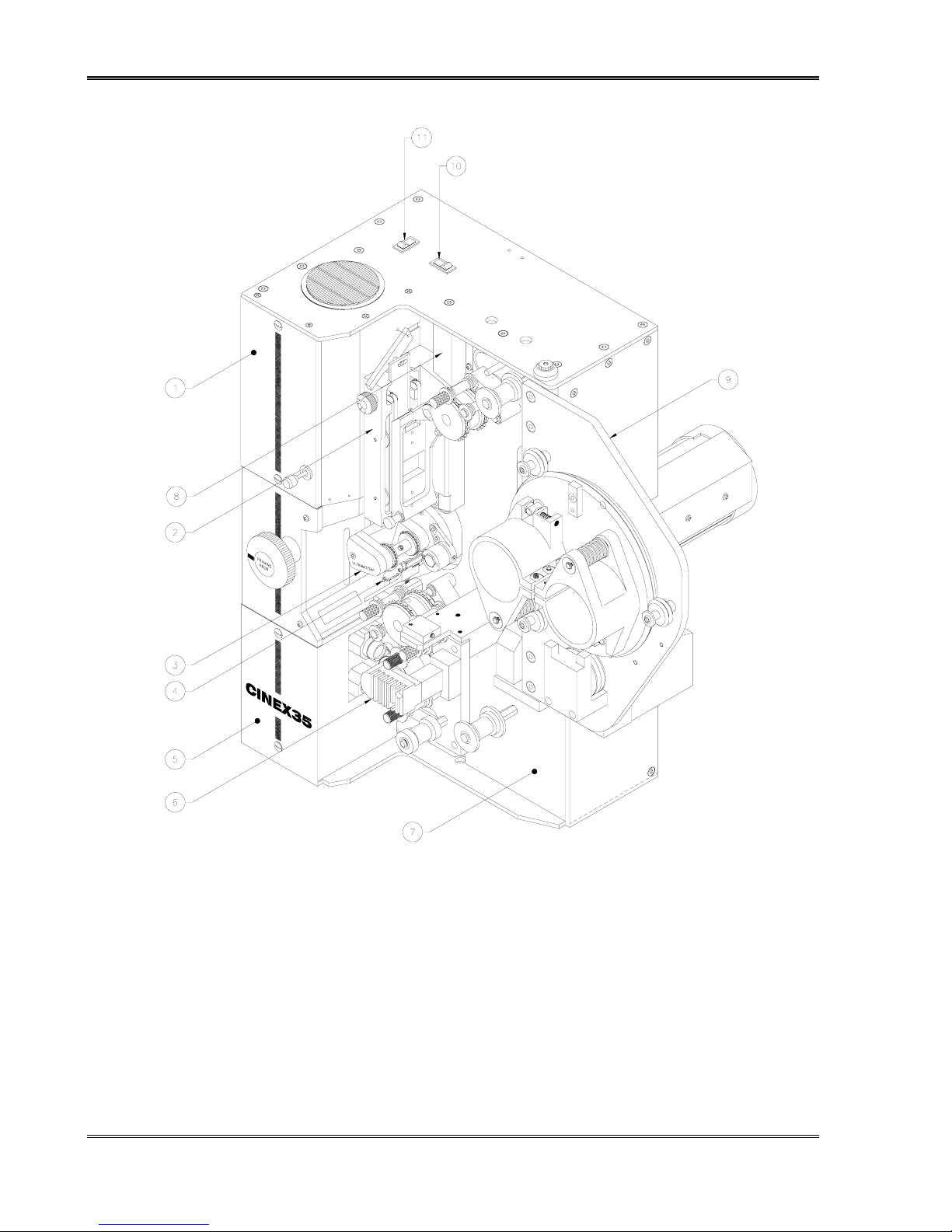
1. Door, Framing Lamp (197576-001
2. Trap and Gate Assembly (197552-001)
3. Ultramittent Assembly (119450-005)
4. Ultramittent Shoe Closure (197578-001)
5. Door, Sound Readers (197549-001)
6. Sound Head Assembly (197510-001)
Figure 2-2: Projector, Front View
CHRISTIE DIGITAL SYSTEMS CineX35 Projector 2-2
May, 2004
7. Main Frame Assembly (197560-001)
8. Shutter Belt Cover (194600-001)
9. Basic Turret Assembly (197100-100)
10. Switch, Flat-Scope (578900-040)
11. Switch, Framing Lamp (578900-042)
2: General Description
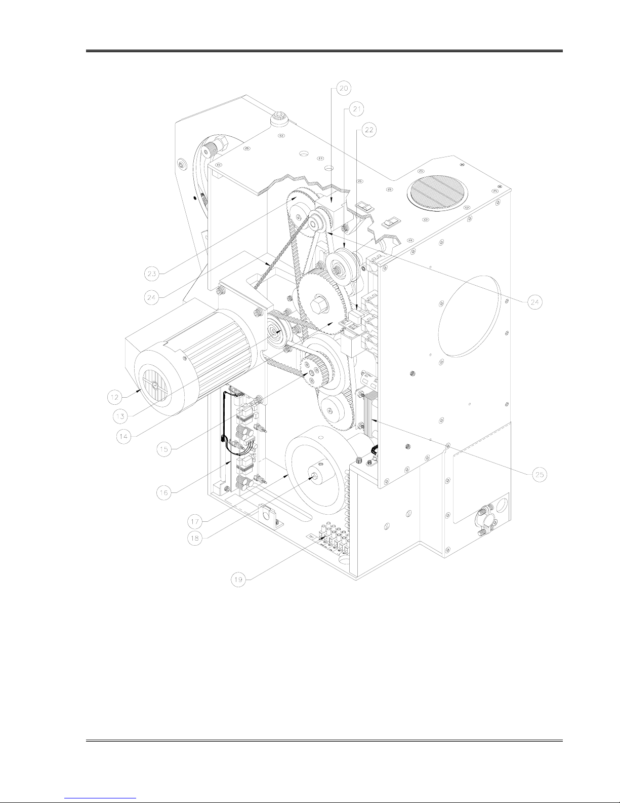
12. Motor Assembly 60-Hz (197553-001)
Motor Assembly 50-Hz (197553-002)
13. Idler Roller Assembly (194879-001)
14. Shutter Drive Assembly (197137-XXX)
15. Pulley 30 Grooves, Ultramittent (197516-001)
16. Power Supply Assembly, Sound-Head (197090-
001)
17. Flywheel, Sound Drum (119166-001)
18. Shaft, Sound Drum (196315-001)
CHRISTIE DIGITAL SYSTEMS CineX35 Projector 2-3
May, 2004
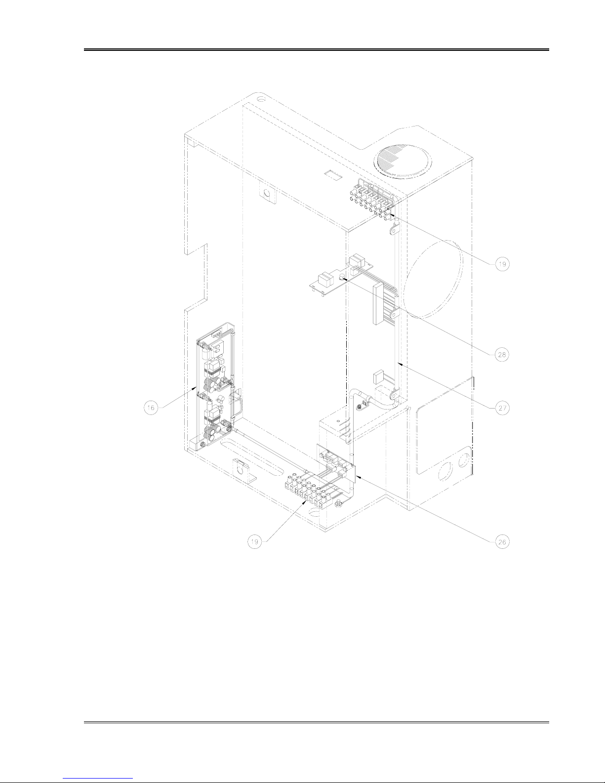
19. Terminal Block Euro 10MM (586210-
008)
20. Jackshaft Assembly (197551-001)
21. Outer Belt Tensioner (197583-001)
22. Light Baffle & Changeover (197550-001)
23. Pulley, 48 Grooves (2 PLS) (197517-001)
24. Belt 5MR-1050 (2 PLS) (598931-177)
25. Turret Auto Control, Option (197580-001)
Figure 2-3: Projector, Rear View

2: General Description
CHRISTIE DIGITAL SYSTEMS CineX35 Projector 2-4
May, 2004
2: General Description
26. Dual LED Regulator (197084-001)
27. Harness (197080-001)
CHRISTIE DIGITAL SYSTEMS CineX35 Projector 2-5
May, 2004
28. Fuse 1A, 250V, SLO-BLO (546101-012)
Figure 2-4: Projector


3
3. PROJECTOR INSTALLATION AND
ASSEMBLY
3.1. UNPACKING THE PROJECTOR
Before opening box (es), carefully inspect outside of carton(s). If carton
has been damaged, notify shipper immediately; do not open carton
unless instructed to do so.
The CHRISTIE projector may be shipped in more than one container. Each projector
normally comes complete with the following items:
• dual aperture plate (shipped in place)
• framing lamp (installed)
•
sound-head flywheel (not installed)
•
sound-head assembly (factory-aligned)
•
dual-lens turret
• drive motor assembly
• instruction manual.
The console and projector are shipped in a single carton, with special pockets containing
smaller items. Sound-head flywheel are shipped separately.
To unpack:
1. Open carton(s).
2. Remove all protective material from framing lamp, sound-head assembly, and lens
holder.
3. Remove protective material around side panel.
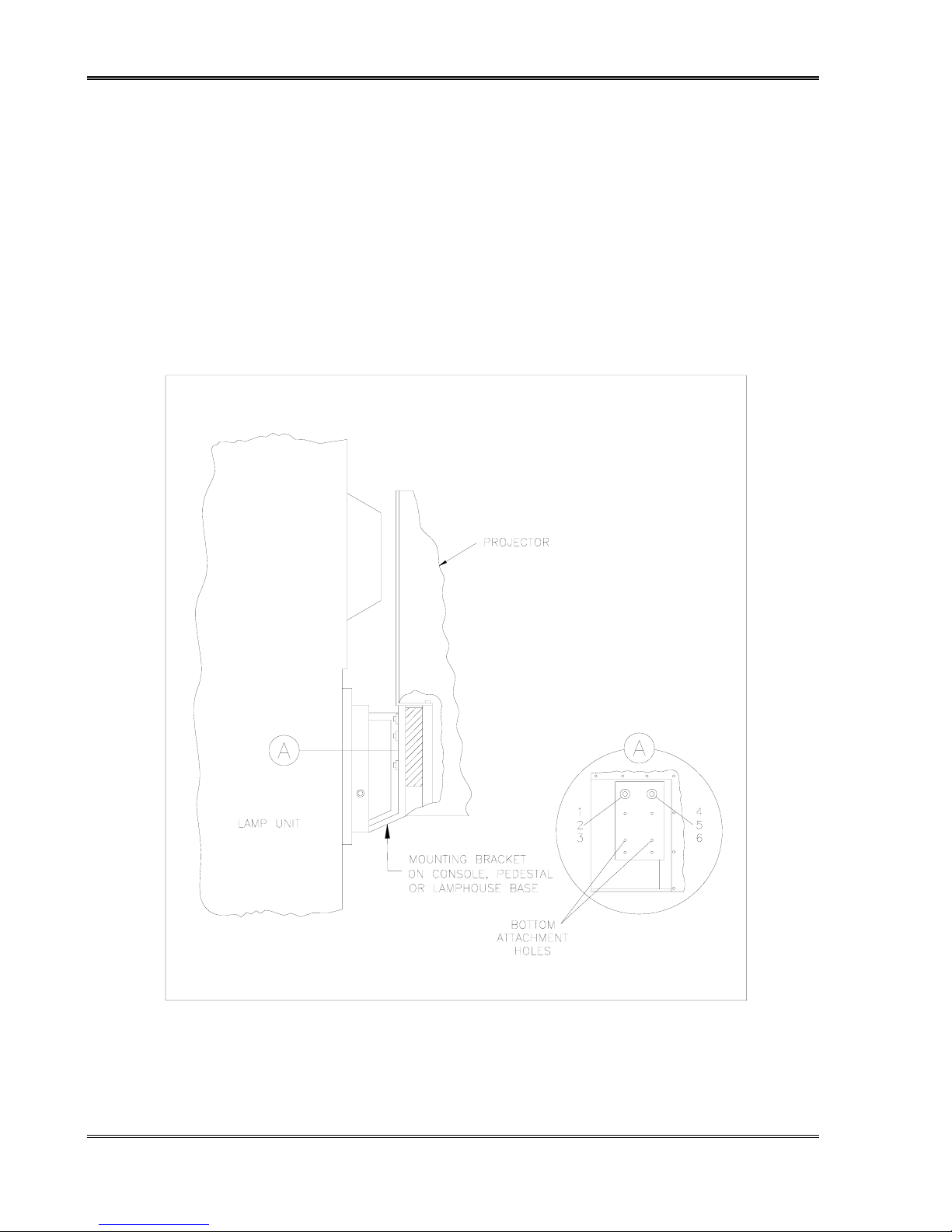
3.2. INSTALLATION
To install the projector, refer to Figure 3-1. The required materials and tools for installing
and assembling the projector are outlined in the Table in Figure 3-2.
1. Loosen but do not remove nut on projector mounting stud (item 4 in Figure 3-1). Verify
that lock washer (item 5 in Figure 3-1) and flat washer (item 6 in Figure 3-1) are
correctly positioned on mounting stud. Flat washer should be next to lock washer,
followed by nut.
CHRISTIE DIGITAL SYSTEMS CineX35 Projector 3-1
May, 2004
3: Projector Installation and Assembly
2. Insert lock washer (item 2 in Figure 3-1) and flat washer (item 3 in Figure 3-1) onto hex
bolt (item 1 in Figure 3-1). Insert hex head bolt, with lock washer and flat washer, into
upper left opening of projector mount. Rotate hex head bolt four full turns.
3. Lift and mount projector to console or pedestal. Thread two remaining hex head bolts
with lock washer and flat washer. Insert into two bottom mounting holes on projector.
4. Level projector on lamp-house or pedestal.
5. Tighten nut on mounting stud using 9/16" wrench.
6. Tighten three hex head bolts using same wrench.
Figure 3-1: Installing the Projector
CHRISTIE DIGITAL SYSTEMS CineX35 Projector 3-2
May, 2004

3: Projector Installation and Assembly
Category Item Use
Tools
Miscellaneous Allen wrenches General Maintenance
Small standard screwdriver
Phillips screwdrivers
Equipment
Oscilloscope Sound-head Alignment
Voltmeter
Real-time Analyzer
Materials
SK1994-3 alignment tool Lateral Guide Alignment
P35-BT (SMPTE) Buzz Track Test Loop
P35-FL Flutter Loop
Cat 69 Loop Dolby Tone, Pink Noise
Cat 566 Loop Illumination Uniformity
Cat 97 Loop Left/Right Alignment
RP-40 Loop Optical Alignment
Figure 3-2: Tools and Materials Required for Assembly and Maintenance
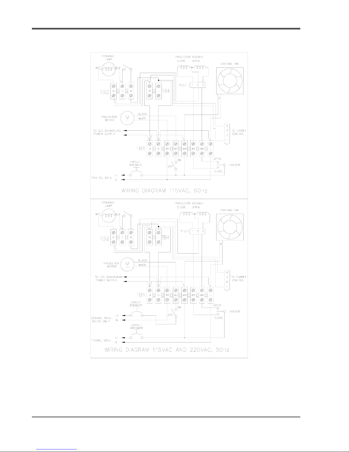
3.3. ELECTRICAL CONNECTIONS
Before wiring the projector, refer to Figure 3-3 for the wiring interface diagram. Use
stranded wire. Strip and tin the wire prior to connection. Use crimp connectors on all sound
connections. For projectors equipped with an automatic turret, refer to Section 6.6.3.
3.3.1. SOLAR C ELL W IRING
Solar cell wiring requires a shielded, four-conductor audio cable. (red – left (+), black – left
(-), green – right (+), white – right (-)). The best signal-to-noise ratio is achieved by
maintaining the same ground potential between the sound-head and the cinema processor.
Refer to the directions in the sound system instruction manual for proper connection of the
sound system.
CHRISTIE DIGITAL SYSTEMS CineX35 Projector 3-3
May, 2004
3: Projector Installation and Assembly
Figure 3-3: Projector Wiring Diagram (50- and 60-Hz models)
CHRISTIE DIGITAL SYSTEMS CineX35 Projector 3-4
May, 2004

3: Projector Installation and Assembly
3.3.2. A-C PROJECTOR W IRING
AC wiring to the projector requires stranded, 14-gauge wire. Be sure to follow local and
national electrical codes for A-C wiring. The terminal connection numbers in the table in
Figure 3-4 refer to terminals TB-1 in Figure 3-3.
Terminal TB1 Connection
A Power Supply (AC-hot)
B Power Supply (AC- neutral)
W1 Motor (AC neutral)
W3 Motor switch lead (AC hot, switched externally)
W4 Cooling Fan, Turret Control (AC-hot)
W5 Douser coil CLOSE (AC-hot switched externally)
W6 Douser coil OPEN (AC-hot switched externally)
J Cooling Fan, Turret Control and Douser (AC neutral).
Figure 3-4: Table of A-C Terminal Connections
The voltage and frequency rating of the projector (shown on the
nameplate) must match the power line frequency and voltage being
used.
CHRISTIE DIGITAL SYSTEMS CineX35 Projector 3-5
May, 2004


4
4. OPERATING THE PROJECTOR
4.1. GENERAL
Before operating the projector, verify that all phases of installation and assembly have been
completed.
• Verify that cover for belt side of projector is installed before and
during operation.
• Do not make adjustments on belt side of projector while cover is
WARNING
removed and power is on.
• Do not make adjustments or perform maintenance on projector
while it is in operation.
4.2. PRE-OPERATING PROCEDURES
4.2.1. FLYWHEEL I NSTALLATION
1. Back out flywheel set screw far enough to let flywheel slide onto shaft without scoring
shaft or damaging threads on set screw.
2. Slide flywheel onto shaft until it stops.
3. Position set screw over flat portion of shaft and tighten set screw.
4. Spin flywheel by hand to check for smooth operation.
CHRISTIE recommends that any projector accessories be installed at
this time.
4.2.2. L ENS I NSTALLATION
1. Install lens system in lens holder. If it is necessary to open lens holder wider than
normal:
a) Loosen two lens-locking screws.
b) Turn jack screw clockwise until lens slides into lens holder; turn the screw back.
2. Set focus knob at mid-position.
CHRISTIE DIGITAL SYSTEMS CineX35 Projector 4-1
May, 2004

4: Operating the Projector
3. Secure lens system with two locking screws.
Over-tightening can cause focus mechanism to bind.
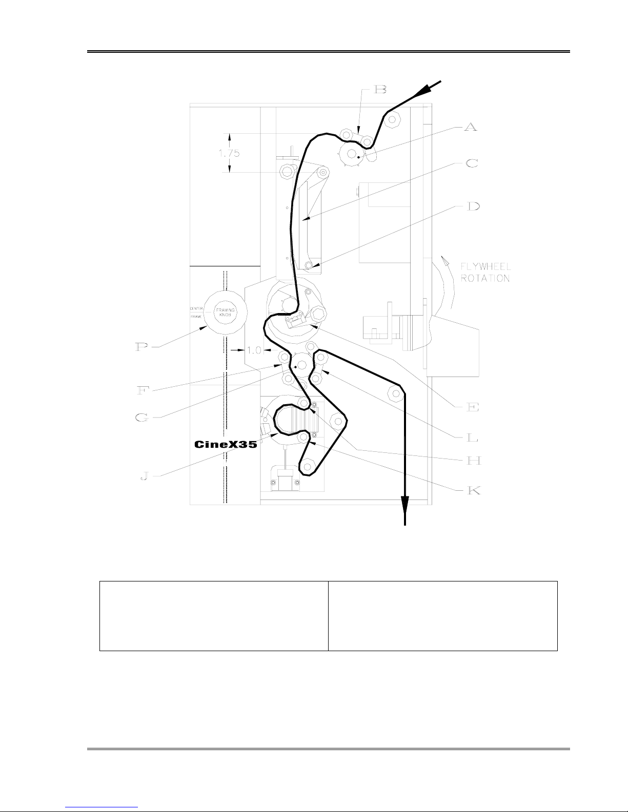
4.3. FILM THREADING AND O PERATING PROCEDURE
Refer to Figure 4-1 for film threading and positioning using flywheel.
1. Set Ultramittent to its rest position. There should be no sprocket movement when motor
flywheel is turned.
2. Center framing knob (P) by aligning mark on knob with line on projector housing marked
CENTER FRAME.
3. Swing out pad rollers (B, F, L) on constant-speed sprockets (A & G).
4. Swing out film shoe on Ultramittent assembly (E).
5. Pull out catch knob (D) and swing out gate assembly (C).
6. Using slightly more film length than is required to reach film transport system, begin to
thread film into projector.
7. Align film on Ultramittent sprocket and close Ultramittent film shoe.
8. To form proper loop between Ultramittent and lower constant-speed sprocket:
a) Pull film loosely over lower constant-speed sprocket, form loop as shown on Figure
4-1.
b) Mate film sprocket holes with sprocket pins.
c) Hold film in position and close pad rollers.
9. Thread film on sound-head assembly as shown in Figure 4-1:
a) Holding two lateral guide rollers (H and K) towards each other, pull film tight and
align film on lower constant-speed sprocket assembly (G).
b) Tighten film on one sprocket hole so lateral guides barely float off sound drum.
c) Close pad rollers (L) of lower constant-speed sprocket.
CHRISTIE DIGITAL SYSTEMS CineX35 Projector 4-2
May, 2004
4: Operating the Projector
A: Upper Constant Speed Sprocket G: Lower Constant Speed Sprocket
B: Pad Rollers, Upper Speed Sprocket H: Lateral Guide Roller (Upper)
C: Gate Assembly J: Sound Drum
D: Catch knob K: Lateral Guide Roller (Lower)
E: Ultramittent Shoe Assembly L: Pad Rollers, Lower Constant Speed Sprocket
F: Pad Rollers, Lower Constant Speed Sprocket P: Framing Knob
CHRISTIE DIGITAL SYSTEMS CineX35 Projector 4-3
May, 2004
Figure 4-1: Threading Diagram
 Loading...