

Christie 103-006101-01, 103-007101-01 Quick Reference Manual
Multimedia Projector
Quick Reference Guide
MODEL
103-006101-01
103-007101-01
✽ Projection lens is optional.
Use this book as a reference guide when setting up the projector. For
detailed information about installation, setup, and operation of the projector,
refer to the owner’s manual on the CD-ROM.
Read the Safety Instructions in the owner’s manual before using the
projector.
EnglishDeutsch FrançaisItaliano Español
Printed in Japan
Part No.610 330 3703 (1AA6P1P5212-- KF6K)

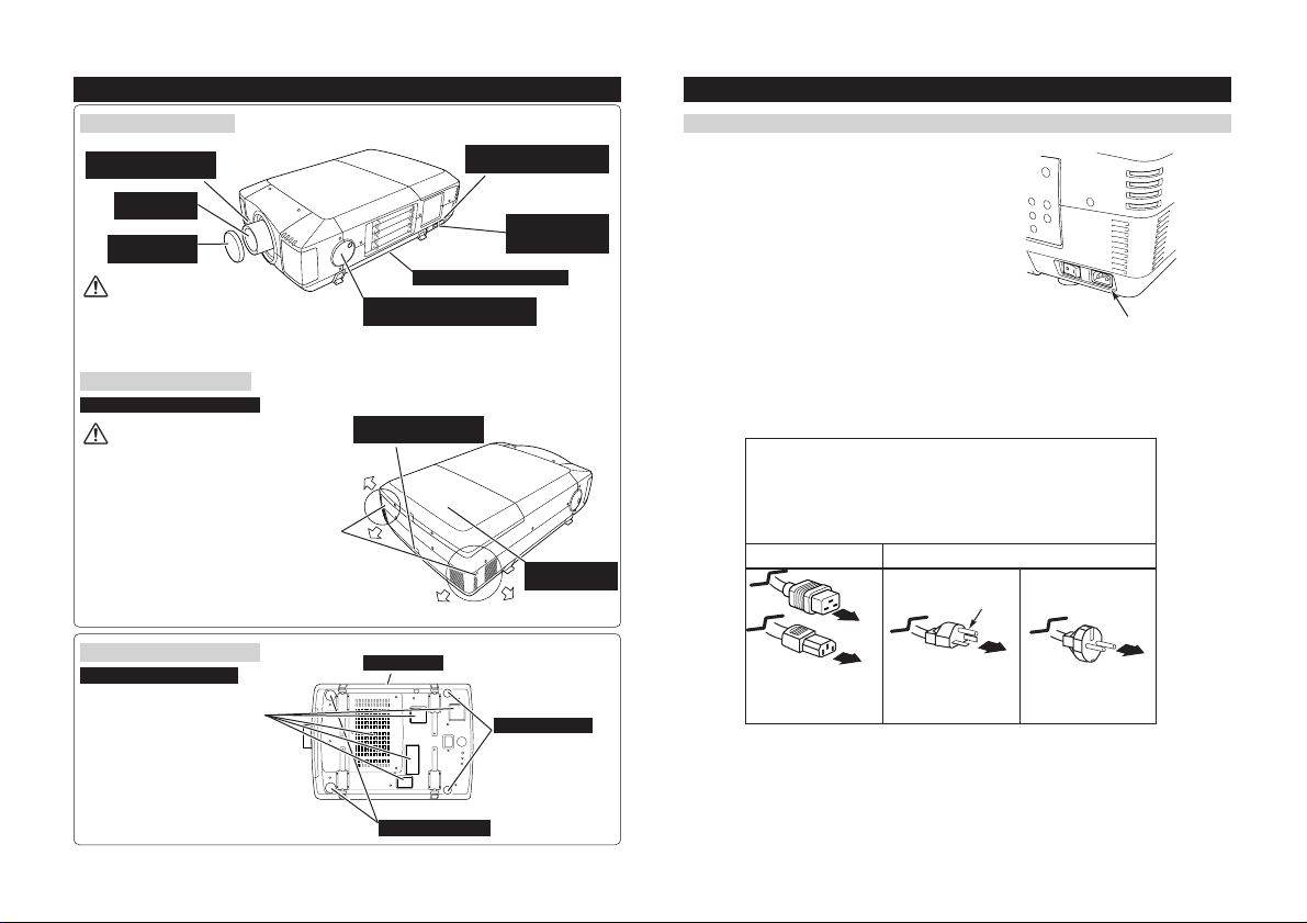
NAME OF EACH PART OF PROJECTOR
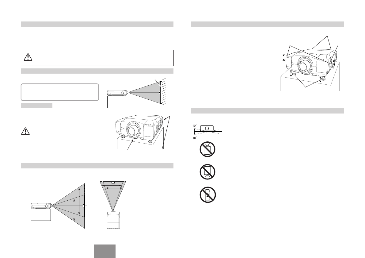
FRONT OF CABINET
INFRARED
REMOTE RECEIVER
PROJECTION LENS
LENS CAP
CAUTION
Do not turn on a projector with lens cap
attached. High temperature from light beam
may damage lens cap and result in fire hazard.
BACK OF CABINET
EXHAUST VENT
-2-
HOT AIR EXHAUSTED !
Air blown from exhaust vent is hot.
When using or installing a projector,
following precautions should be taken.
● Do not put a flammable object near this
vent.
● Keep rear grills at least 3.3’ (1m) away from
any object, especially heat-sensitive object.
● Do not touch this area, especially screws
and metallic parts. This area will become
hot while a projector is used.
This projector detects internal
temperature and automatically controls
operating power of Cooling Fans.
BOTTOM OF CABINET
AIR INTAKE VENTS
This projector is equipped with
cooling fans for protection from
overheating. Pay attention to
following to ensure proper
ventilation and avoid a possible risk
of fire and malfunction.
● Do not cover vent slots.
● Keep bottom clear of any objects.
Obstructions may block cooling air.
CARRYING HANDLE
LEVEL AND TILT ADJUST HANDLE
INFRARED
REMOTE RECEIVER
AIR FILTER
ADJUSTABLE FEET
POWER CORD
CONNECTOR
MAIN ON / OFF
SWITCH
LAMP COVER
ADJUSTABLE FEET
SETTING-UP PROJECTOR
CONNECTING AC POWER CORD
This projector uses nominal input voltages of 120 V or
200-240 V AC. This projector automatically selects
correct input voltage. It is designed to work with singlephase power systems having a grounded neutral
conductor. To reduce risk of electrical shock, do not plug
into any other type of power system.
Consult your authorized dealer or service station if you
are not sure of the of the power supply being in use.
Connect the projector with peripheral equipment before
turning the projector on.
CAUTION
AC Power Cord must meet requirement of country where you use a projector.
Confirm AC plug type with chart below and proper AC power cord must be used.
If supplied AC Power Cord does not match AC outlet, contact your sales dealer.
To AC Outlet.
(120 V AC)
AC Outlet side
Ground
Projector side
To POWER CORD
CONNECTOR on a
projector.
For U.S.A. and Canada
Connect the AC Power Cord
(supplied) to the projector.
AC outlet must be near this
equipment and must be easily
accessible.
For Continental Europe
To AC Outlet.
(200 - 240 V AC)

Before setting up a projector, install Projection Lens on the Projector.
1. Before installation, check where the projector is used and prepare suitable lens. For specifications of the
Projection Lens, refer to the manual separately attached or contact sales dealer where you purchased the
projector.
2. For installation, refer to the installation manual supplied to the Projector.
When moving or setting up the projector, be sure to replace the Lens Cap to protect the surface.
And be careful not to hold or subject the lens to strong forces. It may damage lens, cabinet, or
mechanical parts.
POSITIONING THE PROJECTOR
LENS INSTALLATION
This projector is designed to project on a flat projection
surface.
ROOM LIGHT
Brightness in the room has a great influence on
picture quality. It is recommended to limit ambient
lighting in order to provide best image.
SCREEN
VENTILATION
This projector is equipped with cooling fans to protect it from
overheating. Pay attention to following to ensure proper
ventilation and avoid a possible risk of fire and malfunction.
-3-
● Do not cover vents with papers or other materials.
Keep rear grill at least 3.3 feet (1 m) away from any
●
object.
● Make sure that there are no objects under the
projector. Any object under the projector may
prevent the projector from taking cooling air through
bottom vent.
AIR INTAKE VENT
(BOTTOM SIDE)
LENS SHIFT ADJUSTMENT
Projection lens can be moved up, down, left and right with motor-driven lens shift function. This function
makes it easy to provide projected image where you want.
Use the LENS SHIFT button
and the POINT UP/DOWN
button to move image up or
down.
Use the LENS SHIFT button
and POINT LEFT/RIGHT
button to move image left or
right.
EXHAUST VENT
(REAR SIDE)
PICTURE LEVEL AND TILT ADJUSTMENT
Picture tilt and projection angle can be adjusted with
handles on both sides of a projector. Projection angle
can be adjusted to 5.7 degrees upper way.
Press the knob on the handle. The handle pops
1
out.
Turn handles (right and left) until the picture is
2
projected on proper position. Adjust height of rear
adjustable feet by rotating them until the projector
is properly stabled on the table.
Press the knob and retract the handle.
3
LEVEL AND TILT
ADJUST HANDLE
ADJUSTABLE
FEET
Height of front feet can be
adjusted by turning handles.
REAR ADJUSTABLE
FEET
INSTALLING PROJECTOR IN PROPER POSITION
Install the projector properly. Improper installation may reduce the lamp lifetime and cause a fire hazard.
Do not tilt the projector more than 10 degrees above and below.
Do not point the projector up to project an image.
NO UPWARD
Do not point the projector down to project an image.
NO DOWNWARD
Do not put the projector on either side to project an image.
KNOB
MOVED UP OR DOWN MOVED LEFT OR RIGHT
English
NO SIDEWAYS
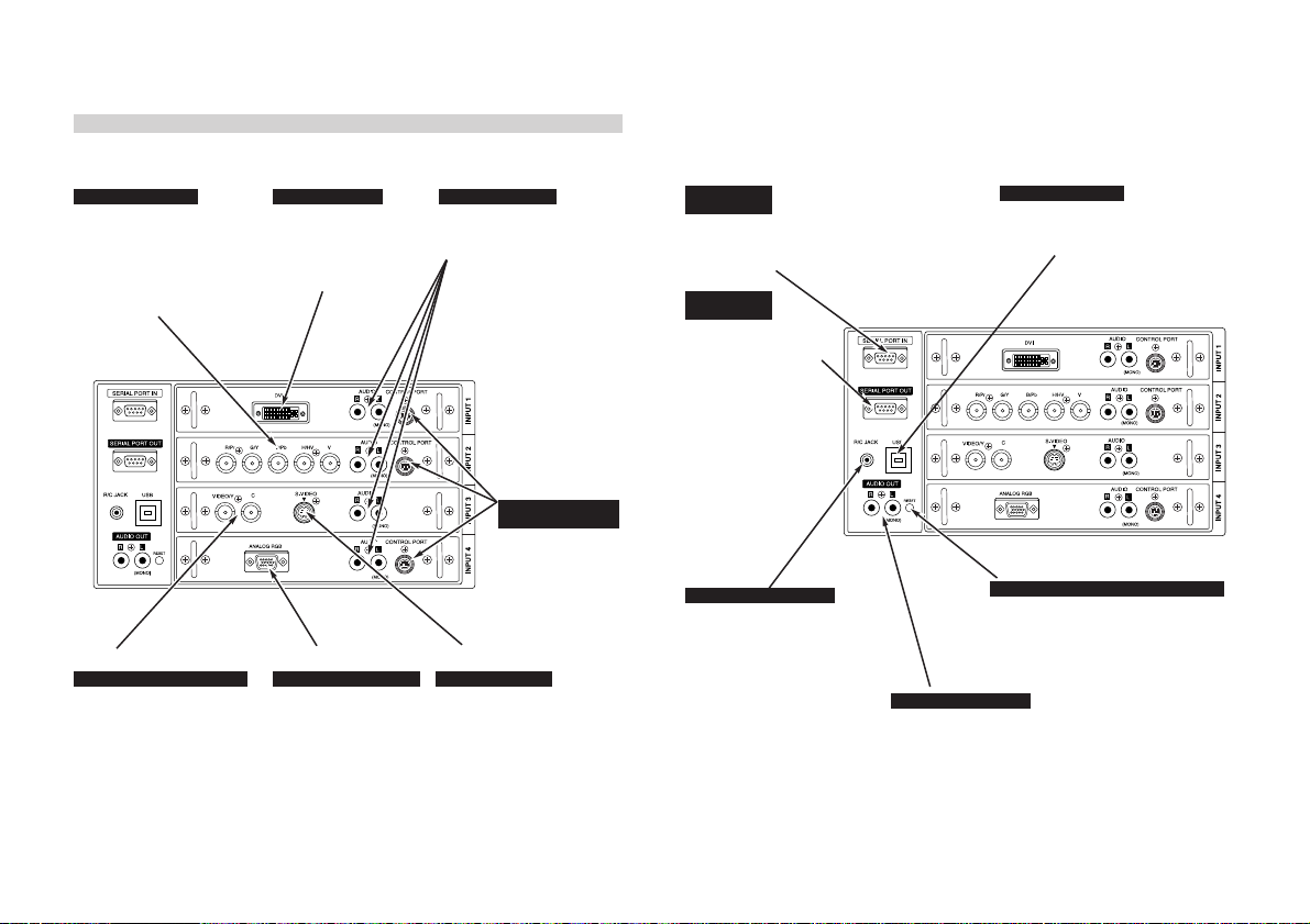
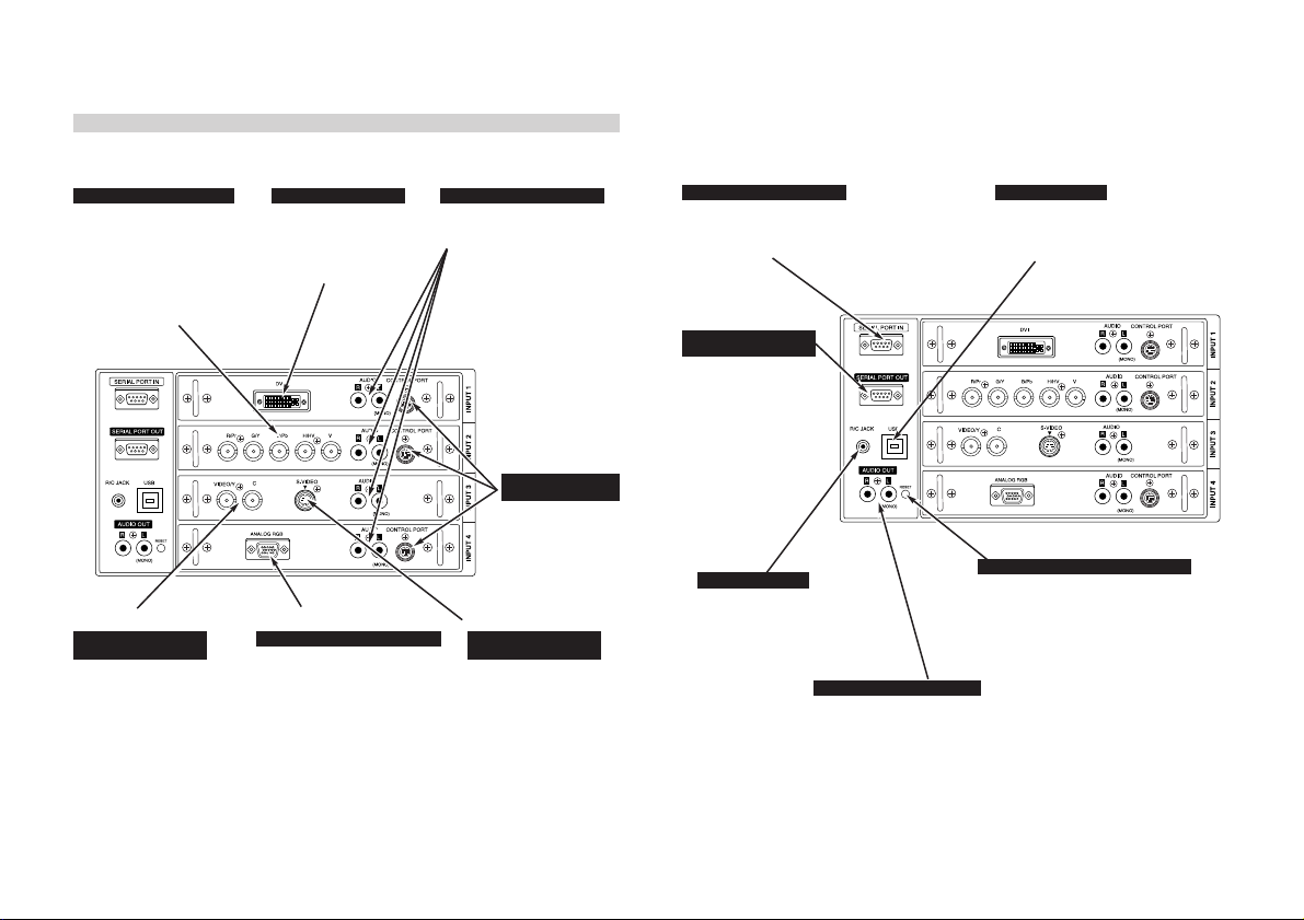
INPUT/OUTPUT TERMINALS AND JACKS
INPUT 2 INPUT 1 INPUT 1, 2, 3, 4
5 BNC INPUT JACKS
Connect component video output
(Cr, Y, Cb or Pr, Y, Pb) from video
equipment to R/Pr, G/Y and B/Pb
jacks or connect computer
output [5 BNC Type (Red, Green,
Blue, Horiz. Sync and Vert.
Sync.)] from computer to R/Pr,
G/Y, B/Pb, H/HV and V jacks.
DVI INPUT TERMINAL
Connect computer output
(Digital/Analog DVI-I type)
to this terminal.
HD (HDCP Compatible)
signal can also be
connected.
-4-
INPUT 3INPUT 4INPUT 3
Connect composite video output
from video equipment to VIDEO/Y
jack or connect Separate Y/C video
outputs to VIDEO/Y and C jacks.
HDB 15-PIN INPUT TERMINALAV INPUT (VIDEO/Y, C) JACKS
Connect computer output
(Analog HDB 15-pin type)
to this terminal.
AUDIO INPUT JACKS
Connect audio output
from computer or video
equipment to these
jacks.
INPUT 1, 2, 4
CONTROL PORT
CONNECTORS
The port is not
functioning in this
model.
S-VIDEO INPUT JACK
Connect S-VIDEO
output from video
equipment to this jack.
SERIAL PORT
IN TERMINAL
If you control a projector by
computer, you must connect a
cable (not provided) from your
computer to this terminal.
SERIAL PORT
OUT TERMINAL
This terminal outputs
signal from SERIAL PORT
IN. More than two
projectors can be
controlled with one
computer by connecting
SERIAL PORT IN. of
another projector to this
terminal.
R/C JACK
When using Wired / Wireless
Remote Control Unit as Wired
Remote Control, Connect
Wired Remote Control Unit to
this jack with Remote Control
Cable (supplied).
This port is used to service the
projector.
Connect USB port of computer to
this port.
This projector uses a micro processor to
control unit. Occasionally, micro processor
may malfunction and need to be reset. This
can be done by pressing the RESET button
with a pen, which will shut down and restart
unit. Do not use RESET function excessively.
AUDIO OUTPUT JACKS
Connect an external audio
amplifier to these jacks.
USB PORT (Series B)
RESET BUTTON
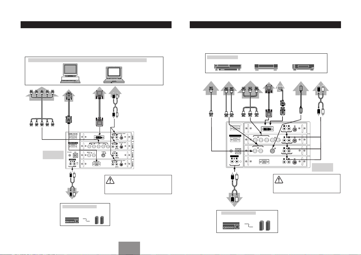
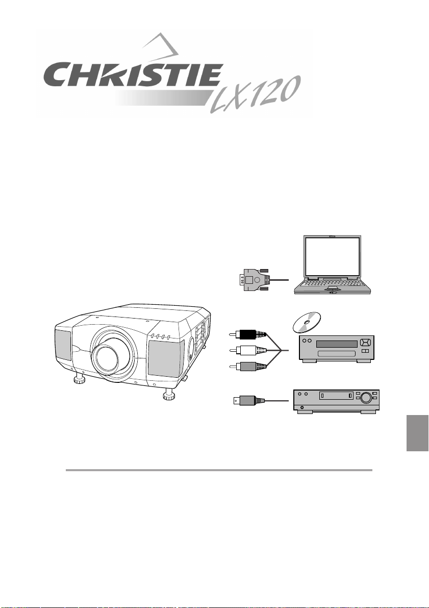
CONNECTING TO COMPUTER
Cables used for connection (✽ = Cables are not supplied with this projector.)
• VGA Cable (HDB 15 pin)
✽
• DVI Cable
• BNC Cable (BNC x 5) ✽
• Audio Cable (RCA x 2) ✽
CONNECTING TO VIDEO EQUIPMENT
Cables used for connection (✽ = Cables are not supplied with this projector.)
• Video Cable (BNC x 1, BNC x 2 or BNC x 3)
• HDB 15 pin-Scart 21 pin Cable ✽ • DVI-VGA Adapter ✽
• S-VIDEO Cable ✽ • Audio Cable (RCA x 2) ✽
✽ • DVI Cable ✽
-5-
IBM-compatible computers or Macintosh computers (VGA / SVGA / XGA / SXGA / WXGA / UXGA)
Desktop type Laptop type
Monitor Output
BNC Cable ✽
Terminals of
a Projector
Monitor Output
VGA Cable
DVI Cable ✽
AUDIO OUT
Audio Cable
(stereo) ✽
Monitor Output
Audio Output
Audio Cable
(stereo) ✽
NOTE :
When connecting cable, power cords of both a
projector and external equipment should be
disconnected from AC outlet. Turn a projector
and peripheral equipment on before computer is
switched on.
Audio Input
External Audio Equipment
Audio Amplifier
Audio Speaker
(stereo)
Video Source (example)
Video Cassette Recorder
Composite
Video Output
Video
Cable ✽
Cable ✽
VIDEO
Separate Y/C
Video Output
YC
Video
Y-C
SERIAL PORT IN
SERIAL PORT OUT
R/C JACK
AUDIO OUT
R
(MONO)
Audio Input
External Audio Equipment
Audio Amplifier
Component
Video Output
Pr/Cr
Video
Cable ✽
USB
L
RESET
AUDIO OUT
Audio Cable
(Stereo) ✽
Video Disc Player
Digital Output
compatible)
Y
Pb/Cb
Cable
Pr/Cr-Y-Pb/Cb
R/Pr G/Y B/Pb H/HV V
C
VIDEO/Y
ANALOG RGB
Audio Speaker
(stereo)
(HDCP
DVI
Component video output
equipment.
(such as DVD player or
high-definition TV source.)
RGB Scart
S-VIDEO
21-pin
Output
HDB 15 pinSCART 21
✽
pin Cable ✽
DVI-VGA
Adapter ✽
DVI
AUDIO
DVI
S-VIDEO
CONTROL PORT
L
R
(MONO)
AUDIO
CONTROL PORT
R
L
(MONO)
AUDIO
R
L
(MONO)
AUDIO
CONTROL PORT
R
L
(MONO)
NOTE :
When connecting cable, power cords of both a
projector and external equipment should be
disconnected from AC outlet. Turn a projector
and peripheral equipment on before computer is
switched on.
Output
S-VIDEO
Cable
S-VIDEO
Audio Output
RL
✽
INPUT 1
INPUT 2INPUT 3INPUT 4
Terminals of
a Projector
Audio Cable
(Stereo) ✽
AV AUDIO IN
English
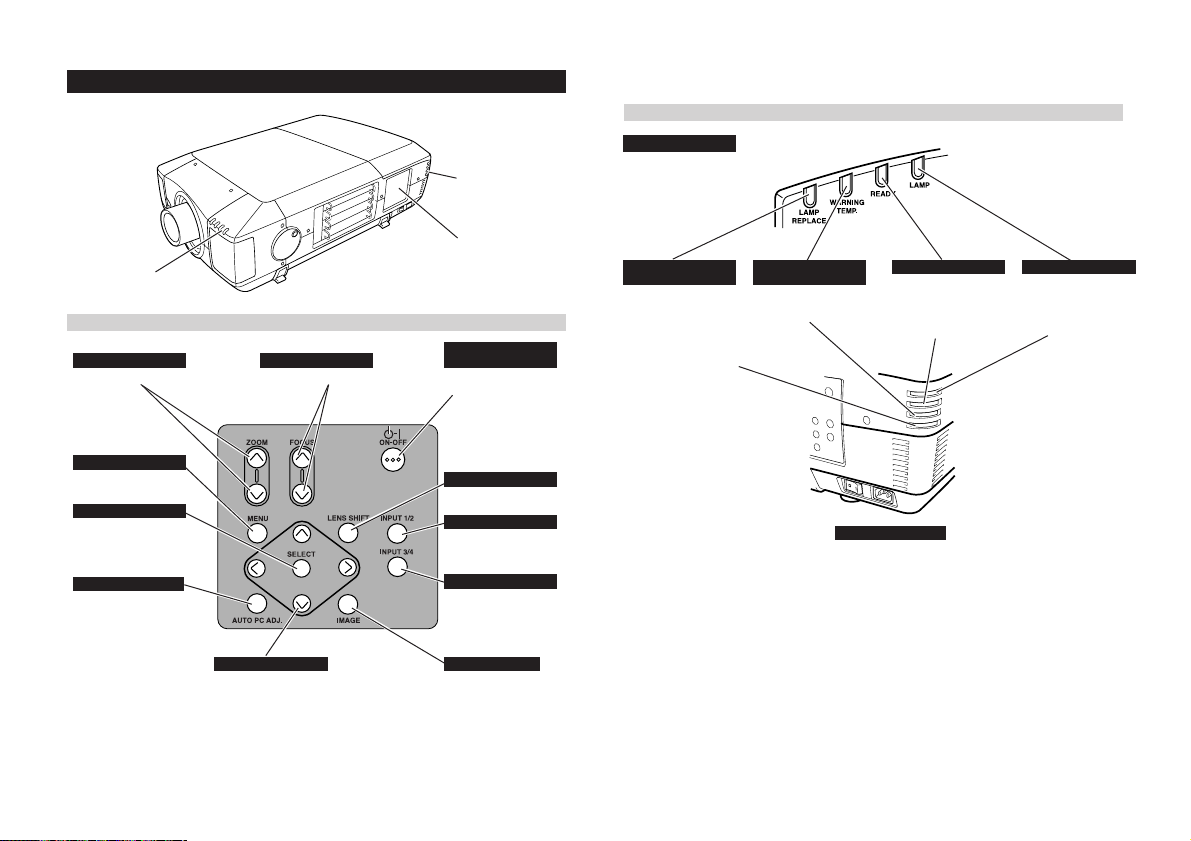
SIDE CONTROLS AND INDICATORS
WARNING
TEMP.
READY
LAMP
REPLACE
LAMP
REAR
INDICATORS
INDICATORS
FRONT INDICATORS
-6-
FRONT
INDICATORS
ZOOM BUTTONS
Used to adjust zoom.
MENU BUTTON
Used to open or close
MENU operation.
SELECT BUTTON
Used to execute item
selected. It is also used
to expand image in
DIGITAL ZOOM mode.
AUTO PC ADJ. BUTTON
Use to operate AUTO
PC Adjustment function.
SIDE CONTROLS
FOCUS BUTTONS
Used to adjust focus.
POINT BUTTONS
Used to select an item or
adjust value in MENU. It
is also used to pan image
in DIGITAL ZOOM mode.
SIDE CONTROLS
POWER ON–OFF
BUTTON
Used to turn a projector
on or off.
LENS SHIFT BUTTON
Used to select LENS
SHIFT function.
INPUT 1/2 BUTTON
Used to select input
source either INPUT 1 or
INPUT 2.
INPUT 3/4 BUTTON
Used to select input
source either INPUT 3 or
INPUT 4.
IMAGE BUTTON
Used to select
image level.
LAMP REPLACE
INDICATOR
This LAMP REPLACE
indicator lights yellow
when any of Projection
Lamps is nearing its end,
and flashes when any of
them becomes out.
Check which lamp
needs to be replaced on
Lamp Status Display.
WARNING TEMP.
INDICATOR
This indicator flashes red
when internal projector
temperature is too high.
READY INDICATOR LAMP INDICATOR
This indicator lights
green when a projector
is ready to be turned on.
And it flashes green in
Power Management
mode.
REAR INDICATORS
This indicator is dim
when a projector is
turned on. And bright
when a projector is in
stand-by mode.
LIGHT BUTTON
Lights the buttons on
the remote control for
about 10 seconds.
MENU BUTTON
Used to select MENU
operation.
POINT (UP / DOWN / LEFT /
RIGHT) BUTTONS
Used to select an item or
adjust value in ON-SCREEN
MENU. They are also used to
pan image in DIGITAL ZOOM
+/– mode.
LENS SHIFT BUTTON
-7-
Used to select LENS
SHIFT function.
ZOOM BUTTONS
Used to adjust zoom.
FREEZE BUTTON
Used to freeze picture.
P-TIMER BUTTON
Used to operate P-TIMER
function.
OPERATION OF REMOTE CONTROL
AUTO PC ADJ. BUTTON
Used to operate AUTO
PC Adjustment function.
WIRED REMOTE JACK
When using as Wired Remote
Control, connect Remote
Control Cable (supplied) to this
jack.
Battery installation is required
when using as Wired Remote
Control.
POWER ON-OFF
BUTTON
Used to turn projector
on or off.
NO SHOW BUTTON
Used to turn picture into
black image.
SELECT BUTTON
Used to execute item
selected. It is also used
to expand / compress
image in DIGITAL
ZOOM mode.
IMAGE ADJ. BUTTON
Used to adjust image
level.
FOCUS BUTTONS
Used to adjust focus.
INPUT 1, 2, 3, 4
BUTTONS
Used to select input
source.
D.ZOOM BUTTON
Used to select DIGITAL
ZOOM +/– mode and
resize image.
KEYSTONE BUTTON
Used to correct
keystone distortion.
IMAGE SEL. BUTTON
Used to select image
level.
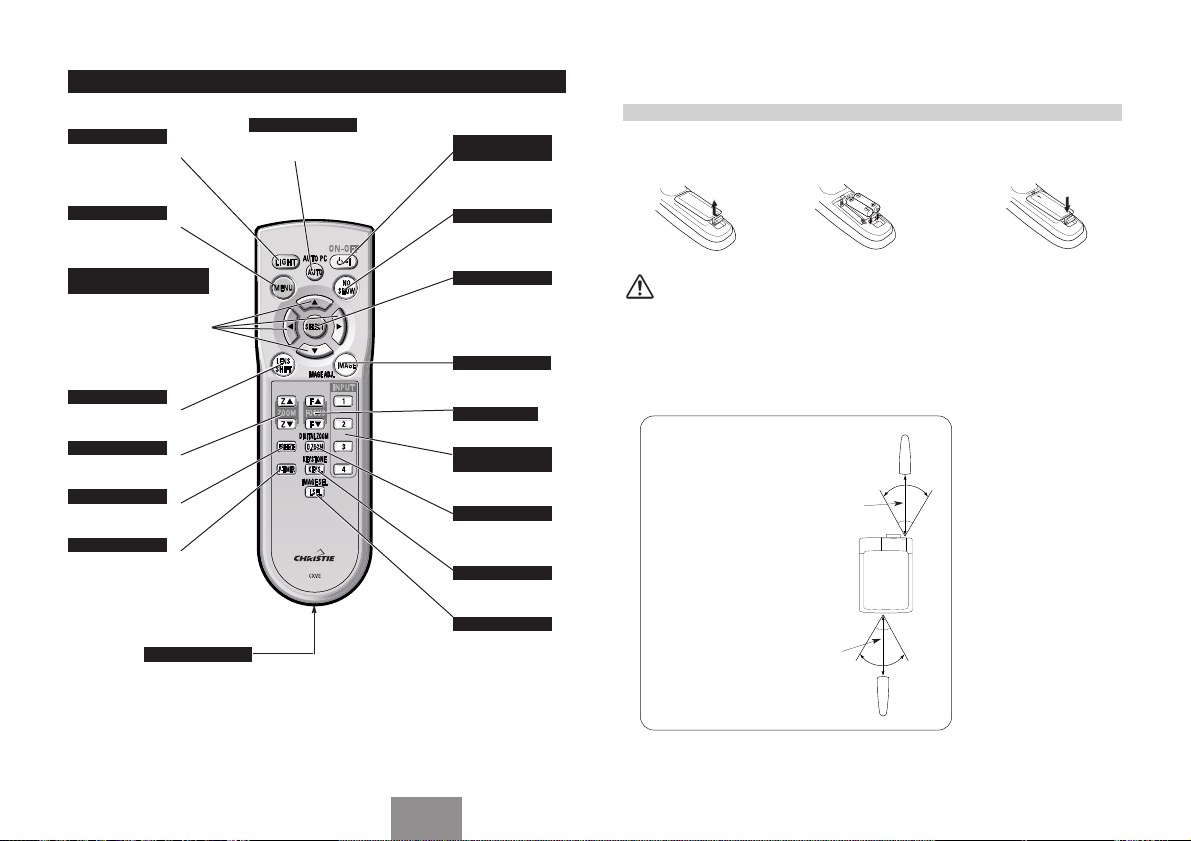
REMOTE CONTROL BATTERIES INSTALLATION
Remove battery
12 3
compartment lid.
Pull up lid and
remove it.
To insure safe operation, please observe following precautions :
● Use (2) AA or R06 type alkaline batteries.
● Replace two batteries at same time.
● Do not use a new battery with an used battery.
● Avoid contact with water or liquid.
● Do not expose Remote Control Unit to moisture, or heat.
● Do not drop Remote Control Unit.
● If a battery has leaked on Remote Control Unit, carefully wipe case clean and install new batteries.
● Danger of explosion if battery is incorrectly replaced.
● Dispose of used batteries according to batteries manufacturers instructions and local rules.
Operating Range
Point Remote Control Unit
toward projector (Infrared
Remote Receiver) whenever
pressing any button. Maximum
operating range for Remote
Control Unit is about 16.4’ (5m)
and 60° in front and rear of a
projector.
Slide batteries into
compartment.
16.4’
(5 m)
16.4’
(5 m)
60°
Two AA size batteries
For correct polarity (+
and –), be sure
battery terminals are
in contact with pins in
compartment.
60°
Replace the
compartment lid.
English
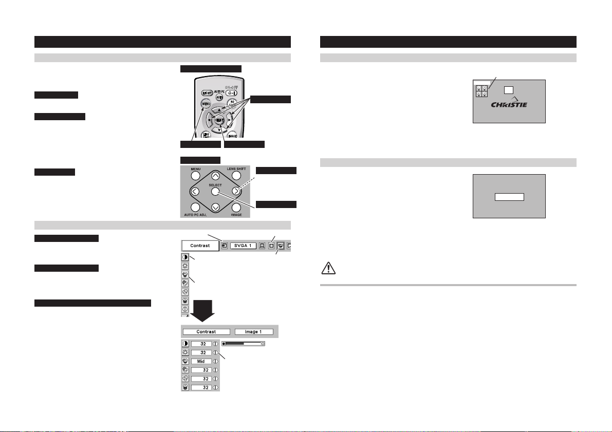
OPERATING ON-SCREEN MENU
HOW TO OPERATE ON-SCREEN MENU
You can control and adjust this projector through ONSCREEN MENU.
1 DISPLAY MENU
Press the MENU button to display ON-SCREEN MENU.
2 MOVING POINTER
Move pointer (✽ see below) or adjust the value of the item
by pressing the POINT button(s) on the Side Control or on
the Remote Control Unit.
✽ The pointer is an icon on the ON-SCREEN MENU to
select an item. See figures on section "FLOW OF ONSCREEN MENU OPERATION" below.
3 SELECT ITEM
Select an item or set the selected function by pressing the
SELECT button.
-8-
FLOW OF ON-SCREEN MENU OPERATION
Display ON-SCREEN MENU
Press the MENU button to display the ON-SCREEN
1
MENU (MENU BAR). A red frame is the POINTER.
Select Menu to be adjusted
Move the POINTER (red frame) to MENU ICON that
2
you want to select by pressing the the POINT LEFT /
RIGHT buttons.
Control or adjust item through ON-SCREEN MENU
Press the POINT DOWN button and move the
3
POINTER (red frame or red arrow) to the ITEM you
want to adjust, and then press the SELECT button to
show the ITEM DATA.
Adjust the ITEM DATA by pressing the POINT LEFT /
4
RIGHT buttons.
For details, refer to the Owner's Manual.
REMOTE CONTROL UNIT
MENU BUTTON
SIDE CONTROL
MENU BAR
SELECT BUTTON
Used to select the item.
POINTER (red frame)
Press the POINT DOWN
button to move the POINTER.
ITEM
SELECT
BUTTON
ITEM DATA
Press the POINT
LEFT/RIGHT buttons to
adjust the value or set the
function.
POINT BUTTONS
Used to move the
Pointer UP/ DOWN/
RIGHT/ LEFT.
POINT BUTTONS
Used to move
Pointer UP/ DOWN/
RIGHT/ LEFT.
SELECT BUTTON
Used to select item.
MENU ICON
POINTER
(red frame)
TURNING ON / OFF PROJECTOR
Press the POWER ON-OFF button on the Side Control or on
the Remote Control Unit to turn on. LAMP indicator dims, and
Cooling Fans start to operate. Preparation Display appears on
the screen and count-down starts. Signal from source appears
after 20 seconds.
Current Input position and Lamp status are also displayed on
the screen for 5 seconds.
Press the POWER ON-OFF button on the Side Control or
1
on the Remote Control Unit, and a message "Power off?"
appears on the screen.
Press the POWER ON-OFF button again to turn off the
2
projector. LAMP indicator lights bright and READY
indicator turns off. After approximate 90 seconds,
READY indicator will light green again and the projector
may be turned on by pressing the POWER ON-OFF
button.
Cooling fans will operate for approximate 2 minutes after
3
the projector is turned off. To power down completely,
turn the MAIN ON/OFF SWITCH to OFF and disconnect
the AC Power Cord.
TO MAINTAIN LIFE OF LAMP, ONCE YOU TURN
THE PROJECTOR ON, WAIT AT LEAST 5 MINUTES
BEFORE TURNING IT OFF.
When Power Management function is ON, the projector detects signal interruption and Projection Lamp is
turned off automatically.
When WARNING TEMP. indicator flashes red, the projector is automatically turned off. Wait at least 5 minutes
before turning on the projector again.
When both WARNING TEMP. and READY indicators to flash, follow procedures below:
1. Turn MAIN ON/OFF SWITCH to OFF.
2. Turn the projector on again.
When WARNING TEMP. indicator continues to flash, follow procedures below:
1. Turn the MAIN ON/OFF SWITCH to OFF and disconnect the AC Power Cord from the AC outlet.
2. Check Air Filters for dust accumulation.
3. Clean Air Filters.
4. Turn the projector on again.
If WARNING TEMP. indicator should still continue to flash, contact the sales dealer where you purchased this
projector or the service center.
TURNING ON PROJECTOR
LAMP STATUS
INPUT 1
Preparation Display disappears
after 20 seconds.
TURNING OFF PROJECTOR
Message disappears after 4 seconds.
20
Power off?
Projecteur multimédia
Guide de référence rapide
MODÈLE
Utilisez ce livret comme guide de référence lorsque vous installez le
projecteur. Pour plus de détails concernant l'installation, la configuration et
l'utilisation du projecteur, reportez-vous au mode d'emploi inclus dans le
CD-ROM. Lisez les instructions de sécurité dans le mode d'emploi avant
d'utiliser le projecteur.
103-006101-01
103-007101-01
✽ La lentille de projection est disponible en option.
Français
NOM DES COMPOSANTS DU PROJECTEUR
AVANT DU COFFRET
RECEPTEUR INFRAROUGE
DE TELECOMMANDE
LENTILLE DE
PROJECTION
CAPUCHON DE
LENTILLE
ATTENTION
Ne pas allumer le projecteur en laissant le
capuchon de lentille en place. La haute
température produite par le faisceau
lumineux risque d’endommager le capuchon
de lentille et de causer un incendie.
ARRIERE DU COFFRET
OUVERTURES DE VENTILATION
-10-
SORTIE D’AIR CHAUD!
L’air soufflé par les ouvertures de ventilation est
chaud. Lors de l’utilisation ou de l’installation du
projecteur, prenez les précautions suivantes.
● Ne placez pas un objet inflammable près de cette zone.
● Veillez à ce que les grilles arrière soient au moins à 1 m
de tout objet, en particulier des objets sensibles à la
chaleur.
● Ne touchez pas cette zone, en particulier les vis et les
pièces métalliques. La température de cette zone
augmente considérablement lorsque le projecteur est
utilisé.
Ce projecteur détecte la température interne et
contrôle automatiquement la puissance de
fonctionnement des ventilateurs de
refroidissement.
CONNECTEUR DE CORDON
D’ALIMENTATION
D’ALIMENTATION
POIGNEE DE TRANSPORT
POIGNEE DE REGLAGE DU NIVEAU
ET DE L’INCLINAISON
RECEPTEUR INFRAROUGE
DE TELECOMMANDE
INTERRUPTEUR
PRINCIPAL
COUVERCLE DE LA
LAMPE
INSTALLATION DU PROJECTEUR
BRANCHEMENT DU CORDON D’ALIMENTATION SECTEUR
Ce projecteur utilise une tension nominale d’entrée de
120 V CA ou 200-240 V CA. Le projecteur fera
automatiquement la sélection de la tension d’entrée
correcte. Il est conçu pour fonctionner avec des
systèmes d’alimentation monophase avec conducteur
neutre de prise de terre. Pour réduire les risques de
décharge électrique, ne branchez pas le projecteur dans
un autre type de système d’alimentation.
Consultez votre revendeur autorisé ou un centre de
service en cas de doute sur l’alimentation actuellement
utilisée.
Branchez le projecteur à l’équipement périphérique avant
d’allumer le projecteur.
REMARQUE CONCERNANT LE CORDON D’ALIMENTATION
Le cordon d’alimentation secteur doit être conforme aux normes d’utilisation
en vigueur dans le pays où vous utilisez le projecteur.
Vérifiez le type de fiche secteur en vous référant au tableau ci-dessous; il faut
utiliser le cordon d’alimentation secteur adéquat. Si le cordon d’alimentation
secteur fourni n’est pas adapté à la prise secteur, adressez-vous à votre
revendeur.
Côté projecteur Côté prise secteur
Pour les Etats-Unis et
le Canada
Masse
Branchez le cordon d’alimentation
secteur (fourni) au projecteur.
La prise de courant doit se trouver
à proximité de cet appareil et être
facilement accessible.
Pour l’Europe
continentale
DESSOUS DU COFFRET
OUVERTURES D’ENTREE D’AIR
Ce projecteur est équipé de
ventilateurs de protection pour le
protéger de la surchauffe. Faites
attention aux points suivants pour
garantir une bonne ventilation et
éviter tout risque d’incendie ou de
mauvais fonctionnement.
● N’obstruez pas la fente de ventilation.
● Veillez à ce qu’il n’y ait aucun objet
sous le projecteur. Ces obstacles
risqueraient d’empêcher le projecteur
d’aspirer l’air de refroidissement par
les ouvertures d’entrée d’air.
FILTRE A AIR
PIEDS REGLABLES
PIEDS REGLABLES
Vers le connecteur du
cordon d’alimentation
du projecteur
Vers la prise secteur
(120 V CA)
Vers la prise secteur
(200 - 240 V CA)
Avant d’installer le projecteur, installez la lentille de projection sur le projecteur.
1. Avant de procéder à l’installation, vérifiez où le projecteur doit être utilisé, et préparez une lentille adéquate.
Pour les spécifications de la lentille de projection, reportez-vous au manuel fourni séparément ou adressezvous au magasin où vous avez acheté le projecteur.
2. Pour l’installation, reportez-vous au manuel d’installation fourni avec le projecteur.
Lorsque vous déplacez ou installez le projecteur, veillez à remettre en place le capuchon de lentille
pour protéger la surface de la lentille. Veillez aussi à ne pas saisir ou manipuler la lentille avec une
force excessive. Sinon, vous pourriez endommager la lentille, le coffret ou les composants
mécaniques de l’appareil.
POSITIONNEMENT DU PROJECTEUR
INSTALLATION DE LA LENTILLE
Ce projecteur est conçu pour projeter une image sur une
surface plane.
ECLAIRAGE DE LA SALLE
La luminosité de la salle a une grande influence sur la
qualité de l’image. Il est conseillé de baisser l’éclairage
ambiant pour obtenir des images plus belles.
VENTILATION
Ce projecteur est équipé d’un ventilateur de refroidissement
qui l’empêche de surchauffer. Veillez à respecter les points
suivants pour garantir une bonne ventilation et éviter tout
-11-
risque d’incendie ou de panne.
● N’obstruez pas les orifices de ventilation avec du
papier ou d’autres matériaux.
● Gardez la grille arrière à un mètre ou plus de tout
objet.
● Veillez à ce qu’il n’y ait aucun objet sous le
projecteur. Si un objet se trouve sous le projecteur,
celui-ci ne pourra pas aspirer d’air de
refroidissement par la fente de ventilation
inférieure.
OUVERTURE
D’ENTREE D’AIR
(DESSOUS)
REGLAGE DU DEPLACEMENT DE LENTILLE
La lentille de projection peut être déplacée vers le haut, le bas, la gauche et la droite à l’aide de la fonction de
déplacement de lentille motorisé. Cette fonction vous permet de projeter facilement l’image à l’endroit que
vous voulez.
Utilisez la touche LENS SHIFT et la
touche de POINTAGE (HAUT/BAS)
pour déplacer l’image vers le haut
ou vers le bas.
Utilisez la touche LENS SHIFT et
la touche de POINTAGE
(GAUCHE/DROITE) pour
déplacer l’image vers la gauche
ou vers la droite.
ECRAN
OUVERTURE DE
SORTIE D’AIR
(ARRIERE)
REGLAGE DU NIVEAU ET DE L’INCLINAISON DE L’IMAGE
Vous pouvez régler l’inclinaison et l’angle de projection
de l’image à l’aide des poignées situées des deux côtés
du projecteur. L’angle de projection peut être réglé
jusqu’à 5,7 degrés vers le haut.
Appuyez sur le bouton de la poignée. La poignée
1
sortira alors.
Tournez les poignées (droite et gauche) jusqu’à ce
2
que l’image soit projetée à la position correcte.
Réglez la hauteur des pieds réglables arrière en les
tournant jusqu’à ce que le projecteur soit bien stable
sur la table.
Appuyez sur le bouton et rétractez la poignée.
3
POIGNEE DE REGLAGE DU
NIVEAU ET DE L’INCLINAISON
Vous pouvez régler la hauteur des pieds avant en
tournant les poignées.
PIEDS REGLABLES ARRIERE
BOUTON
PIEDS REGLABLES
INSTALLATION DU PROJECTEUR À UNE POSITION CORRECTE
Installez le projecteur à une position correcte. Si vous l’installez à une position incorrecte, vous risquez de
réduire la durée de vie de la lampe et de provoquer un incendie.
N’inclinez pas le projecteur de plus de 10 degrés vers le haut et vers le bas.
Ne dirigez pas le projecteur vers le haut pour projeter une image.
NE PAS DIRIGER VERS LE HAUT
Ne dirigez pas le projecteur vers le bas pour projeter une image.
NE PAS DIRIGER VERS LE BAS
Ne placez pas le projecteur sur l’un de ses côtés pour projeter une image.
NE PAS PLACER SUR LE COTE
DEPLACEE VERS LE
HAUT OU VERS LE BAS
Français
DEPLACEE VERS LA
GAUCHE OU VERS LA
DROITE
CONNECTEURS ET BORNES D’ENTREE/SORTIE
Entree 2 Entree 1 Entree 1, 2, 3, 4
Branchez la sortie vidéo
composant (Cr, Y, Cb ou Pr, Y,
Pb) de l’appareil vidéo aux
connecteurs R/Pr, G/Y et B/Pb,
ou branchez la sortie
d’ordinateur [type 5 BNC (rouge,
vert, bleu, synchro horiz. et
synchro vert.)] de l’ordinateur
aux connecteurs R/Pr, G/Y,
B/Pb, H/HV et V.
BORNE D’ENTREE DVI
Branchez la sortie d’ordinateur
(numérique/analogique type
DVI-I) à cette borne.
Il est aussi possible de
connecter le signal HD (HDCP
compatible).
-12-
CONNECTEURS D’ENTREE
AUDIO/VIDEO (VIDEO/Y, C)
Branchez la sortie vidéo
composite de l’équipement
vidéo au connecteur VIDEO/Y
ou branchez les sorties vidéo
séparées Y/C aux
connecteurs VIDEO/Y et C.
BORNE D’ENTREE HDB 15 BROCHES
Branchez la sortie d’ordinateur (type
analogique HDB 15 broches) à cette
borne.
CONNECTEURS D’ENTREE AUDIOCONNECTEURS D’ENTREE 5 BNC
Branchez la sortie audio de
l’ordinateur ou de l’appareil vidéo
à ces connecteurs.
Entree 1, 2, 4
CONNECTEURS DE
PORT DE COMMANDE
Ce port ne fonctionne
pas sur ce modèle.
Entree 3Entree 4Entree 3
CONNECTEUR D’ENTREE
S-VIDEO
Branchez la sortie SVIDEO de l’appareil vidéo
à ce connecteur.
BORNE D’ENTREE DE PORT SERIE
Si vous commandez le projecteur
par ordinateur, vous devez
brancher un câble (non fourni) de
votre ordinateur à cette borne.
BORNE DE SORTIE DE
PORT SERIE
Cette borne émet le signal
provenant de SERIAL
PORT IN. Vous pouvez
commander plus de deux
projecteurs avec un seul
ordinateur en branchant
l’entrée de port série d’un
autre projecteur à cette
borne.
CONNECTEUR R/C
Lorsque vous utilisez la
télécommande avec/sans fil
comme télécommande avec fil,
branchez la télécommande avec
fil dans ce connecteur à l’aide du
câble de télécommande (fourni).
CONNECTEURS DE SORTIE AUDIO
Branchez un amplificateur audio à
ces connecteurs.
PORT USB (Série B)
Ce port est utilisé pour
l’entretien de ce projecteur.
Branchez le port USB de
l’ordinateur à ce port.
TOUCHE DE REMISE A ZERO (RESET)
Ce projecteur utilise un micro-ordinateur pour
contrôler l’appareil. Il est possible que le microordinateur fonctionne parfois incorrectement et
qu’il soit nécessaire de le remettre à zéro. Vous
pouvez effectuer ceci en appuyant sur la touche
RESET avec un stylo; l’appareil s’éteindra puis
redémarrera alors. N’utilisez pas excessivement la
fonction de REMISE A ZERO.
 Loading...