

Page 1
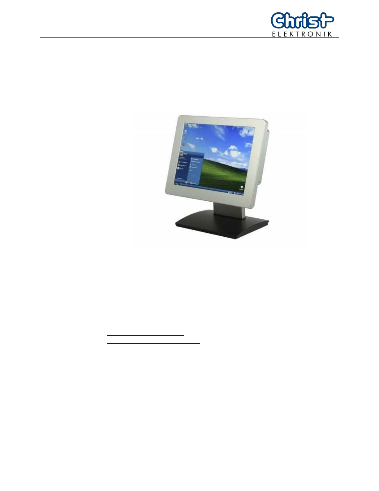
Operating Instructions
Touch-Panel
Touch-it XPC
Document No. E461201
Revision 01
Date 22.09.2010
Address Christ-Elektronik GmbH
Alpenstraße 34
DE-87700 Memmingen
Telephone +49 (0)8331 8371 – 0
Fax +49 (0)8331 8371 – 99
E-Mail [email protected]
Internet http://www.christ-elektronik.de
Copyright No part of this documentation may in any form whatsoever be repro-
duced, nor used, copied or distributed by means of electronic systems
without previous written permission by Christ-Elektronik GmbH. The
translation into another language also requires a written permission. This
documentation may be exclusively entrusted to the owner of the installa-
tion or to the employees of Christ-Elektronik GmbH.
Technical changes Christ-Elektronik GmbH reserves the right to change specifications, exe-
cutions and technical data held within this document without prior notice.
Trademarks Brand and product names are trademarks or registered trademarks of
their respective owners.
Page 2

1 E461201
Table of contents
Page
1. Pointers..................................................................................................................2
1.1. Used symbols..........................................................................................................2
1.2. General pointers......................................................................................................2
1.3. Safety pointers ........................................................................................................2
2. General...................................................................................................................4
3. Housing Types.......................................................................................................5
3.1. VESA.......................................................................................................................5
3.2. Front Panel..............................................................................................................5
3.3. In Wall.....................................................................................................................6
3.4. Open Frame............................................................................................................6
4. Commissioning .....................................................................................................7
4.1. Equipment...............................................................................................................7
4.1.1. Power Supply for VESA Housing ............................................................................7
4.1.2. Fasting Clamp for Front Panel Housing..................................................................7
4.2. Connector Side .......................................................................................................7
4.3. Supply voltage application.......................................................................................8
5. Software.................................................................................................................9
5.1. System Test and Initialization..................................................................................9
5.2. System Configuration Verification...........................................................................9
5.3. Award BIOS Setup..................................................................................................9
5.3.1. Changing Display Resolution ................................................................................10
5.3.2. Changing Boot Priority ..........................................................................................10
6. Touch Panel Driver..............................................................................................11
7. Interfaces .............................................................................................................13
7.1. USB connection ....................................................................................................13
7.2. Ethernet (LAN) ......................................................................................................14
7.3. COM1 (EIA-232 interface).....................................................................................14
7.4. VGA.......................................................................................................................14
8. Maintenance and servicing ................................................................................15
8.1. Maintenance plan..................................................................................................15
8.2. Repairs..................................................................................................................15
8.3. Cleaning................................................................................................................15
9. Error treatment and Disturbance removal ........................................................16
10. Technical Specifications ....................................................................................17
11. Scale Drawing......................................................................................................19
11.1. VESA Housing ......................................................................................................19
11.2. Front Panel Housing..............................................................................................21
11.3. In Wall Housing.....................................................................................................25
11.4. Open Frame with Front-USB.................................................................................26
Page 3
E461201 2
T
T
T
o
o
o
u
u
u
c
c
c
h
h
h
-
-
-
i
i
i
t
t
t
X
X
X
P
P
P
C
C
C
1. Pointers
1.1. Used symbols
Symbols The following symbols are used in this instruction manual:
DANGER!
Denotes a direct threat of danger. Not observing this pointer may be life
threatening or lead to serious injuries.
CAUTION!
Denotes a possibly dangerous situation. Not observing this pointer can
cause minor injuries or lead to material damages.
INFORMATION!
Denotes application pointers and other useful information.
1.2. General pointers
INFORMATION!
This device was manufactured according to DIN EN ISO 9001 and left the
factory in a perfect state.
In order to maintain this state and to assure the safe operation, the user
must consider the pointers and warning remarks, which are contained in
this instruction manual.
1.3. Safety pointers
DANGER!
In the case of damage of the box, the line or any other part of the device,
disconnect it immediately from the supply voltage and shut it down.
Disconnect every connection line before opening the device.
Page 4
3 E461201
DANGER!
Only the qualified staffs are allowed to carry out the repairs. The incorrect
repair may lead to serious danger for the user.
Avoid any penetration of liquid or dust.
Do not expose the device to humidity for a long time!
Intended Use
These products are not designed, developed and produced for use,
which pose fatal risks and dangers that may cause death, injuries, serious physical impairments or other loss, if no exceptional security measures are ensured. Thus there are limitations for use in the monitoring of
nuclear reactions in nuclear power plants, flight control systems, air traffic
control, in the control of mass transportation, medical life support systems
and control of weapon systems.
CAUTION!
If the device is used for other purposes or incorrectly operated, Christ
Elektronik GmbH will not hold damages liable.
Do not operate the touch-sensitive surface of the screen with any abra-
sive or sharp-edged objects.
Do not clean it with detergents containing solvent or acid.
Protect the Touch-Panel against caustic chemicals and long solar radiation.
INFORMATION!
Please check immediately:
Is the device damaged or is any equipment missing (see chapter 4.1.)?
In the case of defect please inform us immediately.
Page 5
E461201 4
T
T
T
o
o
o
u
u
u
c
c
c
h
h
h
-
-
-
i
i
i
t
t
t
X
X
X
P
P
P
C
C
C
2. General
This instruction manual concerns the following Touch-Panel version:
1. Series Type
Touch-it XPC
2. Housing Type Installation
Vesa desk stand, surface mounting
Front Panel fastening clamp
In Wall in the wall
Open Frame for dashboard
3. Display Screen size Native resolution
10,4“ (26,4 cm) 800 x 600, 1024 x 768
15,0” (38,1 cm) 1024 x 768
Technology Colours
TFT 262.000
4. Backlight
1 CCFL switched
2 CCFL controlled
3 LED
5. Processor Type Frequency
Intel Atom N270 1,6 GHz, FSB 533 MHz
6. Chipset
Intel® 945GSE + ICH7M
7. Memory
RAM 2 GB, DDRII
8. Storage
Compact Flash 8 GB, 133x
Hard Disk Drive 250 GB, 2,5”, SATA
9. Operation
F Foil touch
Table 1: overview Touch-it XPC
Please refer to the order number for further information.
Page 6
5 E461201
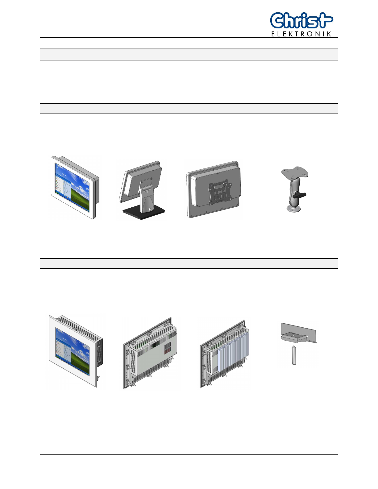
3. Housing Types
In order to mount the touch panel, the following variants are available:
3.1. VESA
Picture 1: VESA mounting variants
front view desk stand surface mounting individual holder-system
3.2. Front Panel
Picture 2: Front Panel mounting
front view with fan fanless fasting clamp
Page 7
E461201 6
T
T
T
o
o
o
u
u
u
c
c
c
h
h
h
-
-
-
i
i
i
t
t
t
X
X
X
P
P
P
C
C
C
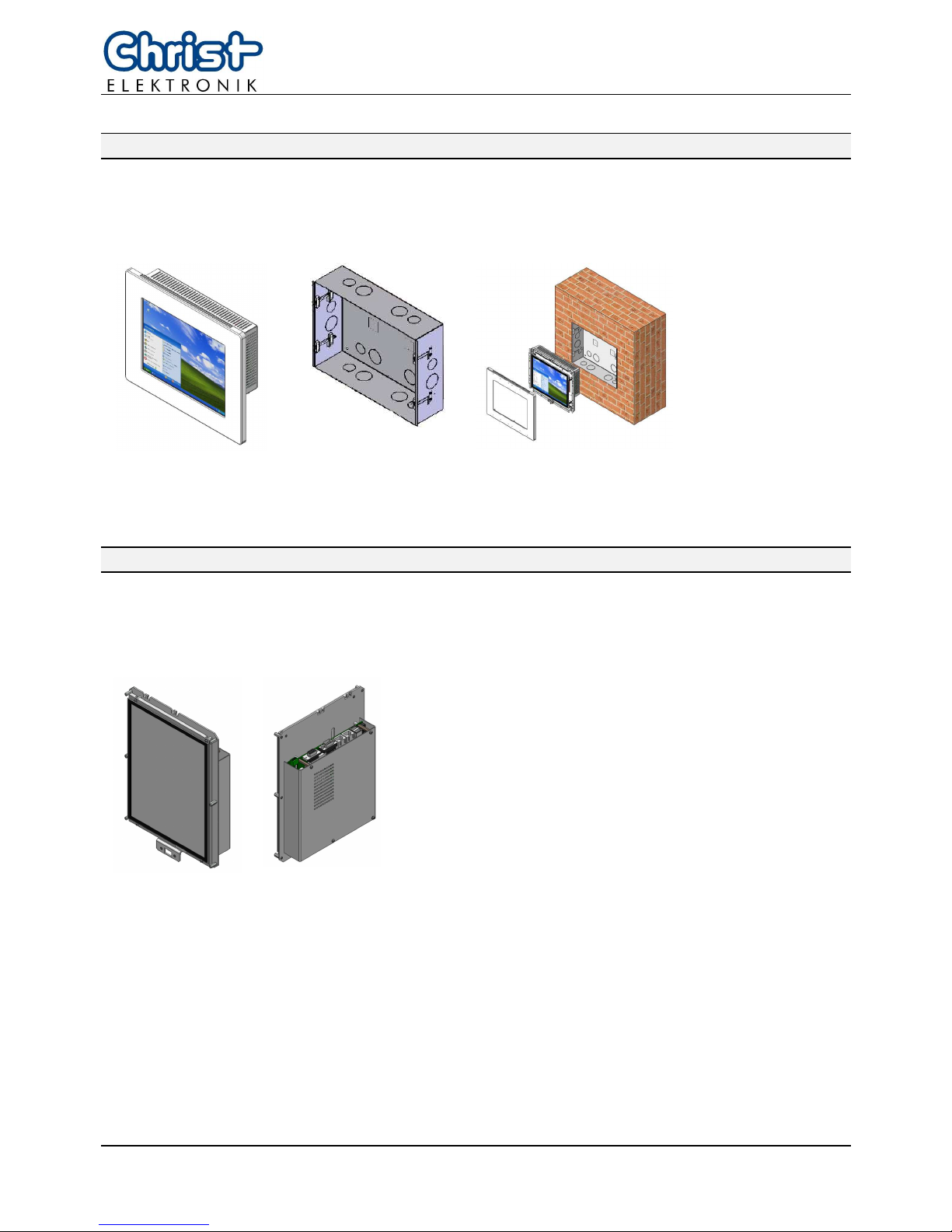
3.3. In Wall
Picture 3: wall mounting housing
front view box in the wall
3.4. Open Frame
Picture 4: open frame (with front USB)
front view reverse view
Page 8
7 E461201
4. Commissioning
4.1. Equipment
The Touch-Panel contains the following equipment:
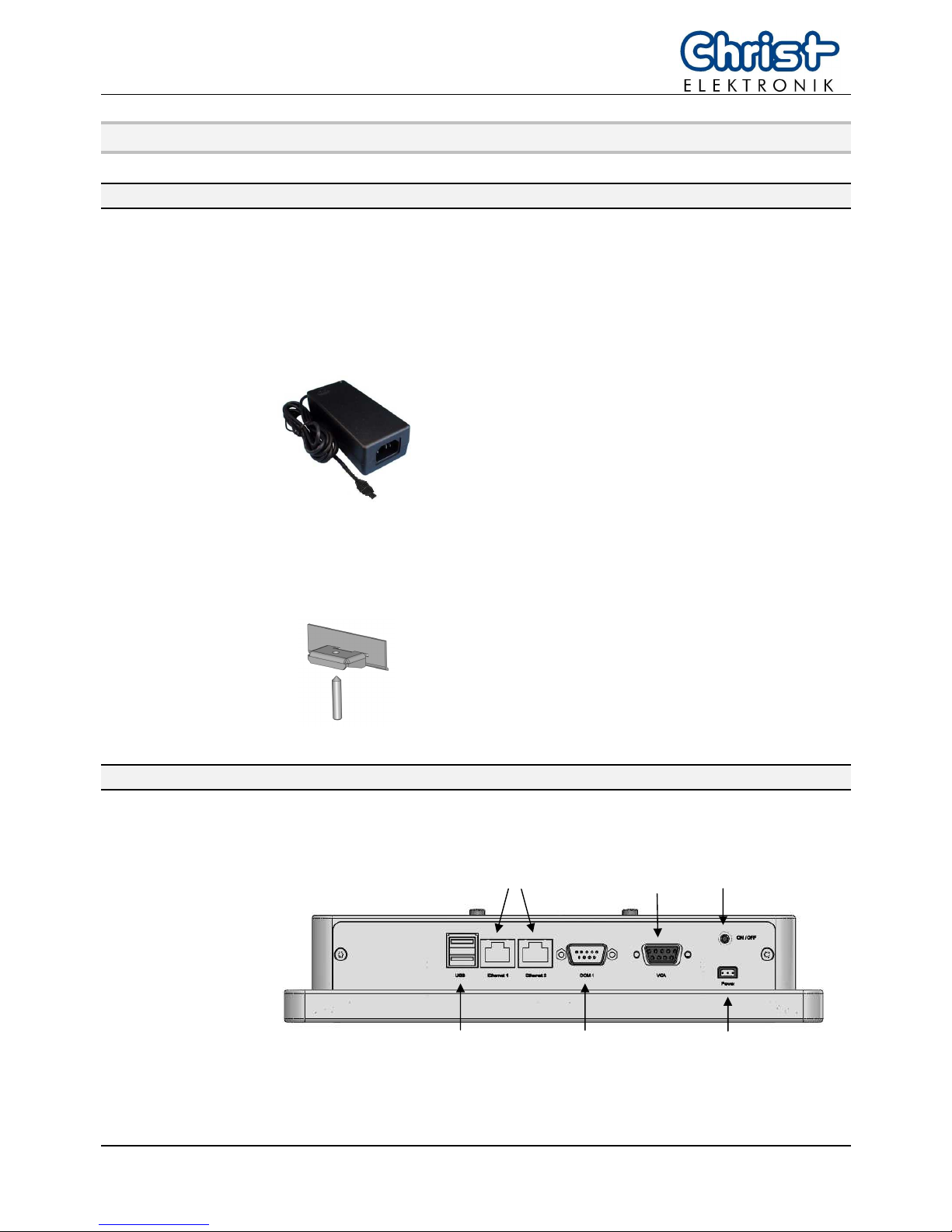
4.1.1. Power Supply for VESA Housing
Picture 5: power supply
The Touch-it XPC VESA housing needs a power
supply with Hirose connector (see chapter 4.3).
A 24VDC power supply is included in the delivery.
4.1.2. Fasting Clamp for Front Panel Housing
Picture 6: fasting clamp
Before you begin installing the Touch-Panel, into
front panel please make sure that the
10 clamps with setscrews have been shipped.
4.2. Connector Side
Picture 7: connector side Touch-it XPC VESA housing
The interfaces are described in the chapter 7.
Supply
voltage
Switch
ON/OFF
USB
COM1
EIA-232
Ethernet
VGA
Page 9
E461201 8
T
T
T
o
o
o
u
u
u
c
c
c
h
h
h
-
-
-
i
i
i
t
t
t
X
X
X
P
P
P
C
C
C
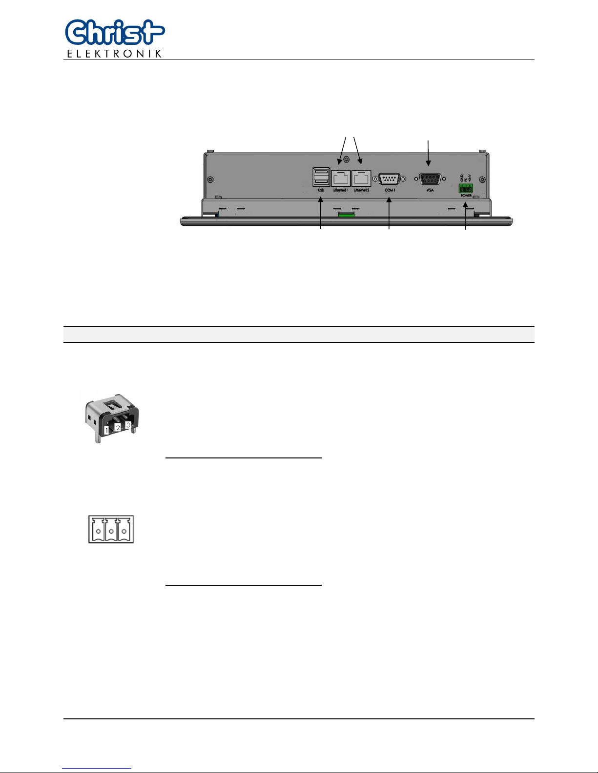
Picture 8: connector side Touch-it XPC In Wall/ Front Panel housing
The interfaces are described in the chapter 7.
4.3. Supply voltage application
Picture 9: connection supply voltage VESA housing
Pin 1: 24 V
DC nominal
Pin 2: PE
Pin 3: GND
Mating with power supply plugs:
Hirose connectors RP34L-5PA-3SC or RP34L-5LP-3SC
1 2 3
Picture 10: connection supply voltage for all housing types but VESA
Pin 1: GND
Pin 2: PE
Pin 3: 24 V
DC nominal
Mating with power supply plugs:
phoenix connector MC 1,5/ 3-ST-3,5 BK
USB COM1
EIA-232
Ethernet
VGA
Supply
voltage
Page 10

9 E461201
5. Software
5.1. System Test and Initialization
These routines test and initialize board hardware. If the routines encounter an error during the
tests, you will either hear a few short beeps or see an error message on the screen. There are
two kinds of errors: fatal and non-fatal. The system can usually continue the boot up sequence
with non-fatal errors. Non-fatal error messages usually appear on the screen along with the following instructions:
Press “F1” to RESUME
Write down the message and press the “F1” key to continue the boot up sequence.
5.2. System Configuration Verification
These routines check the current system configuration against the values stored in the CMOS
memory. If they do not match, the program outputs an error message. You will then need to run
the BIOS setup program to set the configuration information in memory.
There are three situations in which you will need to change the CMOS settings:
1. You are starting your system for the first time
2. You have changed the hardware attached to your system
3. The CMOS memory has lost power and the configuration information has been erased.
The XPC Device CMOS memory has an integral lithium battery backup for data retention.
5.3. Award BIOS Setup
Awards BIOS ROM has a built-in Setup program that allows users to modify the basic system
configuration. This type of information is stored in battery-backed CMOS RAM so that it retains
the Setup information when the power is turned off.
Entering Setup
Power on the computer and press “Del” immediately. This will allow you to enter Setup.
Standard CMOS Features
Use this menu for basic system configuration. (Date, time, IDE, etc.)
Advanced BIOS Features
Use this menu to set the advanced features available on your system.
Advanced Chipset Features
Use this menu to change the values in the chipset registers and optimize your system performance.
Page 11

E461201 10
T
T
T
o
o
o
u
u
u
c
c
c
h
h
h
-
-
-
i
i
i
t
t
t
X
X
X
P
P
P
C
C
C
Integrated Peripherals
Use this menu to specify your settings for integrated peripherals.
(Primary slave, secondary slave, keyboard, mouse etc.)
Power Management Setup
Use this menu to specify your settings for power management.
(HDD power down, power on by ring, KB wake up, etc.)
5.3.1. Changing Display Resolution
Once in the Setup mode choose the [Advanced Chipset Features]
Menu and set the Internal LVDS as follows:
10.4” Display -> 800x600, 1024x768
15.0” Display -> 1024x768
Save this configuration by pressing the “F10” and afterwards “Y”.
5.3.2. Changing Boot Priority
In order to boot from a USB Drive the following settings must be done.
Once in the Setup mode choose the [Advanced BIOS Features] Menu
and set the Hard Disk Boot Priority in such a way that the
USB-HDD0 Device is first in the boot list.
This can be done using the Page-Up/Down Keys.
Save this configuration by pressing the “F10” and afterwards “Y”.
Page 12
11 E461201
6. Touch Panel Driver
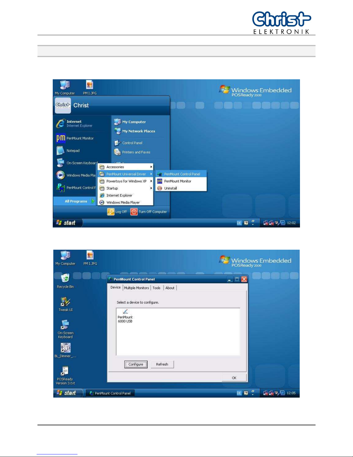
1. Click on [Start] [All Programs] [Pen Mount Universal Driver] [Pen Mount Control Panel]
2. Click on [Pen Mount 6000 USB]
Page 13
E461201 12
T
T
T
o
o
o
u
u
u
c
c
c
h
h
h
-
-
-
i
i
i
t
t
t
X
X
X
P
P
P
C
C
C
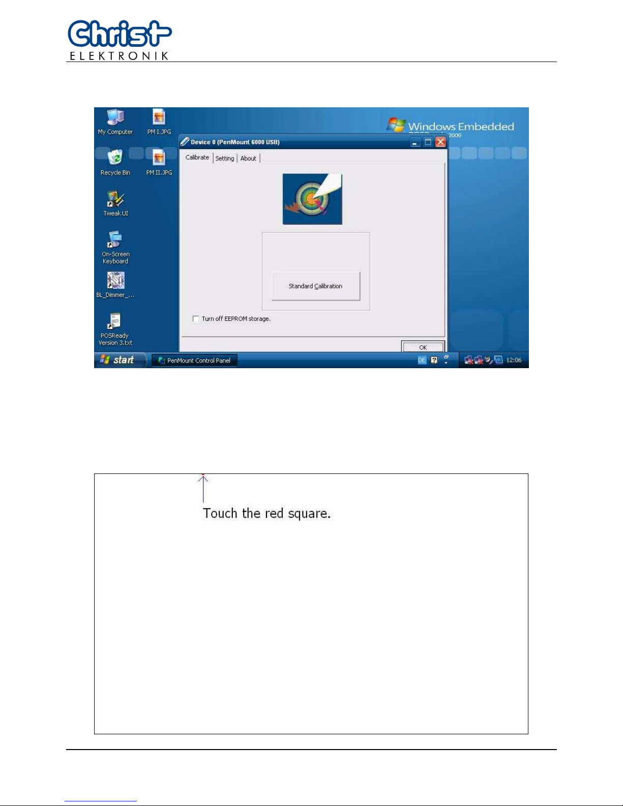
3. Click on [Standard Calibration]
4. Pressing the [Standard Calibration] button on the main window activates the calibration
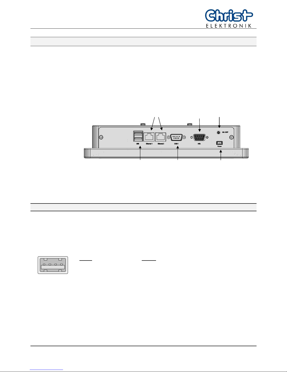
screen to carry out calibration of the Touch Panel.
Briefly touch the centre of the red square splayed on the screen in order as they appear.
Once calibration is carried out, the calibrated value is saved. Since the calibrated value is
read from the setting file at the time of the next start up, there is no need to carry out calibration again.
Page 14
13 E461201
7. Interfaces
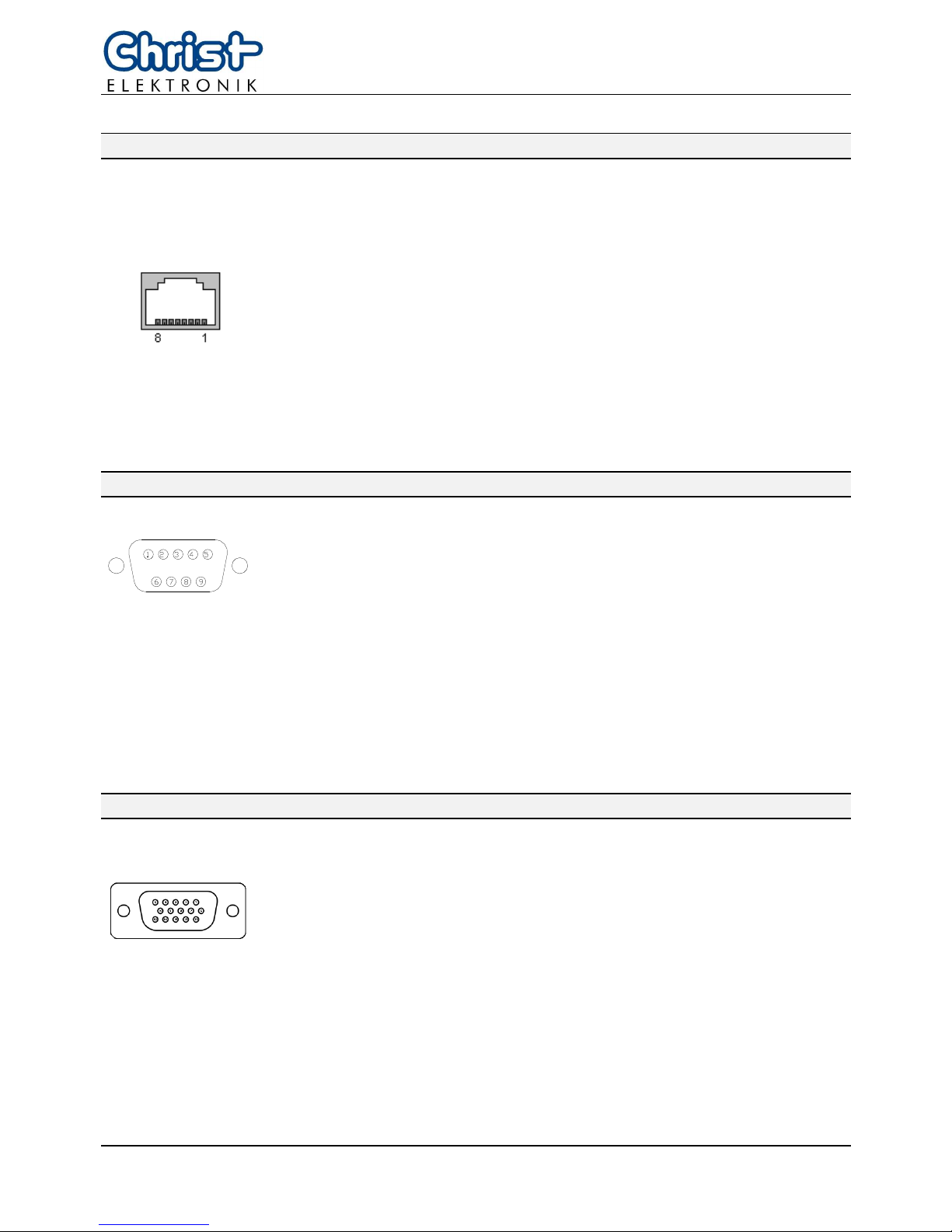
The following interfaces are available:
• USB2.0
• Ethernet (LAN, 2x)
• COM
(
EIA-232)
• VGA
Picture 11: connector side Touch-it XPC
Connection of the supply voltage, see chapter 4.3.
7.1. USB connection
The Touch-it XPC offers two USB ports. The USB connections are pro-
vided for the connection of storage media as well as peripheral equipment (USB Mouse or Keyboard).
4 3 2 1
Picture 12: USB Port 1, 2 Connector
Port1: Port2:
pin 1: +5V pin 1: +5V
pin 2: Data0 – pin 2: Data1 –
pin 3: Data0 + pin 3: Data1 +
pin 4: GND pin 4: GND
Supply
voltage
Switch
ON/OFF
USB
COM1
EIA-232
Ethernet
VGA
Page 15
E461201 14
T
T
T
o
o
o
u
u
u
c
c
c
h
h
h
-
-
-
i
i
i
t
t
t
X
X
X
P
P
P
C
C
C
7.2. Ethernet (LAN)
The connection to an Ethernet network (10/100/1000BASE-TX) is carried
out with a RJ45 socket. It is recommended to use a CAT. 5 cable or
higher for the connection to the network.
Picture 13: pin assignment Ethernet (RJ45 socket)
pin 1: D1+ pin 5: D3-
pin 2: D1- pin 6: D2pin 3: D2+ pin 7: D4+
pin 4: D3+ pin 8: D4-
The Touch-it XPC offers two Ethernet network interfaces.
7.3. COM1 (EIA-232 interface)
Picture 14: pin assignment EIA-232 interface (DB9 male socket)
COM1
pin 1: DCD pin 6: DSR
pin 2: RX pin 7: RTS
pin 3: TX pin 8: CTS
pin 4: DTR pin 9: RI
pin 5: GND
7.4. VGA
Picture 15: pin assignment monitor interface
VGA
pin 1: red pin 6: GND pin 11: ID0
pin 2: green pin 7: GND pin 12: DDC DATA
pin 3: blue pin 8: GND pin 13: H_SYNC
pin 4: n. c. pin 9: +5V pin 14: V_SYNC
pin 5: GND pin 10: GND pin 15: DDC CLK
Page 16
15 E461201
8. Maintenance and servicing
8.1. Maintenance plan
INFORMATION!
Only the manufacturer (Christ-Elektronik GmbH) is allowed to replace the
internal lithium battery.
The calibration of the touch may be required from time to time.
8.2. Repairs
DANGER!
Only the qualified staffs are allowed to carry out the repairs. The incorrect
repair may lead to serious danger for the user.
8.3. Cleaning
DANGER!
Disconnect the Touch-Panel from the supply voltage before cleaning.
CAUTION!
Do not clean the touch-sensitive surface of the monitor with detergents
containing solvent or acid.
INFORMATION!
Use a humid and soft cloth with gentle soapsuds to clean.
Page 17
E461201 16
T
T
T
o
o
o
u
u
u
c
c
c
h
h
h
-
-
-
i
i
i
t
t
t
X
X
X
P
P
P
C
C
C
9. Error treatment and Disturbance removal
Error Cause Remedy
Touch-Panel does not
function
Wrong voltage supply
Use adequate power supply unit
24 V DC
Application download
not possible anymore
Voltage failure during a
download. This could damage
the bootloader.
Send the Touch-Panel for check
to Christ-Elektronik
Touch surface damaged
Send the Touch-Panel for repair
to Christ-Elektronik GmbH
Touch point displaced,
which means the pressure point and the indication field are not one
above the other
Wrong calibration
Calibrate the Touch-Panel
Clock does not work Battery empty Only the manufacturer (Christ-
Elektronik GmbH) is allowed to
replace the internal lithium battery
Operating system does
not boot up
CF card damaged or the file system is corrupt
Contact Christ-
Elektronik GmbH or
your supplier
If any disturbance occurs in the Touch-Panel, please contact your supplier or our customer
service department:
Page 18
17 E461201
10. Technical Specifications
Touch-it XPC 104 150
Display
Screen Size
10,4“ (26,4 cm) 15” (38,1 cm)
Display Dimensions [mm]
215 x 162 304 x 228
Native Resolution (Pixel)
800 x 600, 1024 x 768 1024 x 768
Technology
TFT
Colours
262.144
Backlight
LED CCFL
Luminance [cd/m²]
350
Operation
Operation
Touch
Touch Technology
analogue, resistive foil touch
System
Processor
Intel
®
Atom™ N270 1,6 GHz
Memory
2 GB DDRII RAM
Storage
Compact Flash (8GB, 133x),
Hard Disk Drive (250GB, 2,5” SATA)
Operating System
Microsoft® Windows® XP Embedded Standard, Linux on request
Supplied Software
IIS Components, Page File Support, Enhanced Write Filter - RAM / API,
EWF Manager Console, EWF NTLDR, System Restore, On-Screen Keyboard,
German / English Language Support, Media Player 11, …
Interfaces
USB
2 x USB2.0 Typ A
LAN
10/100/1000 MBit Ethernet (RJ45 x 2)
Serial Port
EIA-232
VGA
monitor port (DB15)
Audio (optional)
Line In, Line Out, Mic-In
Power Supply
Supply Voltage (nominal)
24 V DC
Voltage domain
12 – 36 V DC
Power (nominal) [W]
24 30
Dimensions
VESA Housing
- Front (B x H) [mm]
264 x 209 361 x 288
- Box [mm]
237 x 137 283 x 210
- Depth [mm]
55 60
WALL / Front Panel Housing
- Front (B x H) [mm]
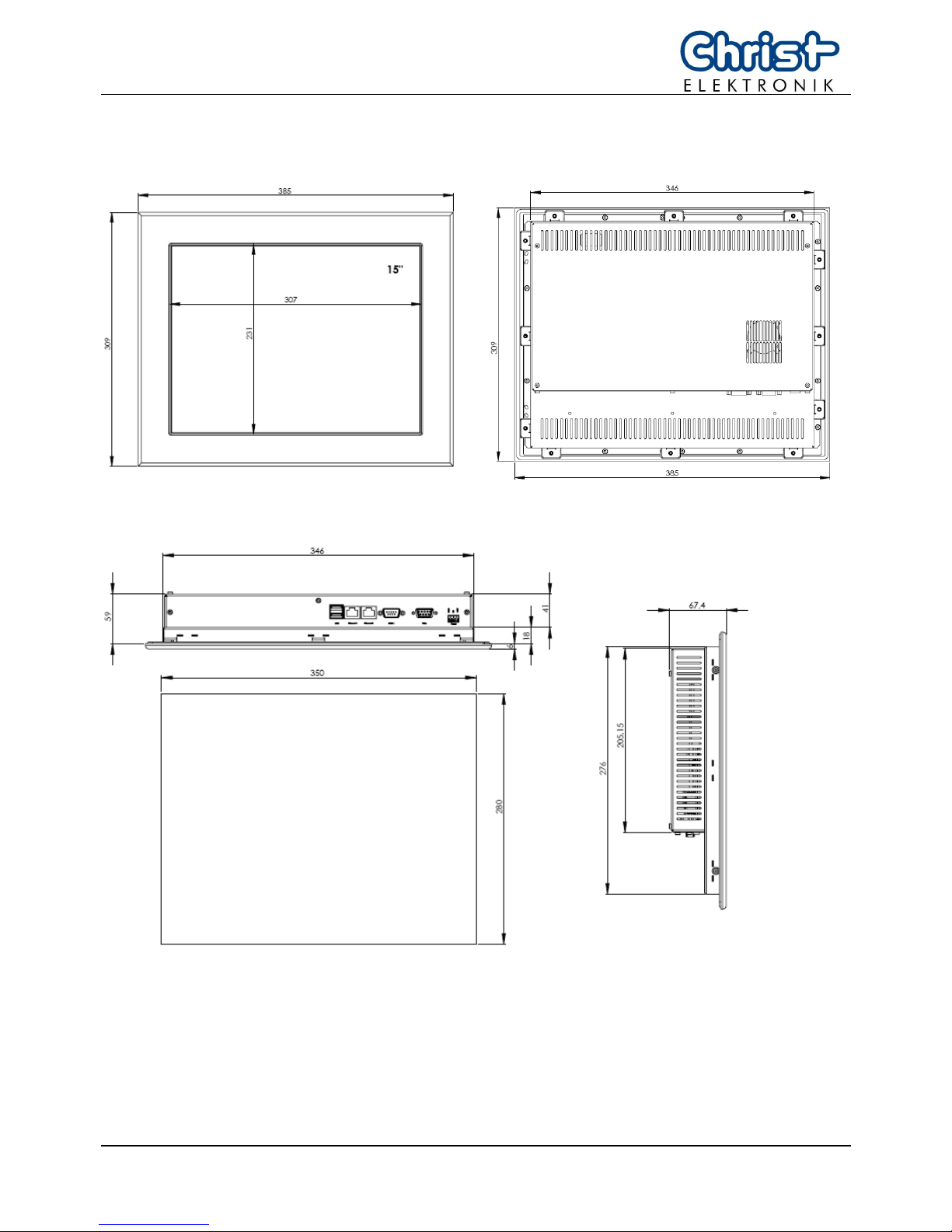
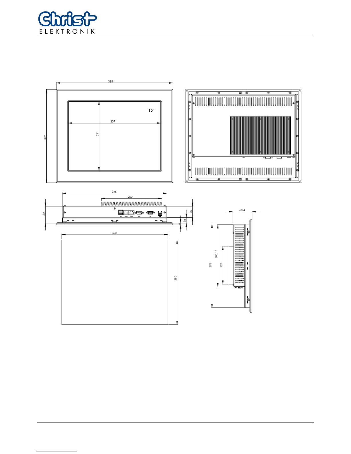
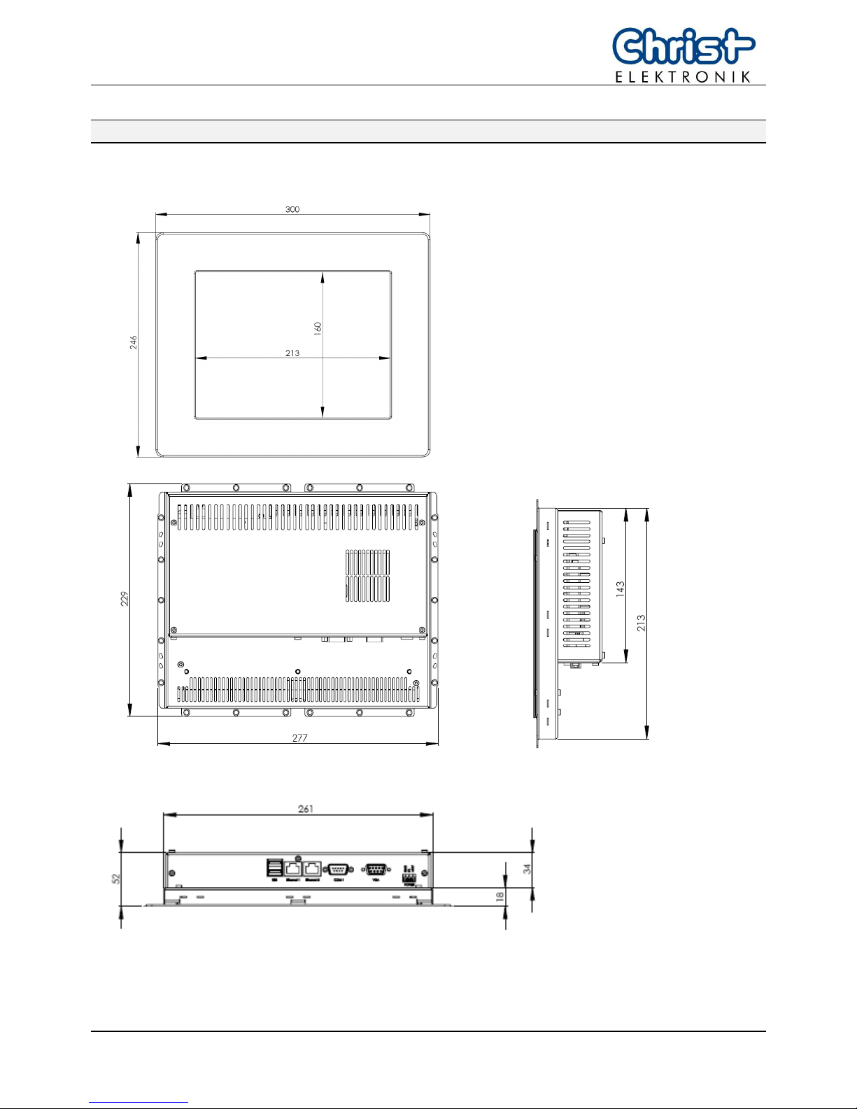
300 x 246 385 x 309
- Box [mm]
261 x 213 346 x 276
- Installation Depth
with fan [mm]
59 59
- Installation Depth
fanless [mm]
67 67
- Installation Aperture [mm]
265 x 217 350 x 280
Page 19
E461201 18
T
T
T
o
o
o
u
u
u
c
c
c
h
h
h
-
-
-
i
i
i
t
t
t
X
X
X
P
P
P
C
C
C
Touch-it XPC 104 150
Material
Front
anodised aluminium
Chassis (wall, front panel)
galvanised metal
Chassis VESA
anodised aluminium
Weight [kg]
2,5 4,6
User Environment
Operating Temperature
0 to +50 °C
Storage Temperature
-10 to +70 °C
Humidity
5% to 80% (non condensing)
Degree of Protection (Front)
IP 65
Degree of Protection
(Chassis)
IP 20
Certification
CE, EN55022, EN55024, EN60950-1, DIN EN ISO 9001
This is a Class A product. In a domestic environment this product may cause radio
interference, in which case the user may be required to take adequate measures.
Page 20
19 E461201
11. Scale Drawing
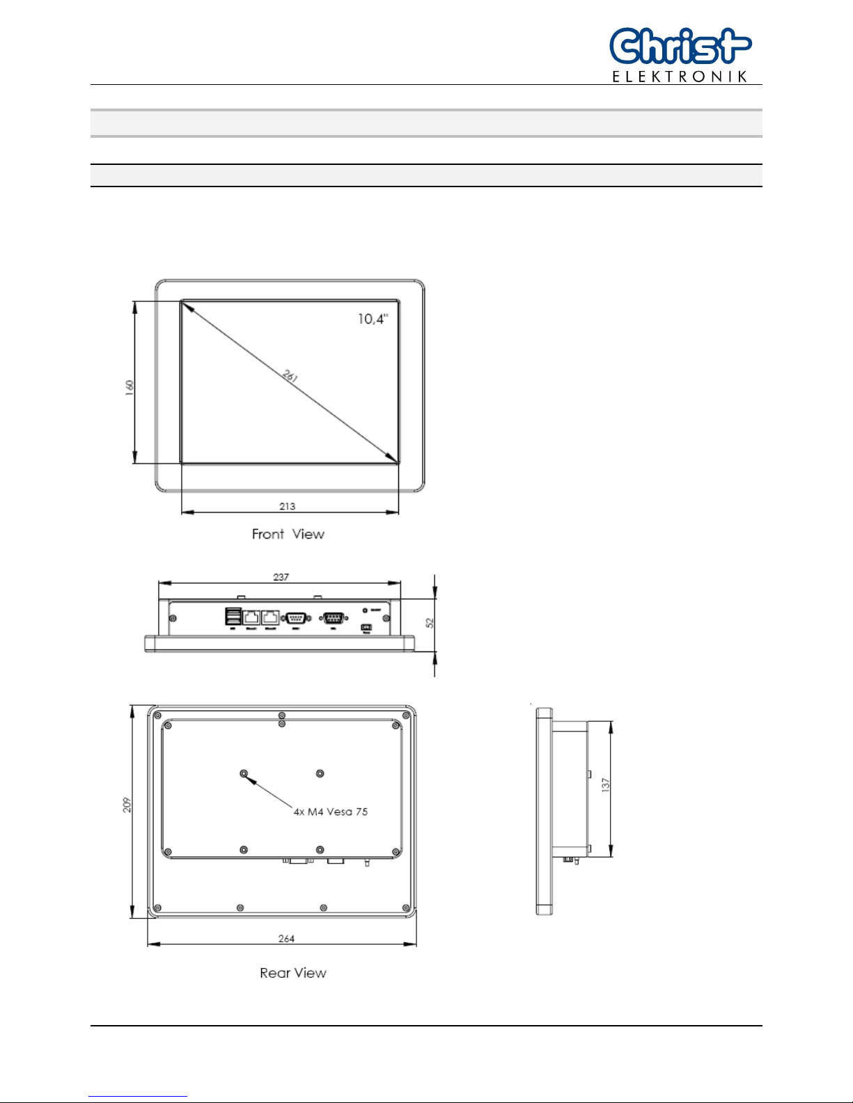
11.1. VESA Housing
Picture 16: dimensions Touch-it XPC 10,4”
Page 21
E461201 20
T
T
T
o
o
o
u
u
u
c
c
c
h
h
h
-
-
-
i
i
i
t
t
t
X
X
X
P
P
P
C
C
C
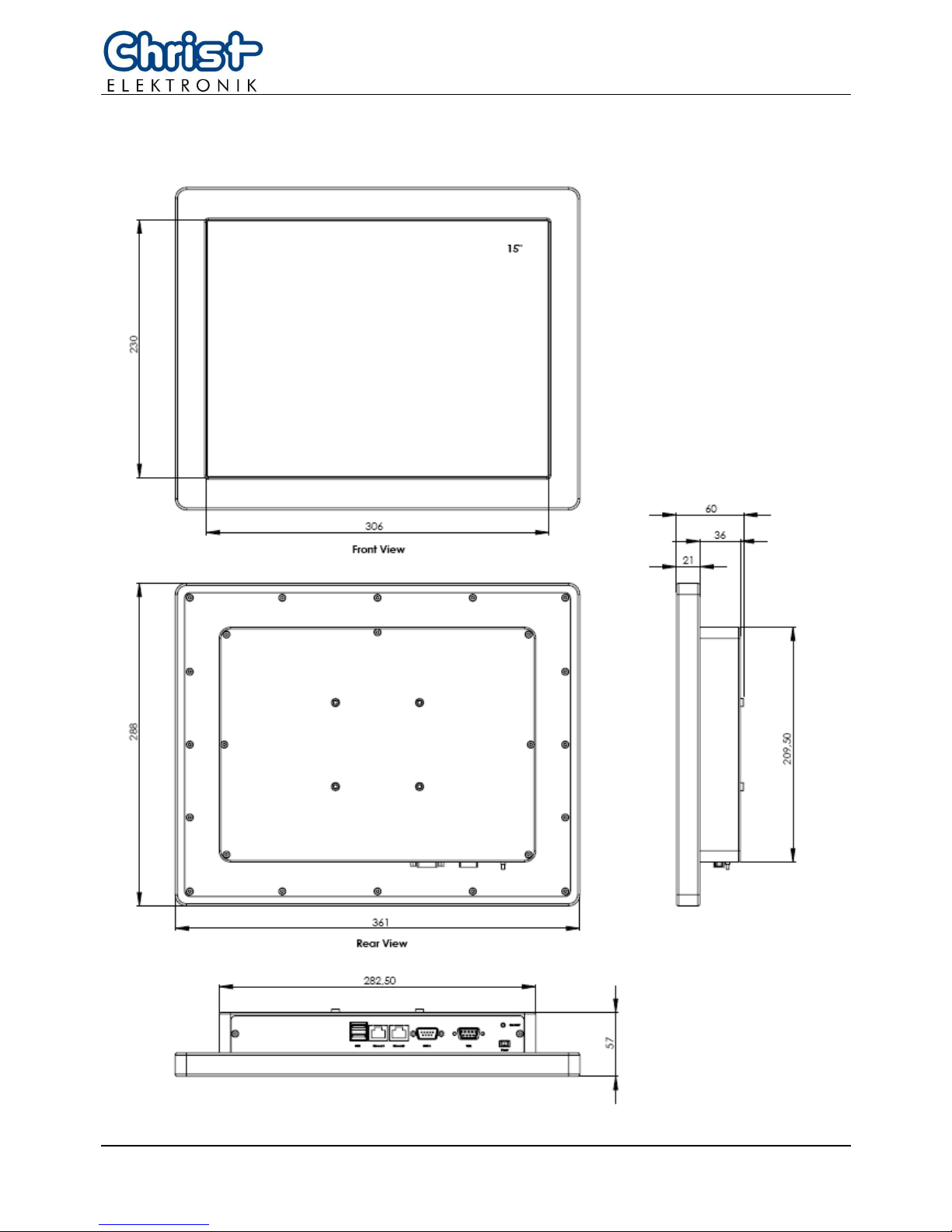
Picture 17: dimensions Touch-it XPC 15”
Page 22
21 E461201
11.2. Front Panel Housing
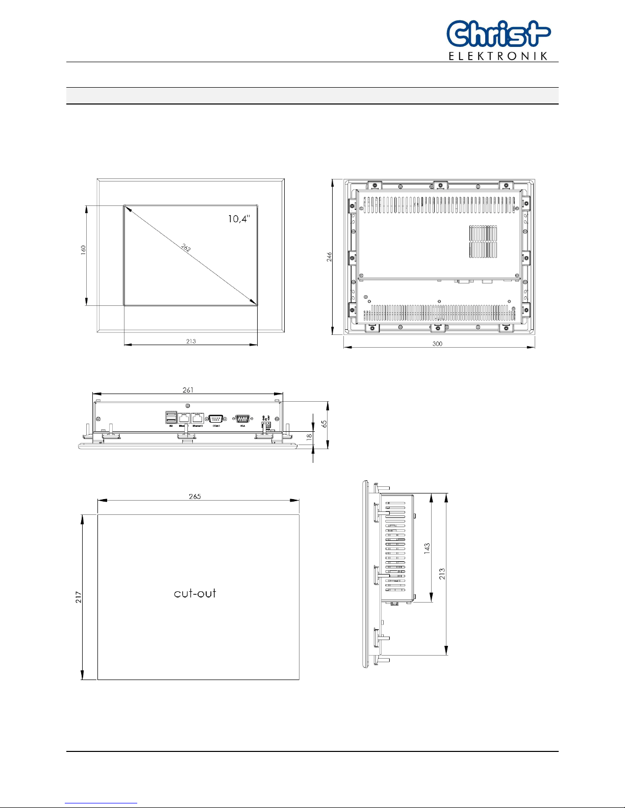
Picture 18: dimensions Touch-it XPC 10,4” with fan
Page 23
E461201 22
T
T
T
o
o
o
u
u
u
c
c
c
h
h
h
-
-
-
i
i
i
t
t
t
X
X
X
P
P
P
C
C
C
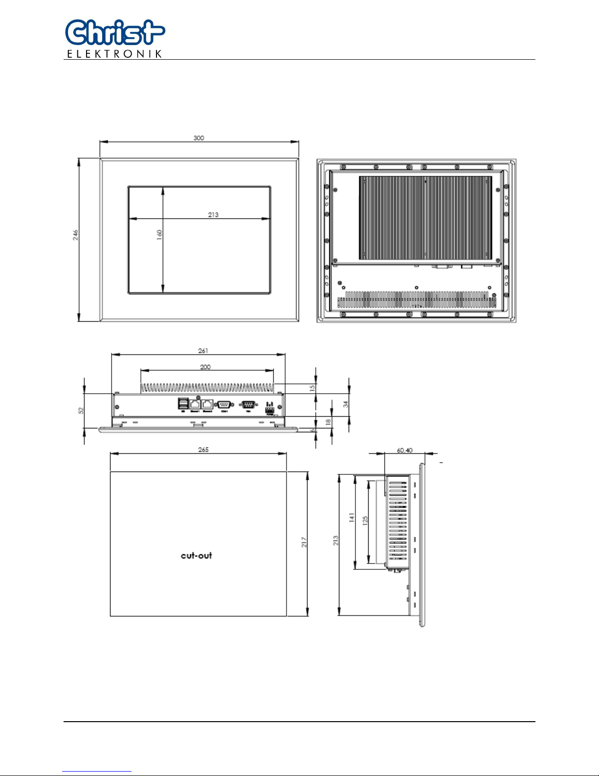
Picture 19: dimensions Touch-it XPC 10,4” fanless
Page 24
23 E461201
Picture 20: dimensions Touch-it XPC 15” with fan
Page 25
E461201 24
T
T
T
o
o
o
u
u
u
c
c
c
h
h
h
-
-
-
i
i
i
t
t
t
X
X
X
P
P
P
C
C
C
Picture 21: dimensions Touch-it XPC 15” fanless
Page 26
25 E461201
11.3. In Wall Housing
Picture 22: dimensions Touch-it XPC 10,4”
Page 27
E461201 26
T
T
T
o
o
o
u
u
u
c
c
c
h
h
h
-
-
-
i
i
i
t
t
t
X
X
X
P
P
P
C
C
C
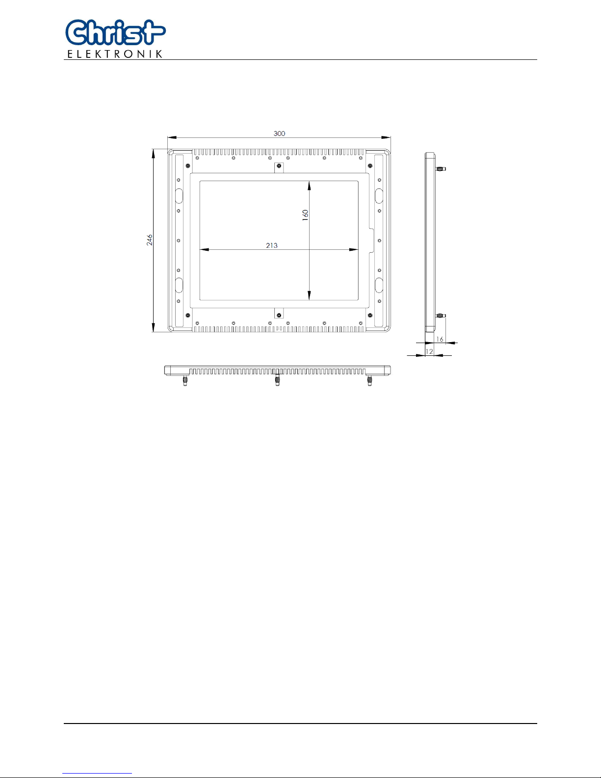
Picture 23: dimensions front frame for Touch-it XPC 10,4”
Page 28
27 E461201
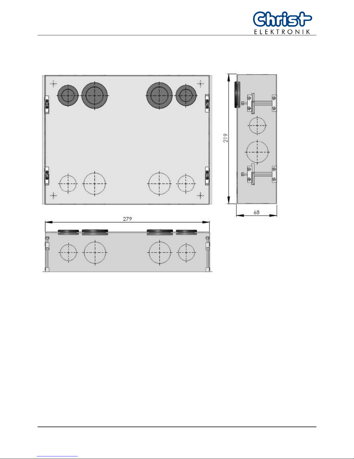
Picture 24: dimensions In Wall Box for Touch-it XPC 10,4”
Page 29
E461201 28
T
T
T
o
o
o
u
u
u
c
c
c
h
h
h
-
-
-
i
i
i
t
t
t
X
X
X
P
P
P
C
C
C
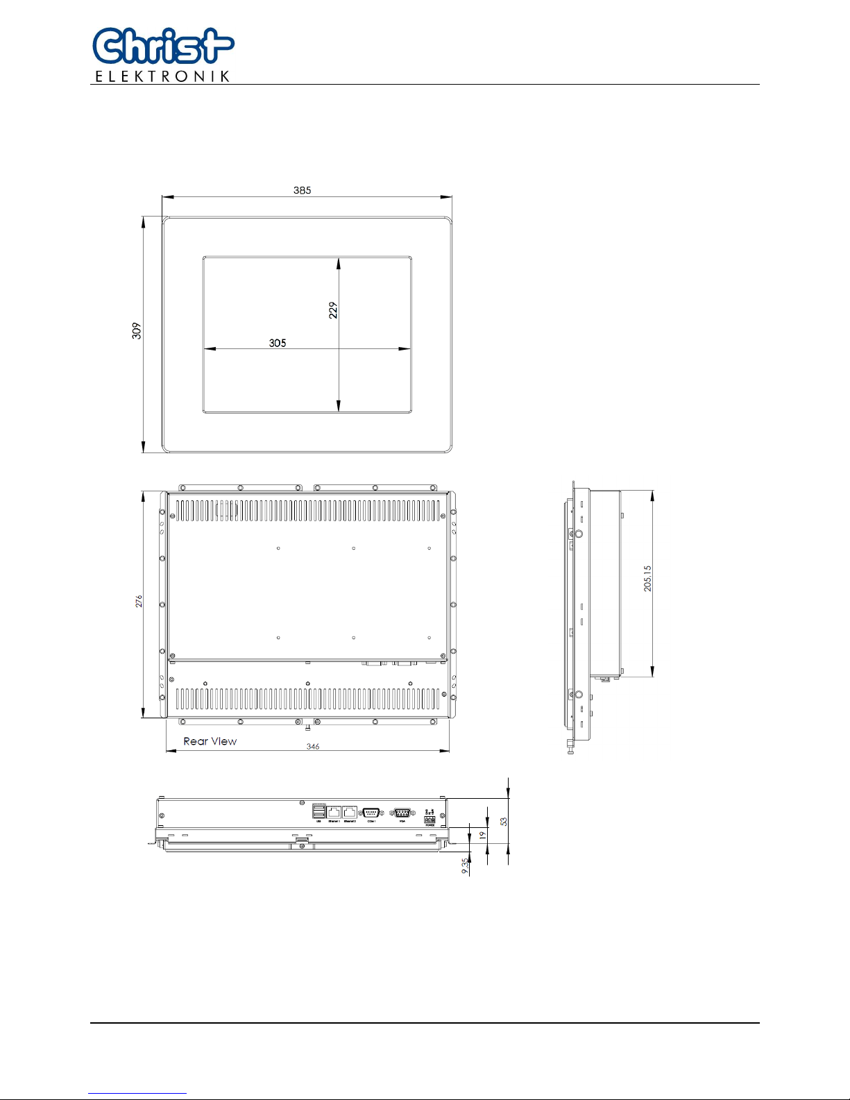
Picture 25: dimensions Touch-it XPC 15”
Page 30
29 E461201
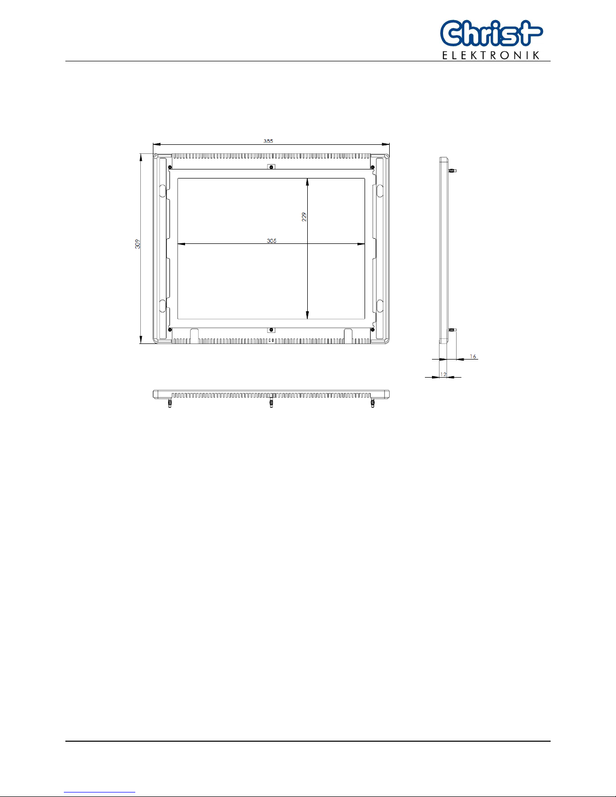
Picture 26: dimensions front frame for Touch-it XPC 15”
Page 31
E461201 30
T
T
T
o
o
o
u
u
u
c
c
c
h
h
h
-
-
-
i
i
i
t
t
t
X
X
X
P
P
P
C
C
C
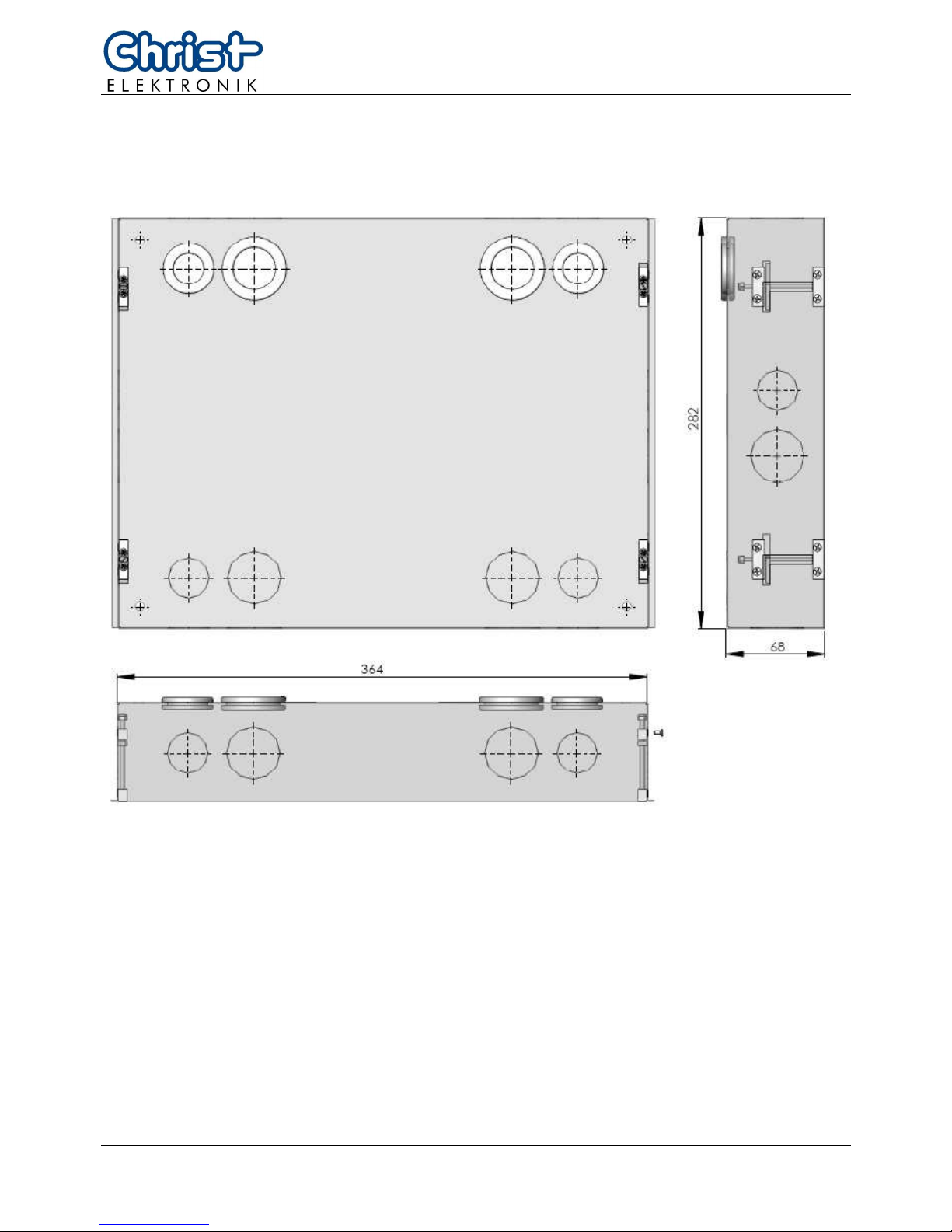
Picture 27: dimensions In Wall Box for Touch-it XPC 15”
Page 32
31 E461201
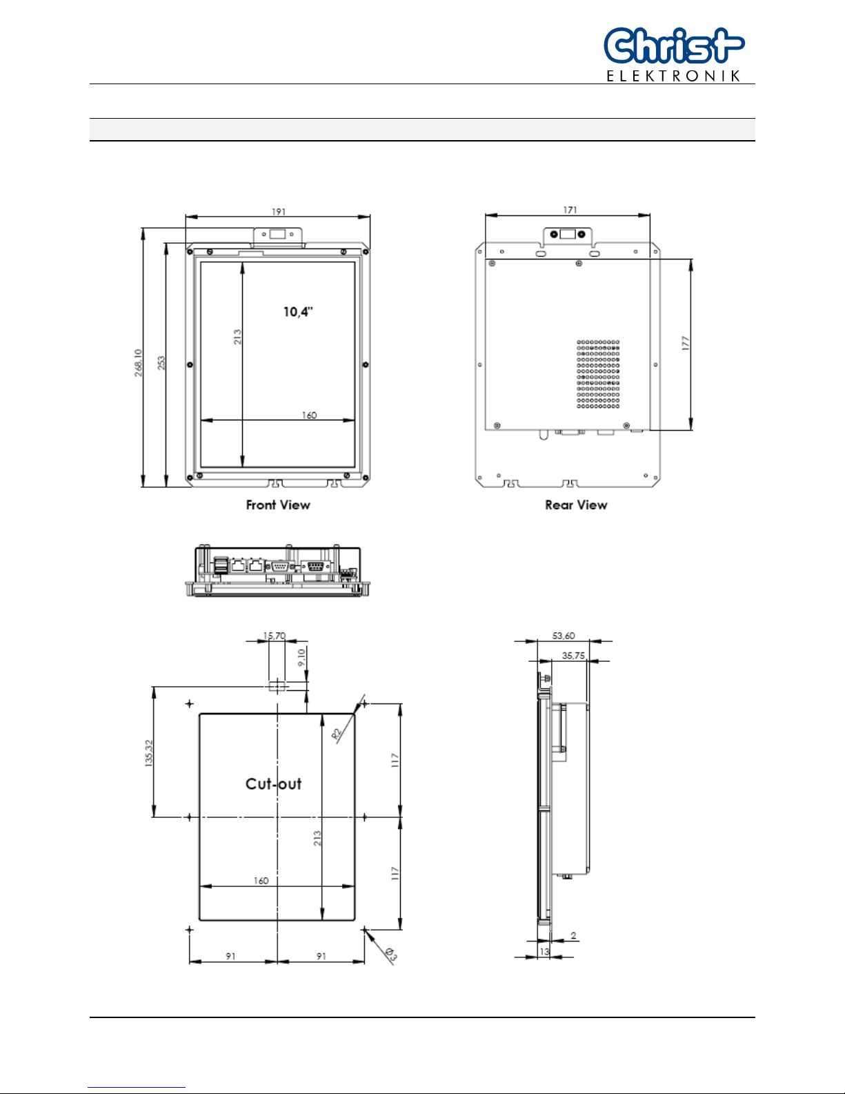
11.4. Open Frame with Front-USB
Picture 28: dimensions Touch-it XPC 10,4”
 Loading...