

Page 1
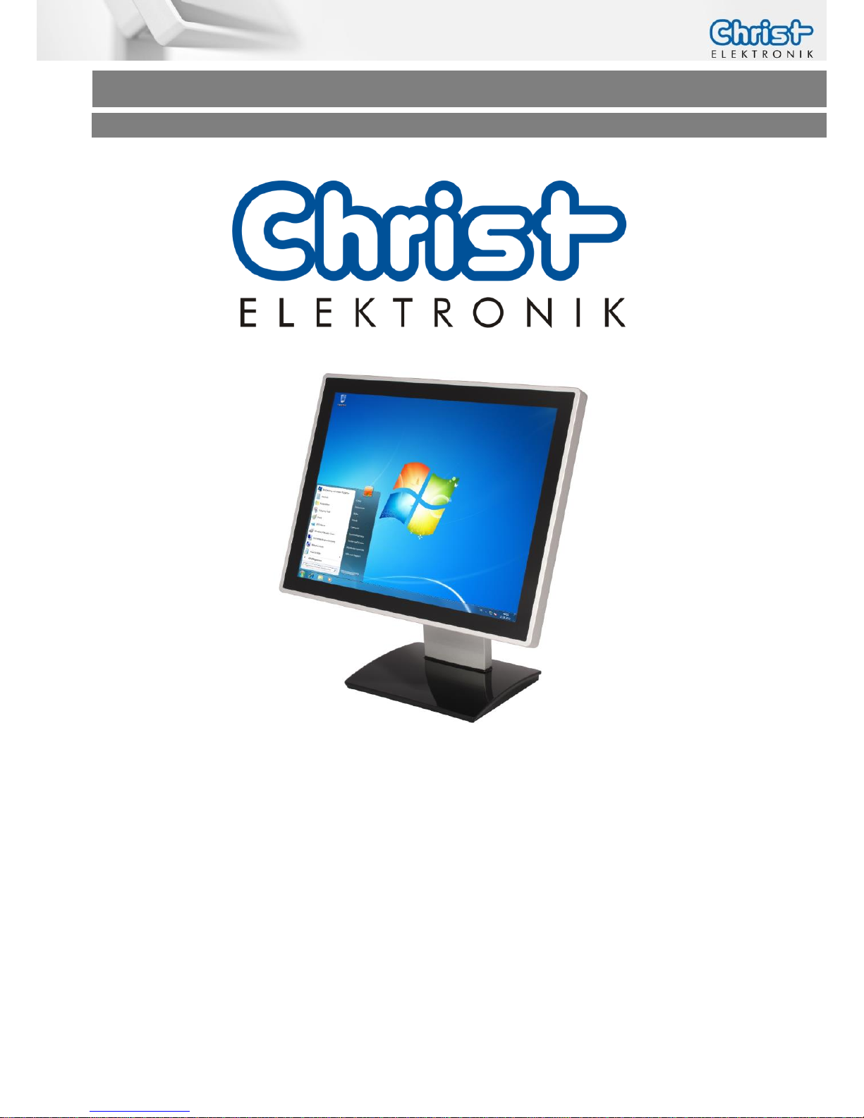
Touch-it XELO
Operating Instructions
Copyright / © Christ-Elektronik GmbH 1 / 44 Sep. 2015, Revision 12
a member of the Christ Company Group Document No.: E461201
Touch-it XELO
Touch Interface
Different Housings
Sizes From 7” to 21.5”
Ready For Use Touch Panel PC
Page 2
Touch-it XELO
Operating Instructions
Copyright / © Christ-Elektronik GmbH 2 / 44 Sep. 2015, Revision 12
a member of the Christ Company Group Document No.: E461201
Document No.
E461201
Revision
12
Date
24 Sep. 15
Address
Christ-Elektronik GmbH
Alpenstraße 34
DE-87700 Memmingen
Telephone
+49 (0)8331 8371 – 0
Fax
+49 (0)8331 8371 – 99
E-Mail
Internet
http://www.christ-elektronik.de
Copyright
No part of this documentation may in any form be reproduced, copied or
distributed by means of electronic systems without previous written permission by Christ-Elektronik GmbH. The translation into another language also requires a written permission. This documentation may be
exclusively entrusted to the owner of the installation or to the employees
of Christ-Elektronik GmbH.
Technical changes
Christ-Elektronik GmbH reserves the right to change specifications, executions and technical data held within this document without prior notice.
Trademarks
Brand and product names are trademarks or registered trademarks of
their respective owners.
Page 3

Touch-it XELO
Operating Instructions
Copyright / © Christ-Elektronik GmbH 3 / 44 Sep. 2015, Revision 12
a member of the Christ Company Group Document No.: E461201
Table of contents
Page
1 General................................................................................................................................................5
2 Commissioning ..................................................................................................................................8
2.1 Mounting ............................................................................................................................................... 8
2.1.1 Touch-it XELO Open Frame / Open Frame glass ........................................................................................................ 8
2.1.2 Touch-it XELO Front Panel / Front Panel glass ............................................................................................................ 9
2.1.3 Touch-it XELO VESA / VESA glass .................................................................................................................................. 10
2.2 Interfaces Connector Side (CPU N270 / T56N) ..................................................................... 11
2.3 Interfaces Connector Side (CPU GX-415GA / i5-5300U) .................................................... 12
3 Software ...........................................................................................................................................13
3.1 Award BIOS Setup (CPU N270) ................................................................................................... 13
3.1.1 Changing Display Resolution .......................................................................................................................................... 14
3.1.2 Changing Boot Priority ....................................................................................................................................................... 14
3.2 American Megatrends, Inc. (AMI) BIOS Setup (CPU T56N) ............................................... 15
3.2.1 Changing Display Resolution .......................................................................................................................................... 16
3.2.2 Changing Boot Priority ....................................................................................................................................................... 16
3.3 American Megatrends, Inc. (AMI) BIOS (CPU GX-415GA / i5-5300U) ......................... 17
3.3.1 Changing Display Resolution (CPU GX-415GA) ....................................................................................................... 18
3.3.2 Changing Display Resolution (CPU i5-4300U) .......................................................................................................... 18
3.3.3 Changing Boot Priority ....................................................................................................................................................... 18
3.3.4 Changing COM Port (CPU GX-415GA) ........................................................................................................................ 19
3.3.1 Changing COM Port (CPU i5-4300U) ........................................................................................................................... 19
3.4 Redo Backup and Recovery .......................................................................................................... 20
3.4.1 Generate bootable Redo Backup and Recovery USB stick .................................................................................. 20
3.4.2 Restoring an Image with Redo Backup and Recovery ........................................................................................... 22
3.5 Generate an USB drive for BIOS update .................................................................................. 24
3.5.1 List of needed files ............................................................................................................................................................... 24
3.5.2 Format the USB Stick and make it bootable ............................................................................................................. 24
3.5.3 Copy the BIOS Update Files ............................................................................................................................................. 25
3.5.4 Configure the BIOS settings ............................................................................................................................................. 25
3.5.5 Update the BIOS ................................................................................................................................................................... 26
3.6 Enhanced Write Filter EWF............................................................................................................ 27
3.6.1 Enable or Disable the EWF Filter .................................................................................................................................... 27
3.7 SFTP Server ......................................................................................................................................... 28
3.8 Hi-Safe (CPU N270 / T56N) .......................................................................................................... 30
3.9 Observer (CPU GX-415GA / i5-5300U) ..................................................................................... 32
4 Touch Calibration ............................................................................................................................33
4.1 Projected Capacitive Touch .......................................................................................................... 33
4.2 Foil-/Glass-Touch analog resistive 7” to 15” .......................................................................... 33
5 Interfaces .........................................................................................................................................35
Page 4

Touch-it XELO
Operating Instructions
Copyright / © Christ-Elektronik GmbH 4 / 44 Sep. 2015, Revision 12
a member of the Christ Company Group Document No.: E461201
5.1 Power Supply Connector ............................................................................................................... 35
5.2 USB 2.0 Type A Connector ............................................................................................................ 35
5.3 USB 3.0 Type A Connector ............................................................................................................ 36
5.4 COM Connector ................................................................................................................................ 36
5.5 Ethernet Connector ......................................................................................................................... 37
5.6 VGA Connector ................................................................................................................................. 37
5.7 DVI-I Connector ................................................................................................................................ 37
5.8 Line In / Line Out .............................................................................................................................. 38
6 Pointers .............................................................................................................................................39
6.1 Used symbols .................................................................................................................................... 39
6.2 General pointers ............................................................................................................................... 39
6.3 Safety pointers .................................................................................................................................. 40
6.4 FCC Conformity (only Devices with FCC compliance) ......................................................... 42
6.5 Maintenance plan ............................................................................................................................ 43
6.6 Repairs .................................................................................................................................................. 43
6.7 Cleaning ............................................................................................................................................... 43
Page 5
Touch-it XELO
Operating Instructions
Copyright / © Christ-Elektronik GmbH 5 / 44 Sep. 2015, Revision 12
a member of the Christ Company Group Document No.: E461201
1 General
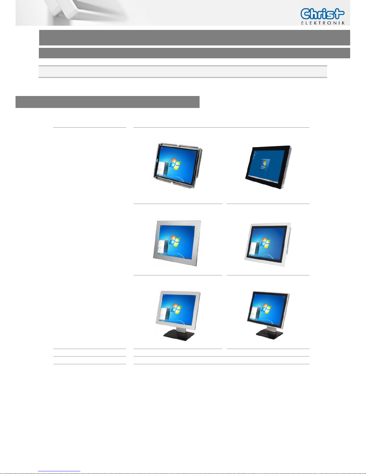
OVERVIEW
Series
Touch-it XELO
Housing
Open Frame
Open Frame glass
Front Panel
Front Panel glass
VESA
VESA glass
Touch
Foil Touch, analog resistive
Projected Capacitive Touch
Sizes (Display)
7” – 21.5”
CPU
Intel® Atom™ Single Core N270 1.6 GHz 32 Bit
AMD® G-T56N™ Dual Core 1.65 GHz 64 Bit
AMD® GX-415GA™ Quad Core 1.5 GHz 64 Bit
Intel® Core™ i5-4300U Dual Core 1.9 GHz 64 Bit
Page 6
Touch-it XELO
Operating Instructions
Copyright / © Christ-Elektronik GmbH 6 / 44 Sep. 2015, Revision 12
a member of the Christ Company Group Document No.: E461201
SYSTEM
CPU INTEL® Atom™ Single Core N270
1.6GHz 32-bit
AMD® G-T56N™ Dual Core 1.65 GHz
64-bit
Chipset INTEL® 945GSE + ICH7M
AMD A50M
Memory 2 GB DDR2
4 GB DDR3
Storage
8GB Compact Flash Card
250GB Hard Disk Drive (optional)
32 GB Solid State Drive
250 GB Hard Disk Drive(optional)
BIOS Award Plug & Play SPI BIOS – 2 MB
Flash
AMI Plug & Play
Wake on LAN
Yes
H/W Status Monitoring
Supports power supply voltages and temperature monitoring
CMOS Battery
Lithium Battery
Operating System
Windows® Embedded Standard 2009
(XP)
Linux (optional)
Microsoft® Windows® Embedded
Standard 7 Enterprise / Premium
Linux (optional)
CPU AMD® GX-415GA
Quad Core™ 1.5 GHz 64 Bit,
2 MB Cache
Intel® Core™ i5-4300U
Dual Core 1.9 GHz 64 Bit,
3 MB Cache
Chipset
Integrated in APU
Integrated in Intel® 4th Generation
Core™ i U-series
Graphic Radeon HD 8330E 500 MHz
Intel® HD Graphics 4400 200 MHz
Memory
4 GB DDR3L / 8 GB DDR3L
Storage 32 GB MLC SSD / 128 GB MLC SSD / 500 GB HDD
BIOS
AMI BIOS, Supports ACPI Function
Wake on LAN
Yes
H/W Status Monitoring
Supports Power Supply Voltages and Temperature Monitoring
CMOS Battery
Lithium Battery
Operating System Windows® Embedded Standard 7 (WS7P)
Windows® Embedded Standard 7 (WS7E)
Windows® Embedded 8 Standard
Windows® 10 IoT
Linux
POWER SUPPLY
Supply Voltage
24 VDC ± 20%
Power Consumption
See specific datasheet
Power Switch
Only VESA and VESA glass housing
Page 7
Touch-it XELO
Operating Instructions
Copyright / © Christ-Elektronik GmbH 7 / 44 Sep. 2015, Revision 12
a member of the Christ Company Group Document No.: E461201
MECHANICAL & ENVIRONMENTAL
Open Frame
Open Frame glass
Housing Front Without Frame
Without Frame
Housing
Stainless steel
Stainless steel
Cooling
Active
Active
Protection Class
IP20
IP20
Operating Temperature
0 ~ 50 °C
0 ~ 50 °C
Front Panel
Front Panel glass
Housing Front
Aluminium frame / naturally anodized
Glass, black frame
Housing
Stainless steel
Stainless steel
Cooling
Active
Active
Protection Class
IP20 (IP 65 front)
IP20 (IP 65 front)
Operating Temperature
0 ~ 50 °C
0 ~ 50 °C
VESA
VESA glass
Housing Front ---
Glass, black frame
Housing
Aluminium / anodized silver, chemi-
cally shined
Aluminium / anodized silver,
chemically shined
Cooling
Passive
Passive
Protection Class
IP20 (IP 65 front)
IP20 (IP 65 front)
Operating Temperature
0 ~ 45 °C (T56N)
0 ~ 50 °C
0 ~ 45 °C (T56N)
0 ~ 50 °C
Dimensions
See specific datasheet
Weight
See specific datasheet
Storage Temperature
-10 ~ 70 °C
Humidity
5 ~ 80% (non condensing)
Certification CE, EN55022, EN55024, DIN EN ISO 9001
CAUTION!
Never cover the Touch-it XELO completely or build it in a small closed
and unvented housing.
Page 8
Touch-it XELO
Operating Instructions
Copyright / © Christ-Elektronik GmbH 8 / 44 Sep. 2015, Revision 12
a member of the Christ Company Group Document No.: E461201
2 Commissioning
2.1 Mounting
2.1.1 Touch-it XELO Open Frame / Open Frame glass
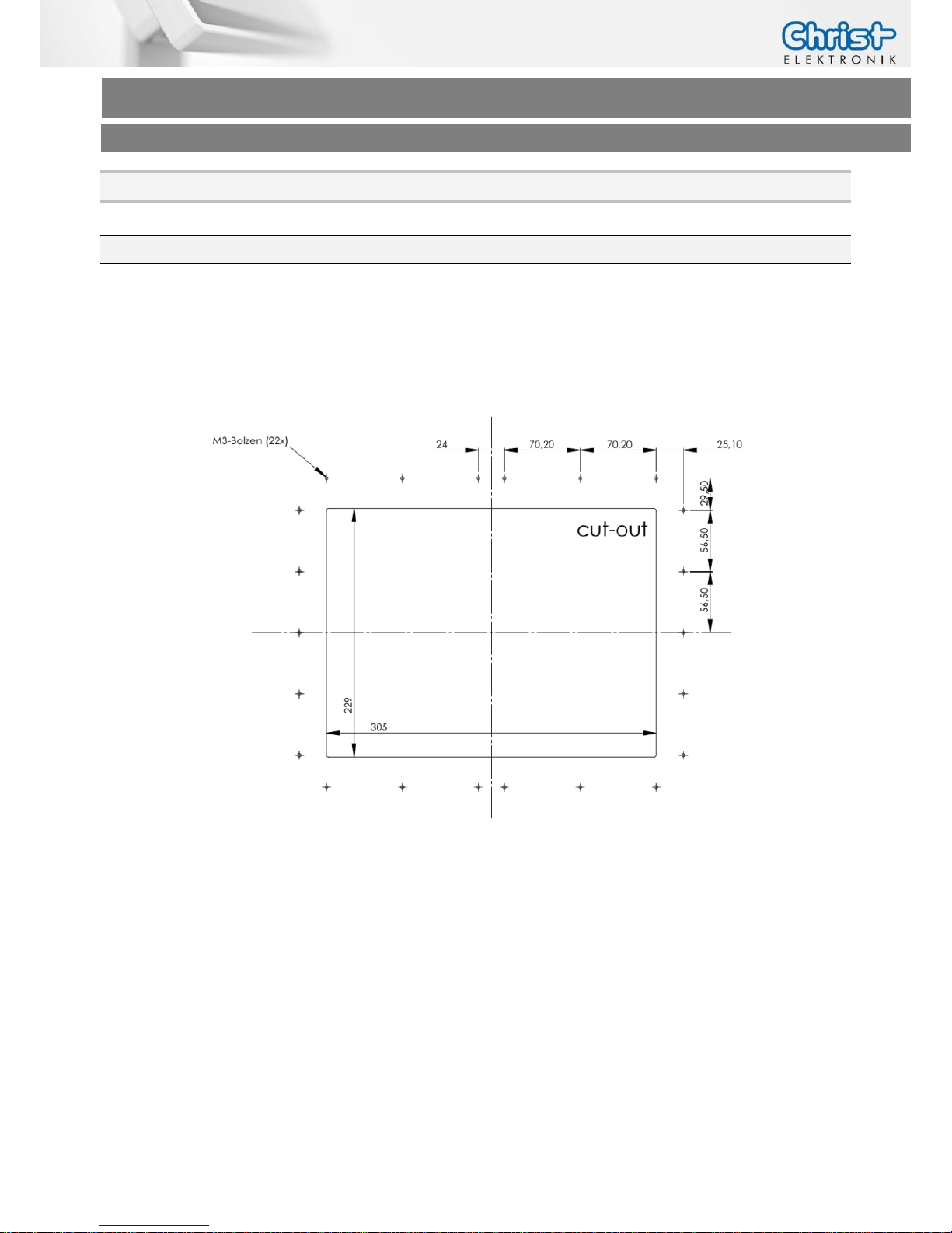
The variant Touch-it XELO Open Frame is designed for customer specific mounting.
Each Open Frame Panel has its own cut-out drawing.
For example:
For the appropriated drawing see the specific data sheet.
Page 9
Touch-it XELO
Operating Instructions
Copyright / © Christ-Elektronik GmbH 9 / 44 Sep. 2015, Revision 12
a member of the Christ Company Group Document No.: E461201
2.1.2 Touch-it XELO Front Panel / Front Panel glass
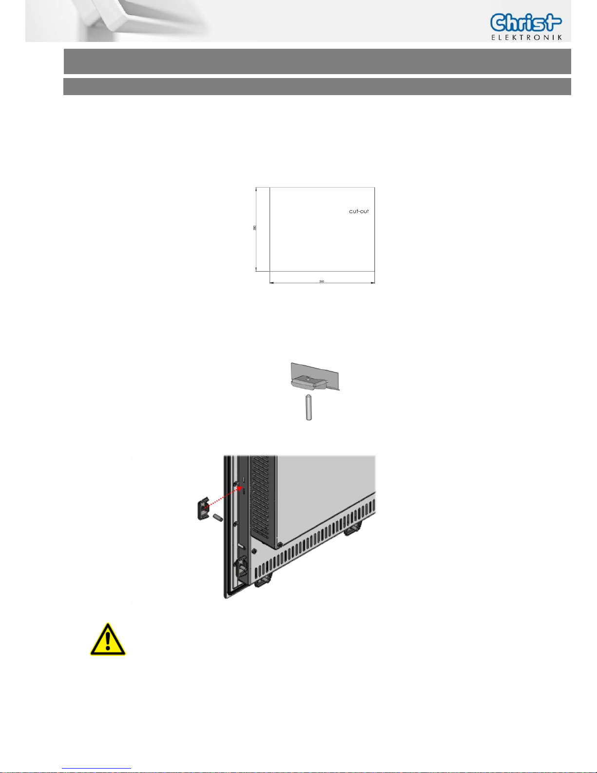
The variant Touch-it XELO Front Panel is designed for front mounting.
Each Front Panel has its own cut-out drawing.
For the appropriated drawing see the specific data sheet.
To clamp the Front Panel into the cut-out you can use the attached fasting clamps.
Fasting Clamp
CAUTION!
For the best installation result the use of all provided fasting
clamps is highly recommended. Depending on individual installation circumstances a new IP rating may be considered.
Page 10
Touch-it XELO
Operating Instructions
Copyright / © Christ-Elektronik GmbH 10 / 44 Sep. 2015, Revision 12
a member of the Christ Company Group Document No.: E461201
2.1.3 Touch-it XELO VESA / VESA glass
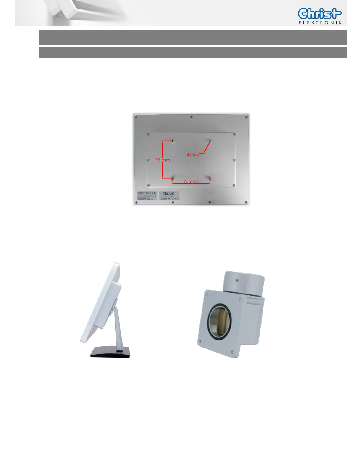
The variant Touch-it CE VESA is designed for VESA MIS-D, 75, C mounts.
Some panels can also be mounted with VESA MIS-D, 100, C.
Suitable mounting variants are:
VESA Desk Stand Arm Mounting System VESA-SA75
Page 11
Touch-it XELO
Operating Instructions
Copyright / © Christ-Elektronik GmbH 11 / 44 Sep. 2015, Revision 12
a member of the Christ Company Group Document No.: E461201
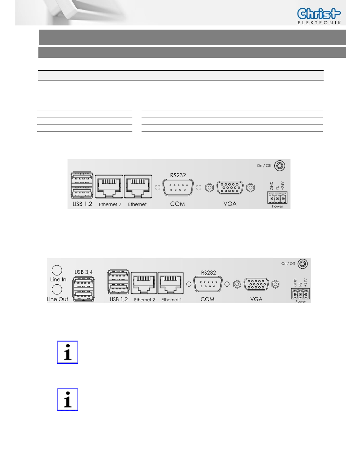
2.2 Interfaces Connector Side (CPU N270 / T56N)
USB
2 x USB Host (Type A)
4 x USB Host (Type A) (optional)
Ethernet
2 x 1 GB Ethernet
Communication
1 x RS-232
Video
1 x VGA
Audio
Line In, Line Out (optional)
Power Connector
Phoenix
Connector side Touch-it XELO (CPU N270 / T56N)
Connector side Touch-it XELO extended (CPU N270 / T56N)
On/Off is only included with housing VESA and VESA glass.
All interfaces are described in the chapter Interfaces.
Page 12
Touch-it XELO
Operating Instructions
Copyright / © Christ-Elektronik GmbH 12 / 44 Sep. 2015, Revision 12
a member of the Christ Company Group Document No.: E461201
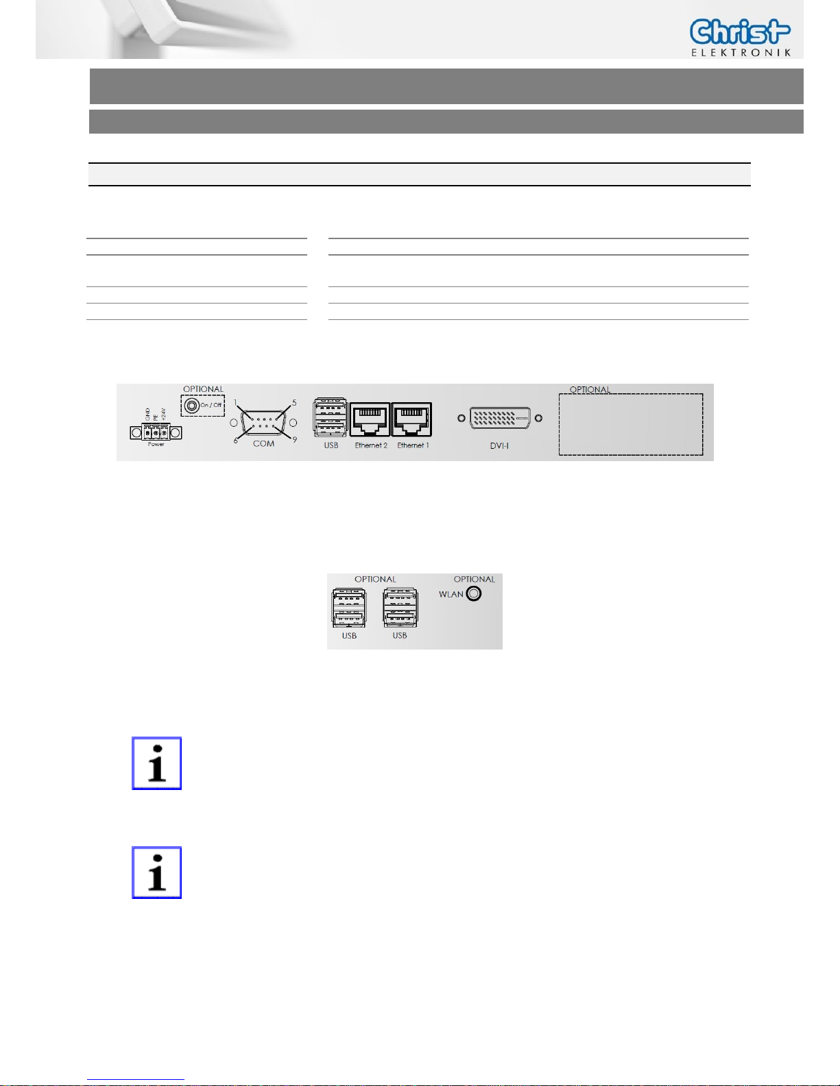
2.3 Interfaces Connector Side (CPU GX-415GA / i5-5300U)
USB
2 x USB 3.0 Host (Type A)
2 x USB 2.0 Host (Type A) (optional)
Ethernet
2 x 1 GB Ethernet
Communication
1 x RS-232 or RS-422 or RS-485
(Can be set via BIOS)
Video
1 x DVI
WLAN
1 x 802.11 ac/a/b/g/n 2.4 GHz, 5 GHz, (optional)
Power Connector
Phoenix
Connector side Touch-it XELO (CPU GX-415GA / i5-5300U)
Connector side Optional (CPU GX-415GA / i5-5300U )
On/Off is only included with housing VESA and VESA glass.
All interfaces are described in the chapter Interfaces.
Page 13
Touch-it XELO
Operating Instructions
Copyright / © Christ-Elektronik GmbH 13 / 44 Sep. 2015, Revision 12
a member of the Christ Company Group Document No.: E461201
3 Software
3.1 Award BIOS Setup (CPU N270)
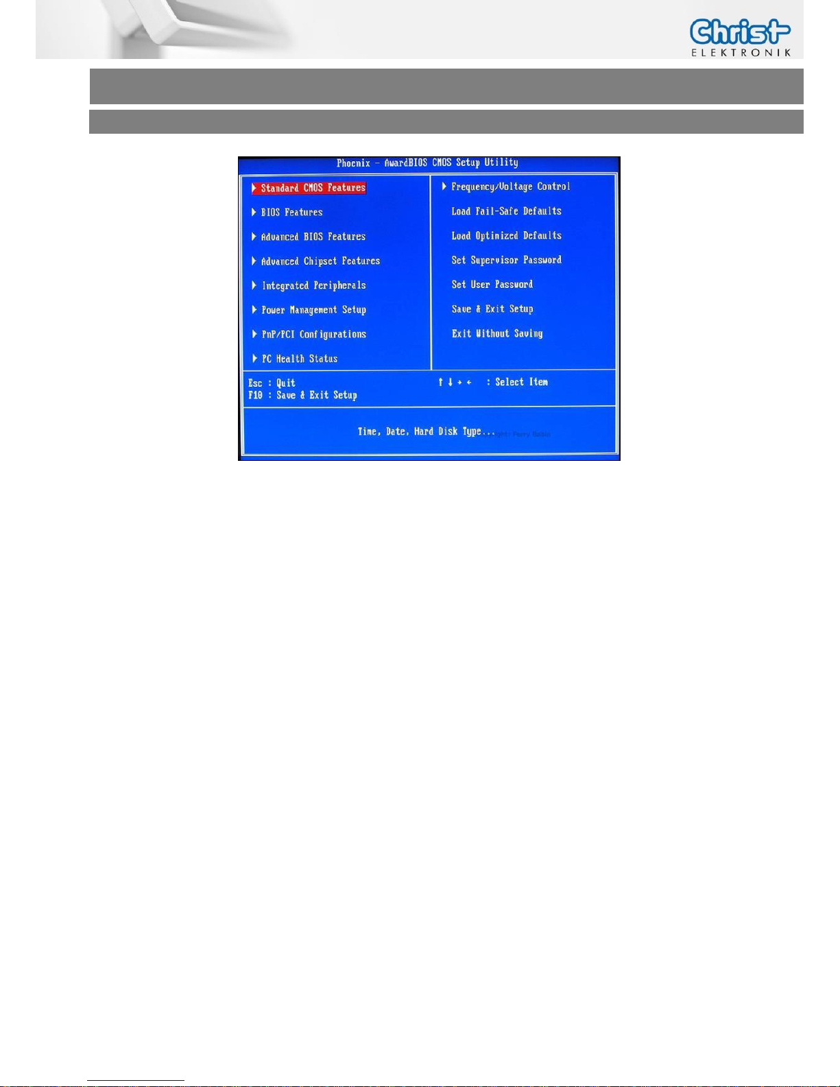
Awards BIOS ROM has a built-in Setup program that allows users to modify the basic system
configuration. This type of information is stored in battery-backed CMOS RAM so that it retains
the Setup information when the power is turned off.
Entering Setup
Power on the computer and press “Del” immediately. This will allow you to enter Setup.
Standard CMOS Features
Basic system configuration. (Date, time, IDE, etc.)
Advanced BIOS Features
Set the advanced features available on your system.
Advanced Chipset Features
Change the values in the chipset registers and optimize your system performance.
Integrated Peripherals
Settings for integrated peripherals.
(Primary slave, secondary slave, keyboard, mouse etc.)
Power Management Setup
Settings for power management.
(HDD power down, power on by ring, KB wake up, etc.)
Page 14
Touch-it XELO
Operating Instructions
Copyright / © Christ-Elektronik GmbH 14 / 44 Sep. 2015, Revision 12
a member of the Christ Company Group Document No.: E461201
3.1.1 Changing Display Resolution
In the BIOS Setup mode choose the [Advanced Chipset Features]
Menu and set the Internal LVDS
Save this configuration by pressing “F10” and afterwards “Y”.
3.1.2 Changing Boot Priority
In order to boot from a USB Drive the following settings must be done.
In the BIOS Setup mode choose the [Advanced BIOS Features] Menu and set the Hard Disk Boot
Priority in such a way that the USB-HDD0 Device is first in the boot list.
This can be done using the Page-Up/Down Keys.
Save this configuration by pressing “F10” and afterwards “Y”.
Page 15

Touch-it XELO
Operating Instructions
Copyright / © Christ-Elektronik GmbH 15 / 44 Sep. 2015, Revision 12
a member of the Christ Company Group Document No.: E461201
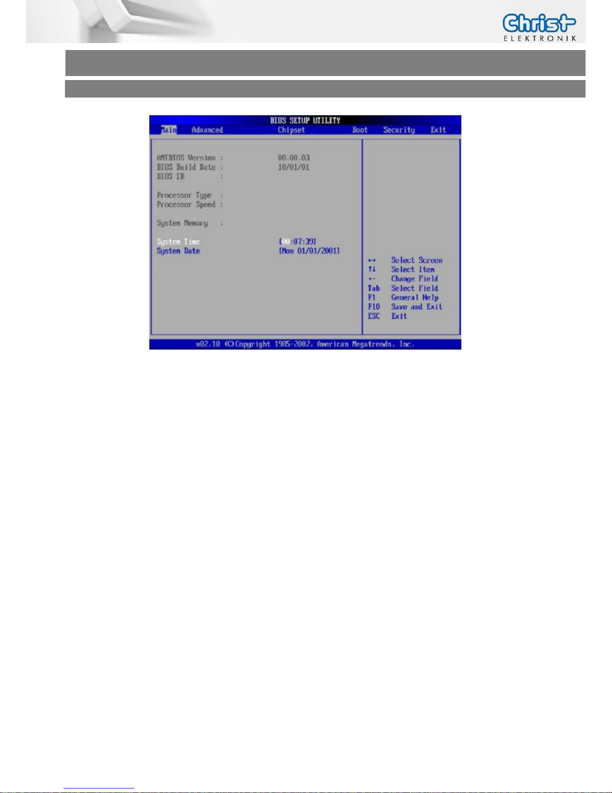
3.2 American Megatrends, Inc. (AMI) BIOS Setup (CPU T56N)
AMI BIOS ROM has a built-in Setup program that allows users to modify the basic system configuration. This type of information is stored in battery-backed CMOS RAM so that it retains the
Setup information when the power is turned off.
Entering Setup
Power on the computer and press “Del” or “F2” immediately. This will allow you to enter Setup.
Main
Set the date.
Advanced
Advanced BIOS Features Setup including TPM, ACPI, etc.
Chipset
Host bridge parameters.
Boot
Boot option.
Security
Set setup administrator password.
Save&Exit
Exit system setup after saving the changes.
Page 16
Touch-it XELO
Operating Instructions
Copyright / © Christ-Elektronik GmbH 16 / 44 Sep. 2015, Revision 12
a member of the Christ Company Group Document No.: E461201
3.2.1 Changing Display Resolution
In the BIOS Setup mode choose the Chipset Menu select North Bridge and then
Graphics Configuration.
Set the LVDS2 Panel Type
Save this configuration by pressing “F4” and selecting “Yes” afterwards.
3.2.2 Changing Boot Priority
In order to boot from a USB Drive the following settings must be done.
In the BIOS Setup mode choose the Boot Menu and select Hard Drive BBS Priorities.
Set the Boot Option #1 in such a way that the USB Device is first position in the boot list, by
pressing “Enter” and select the USB Device using the Page-Up/Down Keys.
Save this configuration by pressing “F4” and selecting “Yes” afterwards.
Page 17
Touch-it XELO
Operating Instructions
Copyright / © Christ-Elektronik GmbH 17 / 44 Sep. 2015, Revision 12
a member of the Christ Company Group Document No.: E461201
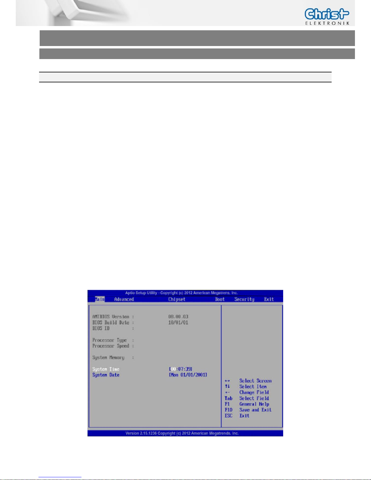
3.3 American Megatrends, Inc. (AMI) BIOS (CPU GX-415GA / i5-5300U)
AMI BIOS ROM has a built-in Setup program that allows users to modify the basic system configuration. This type of information is stored in battery-backed CMOS RAM so that it retains the
Setup information when the power is turned off.
Entering Setup
Power on the computer and press “Del” or “F2” immediately. This will allow you to enter Setup.
Main
Set the date.
Advanced
Advanced BIOS Features Setup including COM setting, ACPI, etc.
Chipset
Host bridge parameters.
Boot
Boot option.
Security
Set setup administrator password.
Save&Exit
Exit system setup after saving the changes.
Page 18

Touch-it XELO
Operating Instructions
Copyright / © Christ-Elektronik GmbH 18 / 44 Sep. 2015, Revision 12
a member of the Christ Company Group Document No.: E461201
3.3.1 Changing Display Resolution (CPU GX-415GA)
To change the display resolution the following settings must be done.
In the BIOS Setup mode choose the Chipset Menu select LVDS Panel Config Select.
Set the LVDS Panel Config Select.
Save this configuration by pressing “F4” and selecting “Yes” afterwards.
3.3.2 Changing Display Resolution (CPU i5-4300U)
To change the display resolution the following settings must be done.
In the BIOS Setup mode choose the Chipset Menu select
System Agent (SA) Configuration -> Graphics Configuration -> LCD Control.
Set the LCD Panel Type.
Save this configuration by pressing “F4” and selecting “Yes” afterwards.
3.3.3 Changing Boot Priority
In order to boot from a USB Drive the following settings must be done.
In the BIOS Setup mode choose the Boot Menu and select Hard Drive BBS Priorities.
Set the Boot Option #1 to the USB Device, by pressing “Enter” and select the USB Device.
Save this configuration by pressing “F4” and selecting “Yes” afterwards.
Page 19

Touch-it XELO
Operating Instructions
Copyright / © Christ-Elektronik GmbH 19 / 44 Sep. 2015, Revision 12
a member of the Christ Company Group Document No.: E461201
3.3.4 Changing COM Port (CPU GX-415GA)
To change the COM Port to RS-422 / RS-485 / RS-232 the following settings must be done.
In the BIOS Setup mode choose the Advanced Menu select F81866 Super IO Configuration.
Select Serial Port0 Configuration and be sure that Serial Port [Enabled] is set.
Set the Mode Select to your favourite interface.
3.3.1 Changing COM Port (CPU i5-4300U)
To change the COM Port to RS-422 / RS-485 / RS-232 the following settings must be done.
In the BIOS Setup mode choose the Advanced Menu select NCT6102D Super IO Configura-
tion.
Select Serial Port0 Configuration and be sure that Serial Port [Enabled] is set.
Set the Mode Select to your favourite interface.
Page 20
Touch-it XELO
Operating Instructions
Copyright / © Christ-Elektronik GmbH 20 / 44 Sep. 2015, Revision 12
a member of the Christ Company Group Document No.: E461201
3.4 Redo Backup and Recovery
3.4.1 Generate bootable Redo Backup and Recovery USB stick
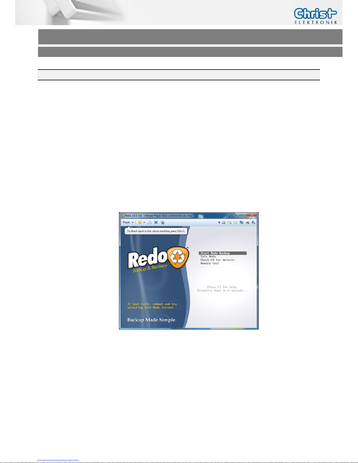
There are two ways to create a Redo USB Drive with VMWare or directly booting a LiveCD.
VMWare:
Christ-Elektronik GmbH created a complete VMWare Virtual Machine running Redo
V1.0.3
Download and Install VMWare Player 5.0 or higher
Download the VMWare Image (Redo 1.0.3.zip) from our SFTP in \out\Redo Images\ (See
chapter 3.7
Page 21
Touch-it XELO
Operating Instructions
Copyright / © Christ-Elektronik GmbH 21 / 44 Sep. 2015, Revision 12
a member of the Christ Company Group Document No.: E461201
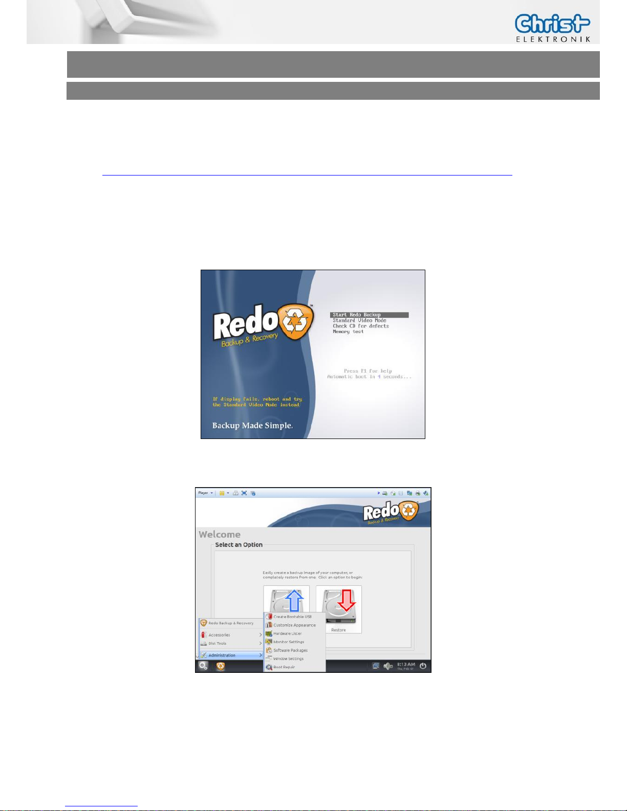
LiveCD:
Download the Redo Backup live CD Image version 1.0.3 (don´t use version 1.0.4 or newer)
http://sourceforge.net/projects/redobackup/files/redobackup-livecd-1.0.3.iso/download
Burn the image to a CD
You'll need to burn the ISO disc image using a CD burning program.
Change the Bios Settings of your PC to boot from the CD-ROM Drive.
Start Redo Backup from CD and wait a few minutes.
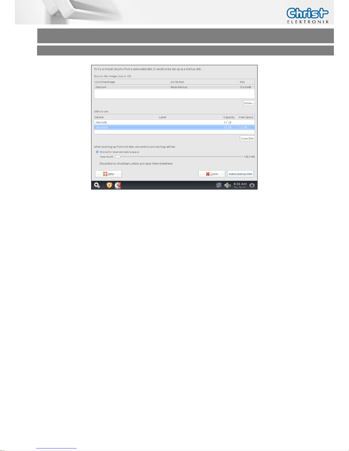
Plug in a 4GB or greater USB Stick and choose Administration -> Create Bootable USB.
Choose the Disk to use, press Make Startup Disk and wait a few minutes.
Page 22
Touch-it XELO
Operating Instructions
Copyright / © Christ-Elektronik GmbH 22 / 44 Sep. 2015, Revision 12
a member of the Christ Company Group Document No.: E461201
3.4.2 Restoring an Image with Redo Backup and Recovery
If you have a Touch-it XELO Image Backup, copy the folder and files to the root directory of the
Redo USB Drive. (See Chapter Software->Redo Backup and Recovery)
Plug in an USB Keyboard and the Redo USB Drive directly to the Touch-it XELO port
without using a USB Hub.
Enter the BIOS Setup and set the following BIOS Settings:
(See Chapter Software -> Award BIOS Setup or Software -> American Megatrends BIOS
Setup)
I. Set the Hard Disk Boot Priority to your USB connected Drive
II. Set the internal LVDS to 1024x768 (18bit)
III. Save the changes and reboot your System
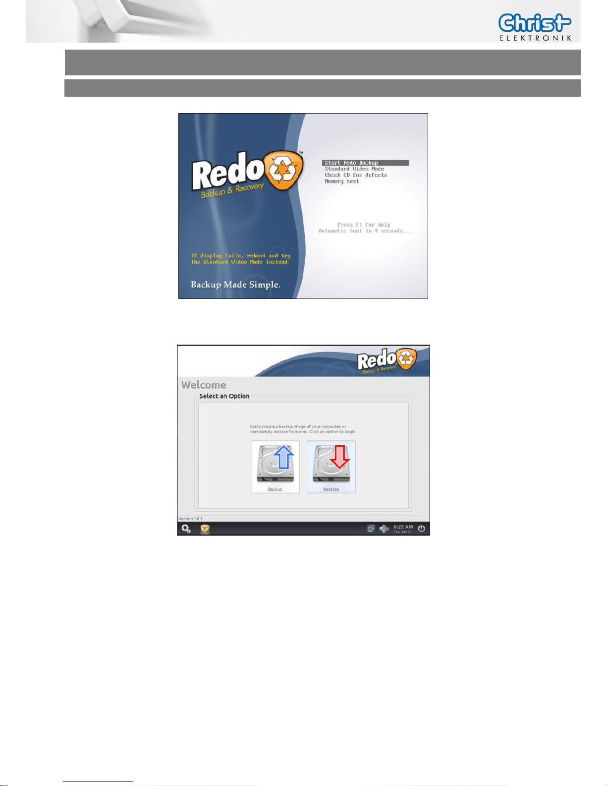
Start Redo Backup and wait a few minutes (If no display appears, connect an external Monitor to
the VGA Port.
Page 23
Touch-it XELO
Operating Instructions
Copyright / © Christ-Elektronik GmbH 23 / 44 Sep. 2015, Revision 12
a member of the Christ Company Group Document No.: E461201
Choose the Menu Restore.
Step 1: Select the Source Drive where Redo Backup is on, normally it should be Drive 2/3
and click next.
Step 2: Select the Backup Image Directory, click Open and then Next.
Step 3: Select the Destination Drive normally it should be Drive 1, click Next and Yes to
overwrite data on this drive.
After 5-10 minutes depending on the image size the restoring should be complete.
Page 24
Touch-it XELO
Operating Instructions
Copyright / © Christ-Elektronik GmbH 24 / 44 Sep. 2015, Revision 12
a member of the Christ Company Group Document No.: E461201
3.5 Generate an USB drive for BIOS update
3.5.1 List of needed files
MS-DOS Files for creating the bootable USB drive:
COMMAND.COM
IO.SYS
MSDOS.SYS
USB Stick Format Tool:
HPUSBFW_v2.2.3.exe
AMI BIOS Update Files:
V00C9MXX.rom
go.bat
AFUDOS.exe
INFORMATION!
The needed files you can get from Christ-Elektronik.
3.5.2 Format the USB Stick and make it bootable
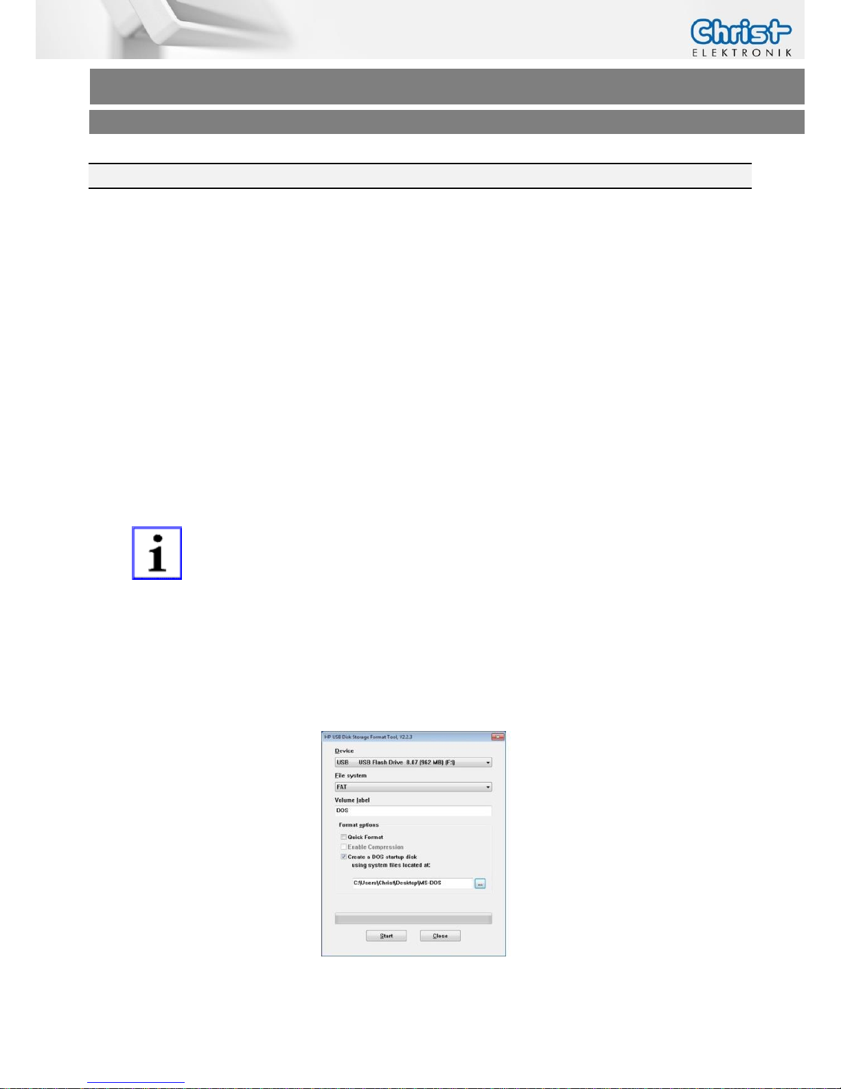
Start the “HP USB Disk Storage Format Tool” by running the File “HPUSBFW_v2.2.3.exe”
on the Development / Desktop PC as Administrator.
Configure the Tool as seen on the picture below
Page 25
Touch-it XELO
Operating Instructions
Copyright / © Christ-Elektronik GmbH 25 / 44 Sep. 2015, Revision 12
a member of the Christ Company Group Document No.: E461201
3.5.3 Copy the BIOS Update Files
Copy the BIOS Update Files to the recently created USB Drive
V00C9MXX.rom,
go.bat and AFUDOS.exe
3.5.4 Configure the BIOS settings
Plug in a USB Keyboard and the bootable USB Drive to the Touch-It XELO
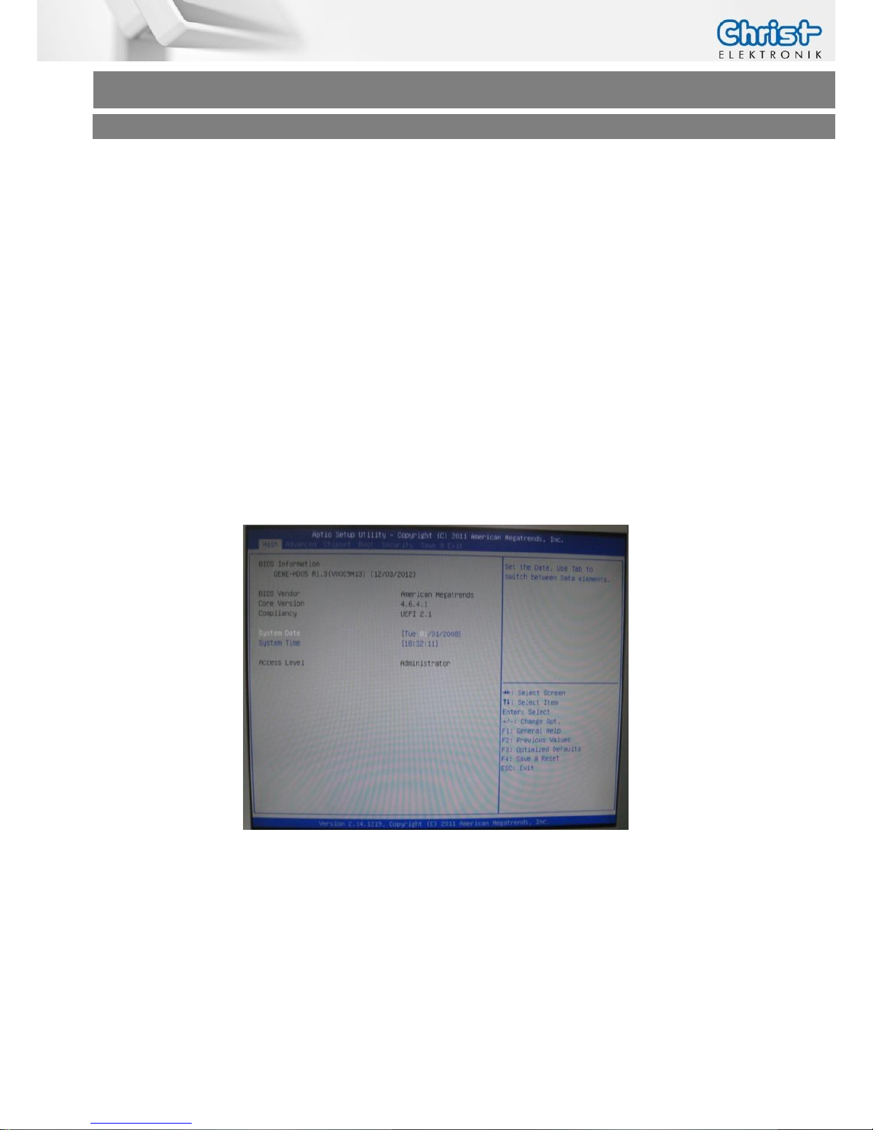
Enter the BIOS Setup by pressing “Delete”
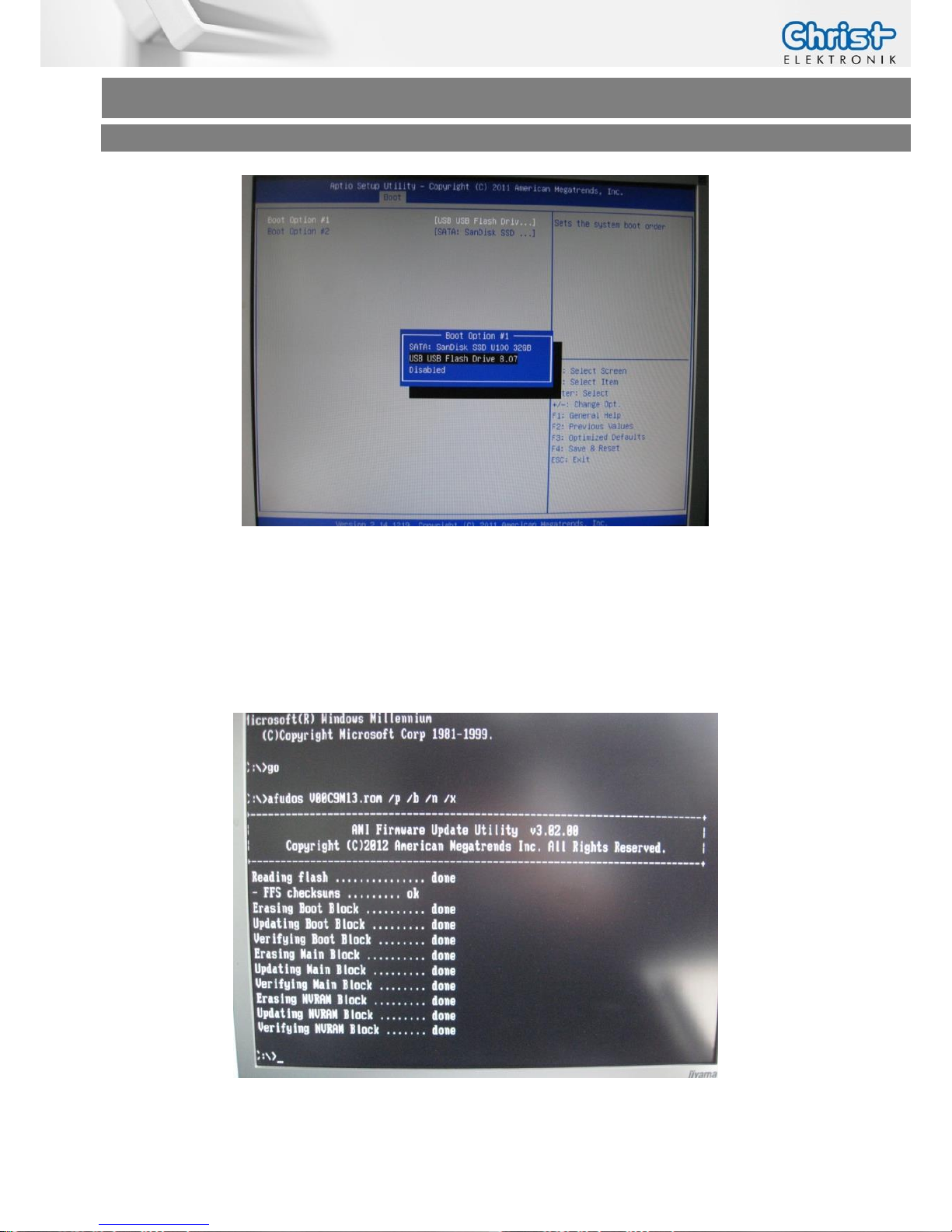
Following screen will appear on the monitor/display
Enter the Bios menu and set the Hard Disk Boot Priority to your USB connected Drive.
(See Chapter Software –> Award BIOS Setup or Software -> American Megatrends BIOS Setup)
Page 26
Touch-it XELO
Operating Instructions
Copyright / © Christ-Elektronik GmbH 26 / 44 Sep. 2015, Revision 12
a member of the Christ Company Group Document No.: E461201
Press “F4” + “Enter” and the Touch Panel will reboot.
3.5.5 Update the BIOS
Run go.bat in the MS-DOS command console, wait until done and reboot.
Page 27
Touch-it XELO
Operating Instructions
Copyright / © Christ-Elektronik GmbH 27 / 44 Sep. 2015, Revision 12
a member of the Christ Company Group Document No.: E461201
3.6 Enhanced Write Filter EWF
Windows XP, Windows 7 or Windows 8 embedded operating systems are delivered by default
with EWF protection from Christ-Elektronik. This so called Enhanced Write Filter prevents write
accesses to a protected drive (SSD/HDD) and therefore unintentional system changes (blue
screens, viruses, user errors, etc.).
- The “C” system partition is EWF protected by default
- The “D” data partition is not EWF protected by default
- Advantage: clean, fast system without viruses and blue screens
3.6.1 Enable or Disable the EWF Filter
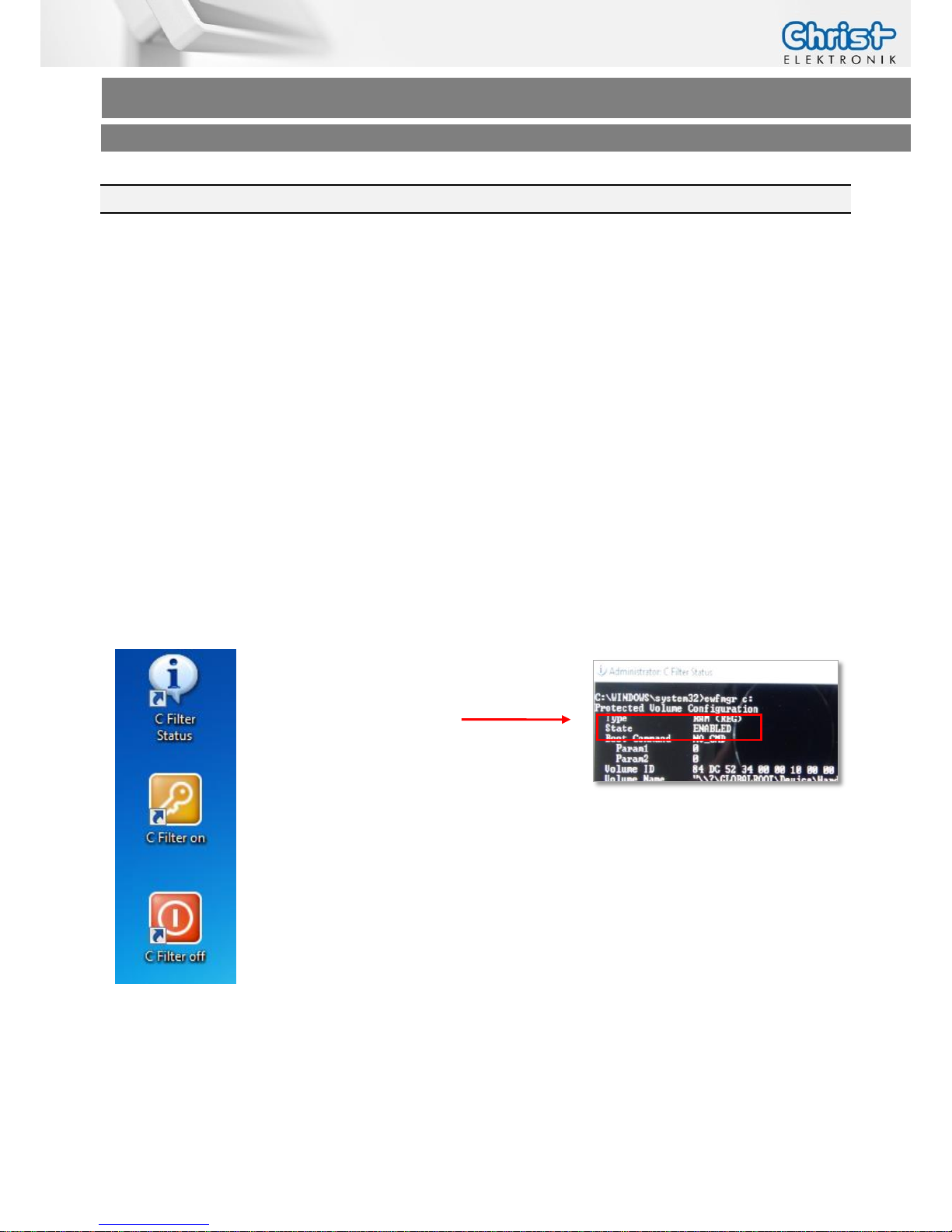
On the desktop of your Touch-it Panel PC you will find three icons for the Enhanced Write Filter
control.
“C Filter Status”:
View information about the EWF drive
Delivery state: Enabled
“C Filter On“:
Write protection for partition C:
Turn on, effective only after restarting the touch panel
“C Filter Off”:
Write protection for partition C:
Turn off, changes are immediately accepted
Page 28
Touch-it XELO
Operating Instructions
Copyright / © Christ-Elektronik GmbH 28 / 44 Sep. 2015, Revision 12
a member of the Christ Company Group Document No.: E461201
3.7 SFTP Server
Christ-Elektronik ist equipped with a SFTP server.
SFTP is tunneled with the SSH Protocol (Port 22). A special Client is necessary to get access.
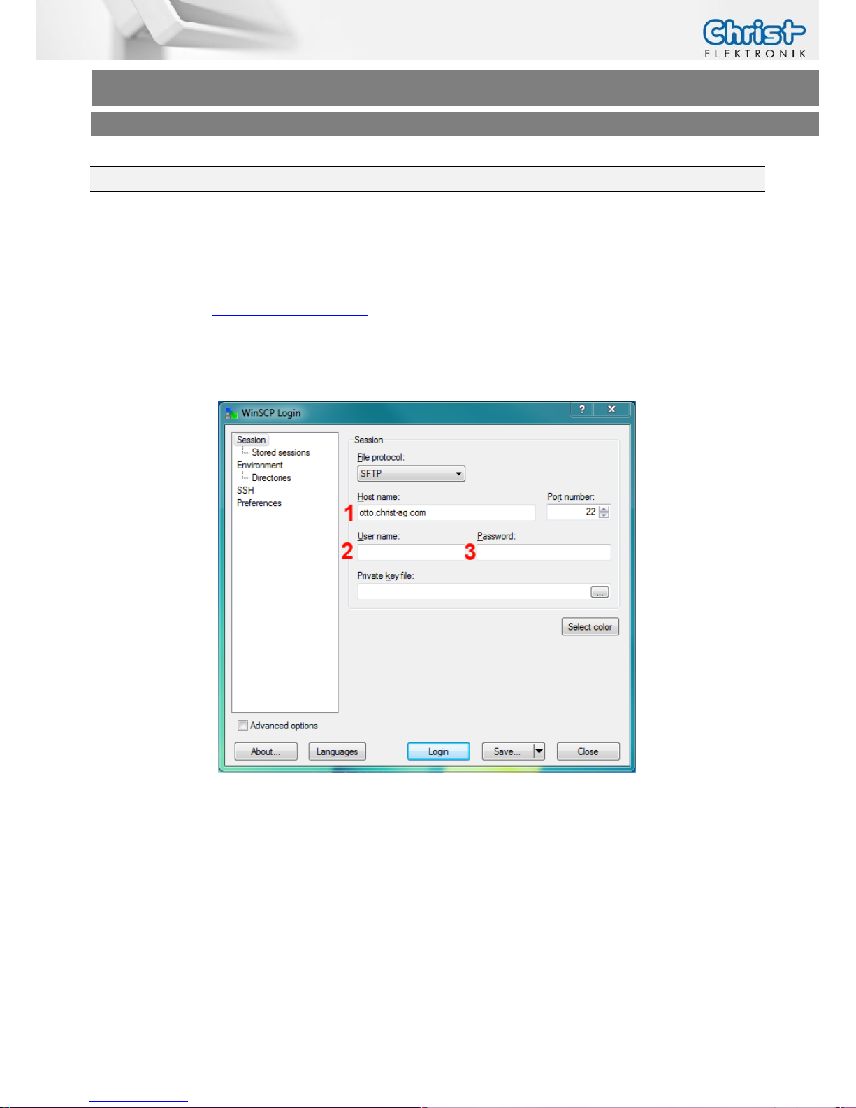
Use the WinSCP (http://www.winscp.net) or something similar.
Download, install and start the WinSCP Client.
(1) Servername („otto.christ-ag.com“)
(2) Username (get it from Christ-Elektronik)
(3) Password (get it from Christ-Elektronik)
(4) Click on “Login”
Page 29
Touch-it XELO
Operating Instructions
Copyright / © Christ-Elektronik GmbH 29 / 44 Sep. 2015, Revision 12
a member of the Christ Company Group Document No.: E461201
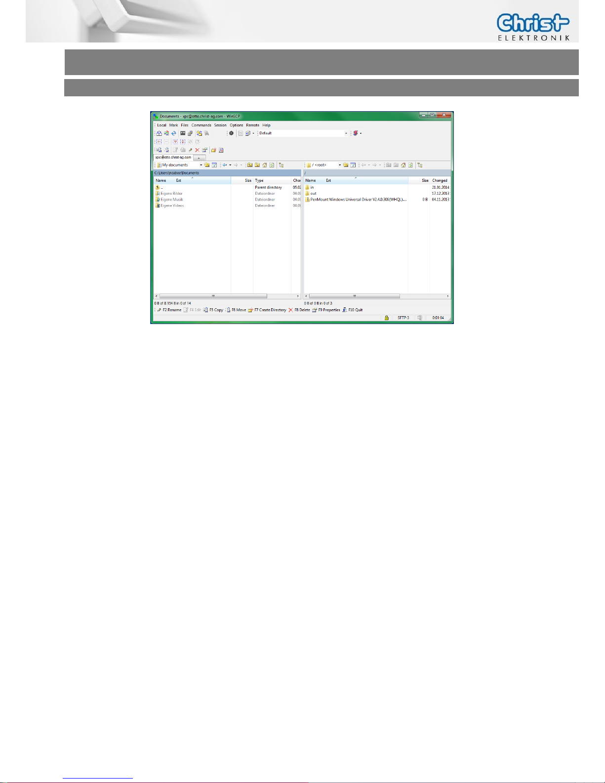
The left window show you the local drives.
The right window show you the SFTP drives.
Per Drag & Drop you can copy the files.
Structure:
“in” – Files from extern to Christ-Elektronik GmbH
->write acces for both sides.
“out” – Files from Christ-Elektronik GmbH to extern
->write acces for Christ-Elektronik only
Page 30
Touch-it XELO
Operating Instructions
Copyright / © Christ-Elektronik GmbH 30 / 44 Sep. 2015, Revision 12
a member of the Christ Company Group Document No.: E461201
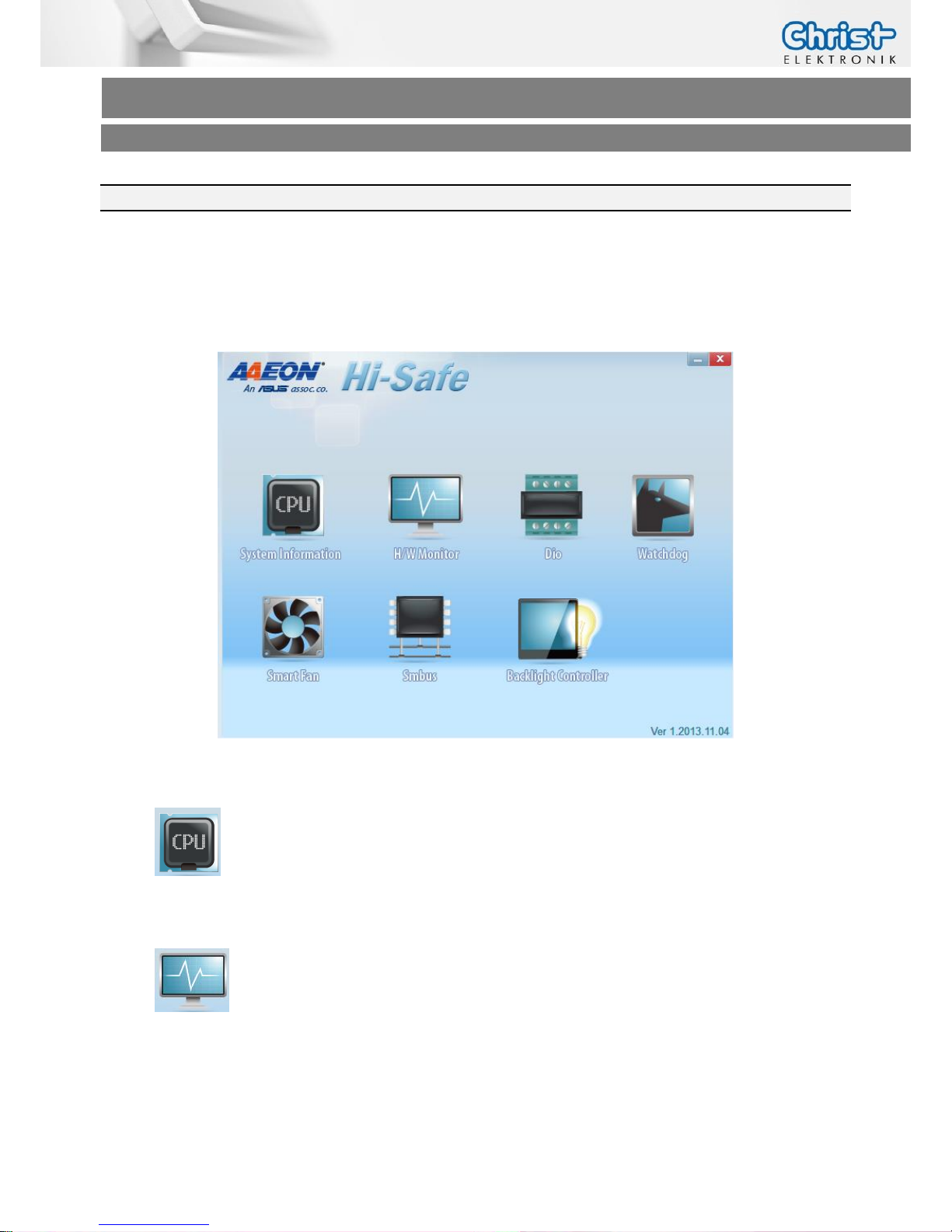
3.8 Hi-Safe (CPU N270 / T56N)
The tool Hi-Safe provides features over the current system.
You can get the installation file from Christ-Elektronik.
1. System Information: Show the information of CPU, VGA and RAM.
2. H/W Monitor: Show the information in the Super IO. Get the speed of fan,
temperature and voltage.
Page 31
Touch-it XELO
Operating Instructions
Copyright / © Christ-Elektronik GmbH 31 / 44 Sep. 2015, Revision 12
a member of the Christ Company Group Document No.: E461201
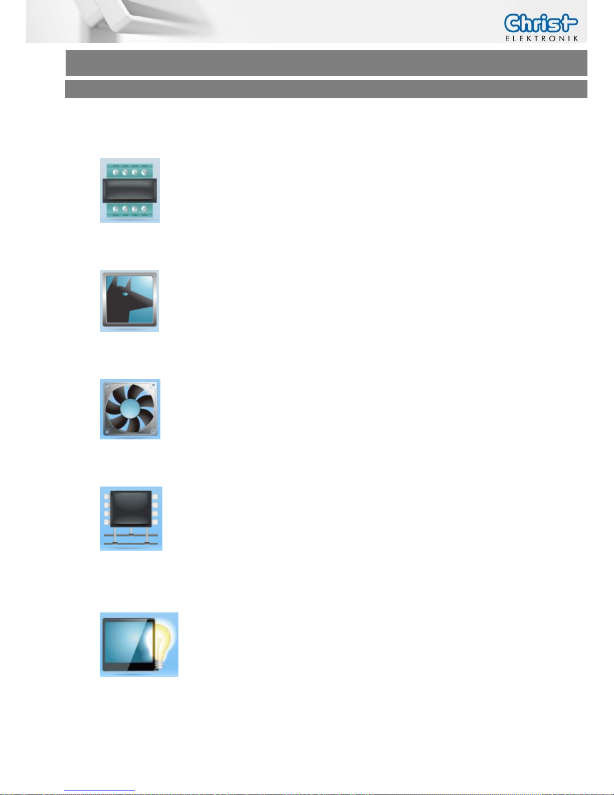
3. Dio: Through the application, obtain the Digital IO information. It can be set for
the pin’s direction (input or output) and accessed for set/read pin’s data (low or
high), upon the direction of pin configured. (The standard Touch-it XELO has no DIO´s)
4. Watchdog: Set the countdown time of system reboot when timeout happens.
The time mode is the second or minute. The count value is from 0 to 255.
5. Smart Fan: Show the Speed of fan and associated Temperature. It also can control
the fan speed corresponding to temperature. (only by Touch-it XELO with fan possible)
6. Smbus: Get data of device connected to Smbus (I2C). It can automatically detect
the base address of Smbus.
7. Backlight Controller: It has two modes. One is Inverter mode through Smbus, and the
other is PWM mode. It can control the brightness of LVDS interface LCD panel.
(Function is not available at all panels)
Page 32
Touch-it XELO
Operating Instructions
Copyright / © Christ-Elektronik GmbH 32 / 44 Sep. 2015, Revision 12
a member of the Christ Company Group Document No.: E461201
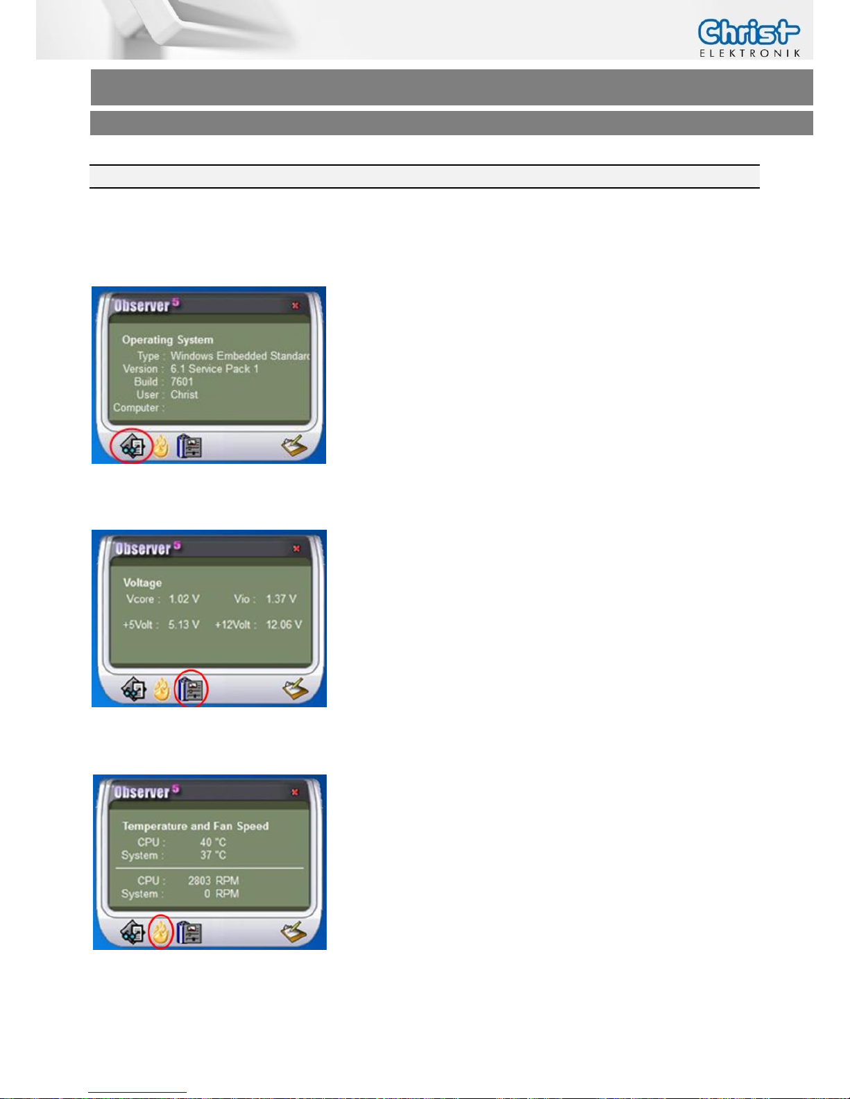
3.9 Observer (CPU GX-415GA / i5-5300U)
The tool Observer provides features over the current system.
1. Operating System
Shows information about the current Operating System.
2. Voltage
Shows information about the current system voltages.
3. Temperature and Fan Speed
Shows information about the temperature and fan speed.
Page 33
Touch-it XELO
Operating Instructions
Copyright / © Christ-Elektronik GmbH 33 / 44 Sep. 2015, Revision 12
a member of the Christ Company Group Document No.: E461201
4 Touch Calibration
4.1 Projected Capacitive Touch
There is no need to calibrate the projected capacitive touch.
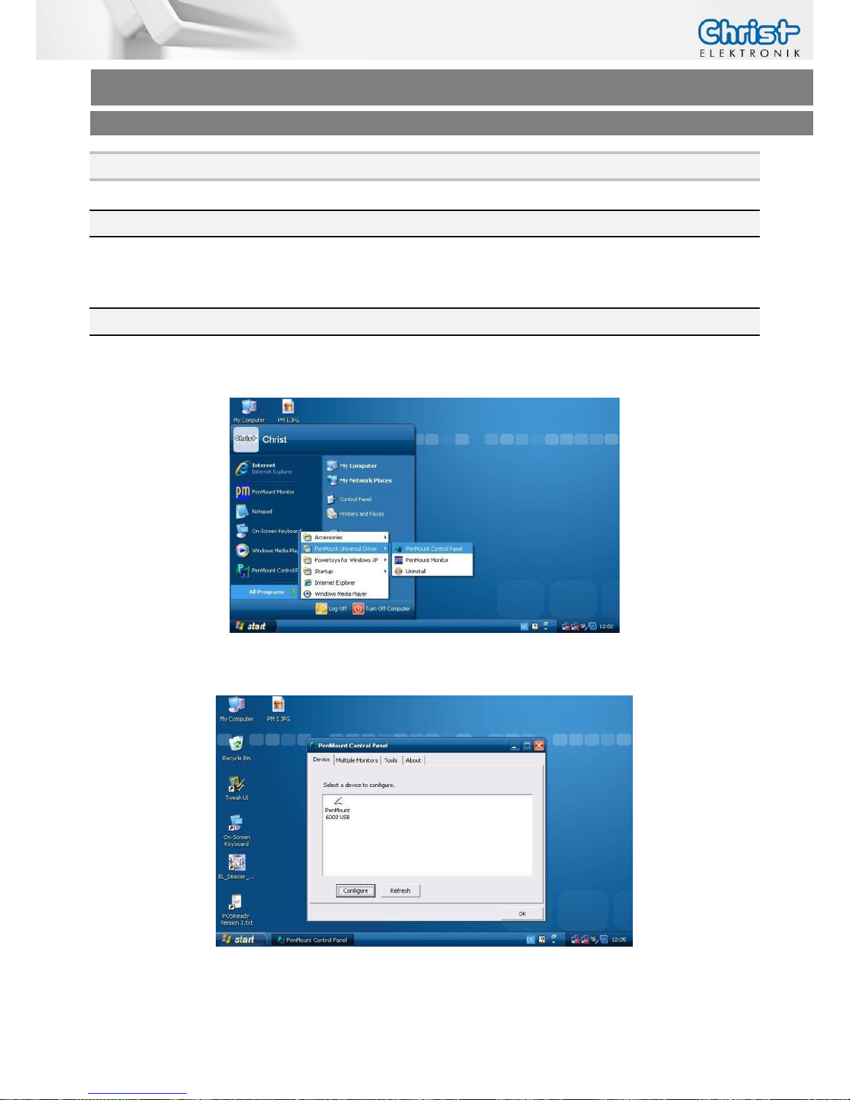
4.2 Foil-/Glass-Touch analog resistive 7” to 15”
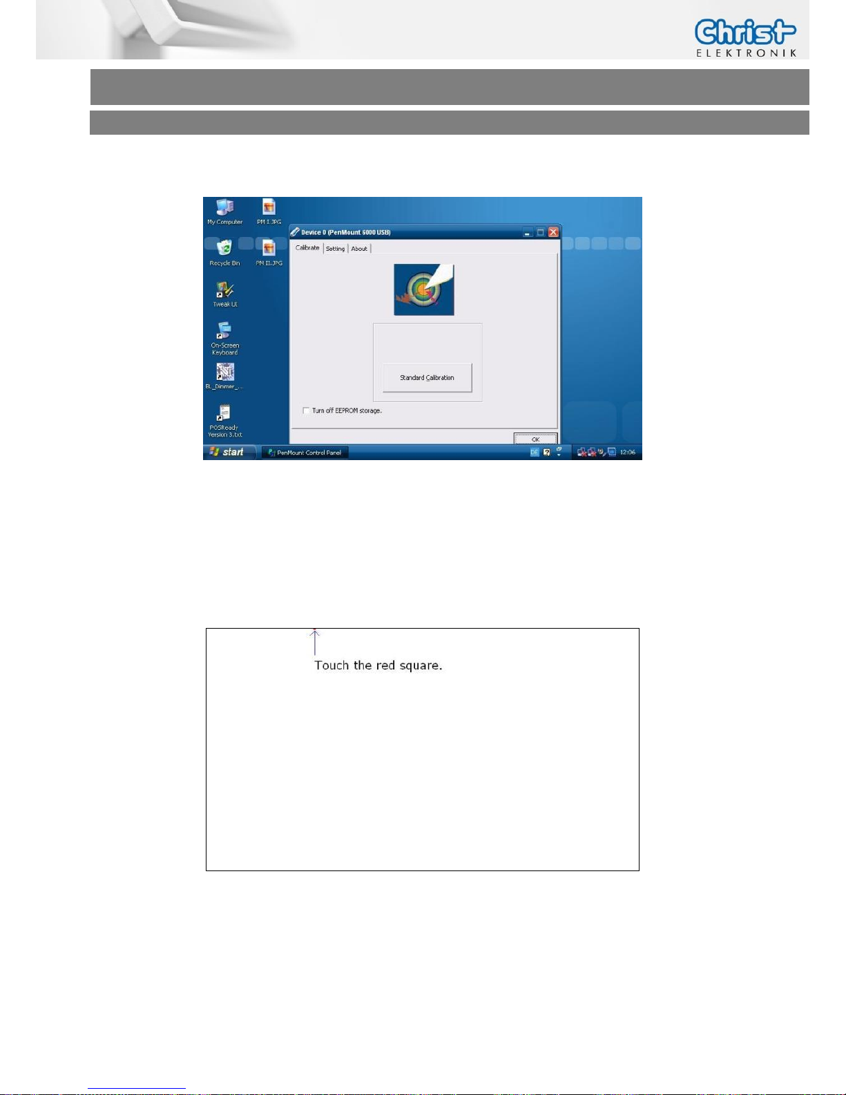
1. Click on [Start] [All Programs] [Pen Mount Universal Driver] [Pen Mount Control Panel]
2. Click on [Pen Mount 6000 USB]
Page 34
Touch-it XELO
Operating Instructions
Copyright / © Christ-Elektronik GmbH 34 / 44 Sep. 2015, Revision 12
a member of the Christ Company Group Document No.: E461201
3. Click on [Standard Calibration]
4. Pressing the [Standard Calibration] button on the main window activates the calibration
screen to carry out calibration of the Touch-it Panel PC.
Briefly touch the center of the red square splayed on the screen in order as they appear.
Once calibration is carried out, the calibrated value is saved. Since the calibrated value is
read from the setting file at the time of the next start up, there is no need to carry out
calibration again.
Page 35
Touch-it XELO
Operating Instructions
Copyright / © Christ-Elektronik GmbH 35 / 44 Sep. 2015, Revision 12
a member of the Christ Company Group Document No.: E461201
5 Interfaces
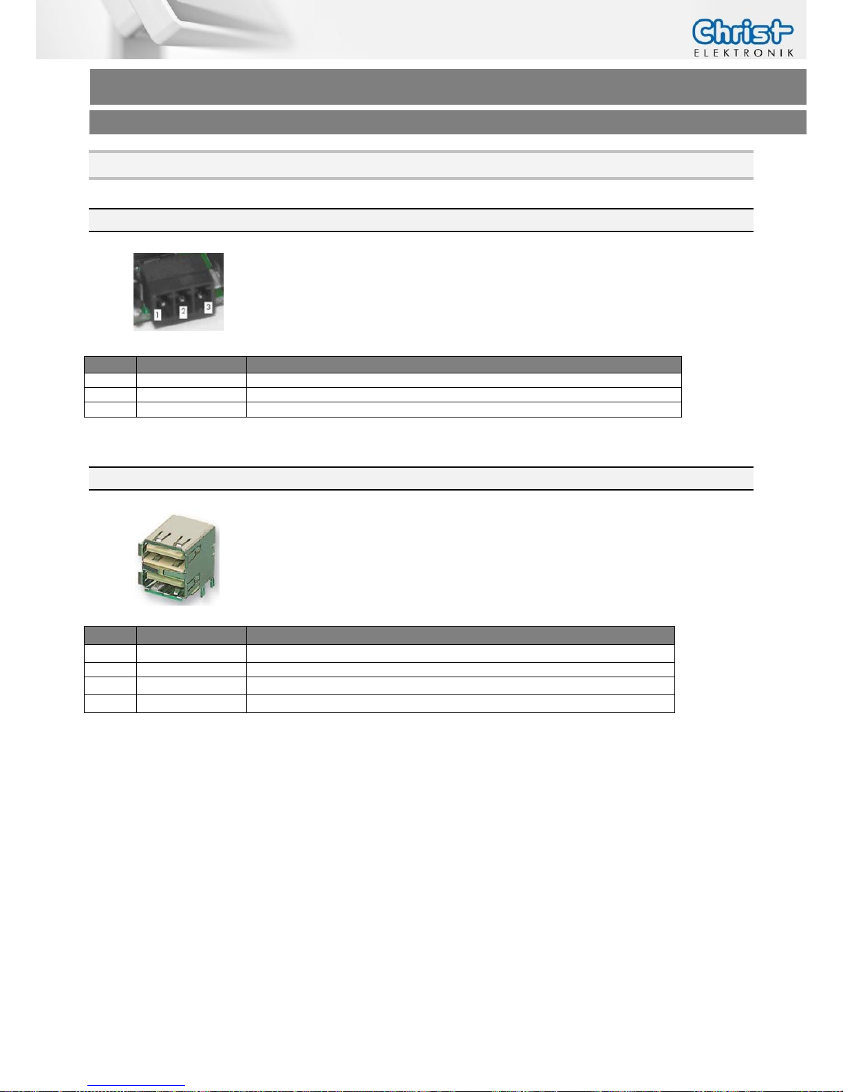
5.1 Power Supply Connector
Mating
Connector
Phoenix Connector MC 1.5/3-ST-3.5
or
Phoenix Connector MC 1,5/3-STF-3.5
(only screwable version)
Pin
Function
Description
1
GND
Power Supply GND
2
PE
PE
3
VCC
Power Supply VCC
5.2 USB 2.0 Type A Connector
Type
Double USB Type A
Pin
Function
Description
1
VBUS
USB VCC
2
D-
USB Data-
3
D+
USB Data+
4
GND
USB GND
Page 36
Touch-it XELO
Operating Instructions
Copyright / © Christ-Elektronik GmbH 36 / 44 Sep. 2015, Revision 12
a member of the Christ Company Group Document No.: E461201
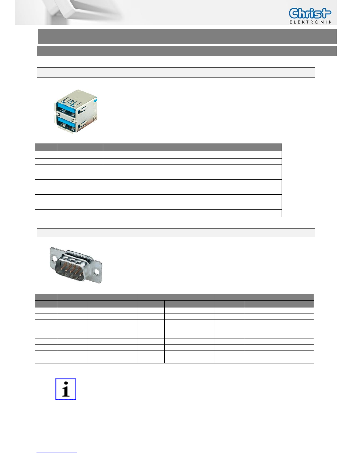
5.3 USB 3.0 Type A Connector
Type
Double USB 3.0 Type A
Pin
Function
Description
1
VBUS
USB VCC
2
D-
USB Data-
3
D+
USB Data+
4
GND
USB GND
5
StdA_SSRX-
SuperSpeed transmitter differential pair
6
StdA_SSRX+
SuperSpeed transmitter differential pair
7
GND_DRAIN
Ground for signal return
8
StdA_SSTX-
SuperSpeed receiver differential pair
9
StdA_SSTX+
SuperSpeed receiver differential pair
5.4 COM Connector
Type
D-SUB ST 09
RS-232
RS-485
RS-422
Pin
Function
Description
Function
Description
Function
Description
1
DCD
Data Carrier Detect
DATA-
Data differntial pair A
Rx+
Receiver differential pair +
2
RX
Receive Data
DATA+
Data differntial pair B
Rx-
Receiver differential pair -
3
TX
Transmit Data
n.c. Tx+
Transmitter differential pair+
4
DTR
Data Terminal Ready
n.c. Tx-
Transmitter differential pair-
5
GND
Ground
GND
Ground
GND
Ground
6
DSR
Data Set Ready
n.c. n.c.
7
RTS
Request to Send
n.c. n.c. 8
CTS
Clear to Send
n.c. n.c.
9
RI
Ring Indicator
n.c. n.c.
INFORMATION!
RS-485 / RS- 422 only with CPU GX-415GA and i5-5300U
Page 37
Touch-it XELO
Operating Instructions
Copyright / © Christ-Elektronik GmbH 37 / 44 Sep. 2015, Revision 12
a member of the Christ Company Group Document No.: E461201
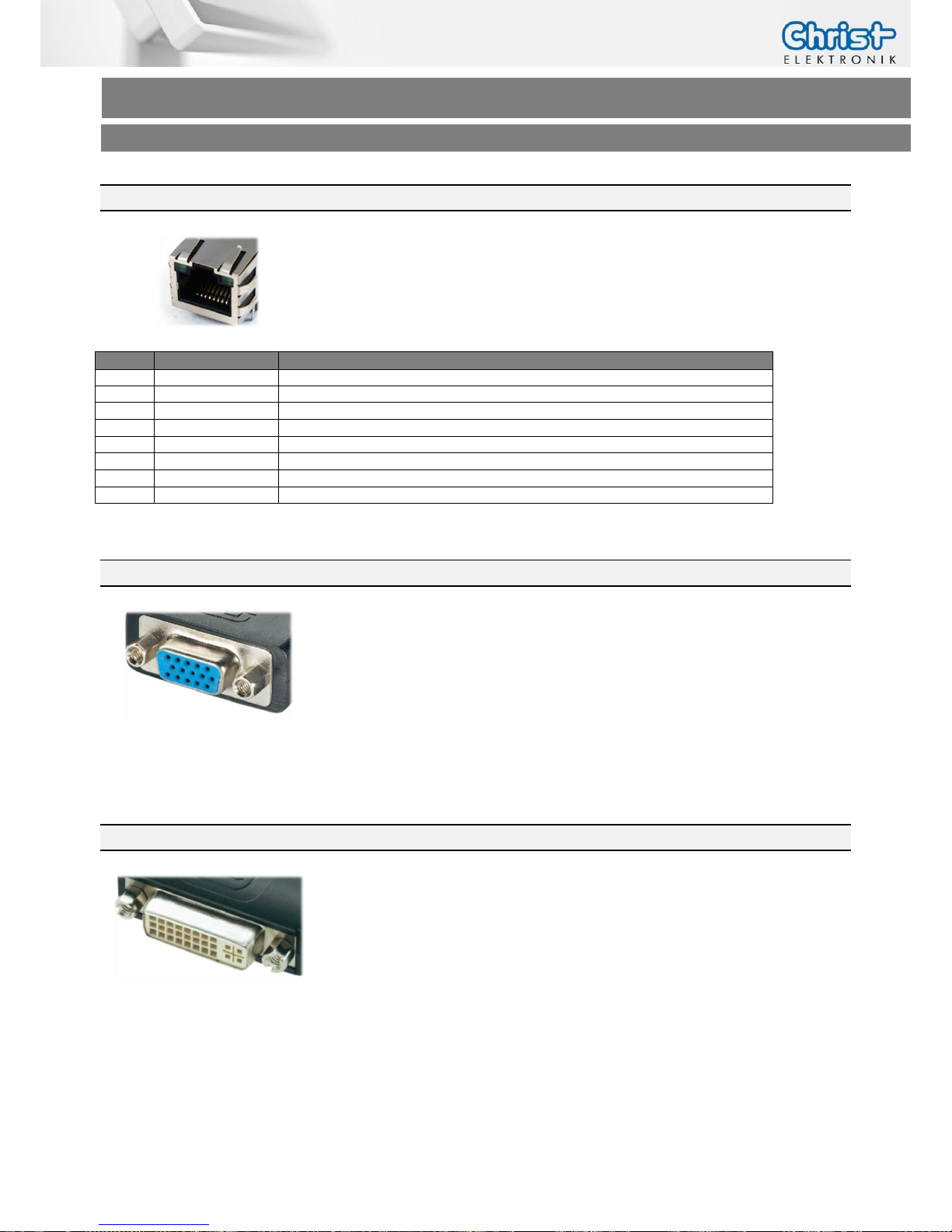
5.5 Ethernet Connector
Type
1 Gigabit Ethernet RJ45 Tab-up with LED
Pin
Function
Description
1
D1+
Transmit Data+
2
D1-
Transmit Data -
3
D2+
Receive Data +
4
D3+
Bidirectional+
5
D3-
Bidirectional-
6
D2-
Receive Data -
7
D4+
Bidirectional+
8
D4-
Bidirectional-
5.6 VGA Connector
Type
VGA Connector
The VGA interface is equal with the standard VGA pin assignment.
5.7 DVI-I Connector
Type
DVI-I Connector
The DVI-I interface is equal with the standard DVI pin assignment.
Page 38
Touch-it XELO
Operating Instructions
Copyright / © Christ-Elektronik GmbH 38 / 44 Sep. 2015, Revision 12
a member of the Christ Company Group Document No.: E461201
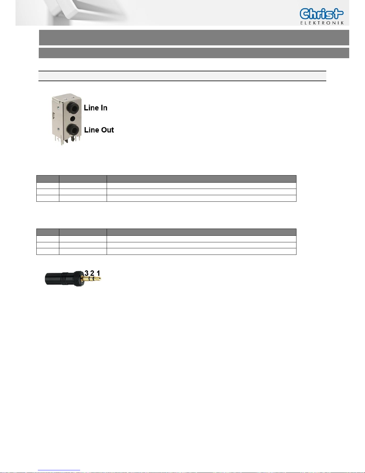
5.8 Line In / Line Out
Type
SJD-3512-33
Line In
Pin
Function
Description
1
Line In L
Audio In Left
2
Line In R
Audio In Right
3
GND
Ground
Line Out
Pin
Function
Description
1
Line Out L
Audio Out Left
2
Lin Out R
Audio Out Right
3
GND
Ground
Page 39
Touch-it XELO
Operating Instructions
Copyright / © Christ-Elektronik GmbH 39 / 44 Sep. 2015, Revision 12
a member of the Christ Company Group Document No.: E461201
6 Pointers
6.1 Used symbols
Symbols
The following symbols are used in this instruction manual:
DANGER!
Denotes a direct threat of danger. Not observing this pointer may be life
threatening or lead to serious injuries.
CAUTION!
Denotes a possibly dangerous situation. Not observing this pointer can
cause minor injuries or lead to material damages.
INFORMATION!
Denotes application pointers and other useful information.
6.2 General pointers
INFORMATION!
This device was manufactured according to DIN EN ISO 9001 and left the
factory in a perfect state.
In order to maintain this state and to assure the safe operation, the user
must consider the pointers and warning remarks, which are contained in
this instruction manual.
INFORMATION!
Displays may contain defect pixels from the manufacturing process.
These lacks aren´t reasons for a warranty.
Page 40
Touch-it XELO
Operating Instructions
Copyright / © Christ-Elektronik GmbH 40 / 44 Sep. 2015, Revision 12
a member of the Christ Company Group Document No.: E461201
6.3 Safety pointers
DANGER!
In the case of damage of the device, shut it down and disconnect it immediately from the supply voltage.
Disconnect every connection line and send it back to Christ-Elektronik
GmbH.
DANGER!
Avoid any penetration of liquid or dust.
Do not expose the device to humidity for a long time!
DANGER!
Danger of explosion when the battery is replaced with the wrong type.
Replace the battery only with a Lithium battery with the same or equivalent type. Contact Christ-Elektronik for suitable battery types.
Intended Use
These products are not designed, developed and produced for use, which
pose fatal risks and dangers that may cause death, injuries, serious physical impairments or other loss, if no exceptional security measures are ensured. Thus there are limitations for use in the monitoring of nuclear reactions in nuclear power plants, flight control systems, air traffic control, in
the control of mass transportation, medical life support systems and control of weapon systems.
Page 41
Touch-it XELO
Operating Instructions
Copyright / © Christ-Elektronik GmbH 41 / 44 Sep. 2015, Revision 12
a member of the Christ Company Group Document No.: E461201
CAUTION!
If the device is used for other purposes or incorrectly operated,
Christ-Elektronik GmbH will not hold damages liable.
Do not operate the touch-sensitive surface of the screen with any abrasive
or sharp-edged objects.
Protect the Touch-it Panel PC against caustic chemicals and long solar
radiation.
CAUTION!
Never cover the Touch-it Panel PC completely or build it in a small closed
and unvented housing.
CAUTION!
This is a Class A product. In a domestic environment this product may
cause radio interference, in which case the user may be required to take
adequate measures.
INFORMATION!
Please check immediately:
Is the device damaged or is any equipment missing?
(See chapter Commissioning)
In the case of defect please inform us immediately.
Page 42
Touch-it XELO
Operating Instructions
Copyright / © Christ-Elektronik GmbH 42 / 44 Sep. 2015, Revision 12
a member of the Christ Company Group Document No.: E461201
6.4 FCC Conformity (only Devices with FCC compliance)
INFORMATION!
The FCC Conformity is only valid for Devices with FCC compliance!
Operation is subject to the following two conditions:
(1) this device may not cause harmful interference, and
(2) this device must accept any interference received, including
interference that may cause undesired operation.
This equipment has been tested and found to comply with the limits for
Class A digital device, pursuant to part 15 of the FCC rules. These limits
are designed to provide reasonable protection against harmful interference when the equipment is operated in a commercial environment. This
equipment generates, uses and can radiate radio frequency energy and, if
not installed and used in accordance with the instruction manual, may
cause harmful interference to radio communications. Operation of this
equipment in a residential area is likely to cause harmful interference in
which case the user will be required to correct the interference at his own
expense.
CAUTION!
Technological changes to the device may cause the loss of the
FCC Conformity.
Page 43
Touch-it XELO
Operating Instructions
Copyright / © Christ-Elektronik GmbH 43 / 44 Sep. 2015, Revision 12
a member of the Christ Company Group Document No.: E461201
6.5 Maintenance plan
INFORMATION!
Only the manufacturer (Christ-Elektronik GmbH) is allowed to replace the
internal lithium battery.
The calibration of the analog resistive touch may be required from time to
time.
6.6 Repairs
DANGER!
Only the qualified staffs are allowed to carry out the repairs. The incorrect
repair may lead to serious danger for the user.
6.7 Cleaning
DANGER!
Disconnect the Touch-it Panel PC from the supply voltage before cleaning.
CAUTION!
Do not clean the touch-sensitive surface of the monitor with detergents
containing solvent or acid.
INFORMATION!
Use a humid and soft cloth with gentle soap suds to clean.
Page 44
Touch-it XELO
Operating Instructions
Copyright / © Christ-Elektronik GmbH 44 / 44 Sep. 2015, Revision 12
a member of the Christ Company Group Document No.: E461201
DISCLAIMER
Technical data are subject to modification and delivery subject to availability. Any liability that the data and illustrations are
complete, actual or correct is excluded. Designations may be trademarks and/or copyrights of the respective manufacturer,
the use of which by third parties for their own purposes may infringe the rights of such owner.
 Loading...