

Page 1
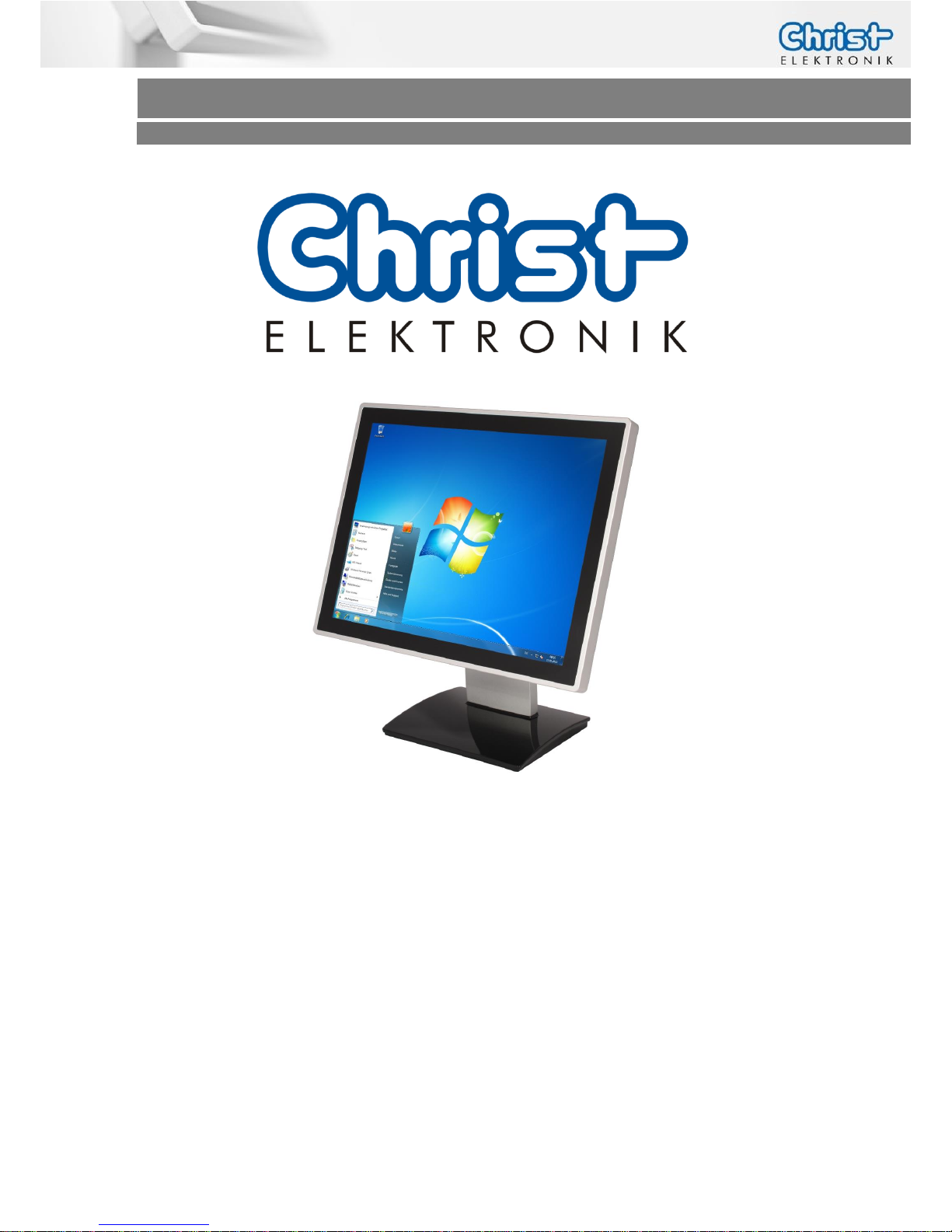
Touch-it Monitor
Operating Instructions
Touch-it Monitor
Easy Integration
Touch Interface
24VDC Input Voltage
DVI and VGA Input
Page 2

Touch-it Monitor
Operating Instructions
Document No.
E461301
Revision
01
Date
12 Mar. 14
Address
Christ-Elektronik GmbH
Alpenstraße 34
DE-87700 Memmingen
Telephone
+49 (0)8331 8371 – 0
Fax
+49 (0)8331 8371 – 99
E-Mail
Internet
http://www.christ-elektronik.de
Copyright
No part of this documentation may in any form be reproduced, nor used,
copied or distributed by means of electronic systems without previous
written permission by Christ-Elektronik GmbH. The translation into another language also requires a written permission. This documentation
may be exclusively entrusted to the owner of the installation or to the
employees of Christ-Elektronik GmbH.
Technical changes
Christ-Elektronik GmbH reserves the right to change specifications, executions and technical data held within this document without prior notice.
Trademarks
Brand and product names are trademarks or registered trademarks of
their respective owners.
Page 3

Touch-it Monitor
Operating Instructions
Table of contents
Page
1 General .................................................................................................................. 4
Overview ............................................................................................................................. 4
Power Supply ...................................................................................................................... 5
Mechanical & Environmental ............................................................................................ 5
2 Commissioning ...................................................................................................... 6
2.1 Mounting ................................................................................................................... 6
2.1.1 Touch-it XELO Open Frame / Open Frame glass ..................................................................... 6
2.1.2 Touch-it XELO Front Panel / Front Panel glass ......................................................................... 7
2.1.3 Touch-it XELO VESA / VESA glass ................................................................................................. 8
2.2 Interfaces Connector Side ..................................................................................... 9
3 Software ............................................................................................................... 10
3.1 Video Signal ............................................................................................................ 10
3.2 Touch Driver ............................................................................................................. 11
4 Touch Calibration ................................................................................................ 13
4.1 Foil Touch analog resistive ....................................................................................... 13
4.2 Projected Capacitive Touch ...................................................................................... 13
5 Interfaces ............................................................................................................. 14
5.1 Power Supply Connector...................................................................................... 14
5.2 VGA Connector ..................................................................................................... 14
5.3 DVI Connector ....................................................................................................... 14
5.4 USB Type B Connector ........................................................................................... 15
6 Pointers ................................................................................................................ 16
6.1 Used symbols ............................................................................................................ 16
6.2 General pointers ....................................................................................................... 16
6.3 Safety pointers .......................................................................................................... 17
6.4 Maintenance plan ..................................................................................................... 18
6.5 Repairs ...................................................................................................................... 18
6.6 Cleaning .................................................................................................................... 19
Page 4
Touch-it Monitor
Operating Instructions
1 General
OVERVIEW
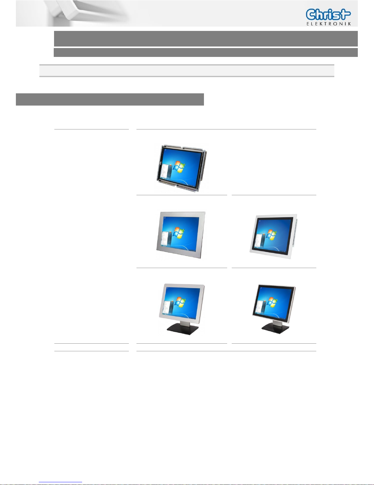
Series
Touch-it Monitor
Housing
Open Frame
Open Frame glass
(on request)
Front Panel
Front Panel glass
VESA
VESA glass
Touch
Foil Touch, analog resistive
Projected Capacitive Touch
Sizes
(Display)
10.4” (26.4 cm)
15” (38.1 cm)
21.5” (54.6 cm)
Page 5
Touch-it Monitor
Operating Instructions
POWER SUPPLY
Supply Voltage
24 VDC ± 20%
Power Dissipation
See specific datasheet
Power Switch
No
MECHANICAL & ENVIRONMENTAL
Open Frame
Open Frame glass
Housing Front Without Frame
Without Frame
Housing
Stainless steel
Stainless steel
Cooling
Passive
Passive
Protection Class
IP20
IP20
Operating Temperature
0 ~ 40 °C
0 ~ 40 °C
Front Panel
Front Panel glass
Housing Front
Aluminium frame / naturally anodized
Glass, black frame
Housing
Stainless steel
Stainless steel
Cooling
Passive
Passive
Protection Class
IP20 (IP 65 front)
IP20 (IP 65 front)
Operating Temperature
0 ~ 40 °C
0 ~ 40 °C
VESA
VESA glass
Housing Front ---
Glass, black frame
Housing
Aluminium / anodized silver, chemi-
cally shined
Aluminium / anodized silver,
chemically shined
Cooling
Passive
Passive
Protection Class
IP20 (IP 65 front)
IP20 (IP 65 front)
Operating Temperature
0 ~ 40 °C
0 ~ 40 °C
Dimensions
See specific datasheet
Weight
See specific datasheet
Storage Temperature
-10 ~ 70 °C
Humidity
5 ~ 80% (non condensing)
Certification CE, EN55022, EN55024, DIN EN ISO 9001
Page 6
Touch-it Monitor
Operating Instructions
2 Commissioning
2.1 Mounting
2.1.1 Touch-it XELO Open Frame / Open Frame glass
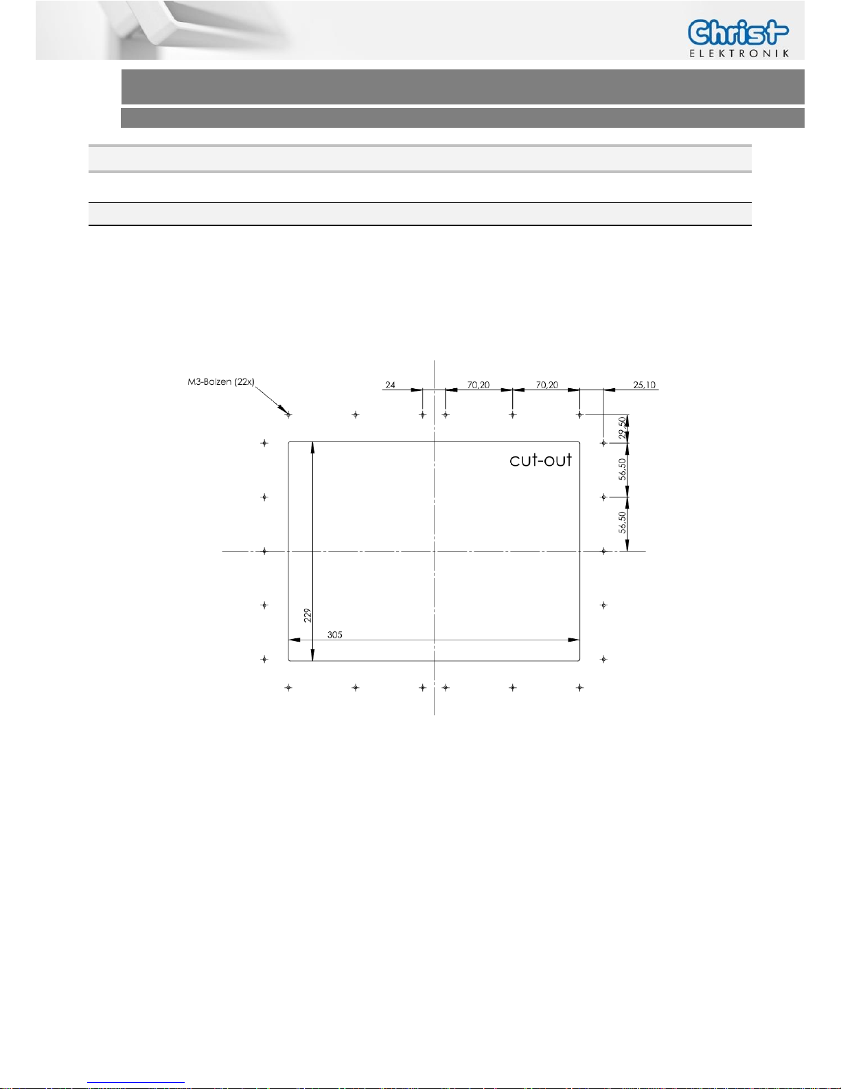
The variant Touch-it XELO Open Frame is designed for customer specific mounting.
Each Open Frame Panel has its own cut-out drawing.
For example:
For the appropriated drawing see the specific data sheet.
Page 7
Touch-it Monitor
Operating Instructions
2.1.2 Touch-it XELO Front Panel / Front Panel glass
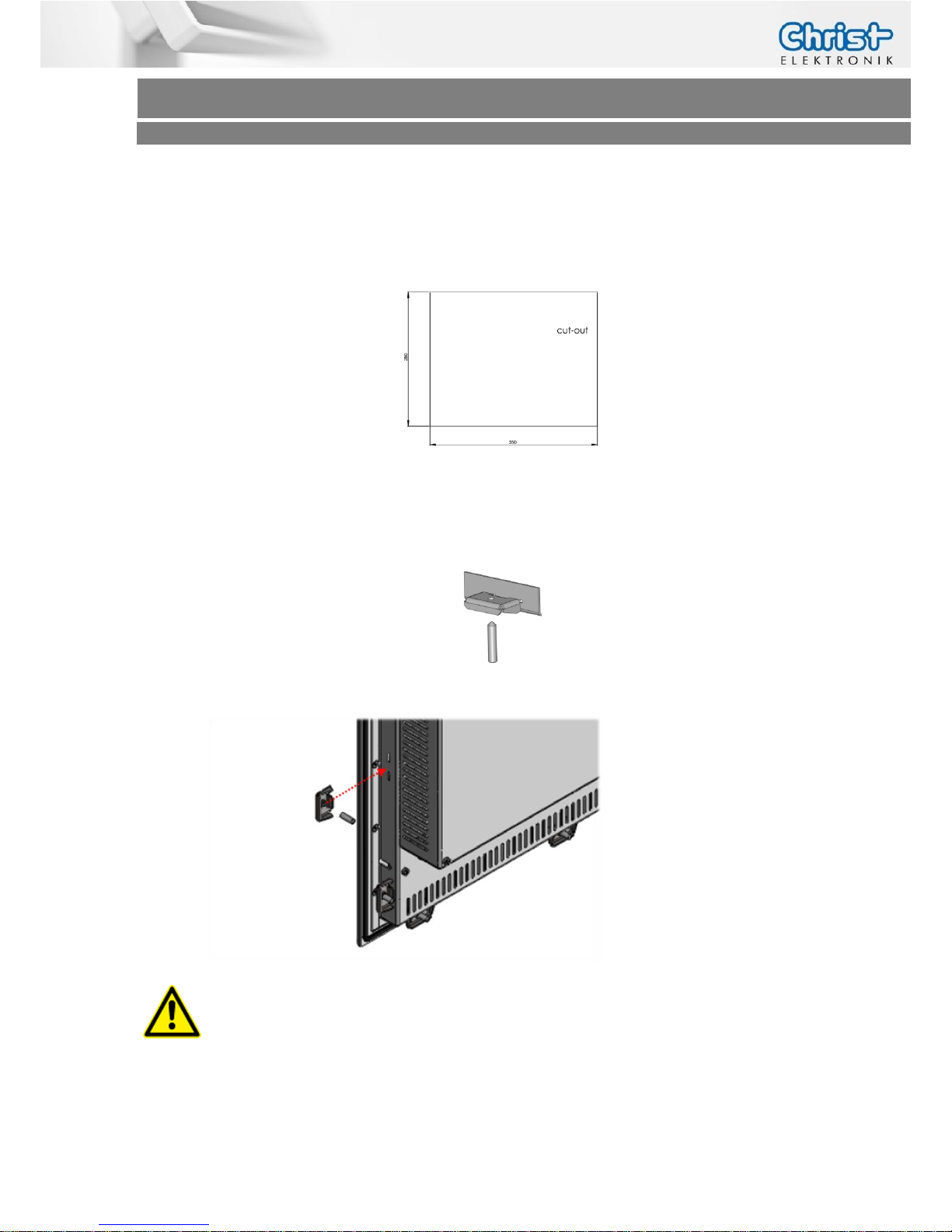
The variant Touch-it XELO Front Panel is designed for front mounting.
Each Front Panel has its own cut-out drawing.
For the appropriated drawing see the specific data sheet.
To clamp the Front Panel into the cut-out you can use the attached fasting clamps.
Fasting Clamp
CAUTION!
For the best installation result the use of all provided fasting
clamps is highly recommended. Depending on individual installation circumstances a new IP rating may be considered.
Page 8
Touch-it Monitor
Operating Instructions
2.1.3 Touch-it XELO VESA / VESA glass
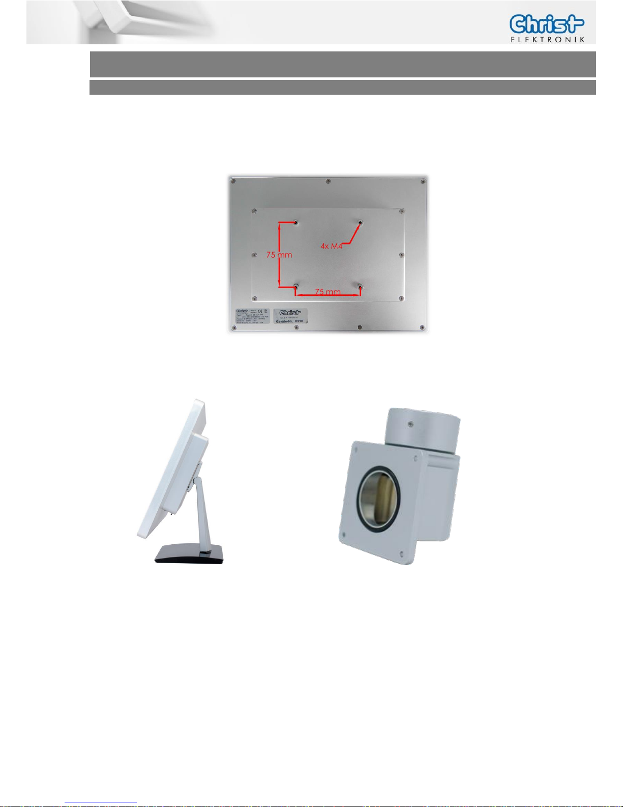
The variant Touch-it XELO VESA is designed for VESA75 mount.
Suitable mounting variants are:
VESA Desk Stand Arm Mounting System VESA-SA75
Page 9
Touch-it Monitor
Operating Instructions
2.2 Interfaces Connector Side
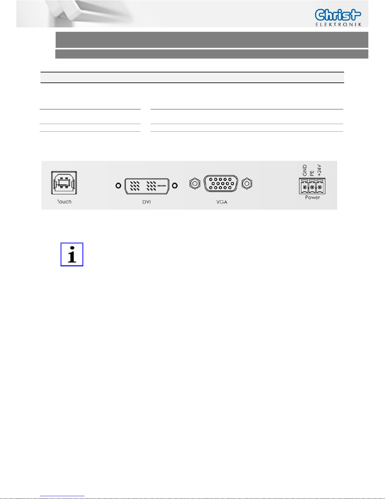
USB
1 x USB Device (Type B, Touch-Control)
Video
1 x DVI-D
1 x VGA
Control Button
Power, Left, Right, Menu, Auto
Power Connector
Phoenix
Connector side Touch-it Monitor
All interfaces are described in the chapter Interfaces.
Page 10
Touch-it Monitor
Operating Instructions
3 Software
3.1 Video Signal
Adjust the VGA Video Signal
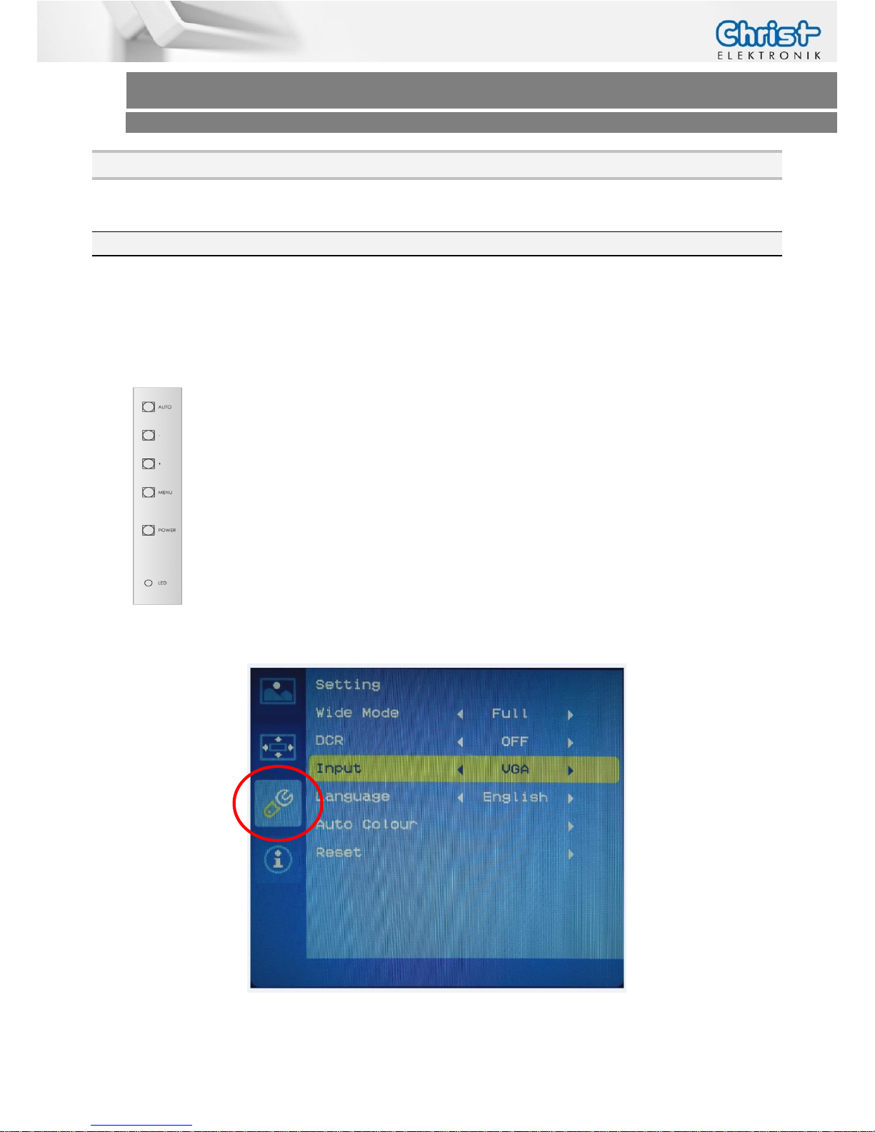
To adjust the best suited values press the AUTO button on the rear of the Touch Monitor.
Choose the right input signal
If the VGA and DVI connector is plugged into the Touch Monitor you have
to choose the input Signal.
Press the MENU button on the rear of the Touch Monitor to open the OSD
menu.
Select with “+” and “-“ the tab Setting and press MENU.
Select Input and choose your desired video signal.
With “AUTO” you can close the OSD menu.
Page 11
Touch-it Monitor
Operating Instructions
3.2 Touch Driver
1. Installation
Download the touch driver from:
www.eeti.com.tw ->Download->Driver-> choose your right driver
Then install the downloaded file on your computer.
2. Implementation
Plug the touch cable into the monitor and your PC.
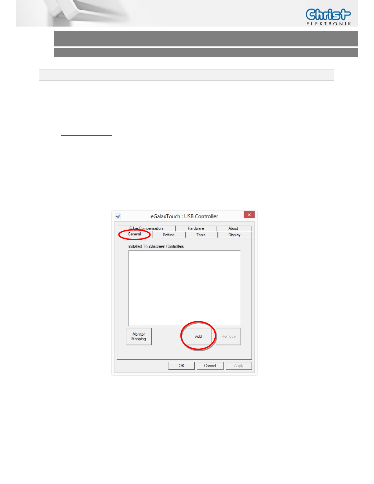
Open the eGalaxTouch Configure Utility (eGalaxTouch.exe) and press the “Add” button
under the General tab.
Page 12
Touch-it Monitor
Operating Instructions
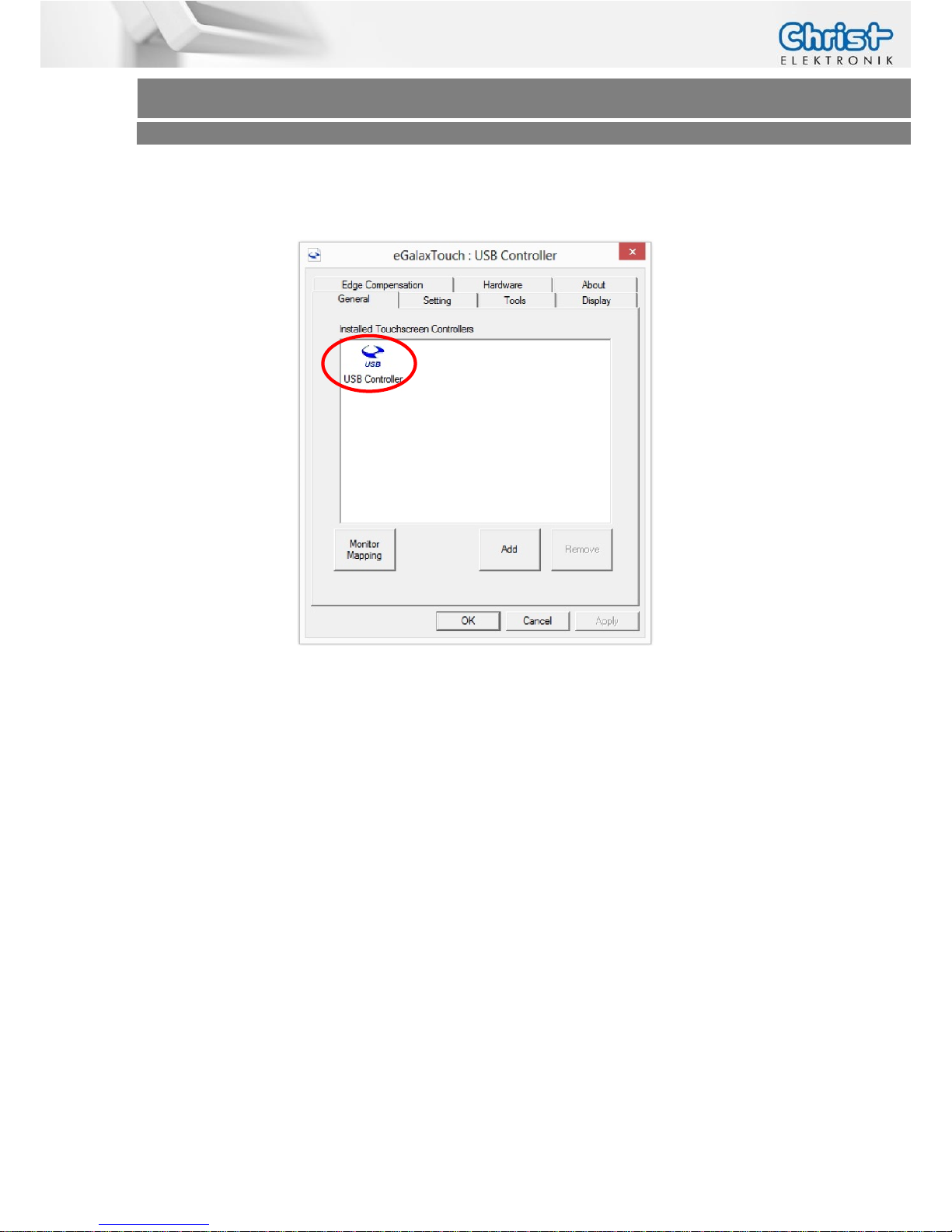
Now the USB Controller must occur. After the calibration your touch is ready to use.
(See Chapter Touch Calibration)
Page 13
Touch-it Monitor
Operating Instructions
4 Touch Calibration
4.1 Foil Touch analog resistive
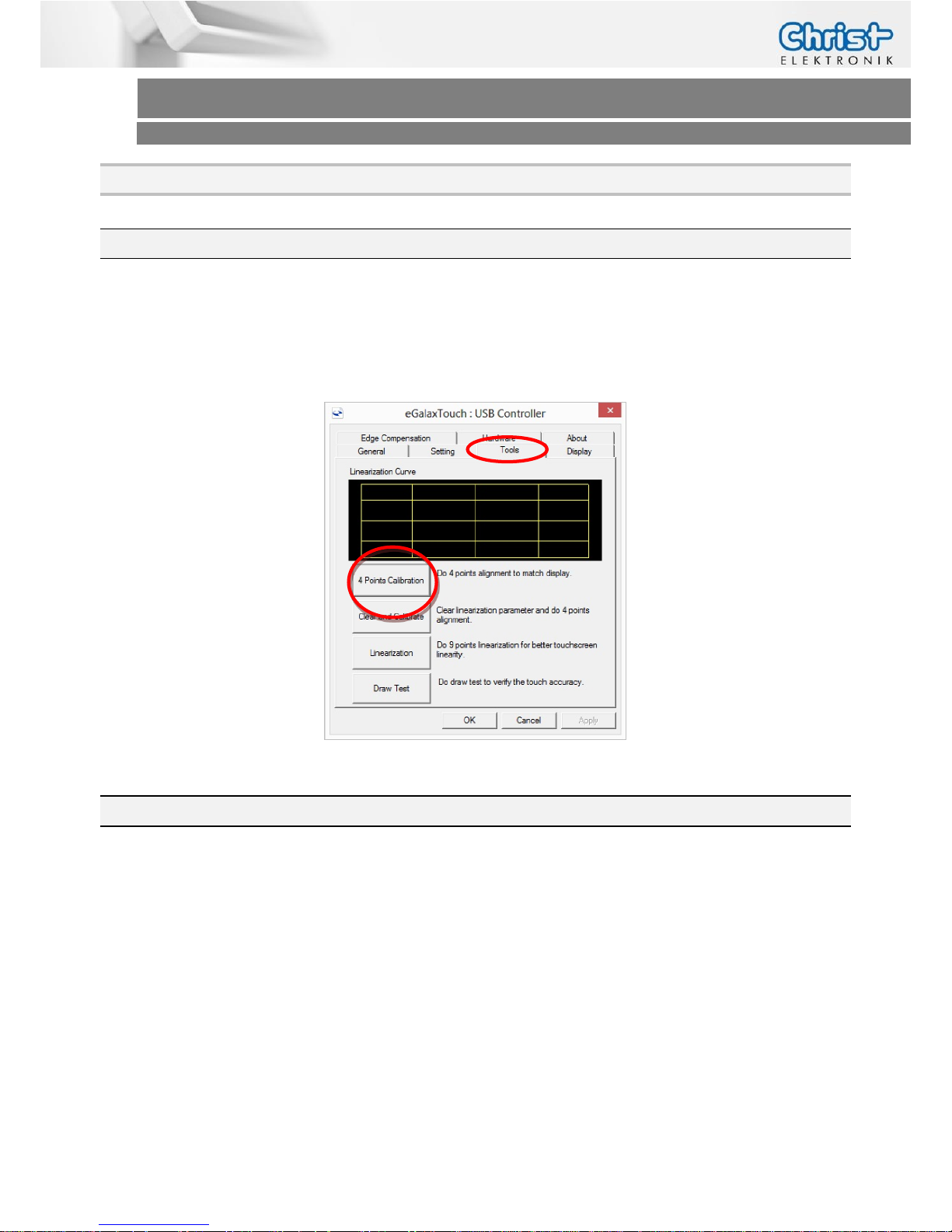
Open the eGalaxTouch Configure Utility (eGalaxTouch.exe) and press the “4 Points Calibration”
under the Tools tab. (See Chapter Software -> Touch Driver)
4.2 Projected Capacitive Touch
There is no need to calibrate the projected capacitive touch.
Page 14
Touch-it Monitor
Operating Instructions
5 Interfaces
5.1 Power Supply Connector
Mating
Connector
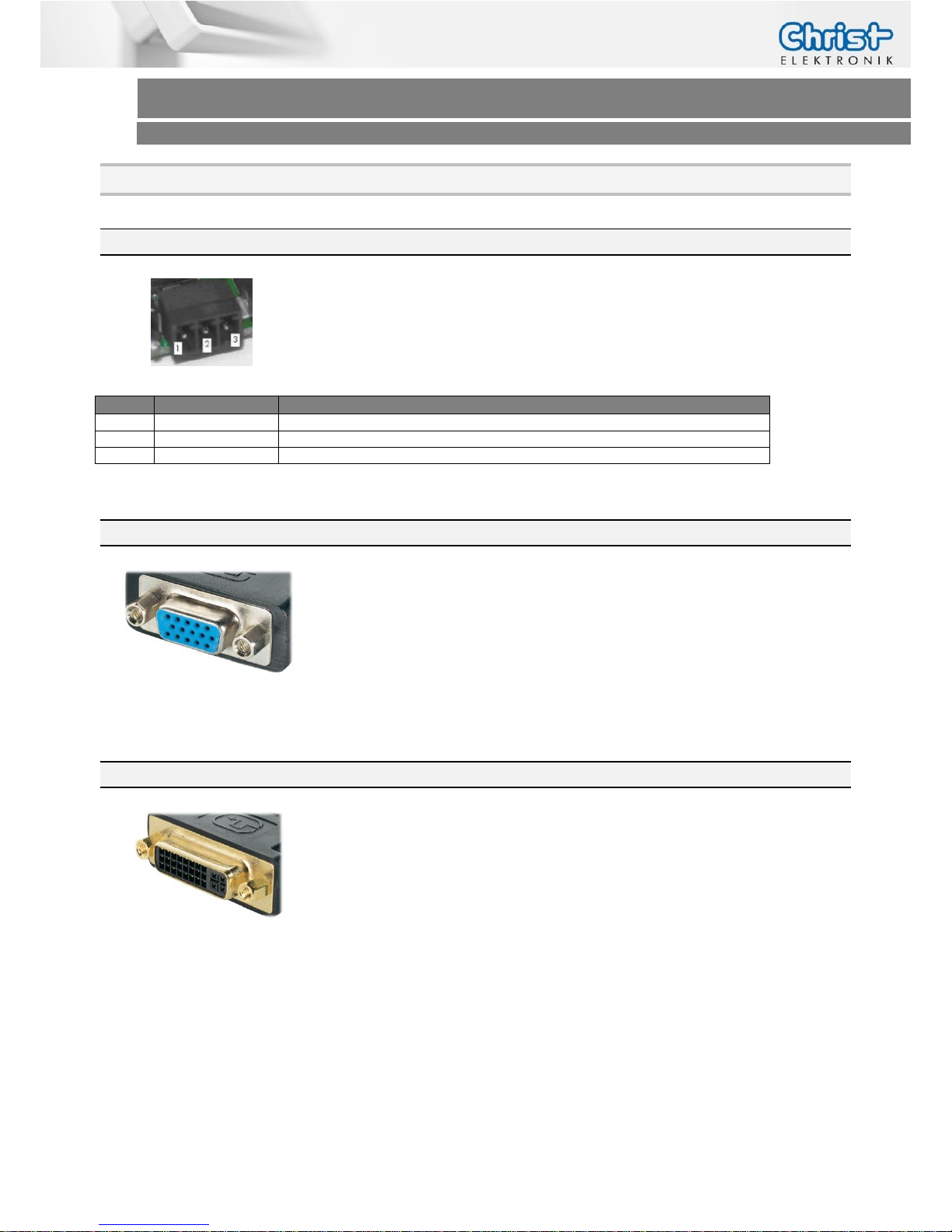
Phoenix Connector MC 1.5/3-ST-3.5
Pin
Function
Description
1
GND
Power Supply GND
2
PE
PE
3
VCC
Power Supply VCC
5.2 VGA Connector
Type
Mini Sub-D BU HD15
The VGA interface is equal with the standard VGA pin assignment.
5.3 DVI Connector
Type
DVI Female 24 + 1 pol.
The DVI interface is equal with the standard DVI pin assignment.
Page 15
Touch-it Monitor
Operating Instructions
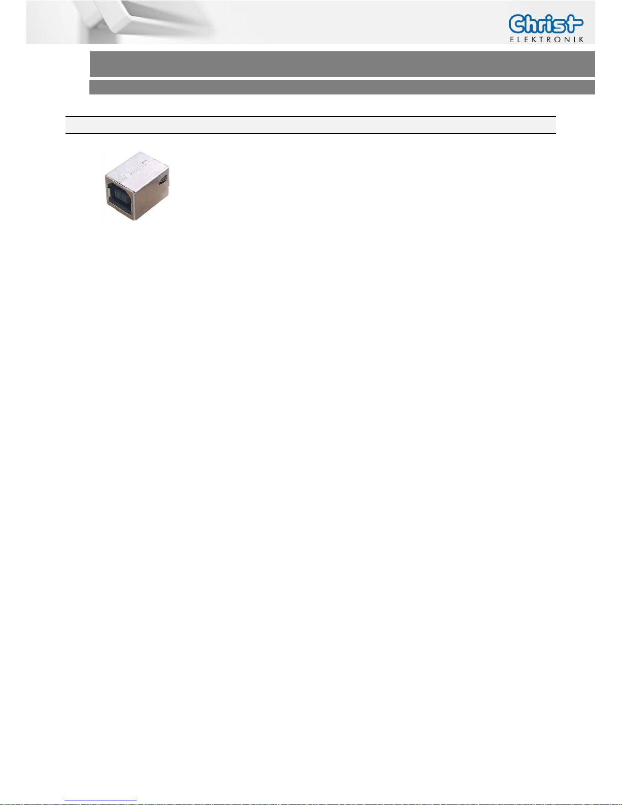
5.4 USB Type B Connector
Type
USB Type B
The USB Type B interface is equal with the standard USB Type B pin assignment.
Page 16
Touch-it Monitor
Operating Instructions
6 Pointers
6.1 Used symbols
Symbols
The following symbols are used in this instruction manual:
DANGER!
Denotes a direct threat of danger. Not observing this pointer may be life
threatening or lead to serious injuries.
CAUTION!
Denotes a possibly dangerous situation. Not observing this pointer can
cause minor injuries or lead to material damages.
INFORMATION!
Denotes application pointers and other useful information.
6.2 General pointers
INFORMATION!
This device was manufactured according to DIN EN ISO 9001 and left the
factory in a perfect state.
In order to maintain this state and to assure the safe operation, the user
must consider the pointers and warning remarks, which are contained in
this instruction manual.
INFORMATION!
Displays may contain defect pixels from the manufacturing process.
These lacks aren´t reasons for a warranty.
Page 17
Touch-it Monitor
Operating Instructions
6.3 Safety pointers
DANGER!
In the case of damage of the device, shut it down and disconnect it immediately from the supply voltage.
Disconnect every connection line and send it back to Christ-Elektronik
GmbH.
DANGER!
Avoid any penetration of liquid or dust.
Do not expose the device to humidity for a long time!
Intended Use
These products are not designed, developed and produced for use, which
pose fatal risks and dangers that may cause death, injuries, serious physical impairments or other loss, if no exceptional security measures are ensured. Thus there are limitations for use in the monitoring of nuclear reactions in nuclear power plants, flight control systems, air traffic control, in
the control of mass transportation, medical life support systems and control of weapon systems.
CAUTION!
If the device is used for other purposes or incorrectly operated,
Christ-Elektronik GmbH will not hold damages liable.
Do not operate the touch-sensitive surface of the screen with any abrasive
or sharp-edged objects.
Protect the Touch-it Monitor against caustic chemicals and long solar radiation.
Page 18
Touch-it Monitor
Operating Instructions
CAUTION!
This is a Class A product. In a domestic environment this product may
cause radio interference, in which case the user may be required to take
adequate measures.
INFORMATION!
Please check immediately:
Is the device damaged or is any equipment missing?
(See chapter Commissioning)
In the case of defect please inform us immediately.
6.4 Maintenance plan
INFORMATION!
Only the manufacturer (Christ-Elektronik GmbH) is allowed to replace the
internal lithium battery.
The calibration of the analog resistive touch may be required from time to
time.
6.5 Repairs
DANGER!
Only the qualified staffs are allowed to carry out the repairs. The incorrect
repair may lead to serious danger for the user.
Page 19
Touch-it Monitor
Operating Instructions
6.6 Cleaning
DANGER!
Disconnect the Touch-it Monitor from the supply voltage before cleaning.
CAUTION!
Do not clean the touch-sensitive surface of the monitor with detergents
containing solvent or acid.
INFORMATION!
Use a humid and soft cloth with gentle soap suds to clean.
Page 20
Touch-it Monitor
Operating Instructions
Christ-Elektronik GmbH 20 / 20 März 2014, Revision 1
[email protected] Document No.: E461201
Contact
Christ – Elektronik GmbH
Alpenstraße 34
D-87700 Memmingen
Tel. +49 (0)8331/8371-0
http://www.christ-elektronik.de
More Information
Learn more about
Christ – Elektronik Touch-it
solutions, please contact your
Christ – Elektronik GmbH sales
representative or visit our website.
http://www.christ-elektronik.de
Contact
Christ – Elektronik GmbH
Alpenstraße 34
D-87700 Memmingen
Tel. +49 (0)8331/8371-0
Website:
http://www.christ-elektronik.de
Copyrights
All rights reserved, including intellectual property rights. Changes to
technical data reserved. Delivery
subject to availability
Copyright © Christ – Elektronik
GmbH
Disclaimer
Technical data are subject to modification and delivery subject to
availability. Any liability that the
data and illustrations are complete,
actual or correct is excluded. Designations may be trademarks
and/or copyrights of the respective
manufacturer, the use of which by
third parties for their own purposes
may infringe the rights of such
owner
 Loading...