

Page 1
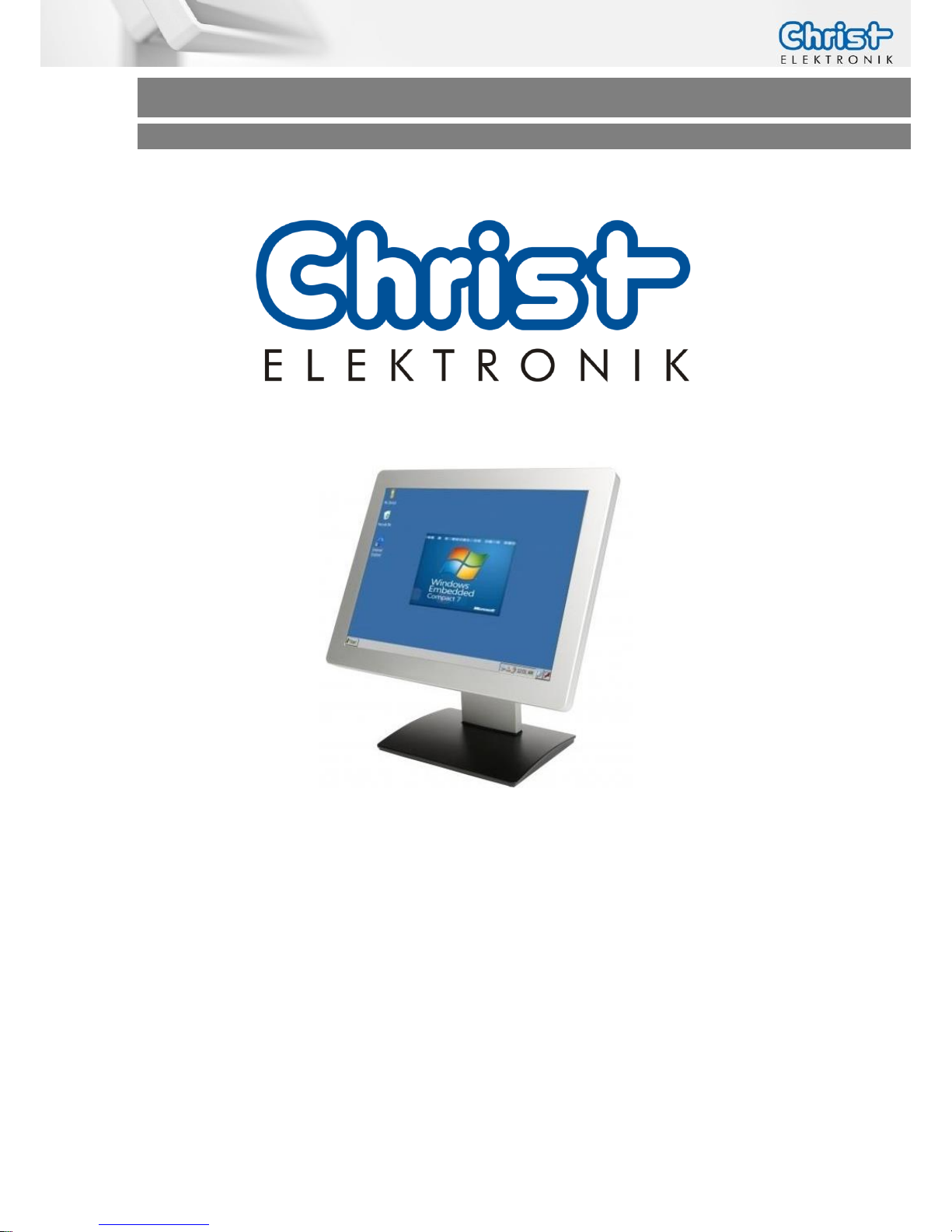
Touch-it CE
Operating Instructions
Touch-it CE
Low Power Panel PC
Different Housings
Sizes From 7” to 15”
Ready For Use
Page 2

Touch-it CE
Operating Instructions
Document No.
E461131
Revision
10
Date
23 Apr. 15
Address
Christ-Elektronik GmbH
Alpenstraße 34
DE-87700 Memmingen
Telephone
+49 (0)8331 8371 – 0
Fax
+49 (0)8331 8371 – 99
E-Mail
Internet
http://www.christ-elektronik.de
Copyright
No part of this documentation may in any form be reproduced, copied or
distributed by means of electronic systems without previous written permission by Christ-Elektronik GmbH. The translation into another language also
requires a written permission. This documentation may be exclusively entrusted to the owner of the installation or to the employees of ChristElektronik GmbH.
Technical changes
Christ-Elektronik GmbH reserves the right to change specifications, executions and technical data held within this document without prior notice.
Trademarks
Brand and product names are trademarks or registered trademarks of their
respective owners.
Page 3

Touch-it CE
Operating Instructions
Table of Contents
Page
1 General ..............................................................................................................................................4
2 Commissioning ................................................................................................................................7
2.1 Mounting .................................................................................................................................................... 7
2.1.1 Touch-it CE Open Frame ........................................................................................................ 7
2.1.2 Touch-it CE Front Panel .......................................................................................................... 8
2.1.3 Touch-it CE VESA .................................................................................................................. 9
2.2 Interfaces Connector Side ................................................................................................................. 10
3 Software .........................................................................................................................................11
3.1 Microsoft Windows Mobile Device Center / Active Sync ..................................................................... 11
3.2 General Information ................................................................................................................................ 13
3.2.1 Exploring the different interfaces that Windows CE offers ......................................................... 13
3.2.2 PC Connectivity over Ethernet ............................................................................................... 14
3.2.3 Compilation / Debugging .................................................................................................... 15
3.3 Flash Memory Layout............................................................................................................................... 17
3.4 Permanent Storage .................................................................................................................................. 18
3.4.1 Flash Disk .......................................................................................................................... 19
3.4.2 MicroSD Card .................................................................................................................... 19
3.4.3 USB HD ............................................................................................................................. 19
3.5 Registry .................................................................................................................................................... 20
3.6 Windows CE 6.0/ EC 7 Bootloader & Image Update.......................................................................... 21
3.6.1 Image Update via external memory (USB, SD) ......................................................................... 21
3.6.2 Image Update via terminal connection ................................................................................... 22
3.7 Running Applications at Startup (Autorun) ............................................................................................. 23
3.8 Adding Files to Desktop or Start Menu (AutoCopy) ............................................................................... 23
3.9 Touch-it CE remote control ...................................................................................................................... 24
4 Interfaces .........................................................................................................................................26
4.1 Power Supply Connector.................................................................................................................... 26
4.2 Ethernet Connector ............................................................................................................................. 26
4.3 CAN Connector.................................................................................................................................... 27
4.4 COM1 (RS-232) ...................................................................................................................................... 27
4.5 COM1 (RS-232, Touch-it CE Codesys) .............................................................................................. 28
4.6 COM2 (RS-485, Touch-it CE Codesys) .............................................................................................. 28
4.7 COM2 (RS-232 or RS-485) .................................................................................................................... 29
4.8 USB Type A ............................................................................................................................................. 30
4.9 USB Mini Type B Extern ......................................................................................................................... 30
4.10 Connector ............................................................................................................................................. 31
4.11 MircoSD .................................................................................................................................................. 31
4.12 I/O Connector ...................................................................................................................................... 32
5 Pointers ...........................................................................................................................................33
5.1 Used symbols ........................................................................................................................................... 33
5.2 General pointers ...................................................................................................................................... 33
5.3 Safety pointers ...................................................................................................................................... 34
5.4 Maintenance plan ............................................................................................................................... 35
5.5 Repairs .................................................................................................................................................... 35
5.6 Cleaning ................................................................................................................................................ 36
Page 4
Touch-it CE
Operating Instructions
1 General
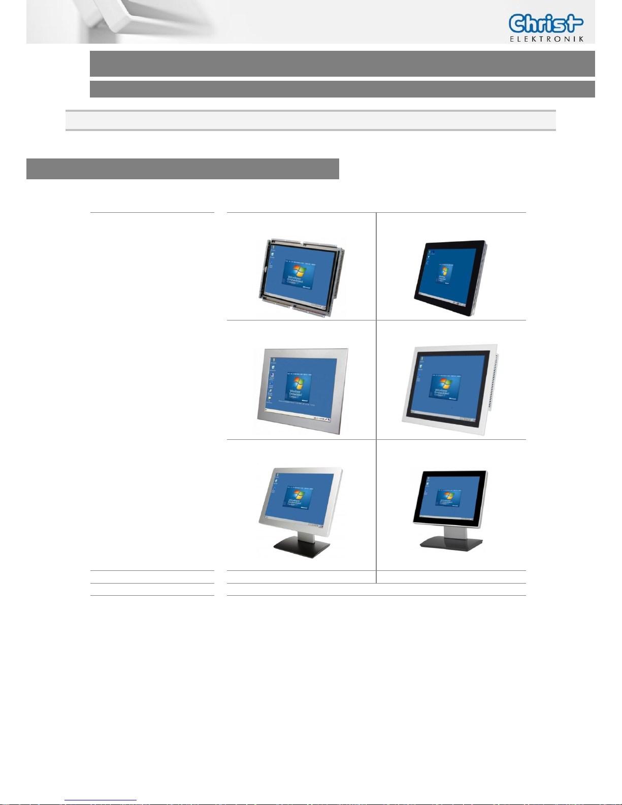
OVERVIEW
Series
Touch-it CE
Housing
Open Frame
Open Frame glass
Front Panel
Front Panel glass
VESA
VESA glass
Touch
Foil Touch, analog resistive
Projected Capacitive Touch
Sizes (Display)
7” – 15”
CPU
NVIDIA® Tegra™ 2 T20 Dual Core 1.0 GHz Cortex-A9
NVIDIA® Tegra™ 3 T30 Quad Core 1.4 GHz Cortex-A9
Page 5
Touch-it CE
Operating Instructions
SYSTEM
CPU
NVIDIA® Tegra™ 2 T20 Dual Core 1.0 GHz Cortex-A9
Graphic
Integrated Ultra-low power NVIDIA GeForce GPU
Video Decoder
H.264, WMV9 VC-1, MPEG-4, MPEG-2, H.263, DiVX, XviD
Memory
256 MB DDR2 RAM
512 MB DDR2 RAM (optional)
Storage
512 MB NAND FLASH
1 GB NAND FLASH (optional)
Operating System
Windows Embedded Compact 7 Pro
Linux (optional)
SYSTEM
CPU
NVIDIA® Tegra™ 3 T30 Quad Core 1.4 GHz Cortex-A9
Graphic
Integrated Ultra-low power NVIDIA GeForce GPU
Video Decoder
H.264, WMV9 VC-1, MPEG-4, MPEG-2, H.263, DiVX, XviD
Memory
1 GB DDR3 RAM
Storage
4 GB NAND FLASH
MicroSD
Operating System
Windows Embedded Compact 7 Pro
Linux (optional)
POWER SUPPLY
Supply Voltage
24 VDC ± 20%
Power Consumption
See specific datasheet
Power Switch
No
Page 6
Touch-it CE
Operating Instructions
MECHANICAL & ENVIRONMENTAL
Open Frame
Open Frame glass
Housing Front
Without Frame
Without Frame
Housing
Stainless Steel
Stainless Steel
Cooling
Passive
Passive
Protection Class
IP20 IP20
Operating Temperature
0 ~ 50 °C
0 ~ 50 °C
Front Panel
Front Panel glass
Housing Front
Aluminium frame /
naturally anodized
Glass, black frame
Housing
Stainless steel
Stainless steel
Cooling
Passive
Active
Protection Class
IP20 (IP 65 front)
IP20 (IP 65 front)
Operating Temperature
0 ~ 50 °C
0 ~ 50 °C
VESA
VESA glass
Housing Front
---
Glass, black frame
Housing
Aluminium / anodized silver,
chemically shined
Aluminium / anodized silver,
chemically shined
Cooling
Passive
Passive
Protection Class
IP20 (IP 65 front)
IP20 (IP 65 front)
Operating Temperature
0 ~ 50 °C
0 ~ 50 °C
Dimensions
See specific datasheet
Weight
See specific datasheet
Storage Temperature
-10 ~ 70 °C
Humidity
5 ~ 80% (non condensing)
Certification
CE, EN55022, EN55024, DIN EN ISO 9001
Page 7
Touch-it CE
Operating Instructions
2 Commissioning
2.1 Mounting
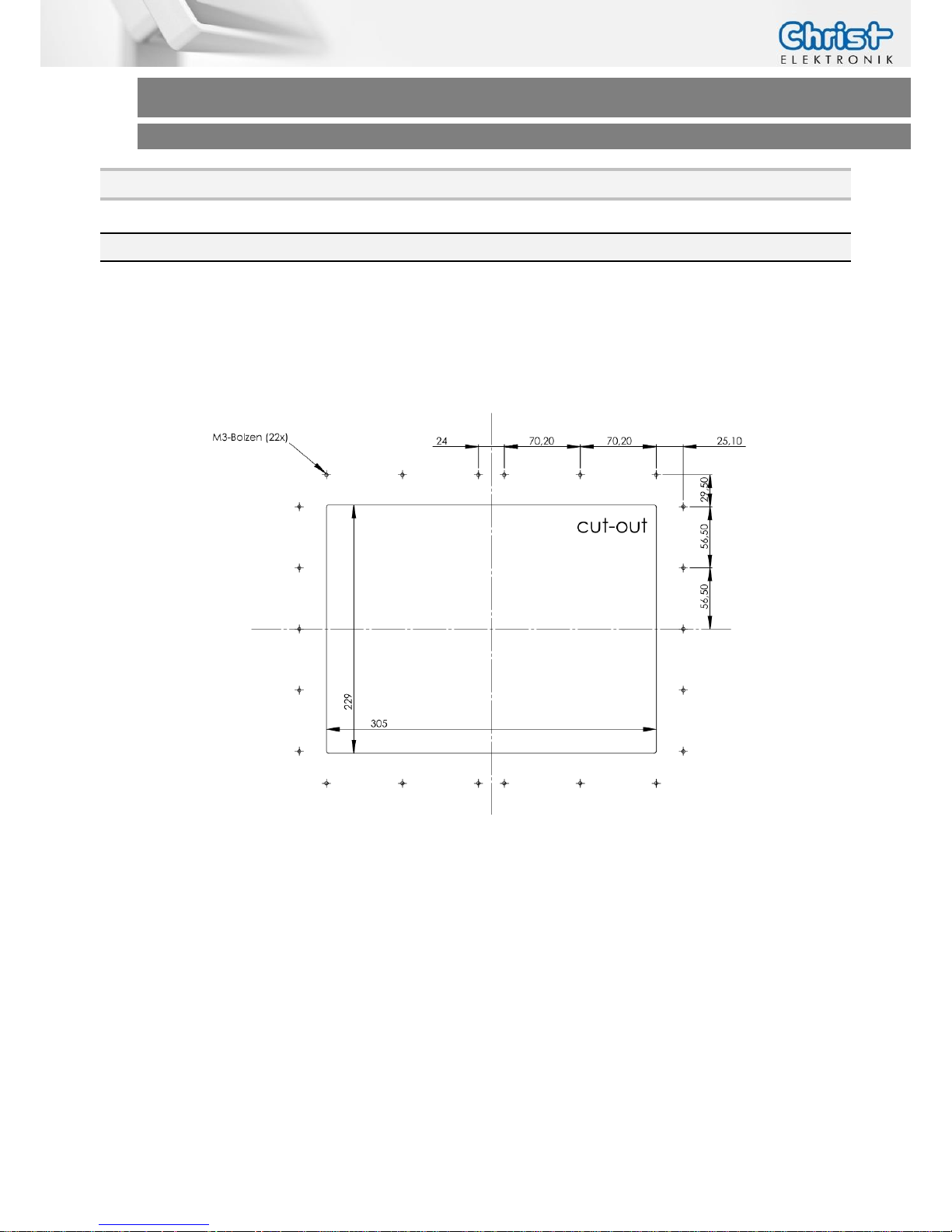
2.1.1 Touch-it CE Open Frame
The variant Touch-it CE Open Frame is designed for customer specific mounting.
Each Open Frame Panel has its own cut-out drawing.
For example:
For the appropriated drawing see the specific data sheet.
Page 8
Touch-it CE
Operating Instructions
2.1.2 Touch-it CE Front Panel
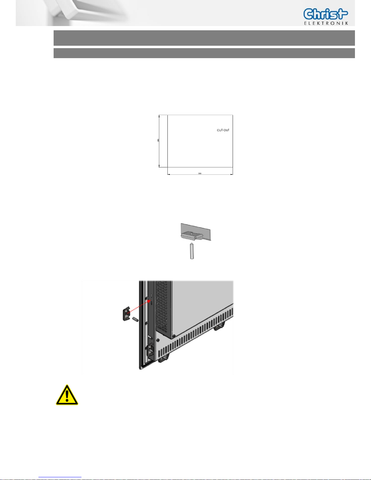
The variant Touch-it CE Front Panel is designed for front mounting.
Each Front Panel has its own cut-out drawing.
For the appropriated drawing see the specific data sheet.
To clamp the Front Panel into the cut-out you can use the attached fasting clamps.
Fasting Clamp
CAUTION!
For the best installation result the use of all provided fasting clamps
is highly recommended. Depending on individual installation circumstances a new IP rating may be considered.
Page 9
Touch-it CE
Operating Instructions
2.1.3 Touch-it CE VESA
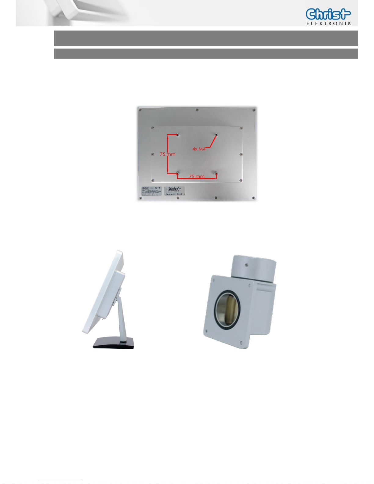
The variant Touch-it CE VESA is designed for VESA75 mount.
Suitable mounting variants are:
VESA Desk Stand Arm Mounting System VESA-
SA75
Page 10
Touch-it CE
Operating Instructions
2.2 Interfaces Connector Side
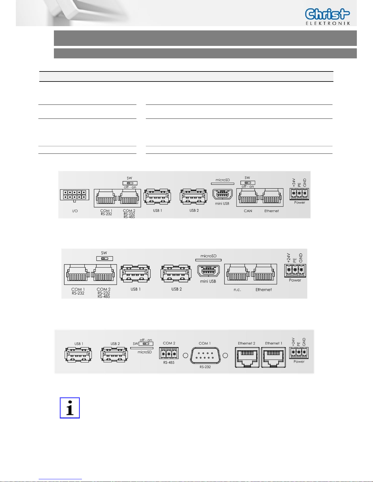
USB
2 x USB Host (Type A)
1 x Mini USB OTG (Type B) (optional)
Ethernet
1 x 100Mbit Ethernet
2 x 100Mbit Ethernet (optional)
Communication
1 x RS-232
1 x RS-232 or RS-485
1 x CAN (optional)
8 x I/Os (optional)
Mass Storage
1 x microSD up to 32GB
Power Connector
Phoenix
Connector side Touch-it CE completely
Connector side Touch-it CE standard
Connector side Touch-it CE CODESYS ready
These are the standard interface configurations. Others are possible.
For the correct interface configuration see the specific data sheet.
All interfaces are described in the chapter Interfaces.
Page 11
Touch-it CE
Operating Instructions
3 Software
Every used software in this chapter you can download from the download section:
www.christ-elektronik.de
3.1 Microsoft Windows Mobile Device Center / Active Sync
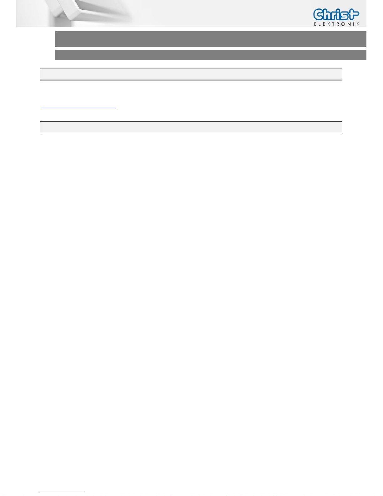
One way to establish a PC connection to the Touch-it CE is by using Windows Mobile Device
Center. For Windows XP you need instead of the Microsoft ActiveSync.
Download the correct version and install it.
Once the Windows Mobile Device Center software is properly installed, you can proceed to plug
a USB Cable (Type A – Type mini-B) between your PC USB port and the USB on the Touch-it CE.
Be sure that only the mini USB port is connected and not the shared one.
If you use the Touch-it CE Pico-ITX glass, be sure that the touchscreen is not connected to the internal USB port.
Now a connection should be established and a partnership between PC and CE Device will be
created. You can save the Registry now, so that it will remember the partnership and you'll never
be prompted again.
Windows Mobile Device Center was originally intended to be used to synchronize data (appointments, mails, etc) between a CE Device and a Desktop PC, but can also be used as a simple
file browser.
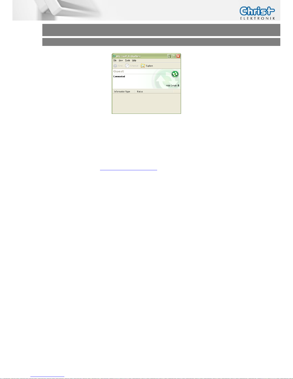
Once the Windows Mobile Device Center connection is up and running, you can open an Explorer window showing the File System of your Touch-it CE:
Page 12
Touch-it CE
Operating Instructions
You can easily drag and drop files to/from your Touch-it CE Panel now.
To show the desktop of the Touch-it CE Panel on your development PC you can start the remote
display tool CeRHost.exe on your Desktop PC.
(After Windows Mobile Device Center connection is established)
Download the program from www.christ-elektronik.de
Also, Windows Mobile Device Center can be used to install applications. Most of the Windows
CE applications you can find on the WEB have an installer that expects Windows Mobile Device
Center to be present on your system, and will use it to install the software on the CE Device.
If you want to try some third party software from the WEB, be sure to download the ARM compiled Handheld PC version. Pocket PC applications will most probably not work, because they
rely on another shell and some adaptations must be done.
Windows Mobile Device Center is also very useful for debugging.
(see chapter Software -> Compilation / Debugging)
Page 13
Touch-it CE
Operating Instructions
3.2 General Information
Microsoft® Windows® CE is an open, scalable, 32-bit operating system that integrates reliable,
real time capabilities with advanced Windows technologies. Windows CE allows you to build a
wide range of innovative, small footprint devices.
3.2.1 Exploring the different interfaces that Windows CE offers
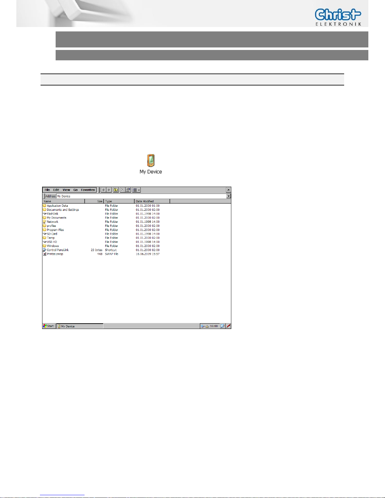
Open the "My Device" folder (upper left icon on the desktop).
This is the root folder of Windows CE. In Windows CE there are no Drive letters like in other
Windows Versions, so everything in the file system can be found under the root folder.
Almost every subfolder in the root folder resides in RAM, so if you copy/change/delete something there it will only have a temporary effect, after a power cycle all changes are reset to the
default state.
But there are some exceptions: The subfolder called "FlashDisk" is a special Flash File System
folder everything you write to this folder is persistent across power cycles.
Page 14
Touch-it CE
Operating Instructions
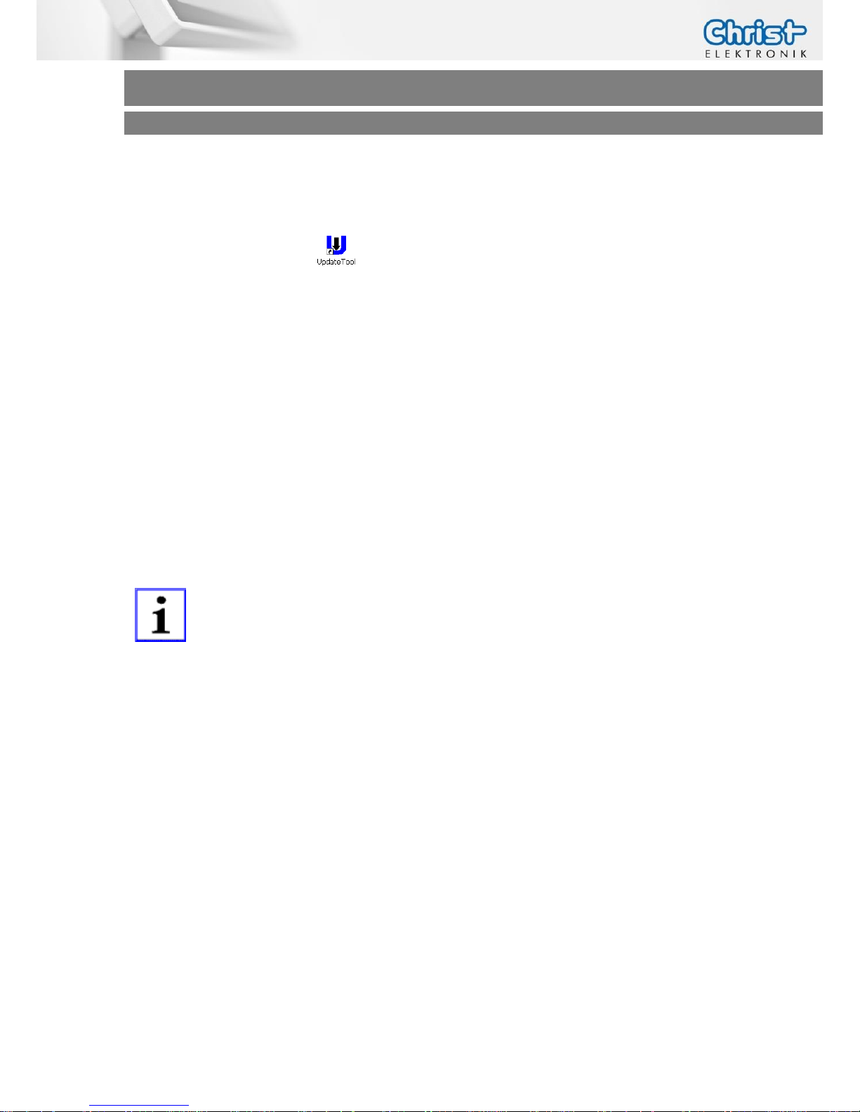
Like the RAM file system, the Windows CE registry is only stored to RAM every setting you change
will be lost after a power cycle, but there is a small utility to save the registry persistently.
Click on the Update Tool icon and then press the button Save Registry to Flash.
You will get a message informing you if the saving was successful
3.2.2 PC Connectivity over Ethernet
The installation effort to set up an Ethernet connection depends on your available network infrastructure.
If you have a DHCP server then it's very easy, just go to Start Menu->Settings->Network and Dial-
up Connections, double click on the network adapter and select "Obtain an IP address via
DHCP", confirm with OK.
If you don't have a DHCP server you can specify a static IP address to the system in this menu.
INFORMATION!
Don’t forget to make a Save Registry so the IP settings are stored persistently (See chapter Software and Registry).
Now if you have some shared files in your network you can easily access them by typing:
"\\computer name\share name" in the address bar of an explorer window.
After logging in you should be able to access the files on the network share.
Page 15
Touch-it CE
Operating Instructions
3.2.3 Compilation / Debugging
There is a C/C++ compiler available from Microsoft© (“Visual Studio 2008”, higher Versions
aren´t supported)
To start with Microsoft offers a free 90 days trial version of Visual Studio 2008.
English: http://download.microsoft.com/download/8/1/d/81d3f35e-fa03-485b-953b-
ff952e402520/VS2008ProEdition90dayTrialENUX1435622.iso
German: http://download.microsoft.com/download/c/4/a/c4a75cc0-4f7d-46ed-8ff2-
1e4cd9d0f94a/VS2008ProEdition90DayTrialDEUX1435986.iso
INFORMATION!
These two download are not provided on the www.christ-elektronik.de
homepage.
1. Install Visual Studio 2008 first following the installation instructions. If you use Windows
EC 7 Download these two Updates in addition:
“Visual Studio 2008 update for Windows Embedded Compact 7”and
“Windows Embedded Compact 7 ATL Update for Visual Studio 2008
SP1”
Download it from www.christ-elektronik.de and install it.
2. Before you can write any applications you need to install an SDK.
3. Start the Windows Mobile Device Center and connect your
Touch-it CE Panel.
(see chapter Software -> Microsoft Windows Mobile Device Center)
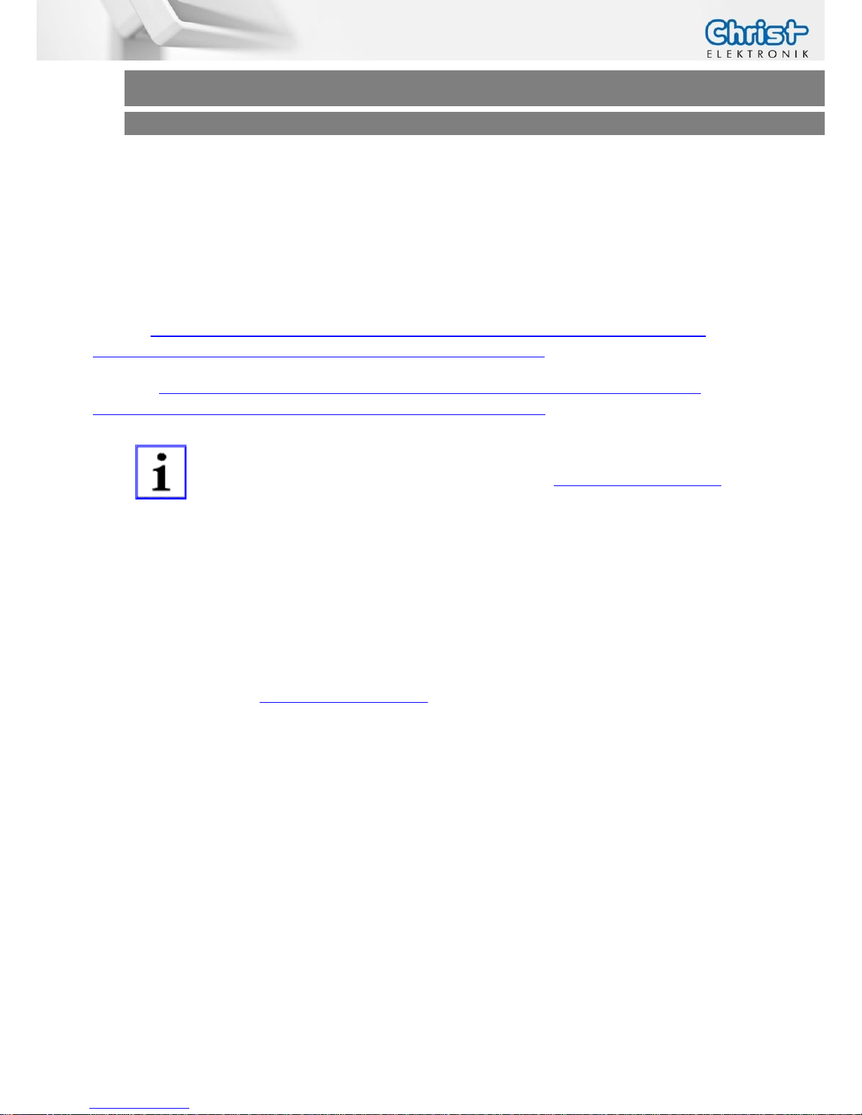
4. Start the Visual Studio 2008 and open a new project.
Select project type:
“Other Languages” -> “Visual C#” -> “Smart Device”
-> “Smart Device Project”
Page 16
Touch-it CE
Operating Instructions
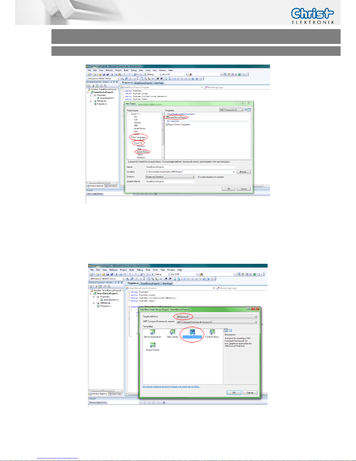
Make sure that “.NET Framework 3.5” is selected.
Accept with “OK”
Select destination platform ->”SDK2wince7”
Select template: “console application”
Accept with “OK”
Page 17
Touch-it CE
Operating Instructions
5. Write your example code:
using System;
using System.Linq;
using System.Collections.Generic;
using System.Text;
namespace SmartDeviceProject1
{
class Program
{
static void Main(string[] args)
{
Console.WriteLine("Hello, here is Touch-it CE\n");
Console.WriteLine("from Christ-Elektronik GmbH");
Console.ReadLine();
}
}
}
6. Debug your code and select the destination “SDK2wince7 ARMV7 Device”.
On the Touch-it CE Panel should appear a console application.
3.3 Flash Memory Layout
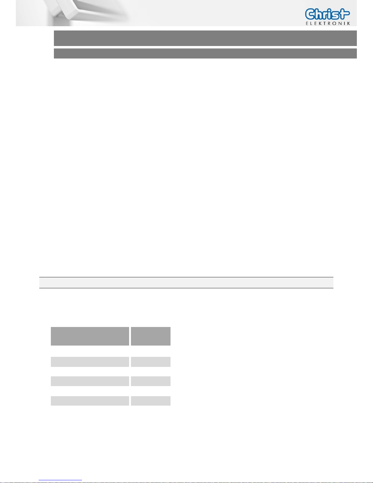
The Touch-it CE has an on board Flash memory 512 MB (Tegra T20). This Flash memory is divided as follows:
Description
Tegra
T20
Bootloader
4096 KB
ConfigBlock
3076 KB
Image
100 MB
Registry
512 KB
FileSystem (FlashDisk)
405 MB
Total
512 MB
The only permanent memory, that is available to the user, is the File System (
FlashDisk
) memory.
Page 18
Touch-it CE
Operating Instructions
3.4 Permanent Storage
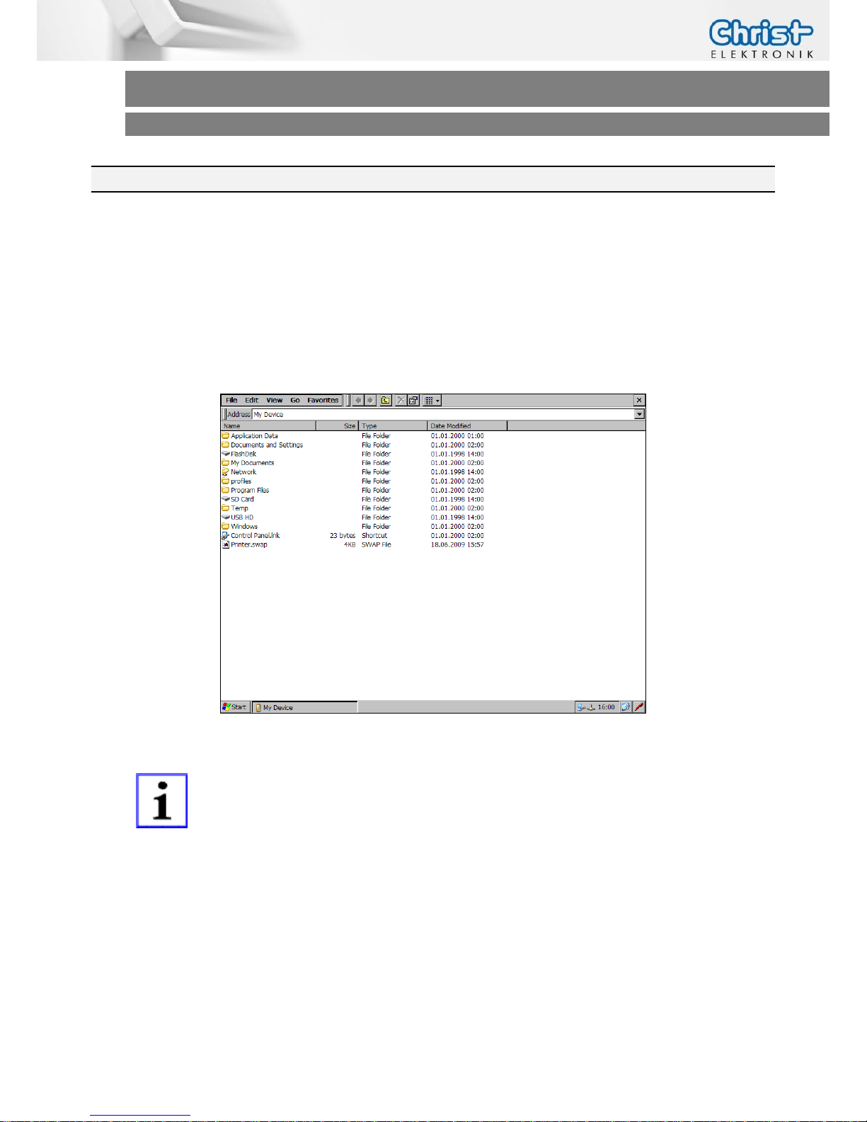
Permanent data can be stored in the Touch-it CE in three different areas:
Flash Disk
SD Card
USB HD
You can find these 3 storage areas in
My Device
as seen below:
INFORMATION!
SD Card and USB HD will only appear when a SD Card or USB Stick is
inserted.
Page 19

Touch-it CE
Operating Instructions
3.4.1 Flash Disk
The Touch-it CE comes with an on board Flash for permanent storage. You can find it in My Device under FlashDisk. Any permanent data the user wishes to store on Flash memory must be lo-
cated in the FlashDisk folder. All other places in the File System (such as the windows folder) are
in the RAM image and therefore any files copied to or modified inside these folders will be lost
after any power fail.
3.4.2 MicroSD Card
The Touch-it CE has an external microSD Card slot for additional permanent storage. microSD
storage devices will appear under \SD Card in My Device. Data stored in this device is permanent and will remain after a power fail.
3.4.3 USB HD
Permanent data can also be stored in any external USB Drive. External USB storage devices will
appear under \USB HD in My Device. Data stored in this device is permanent and will remain
after a power fail.
Page 20
Touch-it CE
Operating Instructions
3.5 Registry
Just like the RAM File System, the Windows CE registry is only stored to RAM: every setting you
change will be lost after a power cycle (these include settings such as touch calibration, taskbar
settings and display settings.
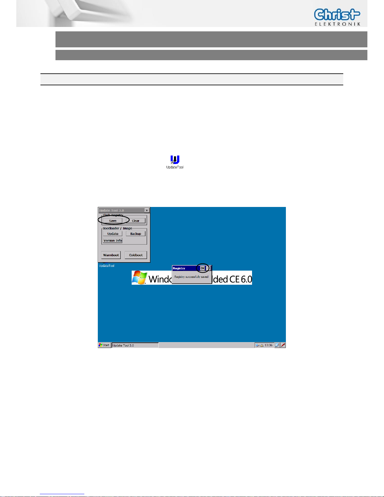
However you can save the registry changes permanently with a small utility included in the Windows CE image. In order to save the registry settings follow the steps below:
Double-click the
Update Tool
icon:
Click on the
Save
(Flash Registry) button:
Confirm the Windows dialog with OK.
Page 21

Touch-it CE
Operating Instructions
3.6 Windows CE 6.0/ EC 7 Bootloader & Image Update
The Windows CE 6.0 operating system is located in one single image file with .bin extension.
The Windows EC 7 operating system is located in one single image file with .nb0 extension. This
file is located inside the flash memory of the Touch-it CE.
This image file is loaded into RAM memory each time the Touch-it CE is powered up. Since the
*.bin / *.nb0 image file is not modified during the use of the Touch-it CE, Windows CE will always boot from the same clean image.
The only way to update the operating system is to replace the existing *.bin / *.nb0 file with a
new one. This can be done via LAN, USB, SD, memory or by a terminal connection through
COM1.
3.6.1 Image Update via external memory (USB, SD)
From Christ-Elektronik you can get the files, to make an image update. Below you find the steps
for the update.
- Unzip all the directories (AutoRun, Autoxsc, etc.) and copy to a USB Stick or microSD card
- Turn on device and close all running applications
- Plug in the storage medium (SD, USB) to the device, update is done automatically
- Wait until the Touch-it CE restarts (about 2-3 minutes)
- When the message appear: “remove the USB Stick and restart”
- Turn off the Touch-it Panel PC and remove USB Stick / microSD card afterwards
- Switch the Touch-it Panel PC on and make a Touchscreen calibration (See chapter Touch Cal-
ibration)
- Save the Registry (See chapter Software ->Registry)
Page 22

Touch-it CE
Operating Instructions
3.6.2 Image Update via terminal connection
From Christ-Elektronik you can get the files, to make an image update. Below you find the steps
for the update.
- Run a terminal with 115,2 Kbaud, 8data bits, none parity, 1 stop bit
- Connect the serial cable at the COM1 port of your Touch-it CE Panel and your PC
- Connect a mini USB cable to the Touch-it CE Panel and your PC
- Send continuous blank characters “ “ over the terminal to the Touch-it CE Panel while
the Touch-it CE Panel is booting
- Now you should see the boot loader menu
- Type in “reboot rcm”
- Go to the “DeviceManager” on your PC. A device called “APX” must appear
- Click on it and press the Update Driver button
- Browse on your computer to the “usbpc_driver_32_64” folder inside
the Tegra OS image folder and install it
- Now you can confirm the successful driver installation by verifying “NVIDIA USB Boot-
recovery driver” for Mobile devise under Universal Serial Bus controllers
- Open the Image folder and start “update_T20.bat” then enter 1 or 2 to choose your
operation system
CAUTION!
This will delete all data on the module, including registry and the flash
file system.
Once the image gets flash successfully, restart the Touch-it CE Panel.
Page 23
Touch-it CE
Operating Instructions
3.7 Running Applications at Startup (Autorun)
There is a special Launcher.exe tool that automatically starts any .exe or .lnk file found in a
\AutoRun folder on each storage medium. This can be used to autorun your application. Just
make a \AutoRun folder inside the \FlashDisk memory, put your application in it and it will run at
each start-up.
This feature also works on all removable media. You can create a \AutoRun folder on a USB Stick
or SD Card, put it in the Touch-it CE and your application will be automatically launched every
time you insert that USB Stick or SD Card.
INFORMATION!
Press the left shift button on your extern keyboard at boot time many times
to interrupt the launcher.exe. The AutoRun folder will not executed.
3.8 Adding Files to Desktop or Start Menu (AutoCopy)
\Desktop and \Start Menu are subfolders in the \Windows folder, if you add some files there
(shortcuts) they will be lost on next reboot (because the folder is only in the RAM based file system).
There is however a way to copy files from the Flash File System (permanent) to any other nonpermanent location. Just make a \AutoCopy folder in the FlashDisk folder. Any file you put in this
\AutoCopy folder will automatically be copied to the \ (root folder) at boot time (this is done by
the Launcher Tool).
So if you want to copy some files to your \Desktop folder at boot time you must copy them to:
\FlashDisk\AutoCopy\Windows\Desktop\
The AutoCopy function works also on removable media such as USB Sticks and SD Cards.
Page 24
Touch-it CE
Operating Instructions
3.9 Touch-it CE Remote Control
You are able to connect your Touch-it CE Device with your Desktop PC via LAN.
1) Your Touch-it CE Device and Desktop PC have to be connected in the same network
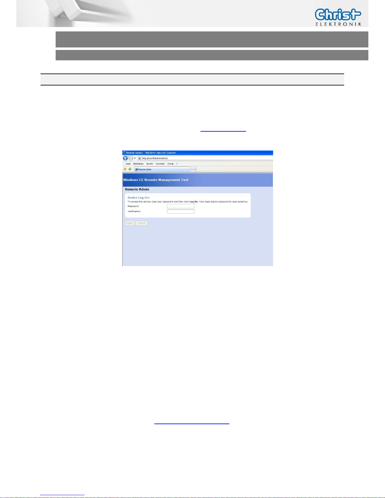
2) Open a Browser on your Desktop PC and go to http://touchit/ or type in the IP address of the
Touch-it CE Device.
3) Type in your password for the user admin (i.e. admin)
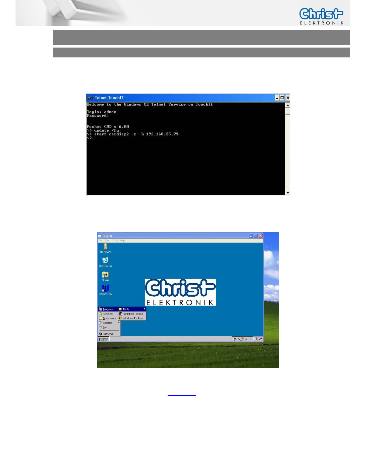
4) Start Telnet on your Desktop PC:
a) start cmd.exe
b) type “telnet”
c) type “open TouchIt”
d) Login: admin
e) Password: admin
If problems occur be sure that Telnet is activated on your Desktop PC.
5) Save the registry over Telnet
type “update /fu”
6) Start the remote display tool on your Desktop PC
->CeRHost.exe
(Download the program from www.christ-elektronik.de)
Page 25
Touch-it CE
Operating Instructions
7) Start the remote display tool on your Touch-it CE Device over Telnet
type “start cerdisp2 –c –h IP address of your Desktop PC”
8) Now you can remote control your Touch-it CE Device with the remote display tool (CeR-
Host.exe)
You´ve got access to the shared folders of the Touch-it CE Device
a) Type in your Desktop PC explorer \\TouchIt or \\ IP address
b) Type in User and password
c) i.e. open the Flash Disk folder
Page 26
Touch-it CE
Operating Instructions
4 Interfaces
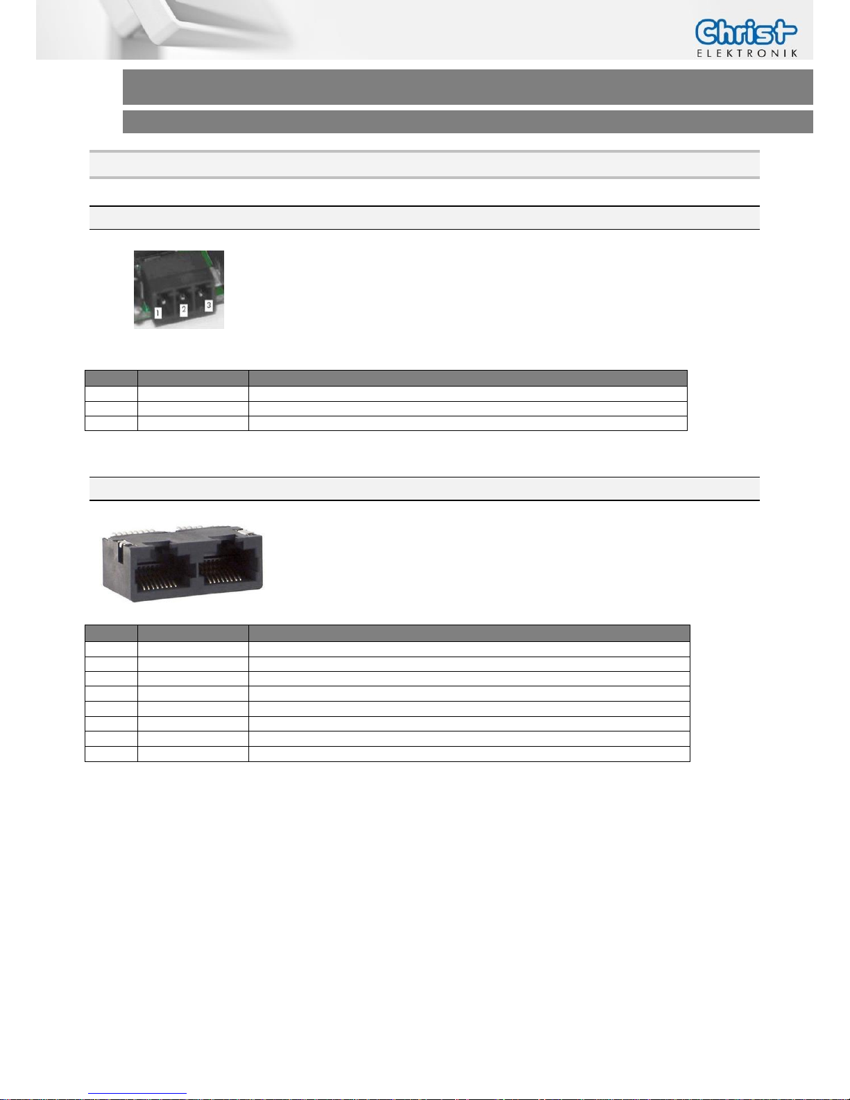
4.1 Power Supply Connector
Mating
Connector
Phoenix Connector MC 1.5/3-ST-3,5
Pin
Function
Description
1
GND
Power Supply GND
2
PE
PE
3
VCC
Power Supply VCC
4.2 Ethernet Connector
Type
10/100 Base-TX RJ45 Tab-up
Pin
Function
Description
1
ETH_TX_P
Transmit Data+
2
ETH_TX_N
Transmit Data -
3
ETH_RX_P
Receive Data +
4
PE / V+
V+ (only PoE version)
5
PE / V+
V+ (only PoE version)
6
ETH_RX_N
Receive Data -
7
PE / V-
V- (only PoE version)
8
PE / V-
V- (only PoE version)
Page 27
Touch-it CE
Operating Instructions
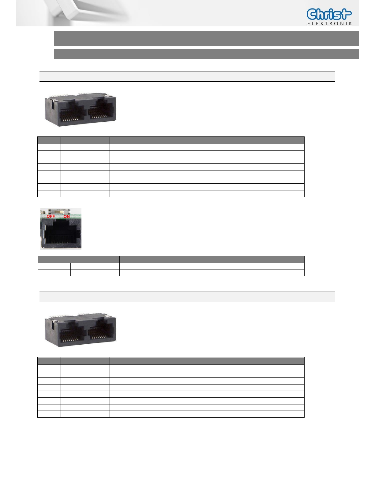
4.3 CAN Connector
Type
RJ45 Tab-up
Pin
Function
Description
1
CAN-High
Can High Signal
2
CAN-Low
Can Low Signal
3
CAN-GND
Can Ground Signal
4
n.c.
5 n.c.
6 n.c.
7 n.c.
8
n.c.
The switch above the CAN Connector enables the termination
resistor (120Ω) between the CAN-High and CAN-Low signals.
4.4 COM1 (RS-232)
Type
RJ45 Tab-up
Pin
Function
Description
1
GND
Ground
2
GND
Ground
3
n.c.
4 TxD
Transmit Data
5
RxD
Receive Data
6
n.c.
7 RTS
Request to Send
8
CTS
Clear to Send
Position SW2
Description
OFF
„left“
CAN Termination Off
ON
„right“
CAN Termination On
Page 28
Touch-it CE
Operating Instructions
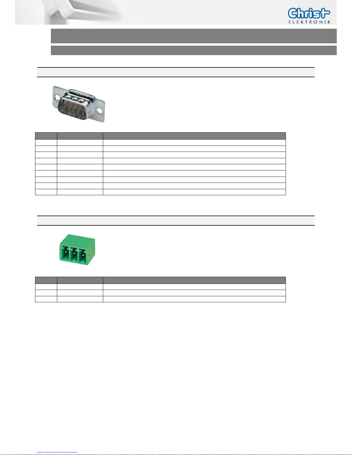
4.5 COM1 (RS-232, Touch-it CE Codesys)
Type
D-SUB ST 09
Pin
Function
Description
1
n.c.
2
RxD
Receive Data
3
TxD
Transmit Data
4
n.c.
5 GND
Ground
6
n.c.
7 RTS
Request to Send
8
CTS
Clear to Send
9
n.c.
4.6 COM2 (RS-485, Touch-it CE Codesys)
Type
MC 1,5/ 3-G-3,81
Pin
Function
Description
1
GND
Ground
2
B(-)
RS-485 Data-
3
A(+)
RS-485 Data+
Page 29
Touch-it CE
Operating Instructions
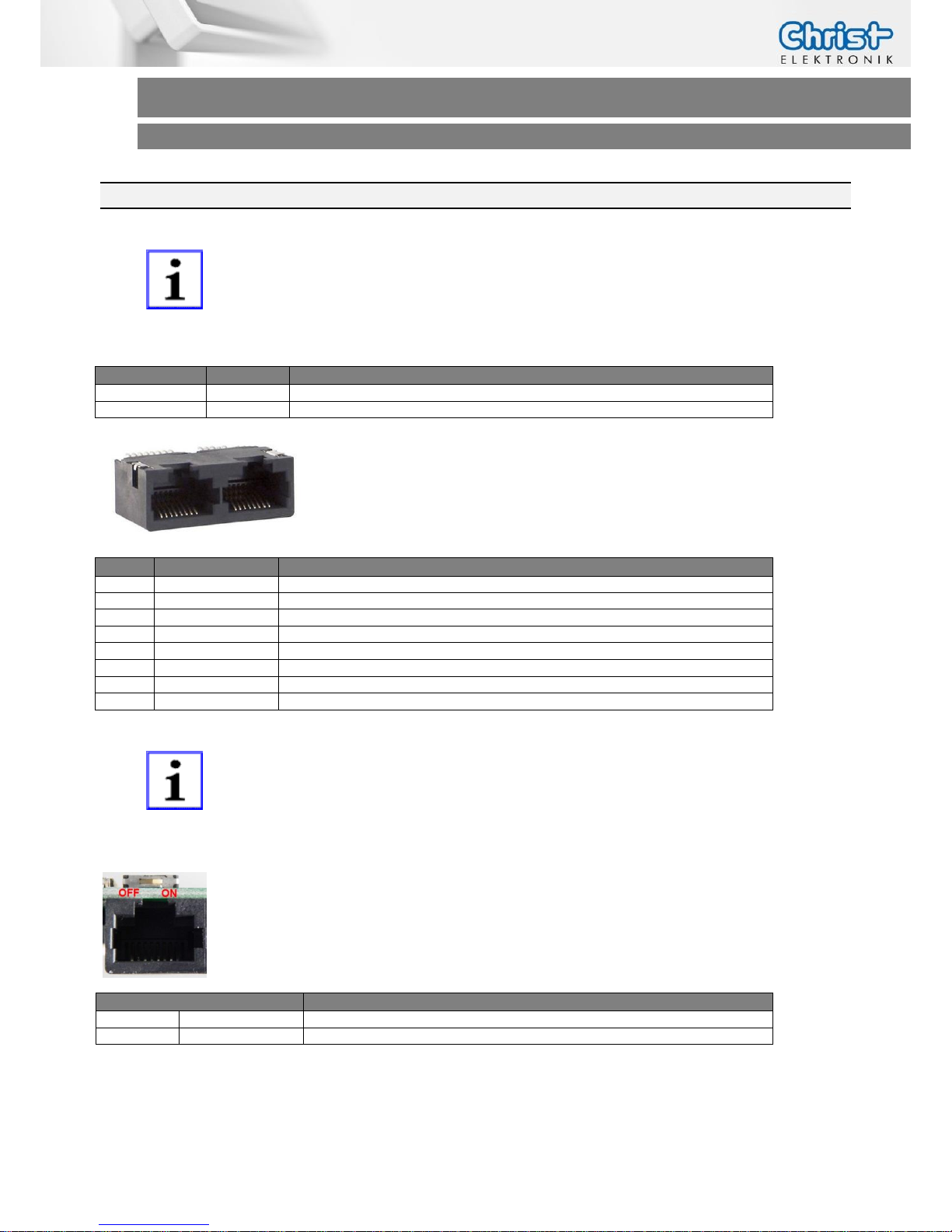
4.7 COM2 (RS-232 or RS-485)
INFORMATION!
The interface COM2 can be used as EIA-485 as well as EIA-232 over
software settings.
The following GPIOs must be set with Tegra 2 CPU:
Function
GPIO_C6
GPIO_C1
RS-232 Signals
Low
Low
RS-485 Signals
High
Low
Type
RJ45 Tab-up
Pin
Function
Description
1
GND
Ground
2
GND
Ground
3
A(+)
RS-485 Data+
4
TxD
RS-232 Transmit Data
5
RxD
RS-232 Receive Data
6
B(-)
RS-485 Data-
7
n.c
8 n.c.
INFORMATION!
For writing via RS-485 the GPIO_K7(Tegra T20) must be set “High” and for
reading the GPIO must be set “Low”.
The switch above the COM2 Connector enables the termination
resistor (120Ω) between the A(+) and B(-) signals of the RS-485.
Position SW2
Description
OFF
„left“
RS-485 Termination Off
ON
„right“
RS-485 Termination On
Page 30
Touch-it CE
Operating Instructions
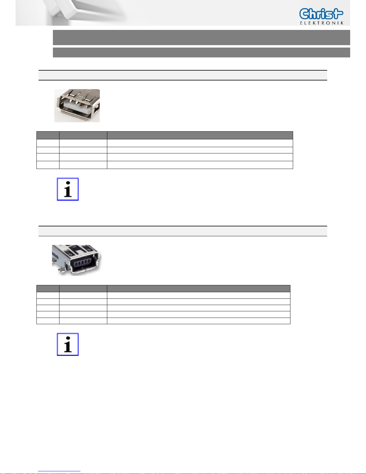
4.8 USB Type A
Type
WR-COM USB Type A
Pin
Function
Description
1
VBUS
USB VCC
2
D+
USB Data+
3
D-
USB Data-
4
GND
USB GND
INFORMATION!
The USB Type A (Port2) and the USB Mini-B are shared ports. It’s only possible to use one of them simultaneously.
4.9 USB Mini Type B Extern
Type
MINI USB SMT TYPE AB 5 CONTACTS
Pin
Function
Description
1
VBUS
USB VCC
2
D+
USB Data+
3
D-
USB Data-
4
N.C
5 GND
USB GND
INFORMATION!
The USB Type A (Port2) and the USB Mini-B are shared ports. It’s only possible to use one of them simultaneously.
Page 31
Touch-it CE
Operating Instructions
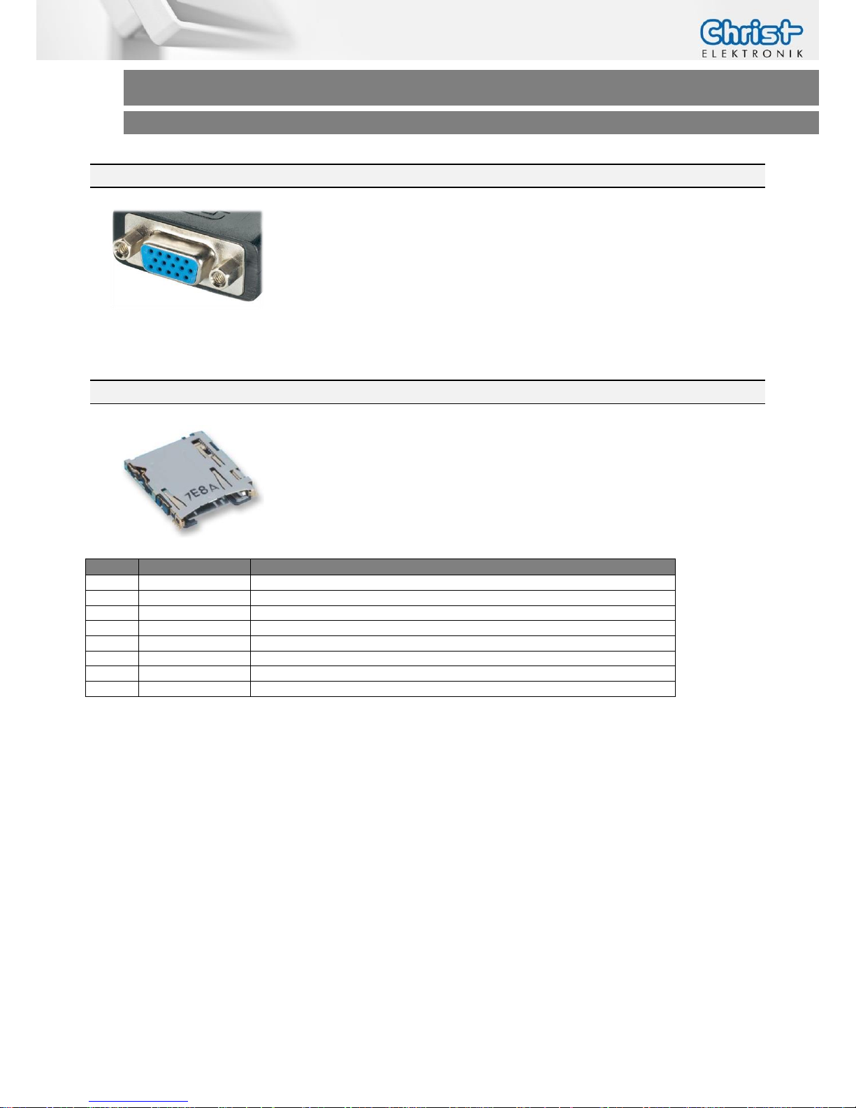
4.10 Connector
Type
Mini Sub-D BU HD15
The VGA interface is equal with the standard VGA pin assignment.
4.11 MircoSD
Type
DM3AT-SF-PEJ
Pin
Function
Description
1
D2
SD/MMC Data 2
2
D3/CD
SD/MMC Data 3
3
CMD
SD/MMC Command
4
+3.3V
5 CLK
SD/MMC Clock
6
GND
7 D0
SD/MMC Data 0
8
D1
SD/MMC Data 1
Page 32
Touch-it CE
Operating Instructions
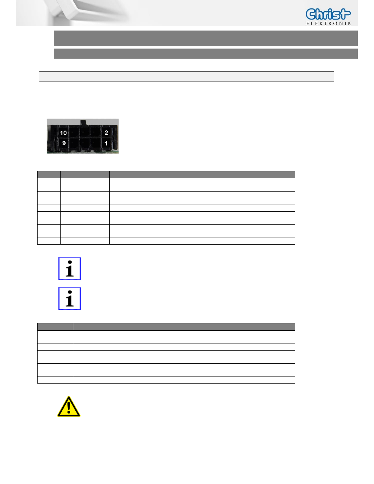
4.12 I/O Connector
The Touch-it CE provides 4 digital outputs and 4 digital inputs with an external power supply as
standard.
Mating
Connector
Würth WR-MPC3, 10 pol
Pin
Function
Description
1
+24VDC
VCC 2 GND
Ground
3
In_4
Input 4
4
Out_4V
Output 4
5
In_3
Input 3
6
Out_3
Output 3
7
In_2
Input 2
8
Out_2
Output 2
9
In_1
Input 1
10
Out_1
Output 1
INFORMATION!
The digital input and output signals are isolated from the internal signals.
Therefore external power of +24V DC and external GND are needed.
INFORMATION!
For controlling the digital inputs and outputs are following GPIO used:
Function
GPIO Tegra 2
IN_1
GPIO_C7
IN_2
GPIO_B6
IN_3
GPIO_BB2
IN_4
GPIO_B7
OUT_1
GPIO_T2
OUT_2
GPIO_T1
OUT_3
GPIO_T3
OUT_4
GPIO_L6
ATTENTION!
Load current per output max. 0.5 A!
Page 33
Touch-it CE
Operating Instructions
5 Pointers
5.1 Used symbols
Symbols
The following symbols are used in this instruction manual:
DANGER!
Denotes a direct threat of danger. Not observing this pointer may be life
threatening or lead to serious injuries.
CAUTION!
Denotes a possibly dangerous situation. Not observing this pointer can
cause minor injuries or lead to material damages.
INFORMATION!
Denotes application pointers and other useful information.
5.2 General pointers
INFORMATION!
This device was manufactured according to DIN EN ISO 9001 and left the
factory in a perfect state.
In order to maintain this state and to assure the safe operation, the user
must consider the pointers and warning remarks, which are contained in
this instruction manual.
INFORMATION!
Displays may contain defect pixels from the manufacturing process.
These lacks aren´t reasons for a warranty.
Page 34
Touch-it CE
Operating Instructions
5.3 Safety pointers
DANGER!
In the case of damage of the device, shut it down and disconnect it immediately from the supply voltage.
Disconnect every connection line and send it back to Christ-Elektronik
GmbH.
DANGER!
Avoid any penetration of liquid or dust.
Do not expose the device to humidity for a long time!
Intended Use
These products are not designed, developed and produced for use, which
pose fatal risks and dangers that may cause death, injuries, serious physical impairments or other loss, if no exceptional security measures are ensured. Thus there are limitations for use in the monitoring of nuclear reactions in nuclear power plants, flight control systems, air traffic control, in the
control of mass transportation, medical life support systems and control of
weapon systems.
CAUTION!
If the device is used for other purposes or incorrectly operated,
Christ-Elektronik GmbH will not hold damages liable.
Do not operate the touch-sensitive surface of the screen with any abrasive
or sharp-edged objects.
Protect the Touch-it Panel PC against caustic chemicals and long solar
radiation.
Page 35
Touch-it CE
Operating Instructions
CAUTION!
Never cover the Touch-it Panel PC completely or build it in a small closed
and unvented housing.
CAUTION!
This is a Class A product. In a domestic environment this product may
cause radio interference, in which case the user may be required to take
adequate measures.
INFORMATION!
Please check immediately:
Is the device damaged or is any equipment missing?
(See chapter Commissioning)
In the case of defect please inform us immediately.
5.4 Maintenance plan
INFORMATION!
Only the manufacturer (Christ-Elektronik GmbH) is allowed to replace the
internal lithium battery.
The calibration of the analog resistive touch may be required from time
to time.
5.5 Repairs
DANGER!
Only the qualified staffs are allowed to carry out the repairs. The incorrect
repair may lead to serious danger for the user.
Page 36
Touch-it CE
Operating Instructions
5.6 Cleaning
DANGER!
Disconnect the Touch-it Panel PC from the supply voltage before cleaning.
CAUTION!
Do not clean the touch-sensitive surface of the monitor with detergents containing solvent or acid.
INFORMATION!
Use a humid and soft cloth with gentle soapsuds to clean.
Page 37
Touch-it CE
Operating Instructions
Contact
Christ – Elektronik GmbH
Alpenstraße 34
D-87700 Memmingen
Tel. +49 (0)8331/8371-0
http://www.christ-elektronik.de
More Information
Learn more about
Christ – Elektronik Touch-it
solutions, please contact your Christ
– Elektronik GmbH sales representative or visit our website.
http://www.christ-elektronik.de
Contact
Christ – Elektronik GmbH
Alpenstraße 34
D-87700 Memmingen
Tel. +49 (0)8331/8371-0
Website:
http://www.christ-elektronik.de
Copyrights
All rights reserved, including intellectual property rights. Changes to
technical data reserved. Delivery
subject to availability
Copyright © Christ – Elektronik
GmbH
Disclaimer
Technical data are subject to modification and delivery subject to
availability. Any liability that the
data and illustrations are complete,
actual or correct is excluded. Designations may be trademarks and/or
copyrights of the respective manufacturer, the use of which by third
parties for their own purposes may
infringe the rights of such owner
 Loading...