

Page 1
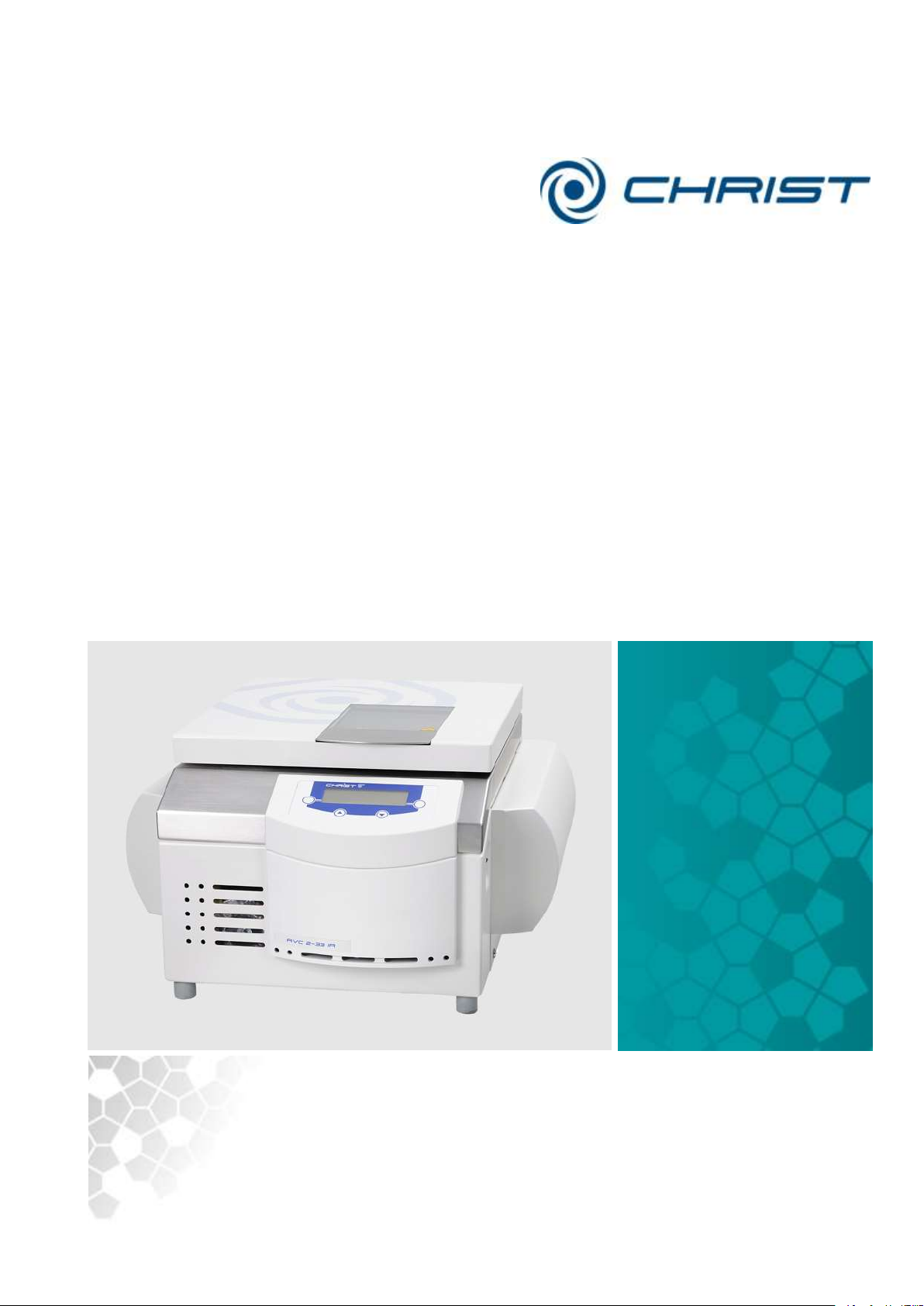
Translation of the original operating manual
sb
Rev. 3.3 of 03/07/2016
RVC 2-33 CDplus; ;with infrared heating
Version 08/2009
RVC 2-33 CDplus
with infrared heating
part no. 100244
Rotational Vacuum
Concentrator
Operating Manual
Please retain for later use!
Page 2

Rotational Vacuum Concentrator RVC 2-33 CDplus
with infrared heating
2 / 88
Version 08/2009, Rev. 3.3 of 03/07/2016 • sb
Translation of the original operating manual
Page 3

Rotational Vacuum Concentrator RVC 2-33 CDplus
with infrared heating
Version 08/2009, Rev. 3.3 of 03/07/2016 • sb
3 / 88
Translation of the original operating manual
In case of inquiries, please state the following numbers:
Order number:
Serial number:
© Copyright by
Martin Christ Gefriertrocknungsanlagen GmbH
An der Unteren Söse 50
37520 Osterode am Harz
Germany
Tel.: +49 (0) 5522 / 5007-0
Fax: +49 (0) 5522 / 5007-12
Web: www.martinchrist.de
E-mail: [email protected]
Page 4

Rotational Vacuum Concentrator RVC 2-33 CDplus
with infrared heating
4 / 88
Version 08/2009, Rev. 3.3 of 03/07/2016 • sb
Translation of the original operating manual
Page 5

Rotational Vacuum Concentrator RVC 2-33 CDplus
with infrared heating
Table of contents
Version 08/2009, Rev. 3.3 of 03/07/2016 • sb
5 / 88
Translation of the original operating manual
1 General information ............................................................................................................. 9
1.1 Importance of the operating manual .................................................................................. 9
1.2 Intended use ..................................................................................................................... 9
1.3 Warranty and liability......................................................................................................... 9
1.4 Copyright ........................................................................................................................ 10
1.5 Explanation of symbols ................................................................ ................................... 10
1.6 Standards and regulations .............................................................................................. 10
1.7 Scope of supply .............................................................................................................. 10
2 Layout and mode of operation .......................................................................................... 11
2.1 Layout of the RVC .......................................................................................................... 11
2.1.1 Functional and operating elements ............................................................................ 11
2.1.2 Name plate ................................................................................................................ 12
2.2 Mode of operation ........................................................................................................... 13
2.2.1 Principle of the rotational vacuum concentration ........................................................ 13
2.2.1.1 Advantages of the rotational vacuum concentration ........................................... 14
2.2.1.2 Examples of use ................................................................................................ 15
3 Safety .................................................................................................................................. 16
3.1 Marking of the unit .......................................................................................................... 16
3.2 Explanation of the symbols and notes ............................................................................. 17
3.3 Responsibility of the operator .......................................................................................... 18
3.4 Operating personnel ....................................................................................................... 18
3.5 Informal safety instructions ............................................................................................. 18
3.6 Safety instructions .......................................................................................................... 19
3.6.1 Electrical safety ......................................................................................................... 19
3.6.2 Mechanical safety ...................................................................................................... 19
3.6.3 Fire prevention ................................ ................................................................ ........... 20
3.6.4 Thermal safety ........................................................................................................... 20
3.6.5 Chemical and biological safety .................................................................................. 20
3.6.6 Safety instructions for evaporation ............................................................................. 21
3.7 Safety devices ................................ ................................................................................ 21
3.7.1 Lid lock device ........................................................................................................... 21
3.7.2 System check ............................................................................................................ 21
3.7.3 Power failure safety ................................................................................................... 21
3.7.4 Earth conductor check ............................................................................................... 21
3.8 Procedures in the event of hazards and accidents .......................................................... 22
3.9 Remaining hazards ......................................................................................................... 22
4 Storage and transport ....................................................................................................... 23
4.1 Storage conditions .......................................................................................................... 23
4.2 Dimensions and weight ................................................................................................... 23
4.3 Packaging ....................................................................................................................... 23
4.4 Transport safety device ................................................................................................... 24
4.5 On-site transport ................................................................ ............................................. 24
Page 6

Rotational Vacuum Concentrator RVC 2-33 CDplus
with infrared heating
Table of contents
6 / 88
Version 08/2009, Rev. 3.3 of 03/07/2016 • sb
Translation of the original operating manual
5 Set-up and connection ...................................................................................................... 25
5.1 Installation site ................................................................................................................ 25
5.2 Power supply .................................................................................................................. 25
5.2.1 Connection ................................................................................................................ 25
5.2.2 Customer-provided fuses ........................................................................................... 25
5.3 Aeration and micro injection valve (Valve block) ............................................................. 26
5.4 Vacuum connections....................................................................................................... 27
5.5 Option: Pressure control valve and vacuum sensor ........................................................ 28
5.6 Connection of a vacuum pump and/or a cooling trap ...................................................... 29
5.6.1 Withdrawal of the vapours by a vacuum pump ........................................................... 29
5.6.2 Condensation of the vapours upstream of the vacuum pump in a cooling trap ........... 30
5.6.2.1 Option: Remote control of the cooling trap via RVC ........................................... 31
6 Operation ............................................................................................................................ 32
6.1 Initial start-up .................................................................................................................. 32
6.2 Switching the RVC on ..................................................................................................... 32
6.3 Opening and closing the lid ............................................................................................. 32
6.4 Installation of rotors and accessories .............................................................................. 33
6.4.1 Installation of angle rotors .......................................................................................... 33
6.4.2 Installation of swing-out rotors ................................................................................... 34
6.4.3 Installation of accessories .......................................................................................... 34
6.4.3.1 Tubes ................................ ................................................................ ................. 35
6.4.3.2 Rotor blocks ....................................................................................................... 36
6.4.3.3 Buckets ................................................................................................ .............. 36
6.5 CDplus control system ................................................................................................ .... 38
6.5.1 User interface ............................................................................................................ 38
6.5.2 Mode ......................................................................................................................... 41
6.5.3 Main menu ................................................................................................................. 43
6.5.3.1 Changing the set values for the manual mode ................................................... 43
6.5.3.2 Program administration ................................ ...................................................... 45
6.5.3.3 Special functions ................................................................................................ 48
6.5.3.4 Process and equipment information ................................................................... 49
6.5.3.5 Options .............................................................................................................. 50
7 Malfunctions and error correction .................................................................................... 53
7.1 General malfunctions ...................................................................................................... 53
7.1.1 Error messages ................................ ................................................................ ......... 53
7.1.2 Process messages .................................................................................................... 54
7.1.3 System messages ..................................................................................................... 55
7.1.4 Emergency lid release ............................................................................................... 55
7.1.5 Small flange connections ........................................................................................... 57
7.2 Service contact ............................................................................................................... 58
Page 7

Rotational Vacuum Concentrator RVC 2-33 CDplus
with infrared heating
Table of contents
Version 08/2009, Rev. 3.3 of 03/07/2016 • sb
7 / 88
Translation of the original operating manual
8 Maintenance and service ................................................................................................... 59
8.1 Maintenance ................................................................................................................... 59
8.1.1 Rotational vacuum concentrator ................................................................................ 59
8.1.2 Rotor chamber ........................................................................................................... 60
8.1.3 Accessories ............................................................................................................... 64
8.1.3.1 Aluminium accessories ...................................................................................... 65
8.1.4 Glass breakage ......................................................................................................... 65
8.2 Disinfection of the rotor chamber and accessories .......................................................... 66
8.3 Autoclaving ..................................................................................................................... 66
8.4 Service ........................................................................................................................... 67
8.5 Return of defective parts ................................................................................................. 67
9 Disposal .............................................................................................................................. 69
9.1 Disposal of the RVC........................................................................................................ 69
9.2 Disposal of the packaging ............................................................................................... 69
10 Technical data .................................................................................................................... 70
10.1 Ambient conditions ......................................................................................................... 71
10.2 Technical documentation ................................................................................................ 71
11 Appendix ............................................................................................................................ 72
11.1 Mathematical relations ................................................................................................ .... 72
11.2 Rotor program................................................................................................................. 73
11.3 Overview of evaporation times ........................................................................................ 75
11.4 Brief operating instructions ............................................................................................. 77
11.5 EC declaration of conformity ........................................................................................... 79
11.6 Declaration of conformity – China RoHS 2 ...................................................................... 81
12 Glossary ............................................................................................................................. 83
13 Index ................................................................................................................................... 85
Page 8

Rotational Vacuum Concentrator RVC 2-33 CDplus
with infrared heating
Table of contents
8 / 88
Version 08/2009, Rev. 3.3 of 03/07/2016 • sb
Translation of the original operating manual
Page 9

Rotational Vacuum Concentrator RVC 2-33 CDplus
with infrared heating
1 General information
Version 08/2009, Rev. 3.3 of 03/07/2016 • sb
9 / 88
Translation of the original operating manual
1 General information
1.1 Importance of the operating manual
A fundamental requirement for the safe and trouble-free operation of the
unit is to be familiar with the fundamental safety instructions and all
possible hazards.
The operating manual includes important information concerning the safe
operation of the rotational vacuum concentrator (RVC).
This operating manual, and in particular the notes on safety and hazards,
must be observed by all persons operating the unit.
In addition, the local rules and regulations for the prevention of accidents
must be complied with.
1.2 Intended use
CHRIST rotational vacuum concentrators are solely intended for
evaporation under rotation, e.g. for the following tasks:
• concentration of DNA/RNA, proteins etc.
• preparation of samples for HPLC/thin layer chromatography, gas
chromatography, mass-spectronomy
• isolation and synthesis of organic substances
• high-throughput-screening (HTS)
• general in-lab evaporation.
Any other use beyond this area of application is regarded as improper use.
Martin Christ Gefriertrocknungsanlagen GmbH cannot be held liable for any
damage resulting from such improper use.
The intended use also includes:
• observation of all the notes and instructions included in the operating
manual
• compliance with the inspection and maintenance instructions
• prohibition of any type of extensions to, or conversions of, the unit.
1.3 Warranty and liability
The warranty and liability are subject to our "General Terms and
Conditions" that were distributed to the operator upon the conclusion of the
contract.
Warranty and liability claims are excluded if they are due to one or several
of the following reasons:
• improper use
• non-compliance with the safety instructions and hazard warnings in the
• improper installation, start-up, operation, and maintenance of the RVC.
operating manual
Page 10

Rotational Vacuum Concentrator RVC 2-33 CDplus
with infrared heating
1 General information
10 / 88
Version 08/2009, Rev. 3.3 of 03/07/2016 • sb
Translation of the original operating manual
1.4 Copyright
The copyright concerning the operating manual remains with Martin Christ
Gefriertrocknungsanlagen GmbH.
The operating manual is solely intended for the operator and their
personnel. It includes instructions and information that may not be
• duplicated,
• distributed, or
• communicated in any other way neither in full nor in parts.
Non-compliance may be prosecuted under criminal law.
1.5 Explanation of symbols
In this operating manual, the specialist terms that are explained in the
glossary (see chapter 12 - "Glossary") are marked by an arrow and printed
in italics (e.g. safety pressure).
1.6 Standards and regulations
EC-Declaration of conformity (see appendix)
1.7 Scope of supply
The scope of supply comprises:
• 1 hexagon socket wrench, size 5
• 1 L-key Torx® TX15
• 1 screwdriver Torx® TX8
• 1 operating manual
Accessories and commissioning
According to your order, our order confirmation, and our delivery note.
Page 11
Rotational Vacuum Concentrator RVC 2-33 CDplus
with infrared heating
2 Layout and mode of operation
Version 08/2009, Rev. 3.3 of 03/07/2016 • sb
11 / 88
Translation of the original operating manual
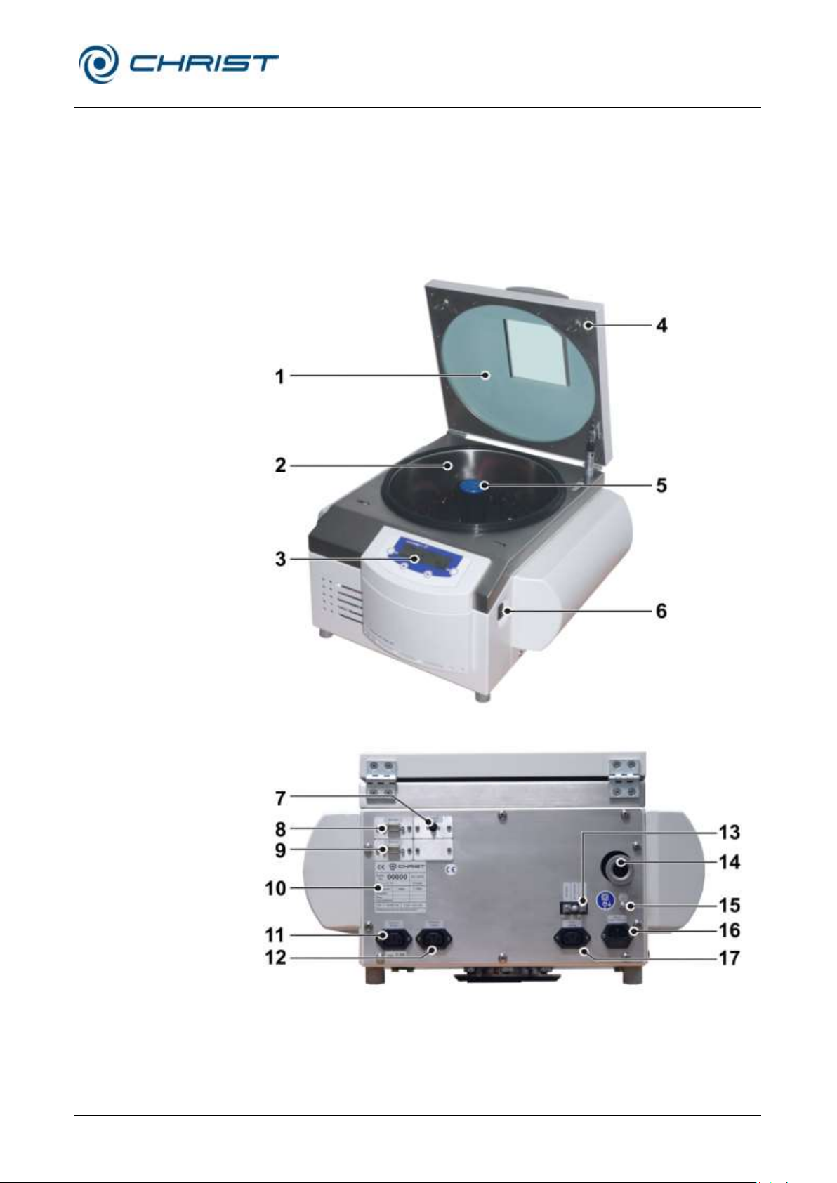
1 Lid
2 Rotor chamber
3 Control panel (see chapter
6.5.1 - "User interface")
4 Lid lock device
5 Rotor shaft
6 Mains power switch
7 Electrical vacuum sensor
connection
8 Option: Serial Interface RS
232
9 Option: Serial Interface
Remote
10 Name plate (see chapter
2.1.2 - "Name plate")
11 Power supply connection
of the vacuum pump
12 Power supply connection
of the pressure control
valve
13 Valve block (see chapter
5.3 - "Aeration and micro
injection valve (Valve
block)")
14 Vacuum connection
15 Equipotential bonding
screw
16 Mains connection and
mains fuse protection
17 Power supply connection
of the stop valve
Fig. 1: Total view of the RVC
Fig. 1: Rear view of the RVC
2 Layout and mode of operation
2.1 Layout of the RVC
2.1.1 Functional and operating elements
Page 12
Rotational Vacuum Concentrator RVC 2-33 CDplus
with infrared heating
2 Layout and mode of operation
12 / 88
Version 08/2009, Rev. 3.3 of 03/07/2016 • sb
Translation of the original operating manual
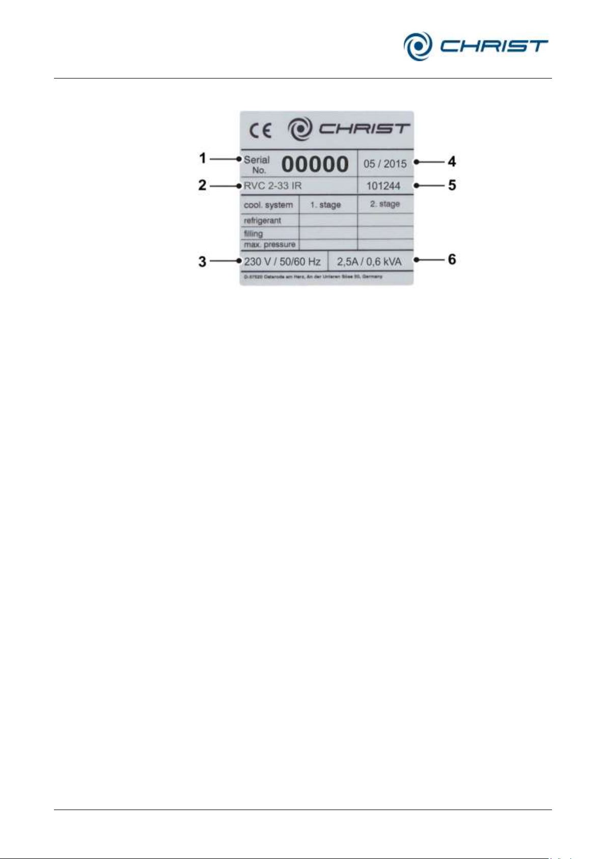
1 Serial number
2 Type
3 Nominal voltage
4 Year of manufacture
(month/year)
5 Part number
6 Rated current /
apparent power
Fig. 2: Example of a name plate
2.1.2 Name plate
Page 13
Rotational Vacuum Concentrator RVC 2-33 CDplus
with infrared heating
2 Layout and mode of operation
Version 08/2009, Rev. 3.3 of 03/07/2016 • sb
13 / 88
Translation of the original operating manual
2.2 Mode of operation
2.2.1 Principle of the rotational vacuum concentration
This method is used for the particularly quick and gentle evaporation,
drying, purification, and concentration of samples.
Rotational vacuum concentration is an alternative to rotary evaporators that
use high temperatures and operate nearly at normal pressure. Because of
the vacuum, the sample boils at low temperatures, and water as well as
organic solvents can be evaporated in a particularly gentle manner. Due to
the fact that the sample rotates like in a centrifuge, the Boiling retardation
is prevented so efficiently that low pressure can be used. As a result,
temperature-sensitive samples can be concentrated by evaporation without
being damaged.
The solvent can be collected in a cooling trap and disposed of immediately
if desired.
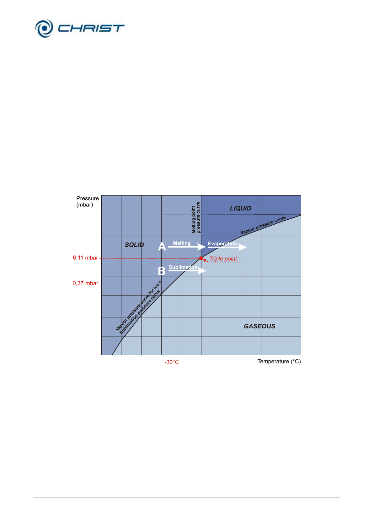
Fig. 3: Vapour pressure curve for ice and water
Page 14
Rotational Vacuum Concentrator RVC 2-33 CDplus
with infrared heating
2 Layout and mode of operation
14 / 88
Version 08/2009, Rev. 3.3 of 03/07/2016 • sb
Translation of the original operating manual
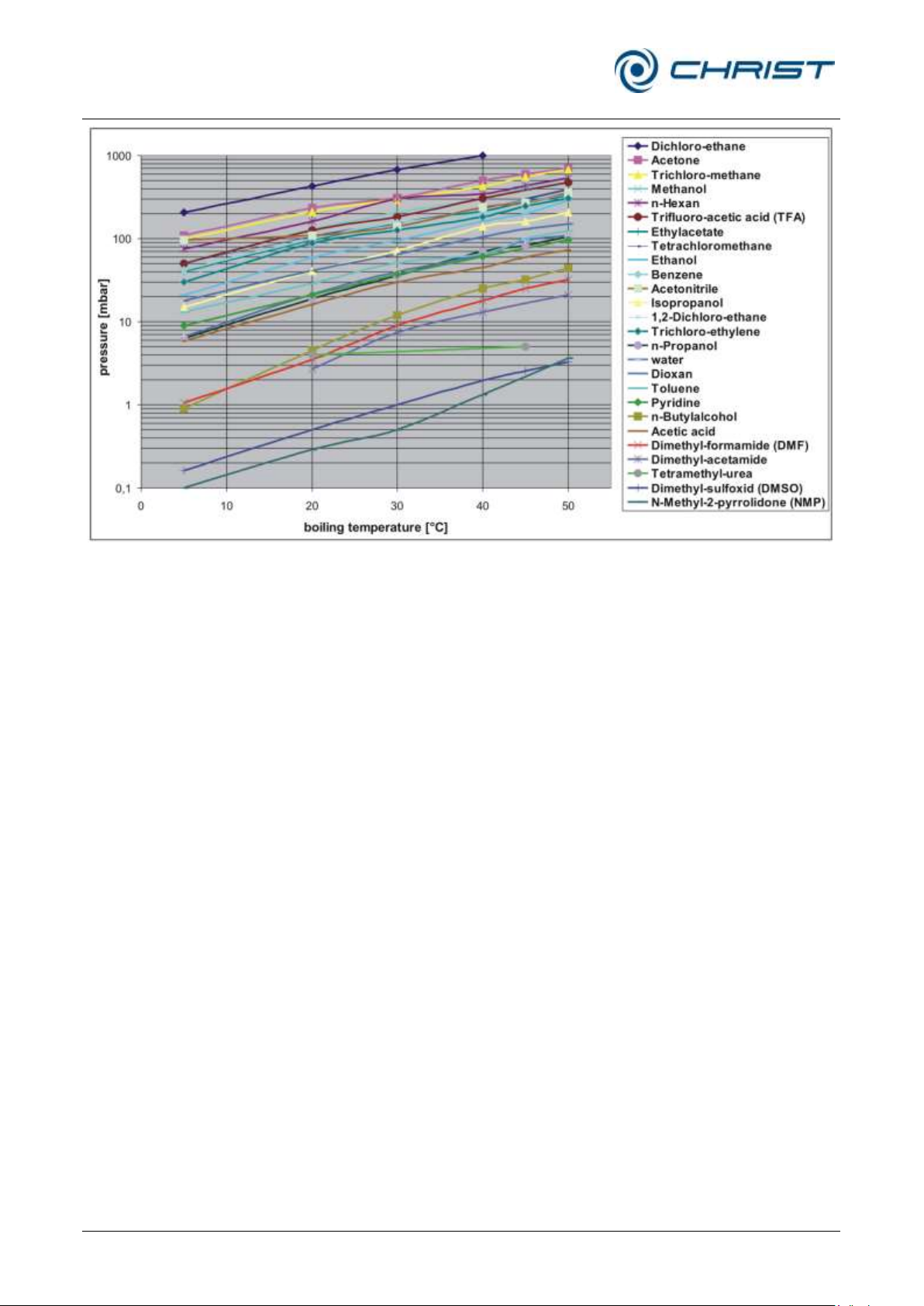
Fig. 4: Vapour pressure curves of commonly used organic solvents
2.2.1.1 Advantages of the rotational vacuum concentration
• No foaming of the samples, minimum loss.
• Several samples can be dried simultaneously.
• Concentration of the sample on the bottom of the vessel. This is
particularly advantageous for small volumes or dilute solutions.
• Suitable for drying aqueous and solvent-containing samples.
• For volumes < 1 ml up to > 3 l.
• Reproducible drying processes thanks to controlled process
parameters, such as the rotor chamber temperature (energy input for
the evaporation) and vacuum (up to the automatic adjustment of the
optimum operating pressure – depending on the pump systems).
• Easy and safe solvent recovery.
Page 15

Rotational Vacuum Concentrator RVC 2-33 CDplus
with infrared heating
2 Layout and mode of operation
Version 08/2009, Rev. 3.3 of 03/07/2016 • sb
15 / 88
Translation of the original operating manual
2.2.1.2 Examples of use
• DNA/RNA (mainly water, ethanol, or methanol as solvent)
• Oligo-synthesis, peptides
• PCR (polymer chain reaction)
• HPLC (mainly water/acetonitrile as solvent)
• Isolation/synthesis of organic substances
• Storage and handling of substances (substance libraries)
• Combinational chemistry
• High-throughput-screening (HTS)
• Analysis of food and environmental samples, toxicology
• Forensic applications
• General laboratory evaporation
Page 16
Rotational Vacuum Concentrator RVC 2-33 CDplus
with infrared heating
3 Safety
16 / 88
Version 08/2009, Rev. 3.3 of 03/07/2016 • sb
Translation of the original operating manual
Dangerous voltage
I
On (Power)
Hot surface
0
Off (Power)
Caution! Risk of bruising
Name plate (see chapter
2.1.2 - "Name plate")
Attention, consult the
operating manual
CE mark in compliance
with the directive
2006/42/EC
Protective earth (ground)
Unplug the mains plug
Earth (ground)
China RoHS 2 mark
(only for China)
Arrow indicating the
direction of rotation
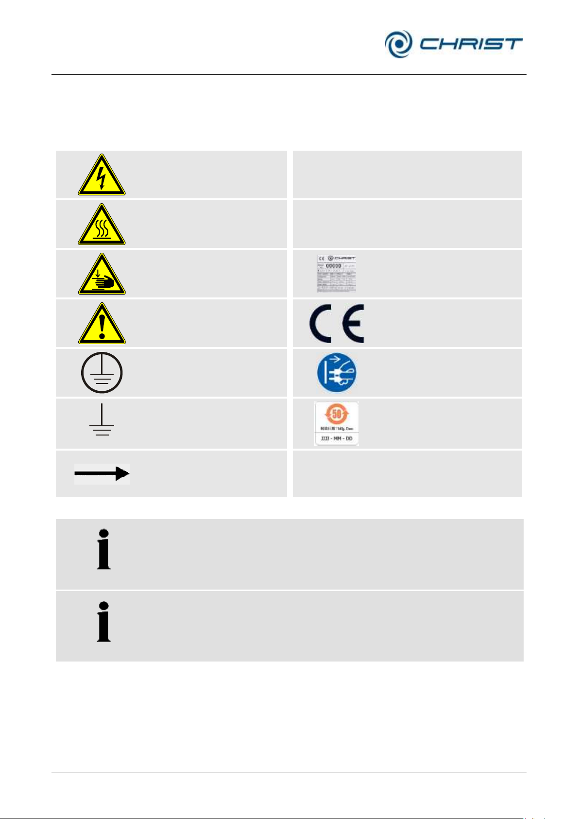
NOTE
Safety indications on the rotational vacuum concentrator must be kept
readable at all times. If necessary, they must be replaced.
NOTE
Not all of the symbols/labels are used for this RVC type.
3 Safety
3.1 Marking of the unit
The following symbols are used for CHRIST RVC:
Page 17
Rotational Vacuum Concentrator RVC 2-33 CDplus
with infrared heating
3 Safety
Version 08/2009, Rev. 3.3 of 03/07/2016 • sb
17 / 88
Translation of the original operating manual
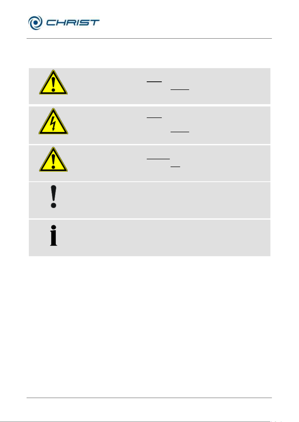
DANGER
This symbol stands for a direct hazard to the life and health of persons.
Non-observance of these symbols causes serious health problems up to
life-endangering injuries.
DANGER
This symbol stands for a direct hazard to the life and health of persons
due to electrical voltage.
Non-observance of these symbols causes serious health problems up to
life-endangering injuries.
WARNING
This symbol stands for a potential hazard to the life and health of persons.
Non-observance of these symbols can cause serious health problems up
to life-endangering injuries.
CAUTION
This symbol indicates a potentially hazardous situation
Non-observance of these notes can cause minor injuries or damage to
property.
NOTE
This symbol indicates important information.
3.2 Explanation of the symbols and notes
This operating manual uses the following names and symbols to indicate
hazards:
Page 18

Rotational Vacuum Concentrator RVC 2-33 CDplus
with infrared heating
3 Safety
18 / 88
Version 08/2009, Rev. 3.3 of 03/07/2016 • sb
Translation of the original operating manual
3.3 Responsibility of the operator
The operator is responsible for authorising only qualified personnel to work
on the RVC (see chapter 3.4 - "Operating personnel").
The areas of responsibility of the personnel concerning the operation,
maintenance, and care of the unit must be clearly defined.
The safety-conscious work of the personnel in compliance with the
operating manual and the relevant EC and national health and safety
regulations as well as with the accident prevention regulations must be
checked at regular intervals (e.g. every month).
The RVC must be maintained regularly (see chapter 8 - "Maintenance and
service").
3.4 Operating personnel
Persons operating the unit must
• be familiar with the fundamental regulations concerning workplace
safety and accident prevention
• have read and understood this operating manual (and in particular the
safety sections and warning notes) and confirmed this with their
signature.
3.5 Informal safety instructions
This operating manual is part of the product.
• The operating manual must be kept at the location of use of the RVC.
Ensure that it is accessible at all times.
• The operating manual must be handed over to any subsequent owner
or operator of the RVC.
• Any changes made must be added to the operating manual.
• In addition to the operating manual, the general and local rules and
regulations concerning the prevention of accidents and the protection of
the environment must also be supplied.
• Safety and danger indications on the RVC must be kept readable at all
times. If necessary, they must be replaced.
Page 19

Rotational Vacuum Concentrator RVC 2-33 CDplus
with infrared heating
3 Safety
Version 08/2009, Rev. 3.3 of 03/07/2016 • sb
19 / 88
Translation of the original operating manual
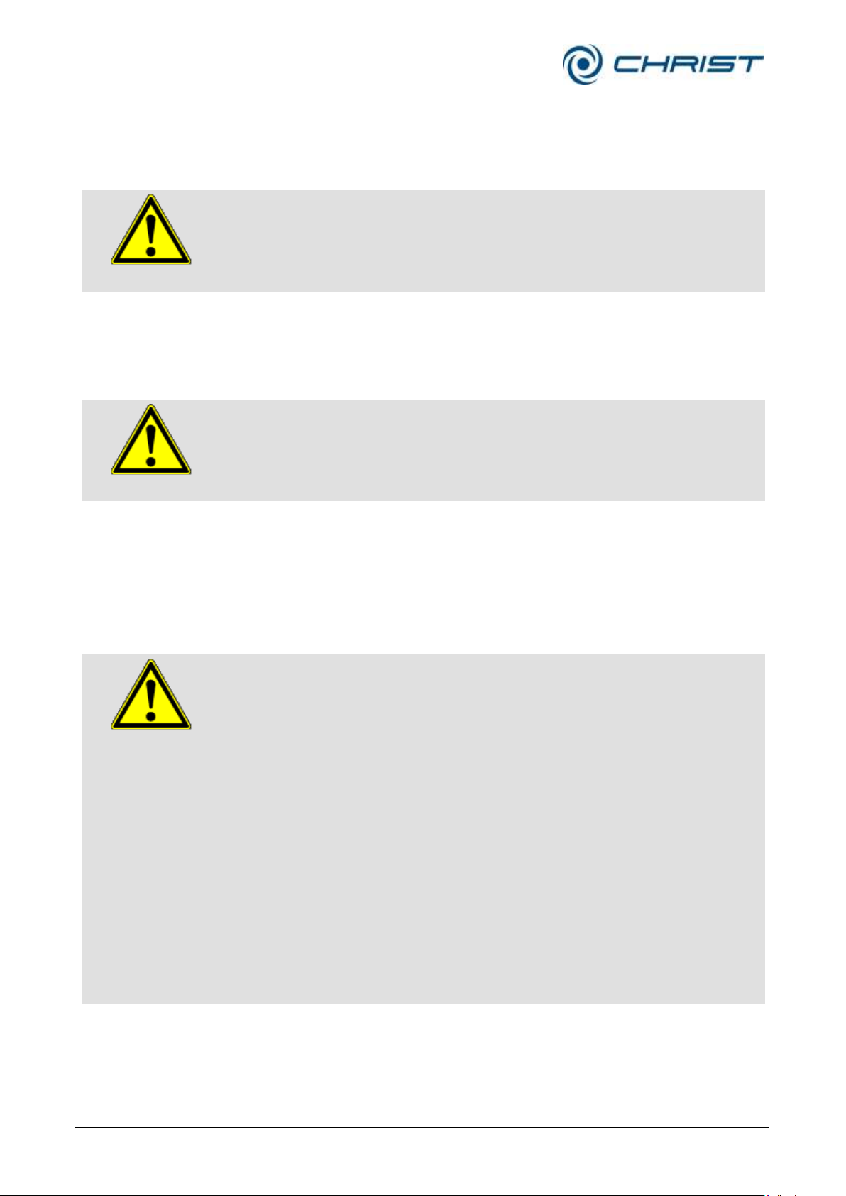
DANGER
• Ensure that the local mains voltage matches the nominal voltage that is
stated on the name plate.
• Do not place any dangerous material, e.g. glass vessels containing
liquid substances, within the safety area of 30 cm around the RVC.
Spilled liquids may get into the RVC and damage the electrical or
mechanical components.
• Work on the power supply system must only be performed by certified
electricians.
• Inspect the electrical equipment of the unit regularly. Defects such as
loose or burnt cables must be eliminated immediately.
WARNING
• Do not use the RVC if it was installed incorrectly.
• Do not use the RVC without panels.
• Do not use the RVC with accessories that show signs of damage.
• Only use the RVC with accessories that have been approved by the
manufacturer. In case of doubt, contact the manufacturer (see chapter
7.2 - "Service contact").
• Do not hold your fingers between the lid and the housing when closing
the lid. Risk of crushing!
• Do not hit or move the RVC during its operation.
• Do not lean against or rest on the RVC during its operation.
• Check the RVC and accessories before every start-up for any visible
signs of damage.
• Do not evaporate any substances that could damage the material of
the rotors, rotor chamber or lid of the RVC in any way. Highly corrosive
substances (e.g. hydrogen chloride HCl) damage the material and
affect the mechanical strength of the rotors and accessories.
• Stop the RVC immediately in the event of a malfunction. Eliminate the
malfunction or contact the after-sales service of Martin Christ
Gefriertrocknungsanlagen GmbH (see chapter 7 - "Malfunctions and
error correction").
• Ensure that all repairs are performed only by authorised and
specialised personnel (see chapter 7.2 - "Service contact").
3.6 Safety instructions
3.6.1 Electrical safety
CHRIST rotational vacuum concentrators are units of safety class I. The
RVCs are equipped with a three-wire power cord and a 230 VAC safety
plug with earthing contact. Please comply with the following points in order
to preserve this safety feature:
3.6.2 Mechanical safety
In order to ensure the safe operation of the RVC, please comply with the
following points:
Page 20
Rotational Vacuum Concentrator RVC 2-33 CDplus
with infrared heating
3 Safety
20 / 88
Version 08/2009, Rev. 3.3 of 03/07/2016 • sb
Translation of the original operating manual
GEFAHR
• Always use fuses of the same type and rating.
• Do not evaporate explosive or inflammable substances.
• Do not use the RVC within hazardous locations where there is a risk of
explosion.
DANGER
• Open and close the lid at the heat-insulated handle!
• Ensure that no limbs come into contact with hot unit parts or
accessories. Danger of burns!
• Wear heat-resistant gloves when inserting or removing the rotors.
DANGER
• Infectious, toxic, pathogenic, and radioactive substances must be
evaporated in suitable accessories. Take suitable precautions for your
own safety!
• Do not evaporate corrosive products (especially substances containing
acids) without special protective measures and devices such as, for
example, a cooling trap for the protection of the vacuum pump. Contact
the manufacturer (see chapter 7.2 - "Service contact").
• Special caution is necessary when handling azides, as a dangerous
explosive develops in combination with copper or nonferrous metals! It
is absolutely necessary to contact the manufacturer (see chapter 7.2 "Service contact").
• Keep informed about local measures to avoid harmful emissions
(depending on the substances to be evaporated).
• As personal protective equipment, safety gloves are required for the
use of the RVC.
The materials to be evaporated may, however, require additional
special safety measures (e.g. drying of infectious, toxic, radioactive, or
pathogenic substances)
3.6.3 Fire prevention
Fuses protect certain electrical circuits within the RVC against over-current
conditions.
3.6.4 Thermal safety
During the evaporation process, the housing, lid and interior of the RVC
can reach surface temperatures of more than +50°C.
3.6.5 Chemical and biological safety
If pathogenic, toxic, or radioactive samples are intended to be evaporated,
it is in the responsibility of the user to ensure that all necessary safety
regulations, guidelines, precautions, and practices are adhered to
accordingly.
Page 21

Rotational Vacuum Concentrator RVC 2-33 CDplus
with infrared heating
3 Safety
Version 08/2009, Rev. 3.3 of 03/07/2016 • sb
21 / 88
Translation of the original operating manual
WARNING
• Ensure that the RVC was set up and connected properly (see chapter
5 - "Set-up and connection").
• Maintain a safety distance of at least 30 cm (12 inches) around the
RVC.
• Do not store any dangerous goods in the safety area of the RVC.
• Do not stay in the safety area longer than what is absolutely necessary
for the operation of the RVC.
• Only use accessories that have been approved by the manufacturer
(except for commercial vessels made of glass or synthetic materials).
We explicitly warn against the use of equipment of poor quality.
Breaking glass or bursting vessels can cause dangerous imbalances.
• Observe the instructions on the installation of accessories (see chapter
6.4.3 - "Installation of accessories").
3.6.6 Safety instructions for evaporation
The following instructions must be observed prior to every evaporation
process:
3.7 Safety devices
3.7.1 Lid lock device
3.7.2 System check
3.7.3 Power failure safety
3.7.4 Earth conductor check
The RVC can only be started when the lid is properly closed. The lid can
only be opened when the rotor has stopped. If the lid is open, the RVC
cannot be started.
An internal system check monitors the data transfer and sensor signals with
regard to plausibility. Errors are detected by continuous self-monitoring of
the system. Error messages are displayed in the process & equipment info
menu (see chapter 6.5.3.4 - "Process and equipment information" or
chapter 7.1.1 - "Error messages").
The unit stores the current process parameters cyclically. In the event of a
power failure, the electromagnetic stop valve will close automatically, the
rotor chamber will be aerated by the aeration valve and the rotor
decelerates brakeless. After the restart of the power supply, the
evaporation process continues with the last stored parameters.
For the earth conductor check, there is an equipotential bonding screw on
the rear panel of the RVC. An earth conductor check can be carried out
with the aid of a suitable measuring instrument.
Page 22

Rotational Vacuum Concentrator RVC 2-33 CDplus
with infrared heating
3 Safety
22 / 88
Version 08/2009, Rev. 3.3 of 03/07/2016 • sb
Translation of the original operating manual
DANGER
Fire:
• A fire in the electrical control system must be extinguished with a CO2
fire extinguisher!
• Burning oil must be extinguished with a CO2 fire extinguisher or powder
fire extinguisher!
Hazardous electrical incident:
• Set the mains power switch of the control system to the "0" position in
order to interrupt the power supply completely.
Burns:
• Small-area burns (e.g. finger) should be cooled immediately with
lukewarm water for approximately 2 minutes.
• Large-area burns should not be cooled because of the resulting risk of
hypothermia.
• Cover the burns loosely and in a sterile manner (e.g. with a sterile
dressing).
• Cover the injured person with a blanket.
IF IN DOUBT, CALL THE EMERGENCY PHYSICIAN (AMBULANCE)!
3.8 Procedures in the event of hazards and accidents
3.9 Remaining hazards
All CHRIST rotational vacuum concentrators were built state- of- the- art
and according to the accepted safety rules. However, danger to life and
limb of the operator, or of third parties, or impairments of the units or other
material assets cannot be completely excluded when the units are being
used.
• Use the RVC only for the purpose that it was originally intended for (see
chapter 1.2 - "Intended use").
• Use the RVC only if it is in a perfect running state.
• Immediately eliminate any problems that can affect safety.
Page 23

Rotational Vacuum Concentrator RVC 2-33 CDplus
with infrared heating
4 Storage and transport
Version 08/2009, Rev. 3.3 of 03/07/2016 • sb
23 / 88
Translation of the original operating manual
RVC 2-33 IR
Height:
325 mm
Height with open lid:
715 mm
Width:
550 mm
Depth):
520 mm + 20 mm vacuum connection
Weight:
approx. 49 kg
CAUTION
The RVC 2-33 IR weighs approx. 49 kg!
4 Storage and transport
4.1 Storage conditions
4.2 Dimensions and weight
In order to ensure the protection against mechanical and climatic
influences, the guidelines of the German Federal Association for Wooden
Packages, Pallets, and Export Packaging (Bundesverband Holzpackmittel,
Paletten, Exportverpackung e.V.), the so-called HPE packaging guidelines,
must be applied when packing and storing the RVC.
The storage must be:
• dust-free
• dry
• free from excessive temperature fluctuations
• free from mechanical load.
Values for the RVC without a vacuum pump:
4.3 Packaging
The RVC is packaged in a cardboard box or in a wooden crate, depending
on the scope of supply.
• After opening the packaging, take out the box containing the
accessories.
• Remove the packaging material.
• Lift the RVC upwards and out of the crate/cardboard box. When lifting
the unit, always reach under it from the side.
Page 24
Rotational Vacuum Concentrator RVC 2-33 CDplus
with infrared heating
4 Storage and transport
24 / 88
Version 08/2009, Rev. 3.3 of 03/07/2016 • sb
Translation of the original operating manual
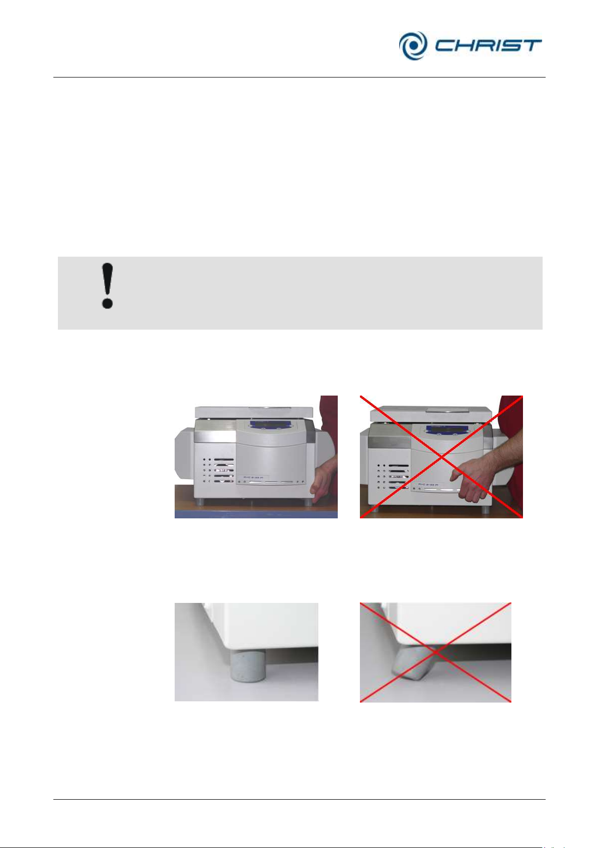
CAUTION
The RVC 2-33 IR weighs approx. 49 kg!
correct
incorrect
Fig. 5: Lifting the RVC
correct
incorrect
Fig. 6: Unit feet
4.4 Transport safety device
The following transport safety devices must be removed prior to start-up:
• The polystyrene element that covers the valve block at the back of the
RVC must be removed.
• Remove the layers of paper between the lid and rotor chamber; they
prevent the lid from getting stuck during the transport.
4.5 On-site transport
• The RVC can be transported by a suitable number of persons who
reach under it from the sides.
• When lifting the RVC, always reach under it from the side. Do not grab
the unit at the plastic control panel (see the illustrations below).
• When setting the unit down, ensure that the feet are upright (see the
illustrations below).
• Use suitable packaging for the transport, and if at all possible, the
original packaging.
Page 25

Rotational Vacuum Concentrator RVC 2-33 CDplus
with infrared heating
5 Set-up and connection
Version 08/2009, Rev. 3.3 of 03/07/2016 • sb
25 / 88
Translation of the original operating manual
DANGER
The operating voltage on the name plate must correspond to the local
supply voltage!
5 Set-up and connection
5.1 Installation site
5.2 Power supply
Operate the RVC only in closed and dry rooms.
• The table must be stable and have a solid, even tabletop.
• Ensure sufficient ventilation. Do not place any paper, cloth, or similar
material behind or under the unit, since otherwise the air circulation will
be impaired.
• Keep a safety distance of at least 30 cm from the wall so that the vents
in the unit remain fully effective.
• The ambient temperature must be in the range of +10°C to +25°C.
• Do not subject the RVC to thermal stress, e.g. by positioning it near
heat generators.
• Avoid direct sunlight (UV radiation).
5.2.1 Connection
CHRIST rotational vacuum concentrators are units of safety class I.Units of
the type RVC 2-33 IR have a three-wire power cord with an IEC C13
connector (see chapter 10 - "Technical data").
An equipotential bonding screw is located on the back (see chapter 2.1.1 "Functional and operating elements"). This equipotential bonding screw can
be used to perform an earth conductor check.
5.2.2 Customer-provided fuses
Typically, the RVC must be protected with 16 Amp G fuses that are to be
provided by the customer.
Page 26
Rotational Vacuum Concentrator RVC 2-33 CDplus
with infrared heating
5 Set-up and connection
26 / 88
Version 08/2009, Rev. 3.3 of 03/07/2016 • sb
Translation of the original operating manual
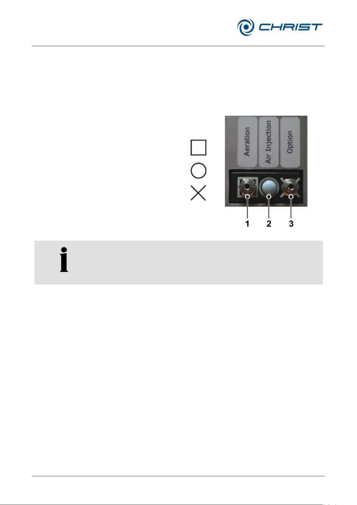
1 Aeration
2 Air injection
3 Fastener for non-required
connection element
NOTE
Unpressurised inert gas can also be used for aerating the rotor chamber.
5.3 Aeration and micro injection valve (Valve block)
The rotational vacuum concentrator is equipped with an electromagnetic
aeration and injection valve. The rotor chamber is aerated through this
valve after the end of the evaporation process (manual and program
mode).
In addition, this valve can also inject air. If the vacuum value falls below the
preset value, this valve opens briefly to ensure a constant vacuum.
Fig. 7: Valve block
Connecting combinations:
1. Connection for aeration and air injection with ambient air (state of
delivery)
1 Aeration hose connection
2 Air filter
3 Fastener for non-required connection element; here: hose nozzle
2. Connection for aeration with ambient air and air injectio" with inert gas
1 Aeration hose connection
2 Air injection hose nozzle
3 Fastener for non-required connection element; here: air filter
Page 27
Rotational Vacuum Concentrator RVC 2-33 CDplus
with infrared heating
5 Set-up and connection
Version 08/2009, Rev. 3.3 of 03/07/2016 • sb
27 / 88
Translation of the original operating manual
CAUTION
If gas (e.g. inert gas) is supplied through the hose nozzle for aeration or for
“air injection”, the threads of the hose nozzles must be sealed with thread
sealant, e.g. Loctite® 542 (Loctite® part number: 54223, bottle with 10ml).
NOTE
The small flange connections must be installed correctly in order to
prevent leaks (see chapter 7.1.5 - "Small flange connections ").
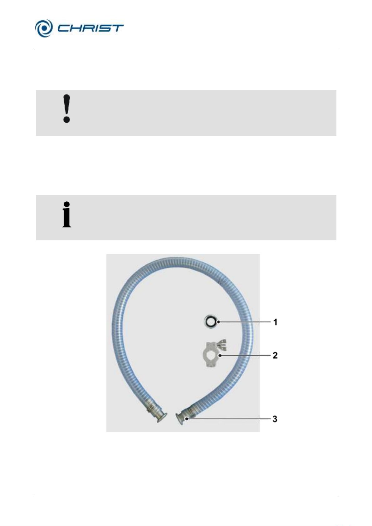
1 Centring ring
2 Clamping ring
3 Flange connection
3. Connection for aeration and air injection with inert gas
1 Aeration hose connection
2 Air injection hose nozzle
3 Fastener for non-required connection element; here: air filter
5.4 Vacuum connections
The vacuum connection is realised by way of a vacuum hose with standard
flange connections, clamping rings, or chains, and centring rings.
Fig. 1: Connecting pieces for vacuum connection
Page 28
Rotational Vacuum Concentrator RVC 2-33 CDplus
with infrared heating
5 Set-up and connection
28 / 88
Version 08/2009, Rev. 3.3 of 03/07/2016 • sb
Translation of the original operating manual
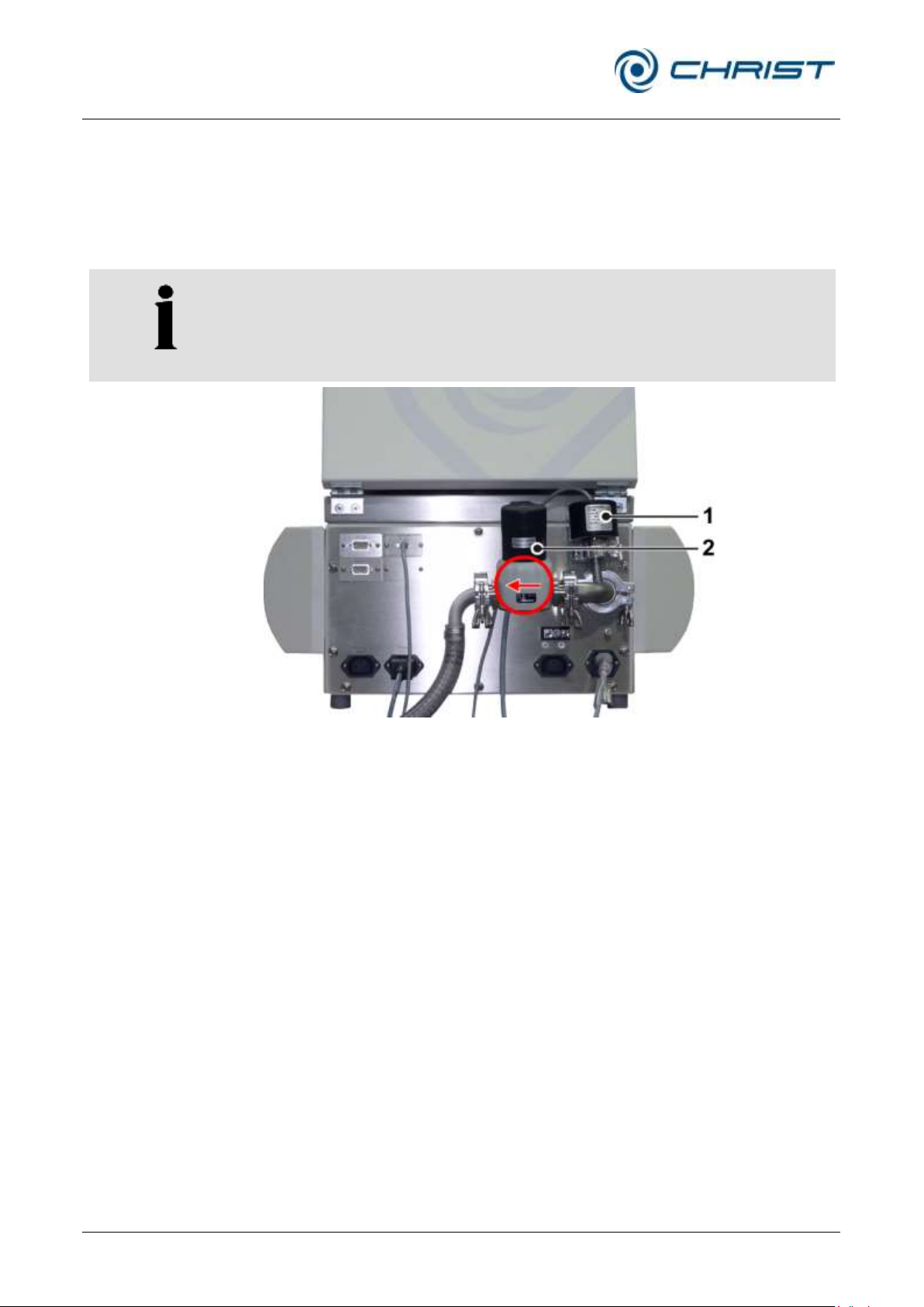
NOTE
Observe the installation direction of the pressure control valve!
1 Vacuum sensor
2 Pressure control valve
5.5 Option: Pressure control valve and vacuum sensor
If a pressure control valve and a vacuum sensor are used, they must be
installed between the rotational vacuum concentrator and the vacuum
pump, and they must be connected to the marked IEC C14 connector at
the back of the unit (see chapter 2.1.1 - "Functional and operating
elements").
Fig. 8: Installation of the pressure control valve and the vacuum sensor
Page 29
Rotational Vacuum Concentrator RVC 2-33 CDplus
with infrared heating
5 Set-up and connection
Version 08/2009, Rev. 3.3 of 03/07/2016 • sb
29 / 88
Translation of the original operating manual
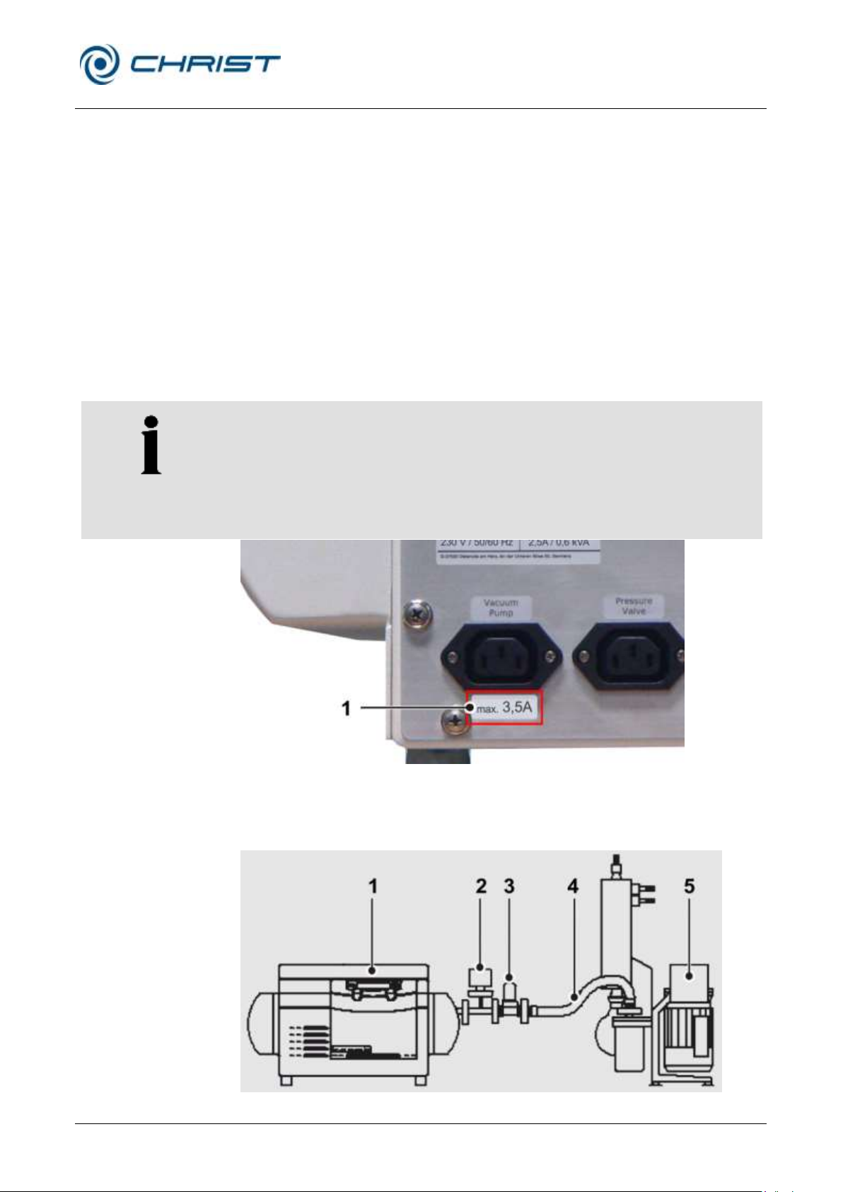
NOTE
The vacuum pump is supplied with power by the unit, but the maximum
current for the vacuum pump is limited. It is absolutely essential to refer to
the label of the electrical outlet for the vacuum pump (see the following
picture)!
If the current requirement of the vacuum pump is higher than the value that
is stated on the label, the pump must be supplied separately via an on-site
power socket.
1 Label indicating the
maximum current
1 RVC
2 Vacuum sensor
3 Stop valve
4 Vacuum hose
5 Vacuum pump
5.6 Connection of a vacuum pump and/or a cooling trap
In order to withdraw and condense the vapours that are formed, the RVC
5.6.1 Withdrawal of the vapours by a vacuum pump
can be connected with further components.
The vapours are withdrawn by a vacuum pump, e.g. the vacuum diaphragm
pump for chemical applications”MZ 2C” or “MD 4C”, followed by
condensation in a liquid-cooled emission condenser. This application is
suitable for low-boiling samples containing solvents.
The vacuum pump must be connected to the RVC. The connector of the
stop valve must be plugged into the socket on the back of the unit (see
chapter 2.1.1 - "Functional and operating elements").
Fig. 9: Indication of the maximum current for the vacuum pump (example)
The connector of the stop valve must be plugged into the socket "Stop
valve" on the back of the unit.
Fig. 10: Combination of the RVC with a vacuum pump and a stop valve
Page 30
Rotational Vacuum Concentrator RVC 2-33 CDplus
with infrared heating
5 Set-up and connection
30 / 88
Version 08/2009, Rev. 3.3 of 03/07/2016 • sb
Translation of the original operating manual
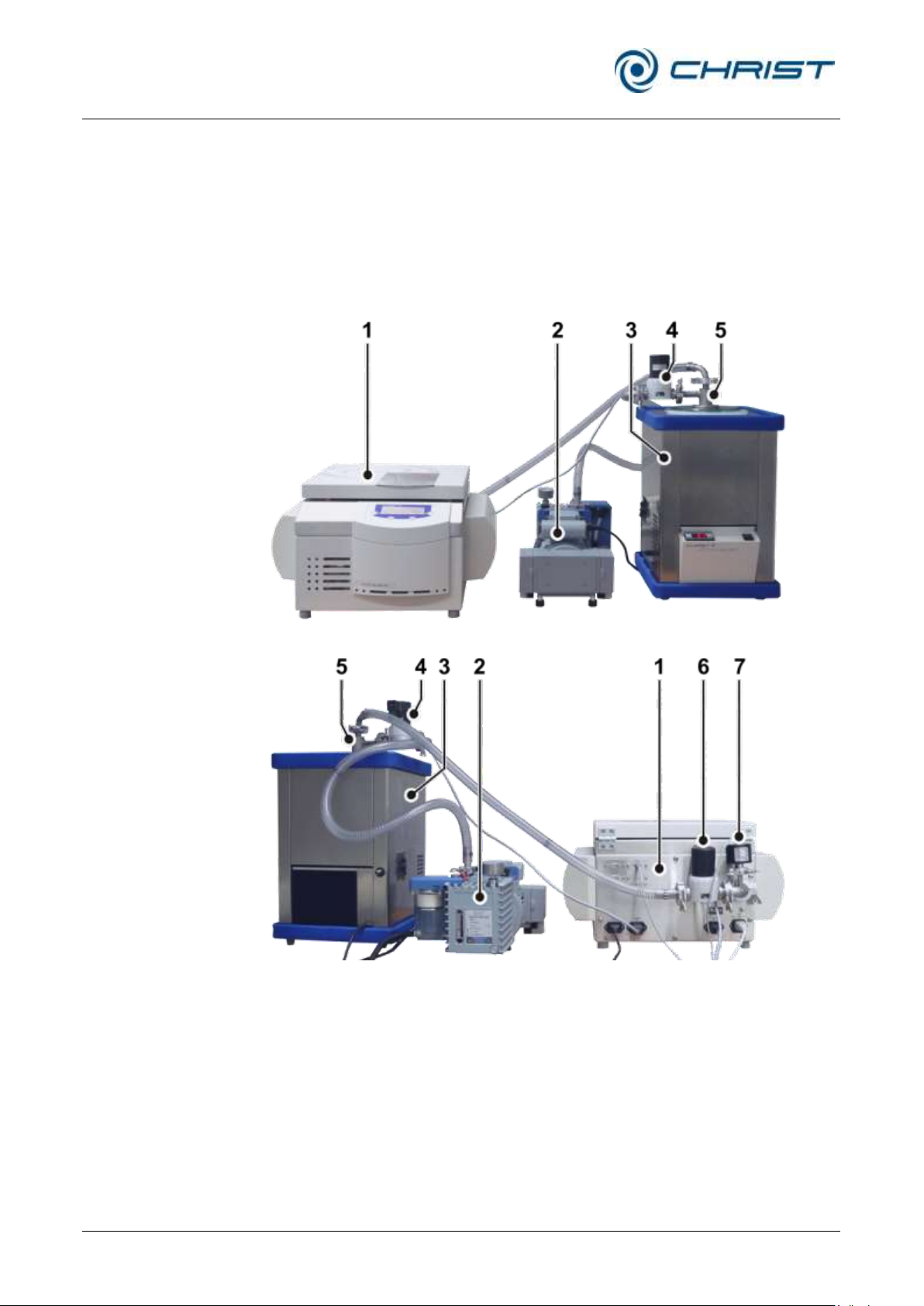
1 RVC
2 Vacuum pump
3 Cooling trap
4 Pressure control valve
5 Cover with connecting
hoses
6 Stop valve
7 Vacuum sensor
5.6.2 Condensation of the vapours upstream of the vacuum pump in a cooling
trap
The vapours are condensed upstream of the vacuum pump in a cooling
trap, e.g.”CT 02-50” or “CT 04-50”.
The application is suitable for water-base, low-boiling samples containing
solvents. The RVC, the cooling trap and the vacuum pump must be
connected. The connector of the stop valve must be plugged into the
socket on the back of the unit.
Fig. 11: Combination of the RVC with vacuum pump and cooling trap (front view)
Page 31
Rotational Vacuum Concentrator RVC 2-33 CDplus
with infrared heating
5 Set-up and connection
Version 08/2009, Rev. 3.3 of 03/07/2016 • sb
31 / 88
Translation of the original operating manual
CHRIST
RVC
REMOTE
RS 232
CHRIST
FD cooling trap
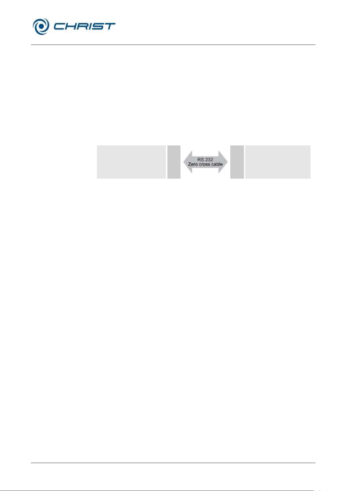
5.6.2.1 Option: Remote control of the cooling trap via RVC
If CHRIST freeze dryers are used as a cooling trap, they can be remotecontrolled by the rotational vacuum concentrator. In this case, the cooling
trap will be automatically activated by the rotational vacuum concentrator
during the warm-up and evaporation phase. In the standby mode, the
cooling trap will be either switched off or continue operation, depending on
the choosen option (chapter 6.5.3.5 - "Options" Settings / Continuous
operation coldtrap"). The ice condenser temperature is indicated in the
values window of the rotational vacuum concentrator.
The cooling trap must be connected to the rotational vacuum concentrator
with the aid of a zero cross cable (part no. 222 000). In addition, the option
"Cooling trap control" must be activated (see chapter 6.5.3.5 - "Options").
Page 32

Rotational Vacuum Concentrator RVC 2-33 CDplus
with infrared heating
6 Operation
32 / 88
Version 08/2009, Rev. 3.3 of 03/07/2016 • sb
Translation of the original operating manual
WARNING
Before the initial start-up, please ensure that your RVC is properly set up
and installed (see chapter 5 - "Set-up and connection")
DANGER
Do not place your fingers between the lid and the housing when closing
the lid. Risk of crushing!
6 Operation
6.1 Initial start-up
6.2 Switching the RVC on
• Press the mains power switch on the right-hand side of the unit.
The CDplus control unit performs a self-test and an initialisation. This may
take several seconds.
• Follow the safety instructions and hazard warnings !
6.3 Opening and closing the lid
The lid can be opened if the rotor chamber is aerated and if the rotor is at a
standstill. The rotational vacuum concentrator cannot be started if the lid is
open.
• Select "mode" with the left-hand function key.
• Select "Open lid" with the up and down keys.
• To close, press slightly on the lid until both locks are locked.
Page 33
Rotational Vacuum Concentrator RVC 2-33 CDplus
with infrared heating
6 Operation
Version 08/2009, Rev. 3.3 of 03/07/2016 • sb
33 / 88
Translation of the original operating manual
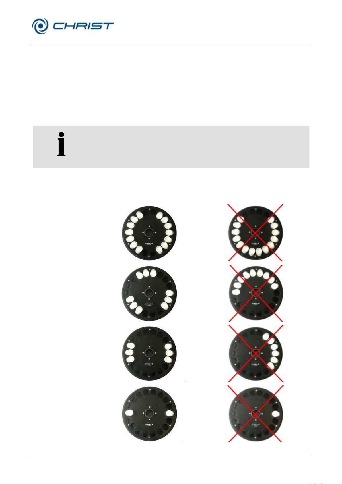
NOTE
Depending on the version, up to three rotors can be pushed onto the rotor
shaft at the same time.
correct
incorrect
6.4 Installation of rotors and accessories
6.4.1 Installation of angle rotors
• Only use inserts that are suitable for the rotor (see chapter 11.2 - "Rotor
program").
• Always load the opposite inserts of the rotors with the same accessories
and fill to avoid imbalance.
• Push the loaded rotor onto the rotor shaft until it reaches the stop.
• Follow the safety instructions and hazard warnings (see chapter 3 -
"Safety")!
Fig. 12: Symmetrical loading of angle rotors
Page 34

Rotational Vacuum Concentrator RVC 2-33 CDplus
with infrared heating
6 Operation
34 / 88
Version 08/2009, Rev. 3.3 of 03/07/2016 • sb
Translation of the original operating manual
6.4.2 Installation of swing-out rotors
• Push the loaded rotor onto the rotor shaft until it reaches the stop.
• Follow the safety instructions and hazard warnings (see chapter 3 -
"Safety")!
6.4.3 Installation of accessories
• Only use inserts that are suitable for the rotor (see chapter 11.2 - "Rotor
program").
• In swing-out rotors, all places of a rotor must be loaded with buckets..
• Always load the opposite inserts of the rotors with the same accessories
and fill to avoid imbalance.
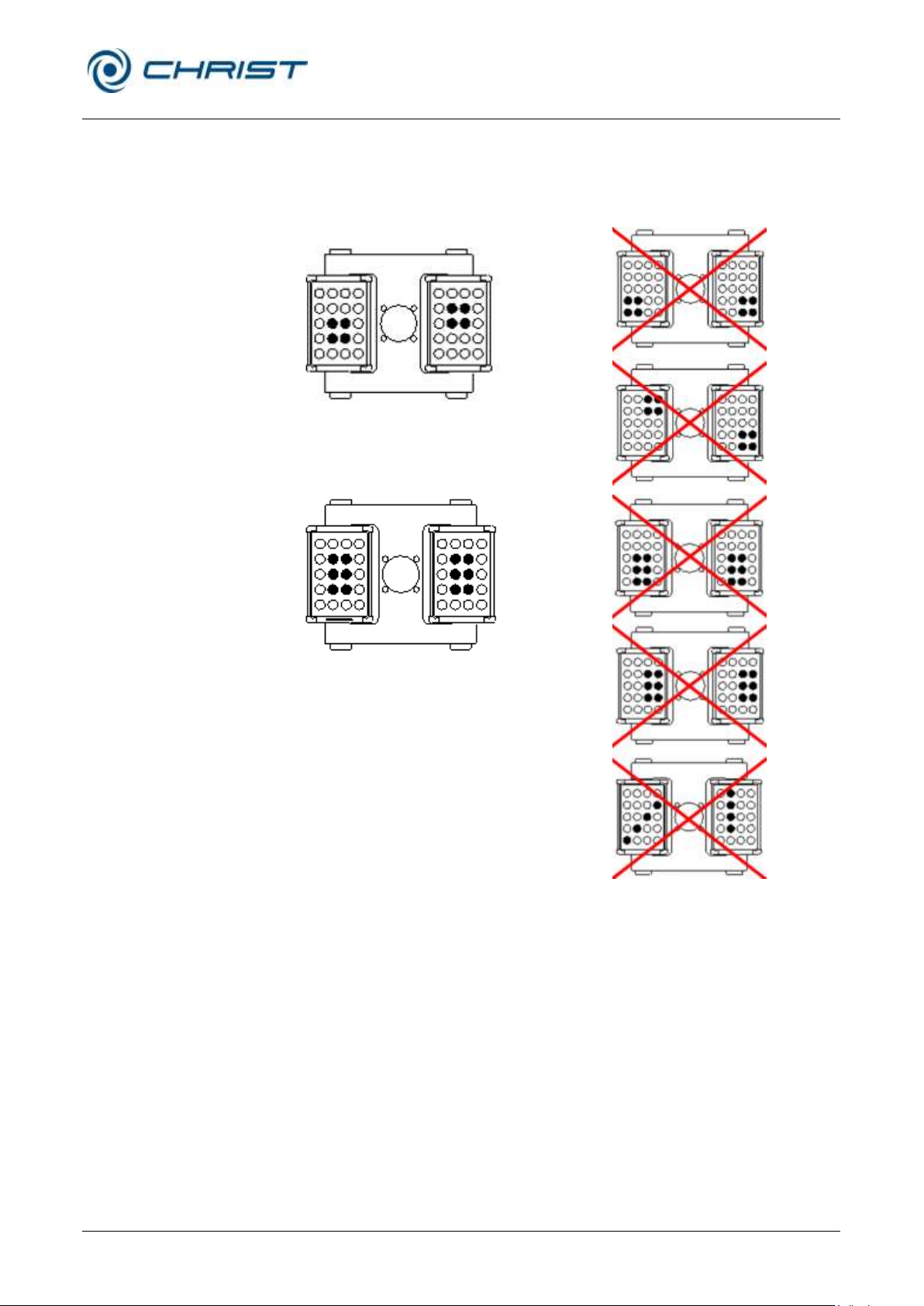
Evaporation with different tube sizes
Working with different tube sizes is possible. In this case, however, it is
very important that the inserts are installed symmetrically (see figure).
Fig. 13: Permissible loading of the swing-out rotor with different tube sizes
Page 35
Rotational Vacuum Concentrator RVC 2-33 CDplus
with infrared heating
6 Operation
Version 08/2009, Rev. 3.3 of 03/07/2016 • sb
35 / 88
Translation of the original operating manual
correct
incorrect
Evaporation with low capacity
The tubes must be installed symmetrically so that the buckets and their
inserts are loaded evenly to avoid imbalance.
Fig. 14: Permissible loading of swing-out rotors with low capacity
6.4.3.1 Tubes
• Load the tubes outside of the rotational vacuum concentrator. Solvents
• Fill the tubes carefully and arrange them according to their weight.
• Follow the safety instructions and hazard warnings (see chapter 3 -
in the buckets or rotor blocks cause corrosion.
"Safety")!
Page 36
Rotational Vacuum Concentrator RVC 2-33 CDplus
with infrared heating
6 Operation
36 / 88
Version 08/2009, Rev. 3.3 of 03/07/2016 • sb
Translation of the original operating manual
correct
incorrect
correct
incorrect
at a standstill
under rotation
6.4.3.2 Rotor blocks
6.4.3.3 Buckets
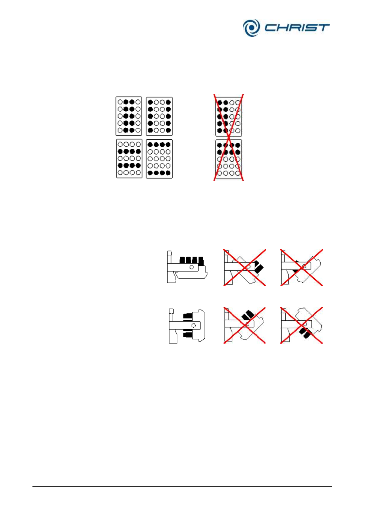
• Always load the rotor blocks symmetrically with the same accessories
and fill to avoid imbalance.
Fig. 15: Symmetrical loading of the rotor blocks
• Load each bucket symmetrically to its pivotal point to ensure swinging
to 90° under rotation.
Fig. 16: Symmetrical loading of the buckets
Page 37
Rotational Vacuum Concentrator RVC 2-33 CDplus
with infrared heating
6 Operation
Version 08/2009, Rev. 3.3 of 03/07/2016 • sb
37 / 88
Translation of the original operating manual
correct
incorrect
at a standstill
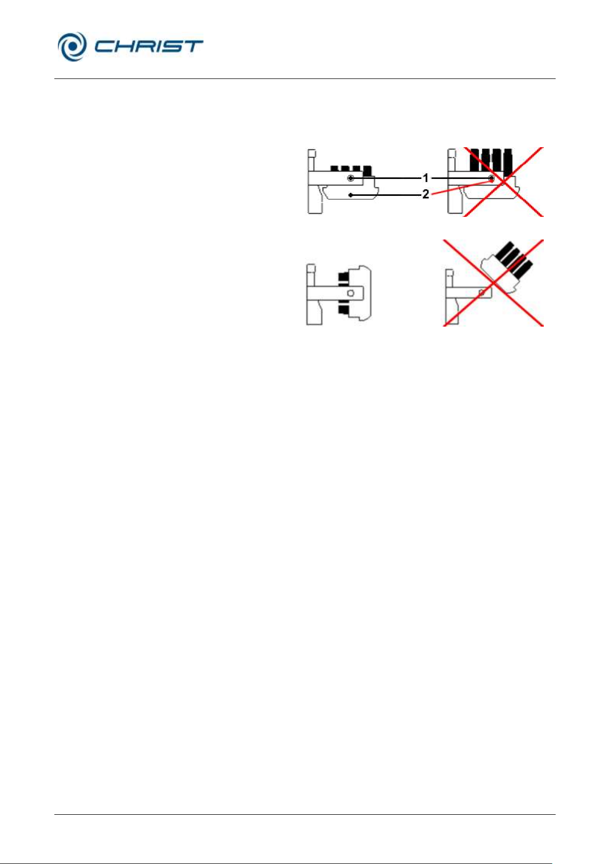
1 Pivotal point
2 Balance point
under rotation
• The balance point of the loaded bucket must be located considerably
below the pivotal point. If the balance point is too near the pivotal point,
the loaded bucket can be levered out of the bearings.
Fig. 17: Loading of buckets considering the balance point
Page 38
Rotational Vacuum Concentrator RVC 2-33 CDplus
with infrared heating
6 Operation
38 / 88
Version 08/2009, Rev. 3.3 of 03/07/2016 • sb
Translation of the original operating manual
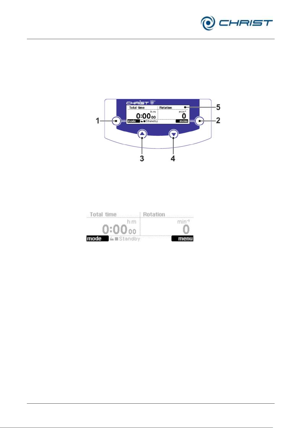
1 Left function key
2 Right function key
3 "Up" key
4 "Down" key
5 Display
6.5 CDplus control system
The control system CDplus (“Concentrator Display plus”) stands for a
convenient user interface for the intuitive control of evaporation processes
6.5.1 User interface
under rotation.
Fig. 18: User interface of the CDplus control system
Function keys (1+2)
The function of these keys depends on the menus and operating states of
the installation. The current key function is displayed in the black field next
to the key.
Fig. 19: Display of the assignment of the function keys; here: left key "mode",
right key "menu"
Up and down keys (3+4)
These keys are used to select the available functions and values or to
change the selected parameter values.
In addition, these keys also control the indication of the measurement value
channels in the value windows. The "up" key is assigned to the left value
window, whereas the "down" key controls the right value window.
• For a selection, press the "up" or "down" key repeatedly until the
desired measurement value channel is indicated in the respective value
window.
Page 39
Rotational Vacuum Concentrator RVC 2-33 CDplus
with infrared heating
6 Operation
Version 08/2009, Rev. 3.3 of 03/07/2016 • sb
39 / 88
Translation of the original operating manual
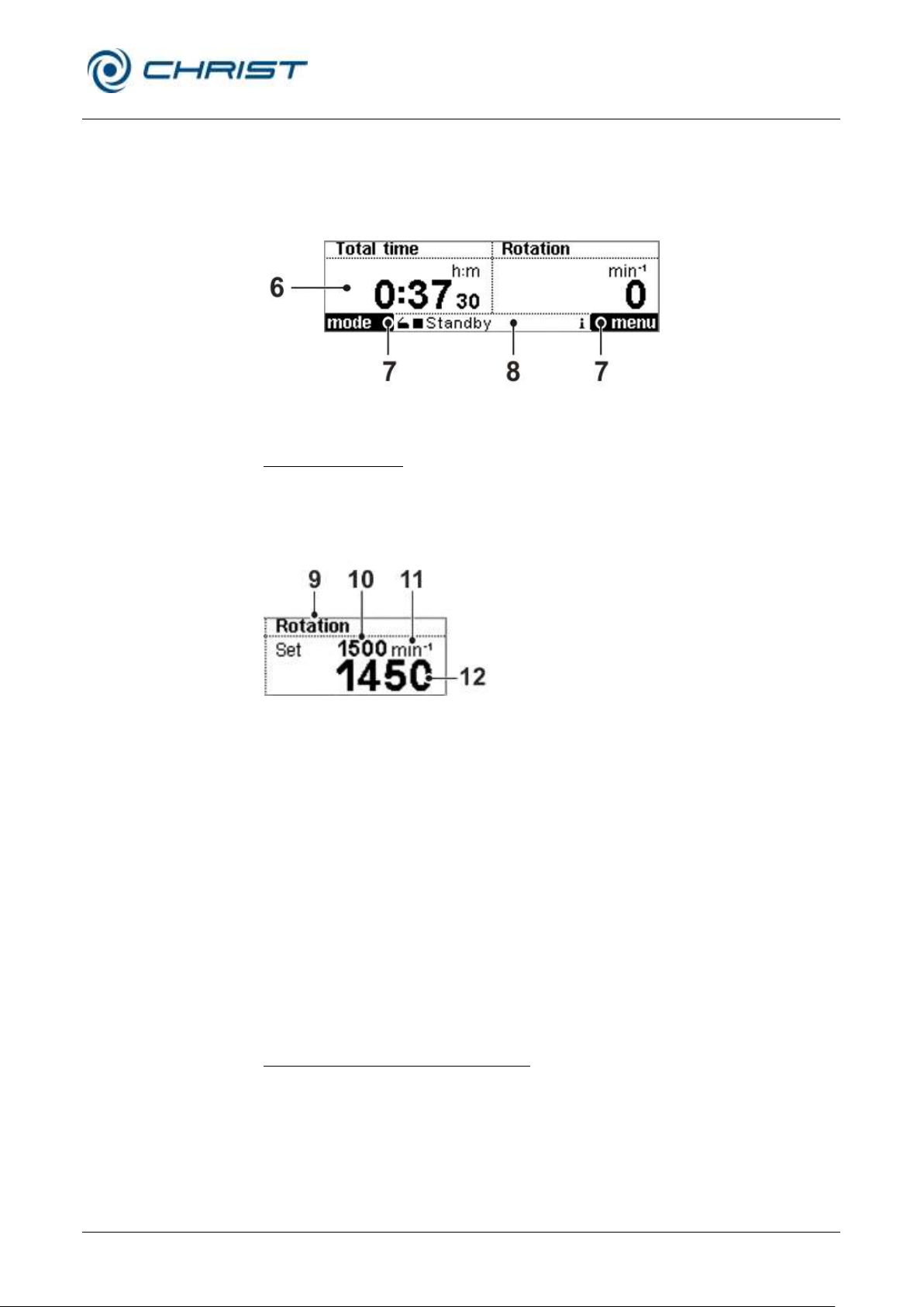
6 Values window
7 Assignment of the
function keys
8 Status bar
9 Measuring channel
10 Set value (only shown
in the run mode)
11 Unit of the measured
value
12 Actual value
Display (5)
The main window of the display is divided into three areas: the values
windows, the assignment of the function keys and the status bar. The main
window shows the process data, e.g. set values and actual values, menues
and process-relevant information (see figure).
Fig. 20: Structure of the CDplus display
Values window (6)
The value windows are displayed after the initialisation of the control
system. There are two value windows with an identical layout. The
indication of the measurement value channels is controlled by way of the
"up" and "down" keys (see above).
Fig. 21: Values window
The available measurement values can be displayed in the values window
on the left as well as in the values window on the right so that a
combination of the following values can be selected:
• Rotor speed
• Vacuum (only if a vacuum sensor is installed)
• Safety pressure (only if a vacuum sensor is installed)
• Rotor chamber temperature
• Ice condenser temperature (only if the option "Cooling trap control" is
used)
• Total time (counts the time of the entire process run)
• Section time (counts the time of an individual phase, e.g. warm-up,
program sections)
Assignment of the function keys (7)
see "function keys" (1+2)
Page 40
Rotational Vacuum Concentrator RVC 2-33 CDplus
with infrared heating
6 Operation
40 / 88
Version 08/2009, Rev. 3.3 of 03/07/2016 • sb
Translation of the original operating manual
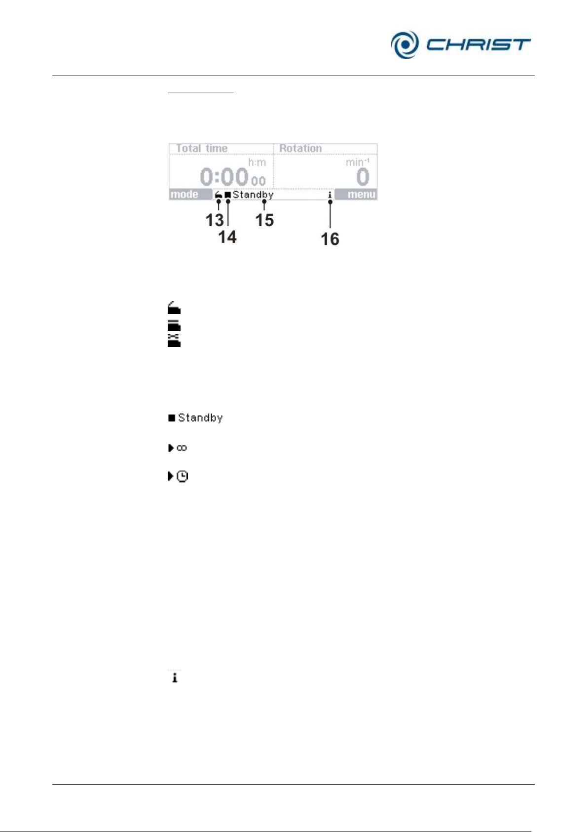
13 Lid status
14 Icon for the operating
mode
15 Active phase
16 Info icon
The lid is open.
The lid is closed.
The lid is not completely closed.
• Press the right or left side of the lid down in order to
close the lid completely.
The rotational vacuum concentrator is in the standby mode.
All aggregates are switched off.
The rotational vacuum concentrator is in the run mode. The
timer is deactivated.
The rotational vacuum concentrator is in the run mode. The
timer is activated.
Open lid
The rotor is at a standstill, the lid can be opened.
Warm-up
The vacuum pump and/or the cooling trap are within the
warm-up phase.
Evaporation
manual
The RVC is within a manual-controlled evaporation run.
Evaporation
program
The RVC is within a program-controlled evaporation run.
If any messages are pending, the info icon flashes every
second to draw the user's attention to error messages,
process messages, or general information concerning the
process or the unit.
The messages can be displayed in the process and
equipment information window (see chapter 6.5.3.4 "Process and equipment information")
Status bar (8)
The status bar shows information regarding the lid status, the operating
mode, the active phase, and pending information. The status bar is visible
at all times.
Fig. 22: Status bar
Lid status (13)
Operating mode (14)
Active phases (15)
Pending information (16)
Page 41
Rotational Vacuum Concentrator RVC 2-33 CDplus
with infrared heating
6 Operation
Version 08/2009, Rev. 3.3 of 03/07/2016 • sb
41 / 88
Translation of the original operating manual
DANGER
During the evaporation process, the housing, the lid and the interior of the
rotational vacuum concentrator can reach surface temperatures of more
than +50°C.
Risk of burns!
6.5.2 Mode
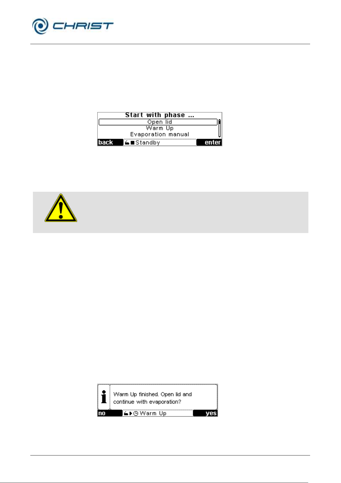
The mode selection can be activated by pressing the left-hand function key
"mode" in the active values window. The following phases are available:
• Press the left-hand function key "mode". The menu "start with phase…"
appears (see figure).
• Select the desired menu item with the up and down keys.
• Press the right-hand function key "enter" to confirm.
Fig. 23: Selecting the mode
Opening the lid
The lid can only be opened if the rotor is at a standstill. It is not possible to
open the lid during an evaporation process.
Warm-up
Before starting an evaporation process, the vacuum pump and the cooling
trap should warm-up until they reach their respective operating
temperatures.
For this purpose, the warm-up phase can be started. The rotor can
optionally be installed. The warm-up time and the set value for heating can
be selected (see chapter 6.5.3.5 - "Options").
During the warm-up:
• The rotor chamber is preheated - with or without rotor - when the lid is
closed.
• The vacuum pump is switched on.
• The cooling trap is switched on if it is connected via the control system
with the rotational vacuum concentrator (see chapter 5.6 - "Connection
of a vacuum pump and/or a cooling trap").If there is no connection, the
cooling trap must be switched on separately.
When the preset warm-up time is over, the control unit displays the
following message:
Fig. 24: Message after the warm-up
• Open the lid and remove the rotor in order to load it with the product or
insert the loaded rotor.
Page 42
Rotational Vacuum Concentrator RVC 2-33 CDplus
with infrared heating
6 Operation
42 / 88
Version 08/2009, Rev. 3.3 of 03/07/2016 • sb
Translation of the original operating manual
NOTE
The function "Evaporation program" can only be selected if a program was
created before (see chapter 6.5.3.2 - "Program administration").
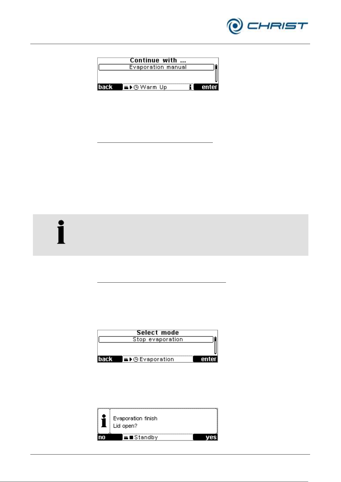
• Close the lid. A menu appears:
Fig. 25: Continuing the evaporation
• Continue the process by selecting "Evaporation manual" or
"Evaporation program".
Stopping the warm-up phase prematurely
During the warm-up phase, the functions "Open lid", "Continue with phase"
or "Stop warm-up" can be selected with the right-hand function key "mode".
The warm-up is stopped by selecting one of the functions.
Manual or program-controlled evaporation
If the unit is in the standby mode, the evaporation phase can be started
directly. For this purpose, select from the menu " Start with phase" the item
"Evaporation manual" or "Evaporation program".
Stopping the evaporation process prematurely
If the timer is active, the evaporation process will be stopped automatically
when the preset time is over. The process can also be aborted manually.
• Open the menu "Select mode" with the left-hand function key.
• Select the function "Stop evaporation“.
• Press the right-hand function key to confirm.
Fig. 26: Stopping an evaporation process
When the evaporation process is stopped, the chamber is completely
aerated and the rotor stops. Then, the system inquires as to whether the lid
should be opened.
Fig. 27: Message after stopping an evaporation process
Page 43
Rotational Vacuum Concentrator RVC 2-33 CDplus
with infrared heating
6 Operation
Version 08/2009, Rev. 3.3 of 03/07/2016 • sb
43 / 88
Translation of the original operating manual
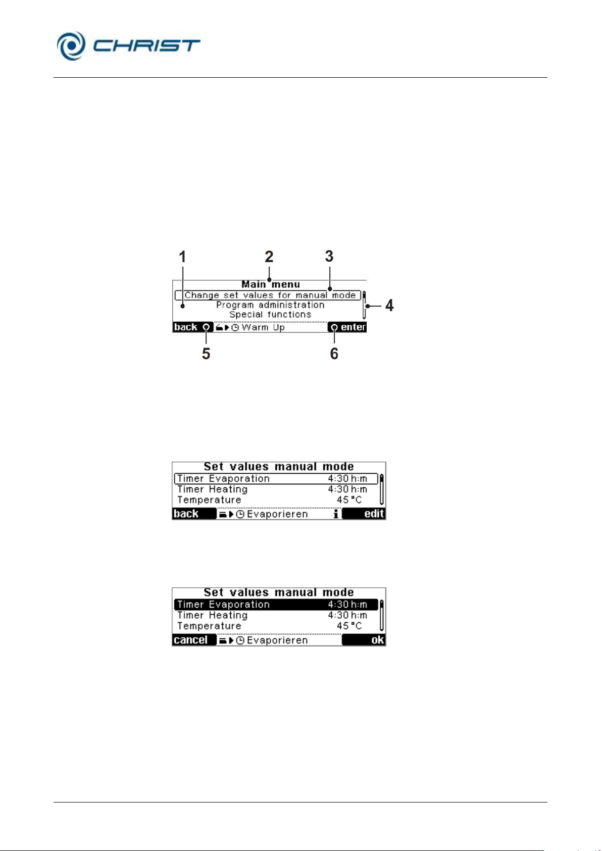
1 Menu list
2 Menu title
3 Focus
4 Scrollbar
5 Function key
"Quit menu"
6 Function key
"Open menu"
6.5.3 Main menu
The main menu can be activated by pressing the right-hand function key
"menu" in the active values window. It contains the following items:
• Changing the set values for the manual mode (see chapter 6.5.3.1 "Changing the set values for the manual mode ")
• Program administration (see chapter 6.5.3.2 - "Program administration")
• Special functions (see chapter 6.5.3.3 - "Special functions")
• Process- & equipment information system (see chapter 6.5.3.4 -
"Process and equipment information")
6.5.3.1 Changing the set values for the manual mode
• Options (see chapter 6.5.3.5 - "Options")
Fig. 28: Structure of the main menu
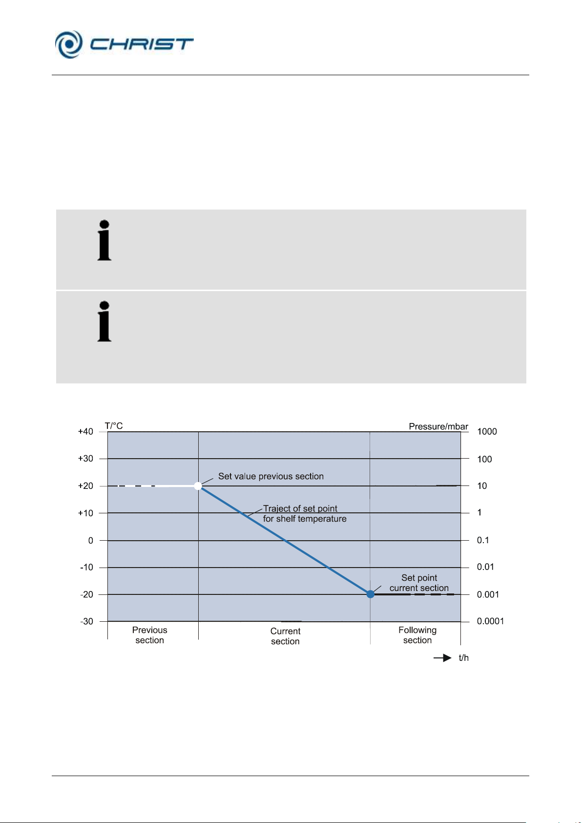
• Select the set value with the up and down keys. The selected value is
displayed in a focus.
Fig. 29: Manual mode – selecting a set value
• Press the right-hand function key to start the editing mode. The focus is
Fig. 30: The selected set value is displayed in an inverted manner
• Change the set value with the up/down keys.
• Press the right-hand function key "ok" to confirm.
The set value is edited. The Evaporation manual process is controlled by
the following set values.
displayed in an inverted manner.
Page 44

Rotational Vacuum Concentrator RVC 2-33 CDplus
with infrared heating
6 Operation
44 / 88
Version 08/2009, Rev. 3.3 of 03/07/2016 • sb
Translation of the original operating manual
NOTE
Because the RVC has no active cooling, it is not possible to reach
temperatures below room temperature. Under certain conditions (e.g. if a
frozen product is loaded) it may be reasonable to choose a temperature
below room temperature.
Timer Evaporation
The time can be set between 1 minute and 200 hours. Using the down key
as of the time 00:01 h:m the symbol appears. The timer is deactivated
and the RVC operates continuously.
Timer Heating
The value that is set under “Timer Evaporation” is also used for “Timer
Heating”.
For some evaporation processes, however, it makes sense to reduce the
heating time. In this case, the value “Timer Heating” can be changed. The
value “Timer Heating” is always lower or equal to the value “Timer
Evaporation”.
Temperature
The control temperature can be set between –80°C and +80°C.
Vacuum (only if a vacuum sensor is installed)
This set value determines the vacuum in the rotor chamber. The value
range is defined from 1,000 mbar to 0.1 mbar.
Safety pressure (only if a vacuum sensor is installed)
When reaching the value of the safety pressure, the heater for
controlling the temperature of the bucket is started. The heat is supplied as
long as the set value of the saftety pressure is not exceeded. If the value of
the safety pressure increases beyond the maximum limit, the heater will be
switched off.
The set value of the safety pressure is defined at a value range from 1,000
mbar to 0.1 mbar.
• In the case of a set vacuum between 1 and 100 mbar, the set value of
the safety pressure should be 5 mbar higher.
• In the case of a set vacuum between 100 and 1,000 mbar, the set value
of the safety pressure should be 10 mbar above the set vacuum.
Alarm temperature (only for RVC 2-33 CDplus with infrared heating)
The product temperature enables conclusions to be drawn concerning the
end of the drying phase: When the medium has evaporated, the product
sensor will no longer be cooled. As a result, the product temperature rises.
Depending on the temperature sensitivity of the product, it may be useful to
define a limit value, at which the heater will be switched off, via the alarm
temperature. When selecting the limit value, it must be taken into
consideration that the energy, which has already been supplied to the
system (e.g. thermal energy from the rotor and rotor chamber), continues to
heat the product even after the heater has been switched off.
The value range of the alarm temperature is between -20°C and +60°C.
Page 45
Rotational Vacuum Concentrator RVC 2-33 CDplus
with infrared heating
6 Operation
Version 08/2009, Rev. 3.3 of 03/07/2016 • sb
45 / 88
Translation of the original operating manual
NOTE
The higher the speed is, the more thermal energy will be produced
because of the waste heat of the drive unit and also because of the eddy
current losses of the magnetic coupling. If thermosensitive products are
processed, the speed can be set to a correspondingly low level in order to
prevent a too high energy input and, thereby, the excessive heating of the
product.
NOTE
If the temperature increases too quickly during an evaporation process, the
system is being supplied with too much energy. As a result, the vacuum
may collapse, which in turn will interrupt the evaporation process and may
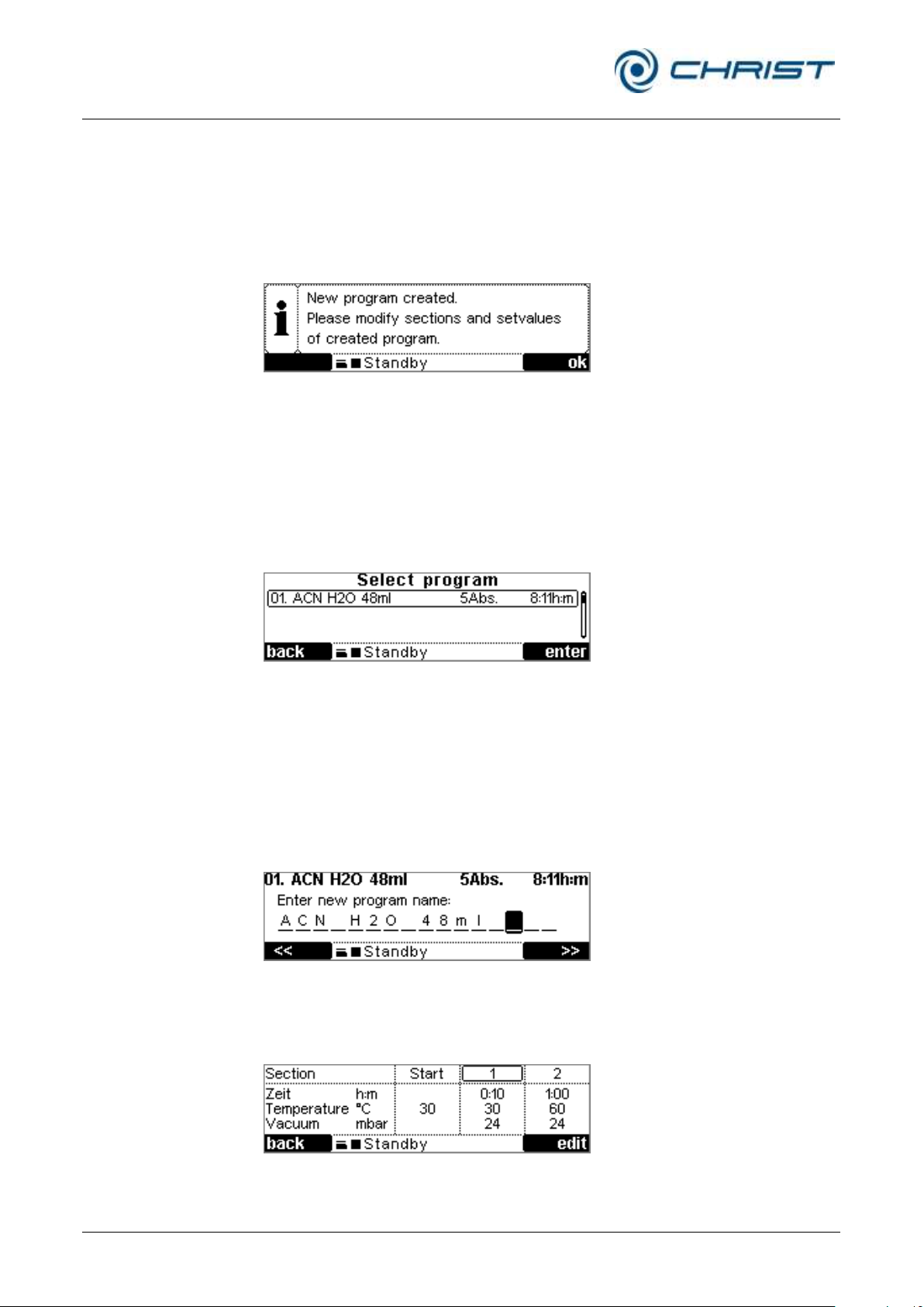
destroy the product in the unit. In order to ensure a controlled process run,
there is no sudden increase or decrease of the setpoint between the
sections. Instead, the setpoint changes steadily. The defined section
setpoint is reached at the end of the respective section.
6.5.3.2 Program administration
Contrary to a manual evaporation process, a program is used for a timercontrolled, pre-programmed process (evaporation program).
An evaporation program is divided into several sections. Every section of
the program has set values for the time, temperature, vacuum, safety
pressure, and speed.
You can create up to 16 individual evaporation programs. Up to 80 sections
can be assigned to each of these programs. A program always consists of
at least 3 sections.
Calculation of the gradient see chapter 11.1 - "Mathematical relations".
Fig. 31: Graphical representation of the course of the control setpoint
Page 46
Rotational Vacuum Concentrator RVC 2-33 CDplus
with infrared heating
6 Operation
46 / 88
Version 08/2009, Rev. 3.3 of 03/07/2016 • sb
Translation of the original operating manual
Creating a new program
A new program can be created based on a fixed program template and
adapted to specific needs by changing the set values and by adding and
deleting certain sections. The control system automatically assigns a
program number to every new program.
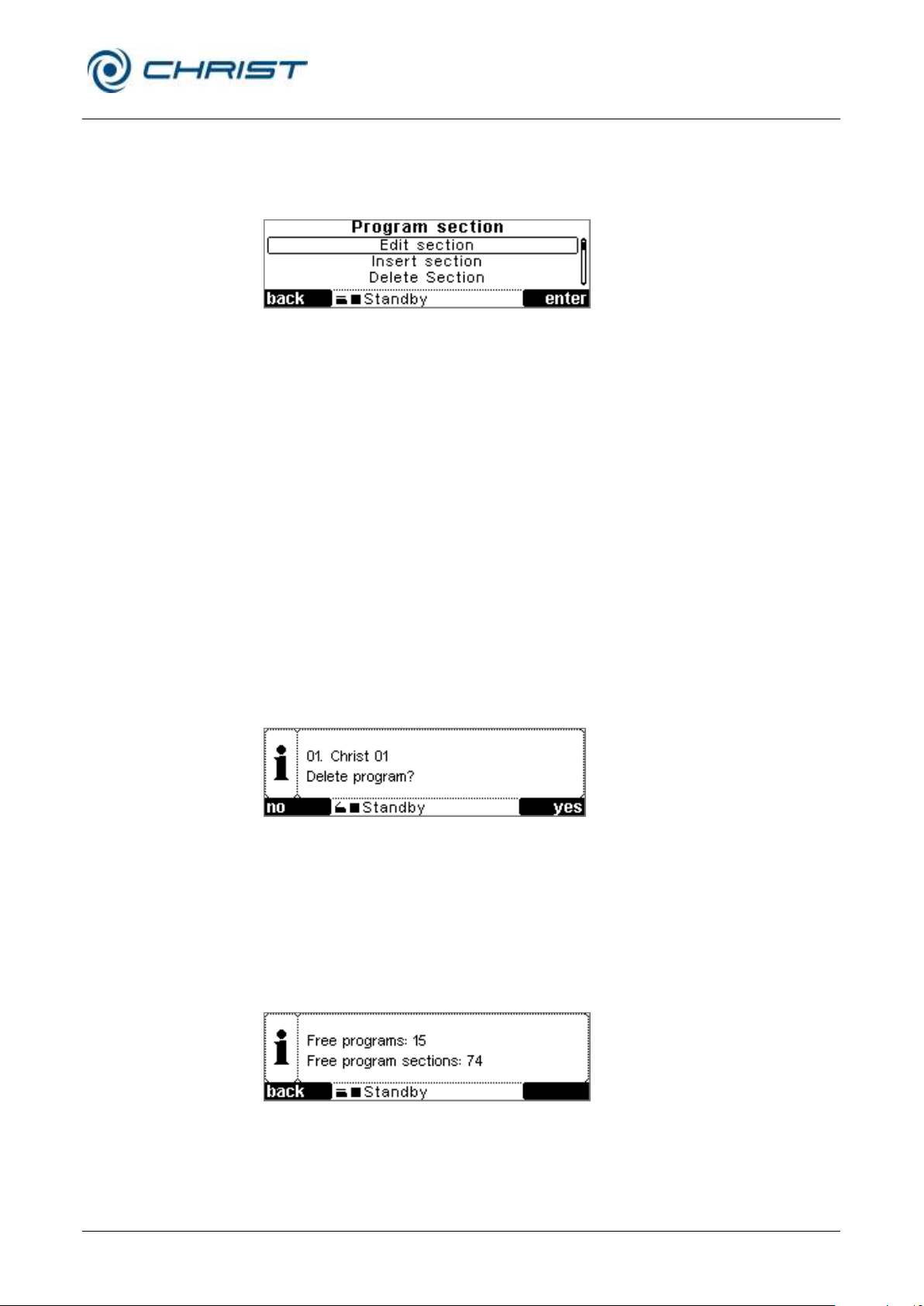
• Select "New program" from the menu "Program administration" (see
figure) and confirm. The following message will appear:
Fig. 32: Message "New program created"
• Press the right-hand function key to confirm.
• Continue as described under "Editing a program" (see below).
Editing a program
• Select "Edit program" from the menu "Program administration" (see
figure) and confirm. The program list is shown.
Fig. 33: Program list
• Select a program from the program list.It will be opened for editing.
• Open the menu "Program parameter" in order to change the program
name. Use the functions keys to position the focus in the program
name. Use the up/down keys to change the character at the current
focus position.
• At the last position of the program name, the right-hand key function
changes to "ok" to enter the program name.
Fig. 34: Changing the program name
The sections of a program can be adapted under "Edit program sections".
The set values and sections are displayed in a tabular form.
Fig. 35: Program section table
Page 47
Rotational Vacuum Concentrator RVC 2-33 CDplus
with infrared heating
6 Operation
Version 08/2009, Rev. 3.3 of 03/07/2016 • sb
47 / 88
Translation of the original operating manual
• Use the up/down keys to scroll through the sections. The section to be
edited is in the middle column of the table.
• Press the right-hand function key "edit" to confirm. The editing menu is
displayed.
Fig. 36: Program section menu
• In this menu, the set values of the selected section can be changed, the
selected section can be deleted, or a new section can be added to the
selected section.
• Confirm the input and quit the menu.
Copying a program
• Select "Copy program" from the program administration menu and
confirm. The program list will be displayed.
• Select a program and confirm. A copy of the selected program will be
created in a free program location.
Deleting a program
• Select "Delete program" from the program administration menu and
confirm.
• Select a program from the program list and confirm. A message will be
displayed:
Abb. 37: Message for deleting a program
• Confirm the message and quit the menu.
Program memory informationen
• Select "Program memory information" from the program administration
Fig. 38: Program memory information
menu and confirm. Information concerning free program locations and
sections are displayed:
Page 48
Rotational Vacuum Concentrator RVC 2-33 CDplus
with infrared heating
6 Operation
48 / 88
Version 08/2009, Rev. 3.3 of 03/07/2016 • sb
Translation of the original operating manual
NOTE
The pressure increase test can only be performed if a vacuum sensor is
installed.
6.5.3.3 Special functions
Pressure increase test
Entering the set values
• Select "Special functions" from the main menu.
• Open the menu "Pressure increase test" and select "Parameter
pressure increase test".
• Enter the set values, confirm and quit the menu.
Performing the pressure increase test
• Select "Special functions" from the main menu.
• Open the menu "Pressure increase test" and select "Start pressure
increase test".
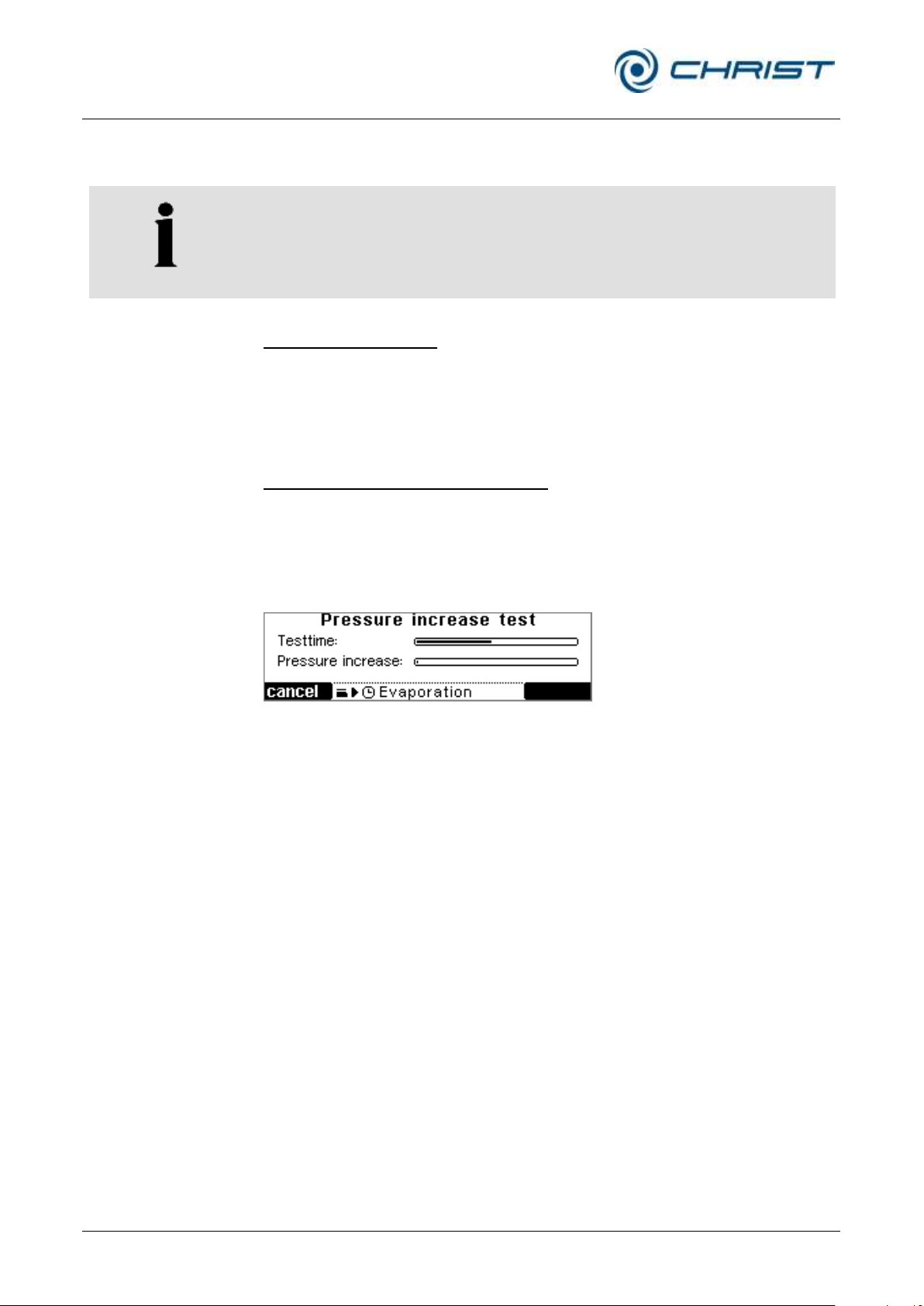
The pressure increase test will be performed. The test time progress and
the measured pressure increase are displayed in a graphical form.
Fig. 39: Graphical presentation of the pressure increase test
When the test is finished, an information window pops up and shows the
result of the pressure increase test.
Page 49
Rotational Vacuum Concentrator RVC 2-33 CDplus
with infrared heating
6 Operation
Version 08/2009, Rev. 3.3 of 03/07/2016 • sb
49 / 88
Translation of the original operating manual
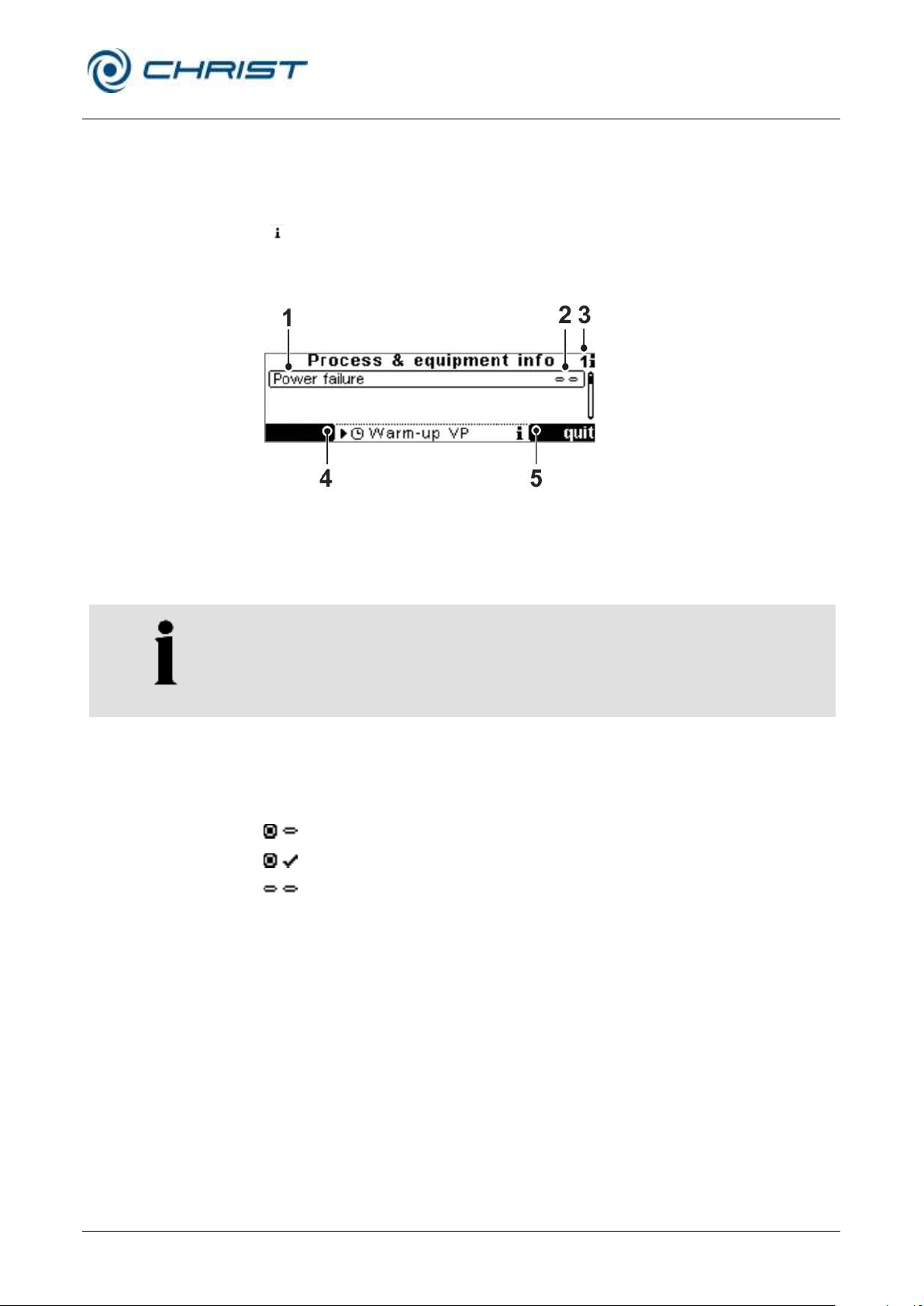
1 Message
2 Status of the
Information
3 Number of messages
pending
4 Function key for
quitting the menu
5 Function key for
acknowledging the
message
NOTE
A detailed list of all messages can be found in chapter 7 "Malfunctions and
error correction".
Information present, not acknowledged
Information present, acknowledged
Error no longer present, information not acknowledged
6.5.3.4 Process and equipment information
The "Process & equipment Information " menu informs the user about any
error, process, or system messages.
In the event of a message, a sound signal can be heard and the symbol
" " is displayed on the status bar. In addition, the process and equipment
information is displayed. If the user is in a menu, the window will not be
displayed until the user quits the main menu.
Fig. 40: Structure of the process & equipment info window
In addition, the menu can be opened at any time to check whether any
messages are pending.
Information status
Every piece of information shown in the process & equipment information
window receives a certain status:
The sound signal continues until all the information is acknowledged.
Once some information is no longer present but has been acknowledged,
the information will be removed from the process & equipment information
window.
In order to quit the process & equipment information window, you have to
acknowledge all of the pieces of information so that the left-hand function
key "back" can be displayed.
Page 50
Rotational Vacuum Concentrator RVC 2-33 CDplus
with infrared heating
6 Operation
50 / 88
Version 08/2009, Rev. 3.3 of 03/07/2016 • sb
Translation of the original operating manual
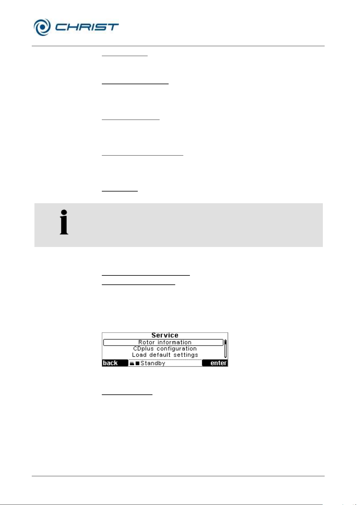
6.5.3.5 Options
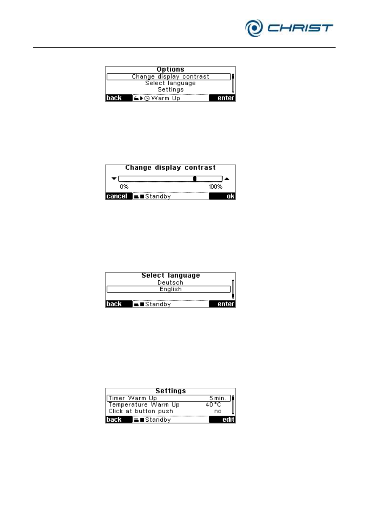
Fig. 41: Menu “Options”
Change display conrast
• Select the menu "Change display contrast".
• Change the contrast by pressing the up/down keys.
• Confirm the new setting by pressing the right-hand function key.
Fig. 42: Changing the contrast
Select language
The CDplus control system can be used in German or English.
• Select the menu "Select language".
• Select the language using the up/down keys.
• Confirm the input by pressing the right-hand function key.
Fig. 43: Selecting a language
Settings
The Settings menu is used to customise the operation and process
management of the control system.
• Select the value you want to set.
• Change the value using the up/down keys.
• Confirm the input by pressing the right-hand function key.
Fig. 44: Settings menu
Page 51
Rotational Vacuum Concentrator RVC 2-33 CDplus
with infrared heating
6 Operation
Version 08/2009, Rev. 3.3 of 03/07/2016 • sb
51 / 88
Translation of the original operating manual
NOTE
We guarantee that a speed of 1,350 rpm can be reached with all of the
available rotors. Higher speeds are possible in individual cases.
Timer Warm-up
You can set a warm-up time between 5 and 99 minutes.
Temperature Warm-up
During the warm-up phase, the rotor temperature is set to the set
temperature.
Click at button push
If this function is activated, a brief sound signal can be heard whenever a
key is pressed.
High temperature resolution
Temperatures are displayed in the values window with a resolution of
1
/10°C, normally with a resolution of 1°C.
Rotor speed
The rotor speed can be set in a range between 100 rpm and 1,750 rpm.
Continuous operation coldtrap (only if a cold trap is installed) and
Continuous operation VP
If these options are set to "yes", the vacuum pump and the cold trap will not
be switched off after the evaporation. Instead, they will remain active. This
is useful if several evaporation processes are started in succession.
Service menu
Fig. 45: Service menu
Rotor information
This function is not supported by this type of unit.
Page 52

Rotational Vacuum Concentrator RVC 2-33 CDplus
with infrared heating
6 Operation
52 / 88
Version 08/2009, Rev. 3.3 of 03/07/2016 • sb
Translation of the original operating manual
NOTE
• If an option is installed, it has to be activated with "yes".
• If the option is not installed, it has to be deactivated with “no”.
CDplus configuration
In this menu, accessories (options) have to be configured:
• VaCuum sensor
• Remote control cold trap
• Air injection
• Triple TMM (not available for all RVC types)
• Imbalance detection (not available for all RVC types)
Load default settings
All set values and parameters are reset to the delivery status of the RVC.
The reset requires confirmation.
Extended service menu
The extended service menu is exclusively reserved for service engineers.
This area is password-protected and not available to the user.
Page 53

Rotational Vacuum Concentrator RVC 2-33 CDplus
with infrared heating
7 Malfunctions and error correction
Version 08/2009, Rev. 3.3 of 03/07/2016 • sb
53 / 88
Translation of the original operating manual
Error
Possible reason
Correction
No vacuum sensor signal
• The control unit receives an
invalid value from the vacuum
sensor.
• Check the connecting cables
and plug-in connections of the
vacuum sensor. If necessary,
replace the vacuum sensor.
No rotor chamber sensor signal
• The temperature sensor of the
rotor chamber is disconnected
or defective
• Contact the after-sales service
(see chapter 7.2 - "Service
contact")
No rotor sensor signal
• The rotor temperature sensor is
disconnected or defective
• Contact the after-sales service
(see chapter 7.2 - "Service
contact")
No ice condenser sensor signal
• The data communication link to
the cooling trap is interrupted,
or the ice condenser
temperature sensor is
disconnected or defective
• Check the data link between the
rotational vacuum concentrator
and the cooling trap
Lid cannot be opened
• The rotor chamber is not
aerated completely
• Aerate the rotor chamber
completely
Lid contacts error
• The system has detected an
open lid during evaporation.
The rotor will be stopped
immediately. The lid must be
closed while the rotor is moving.
• Check the lid contacts. If
necessary, contact the aftersales service (see chapter 7.2 "Service contact")
Rotor overtemperature
• The maximum permissible rotor
temperature of 85°C has been
exceeded
• If the system does not cool
down, disconnect it immediately
from the power supply. Contact
the after-sales service (see
chapter 7.2 - "Service contact")
Chamber overtemperature
• The maximum permissible
chamber temperature has been
exceeded
• If the system does not cool
down, disconnect it immediately
from the power supply. Contact
the after-sales service (see
chapter 7.2 - "Service contact")
7 Malfunctions and error correction
7.1 General malfunctions
7.1.1 Error messages
Malfunctions are displayed in the menu "Process & equipment info" (see
chapter 6.5.3.4 - "Process and equipment information"). A sound signal
sounds when an error message is generated.
• Eliminate the source of the problem (see the following chapters).
• Acknowledge the error messages by pressing the right-hand function
key.
Page 54

Rotational Vacuum Concentrator RVC 2-33 CDplus
with infrared heating
7 Malfunctions and error correction
54 / 88
Version 08/2009, Rev. 3.3 of 03/07/2016 • sb
Translation of the original operating manual
Error
Possible reason
Correction
Permissible imbalance exceeded
• The rotor will be stopped
immediately, the process will
also be stopped.
– improper loading of the
rotor
– glass breakage
– uneven evaporation
• Balance the load and restart the
rotational vacuum concentrator.
If the error occurs again, contact
the after-sales service (see
chapter 7.2 - "Service contact")
VSK3000 calibration error
• Incorrect calibration of the
vacuum sensor VSK3000
• The sensor must be recalibrated
(see separate operating manual)
Error
Possible reason
Correction
Mains power failure
• A mains power failure will be
detected if the power supply is
interrupted under normal
conditions (run mode).
• The process will continue once
the mains power is available
again. The process times will be
reset to zero. The set control
values will be preserved.
Factory settings loaded
• All parameters are reset to the
delivery status of the system.
• The factory settings will be
loaded if the corresponding
menu command is executed in
the service menu or if an error
occurred in the parameter menu.
No rotor detected (only Triple TMM)
• Check the rotor for correct
installation.
• If the error occurs again, contact
the after-sales service (see
chapter 7.2 - "Service contact").
Nominal rotor speed not reached
• After two minutes, the rotor has
still not reached 90% of its
nominal speed.
– set speed is too high
– drive moves sluggishly
• Check the set speed.
• When the rotor is at a standstill
and the system is switched off,
check whether the drive moves
sluggishly, by hand. Contact the
after-sales service (see chapter
7.2 - "Service contact").
Safety pressure not reached
• The safety pressure inside the
rotor chamber must be reached
within 5 minutes after the start
of an evaporation process.
• Check whether the value that
was entered for the safety
pressure is not too low.
• Check the components for any
possible leaks.
Ice condenser temperature not
reached
• Only if the "Cooling trap control"
option is enabled:
The ice condenser temperature
must be -25°C.
• If the temperature is not
reached, the heater will be
deactivated.
7.1.2 Process messages
Page 55

Rotational Vacuum Concentrator RVC 2-33 CDplus
with infrared heating
7 Malfunctions and error correction
Version 08/2009, Rev. 3.3 of 03/07/2016 • sb
55 / 88
Translation of the original operating manual
Error
Possible reason
Correction
Invalid system type
• Contact the after-sales service
(see chapter 7.2 - "Service
contact").
IO communication error 0x21
• Failure of the CDplus IO module
• Switch the system off and then
on again. If the error occurs
again, contact the after-sales
service (see chapter 7.2 "Service contact")
IO communication error 0x30
• Failure of the reading unit of the
electronic rotor system
• Switch the system off and then
on again. If the error occurs
again, contact the after-sales
service (see chapter 7.2 "Service contact")
IO communication error 0x40
• Failure of the motor control
system
• Switch the system off and then
on again. If the error occurs
again, contact the after-sales
service (see chapter 7.2 "Service contact")
IO communication error 0x41
• Failure of the imbalance
detection module
• Switch the system off and then
on again. If the error occurs
again, contact the after-sales
service (see chapter 7.2 "Service contact")
WARNING
• Do not actuate the emergency lid release before the rotor has stopped
and the pressure has been relieved.
• Do not use the emergency lid release to open the lid during normal
operation. Unlocked lid locks increase the risk of accidents!
7.1.3 System messages
7.1.4 Emergency lid release
In the event of a power failure, it is possible to manually open the lid of the
rotational vacuum concentrator.
• Switch off the mains power switch and disconnect the power cord from
the socket.
• Check if the rotor is at a standstill and the rotor chamber is completely
aerated.
• Pull the unit a bit over the edge of the table and jack it up (see the
illustration below). Ensure that the centre of gravity of the unit is still on
the table. If necessary, the unit must be secured by a second person.
Page 56
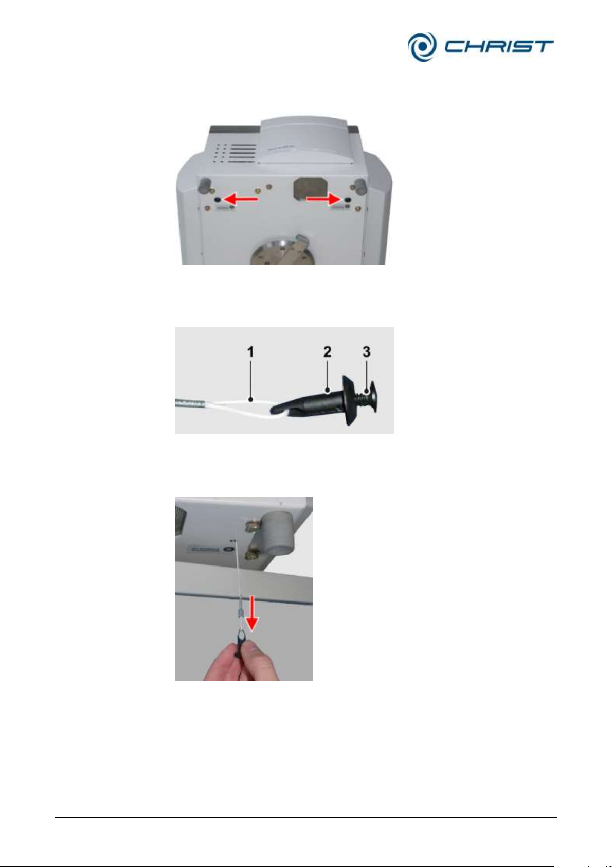
Rotational Vacuum Concentrator RVC 2-33 CDplus
with infrared heating
7 Malfunctions and error correction
56 / 88
Version 08/2009, Rev. 3.3 of 03/07/2016 • sb
Translation of the original operating manual
1 Release string
2 Stopper
3 Plastic screw
• Unscrew the two black plastic screws (approx. 8 mm).
Fig. 46: Position of the plastic screws of the emergency lid release
• Remove the stoppers, e.g. with a screwdriver. The stoppers are
connected to a mechanical release string (see the illustration below).
Fig. 47: Release string with stopper and screw
• Pull the stoppers with their strings vertically downwards until the lid
locks unlock. Unlock the right and left lock in this way.
Fig. 48: Unlocking the lid locks
• Open the lid.
• After the emergency lid release has been used, reinstall both stoppers
and strings in the reversed order.
• Try to locate the error source and contact the service if necessary.
Page 57
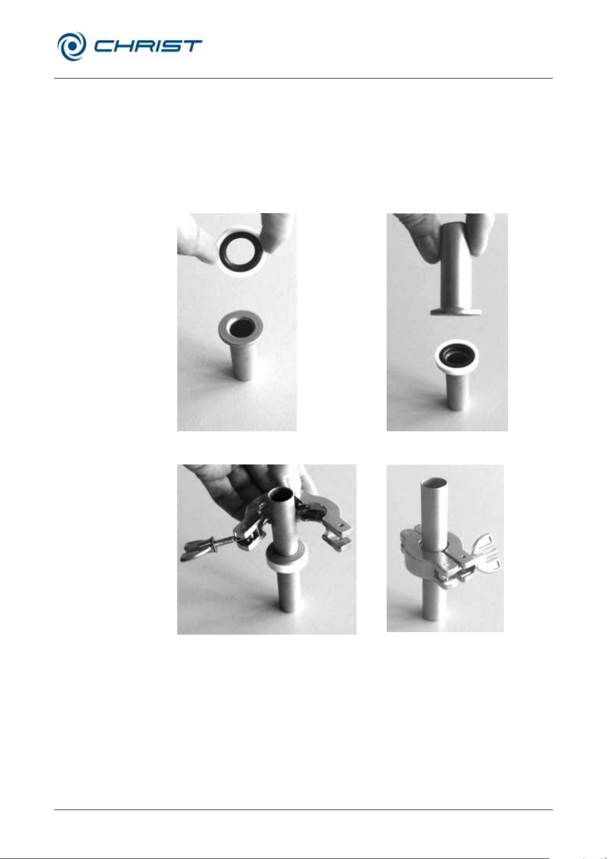
Rotational Vacuum Concentrator RVC 2-33 CDplus
with infrared heating
7 Malfunctions and error correction
Version 08/2009, Rev. 3.3 of 03/07/2016 • sb
57 / 88
Translation of the original operating manual
Fig. 49: Small flange and centring ring
Fig. 50: Small flange with centring ring
and small flange
Fig. 51: Attaching the clamping ring
Fig. 52: Tightened clamping ring
7.1.5 Small flange connections
Leakages are often due to improper small flange connections between the
various components and hose connections or to leakages in the valves.
• Loosen the connection and place the centring ring (with sealing ring
inside) in a centred manner between the flange connections.
• Seal the connection with the clamping ring or clamping chain by
tightening the wing nut.
• Ensure that the centring ring neither slips out of place nor gets jammed.
Page 58

Rotational Vacuum Concentrator RVC 2-33 CDplus
with infrared heating
7 Malfunctions and error correction
58 / 88
Version 08/2009, Rev. 3.3 of 03/07/2016 • sb
Translation of the original operating manual
NOTE
If you would like to utilise our after-sales-service, please state the type of
your RVC and its serial number.
7.2 Service contact
In the event of queries, malfunctions, or spare part enquiries:
From Germany:
Contact
Martin Christ Gefriertrocknungsanlagen GmbH
An der Unteren Söse 50
37520 Osterode (Germany)
Tel. +49 (0) 55 22 / 50 07-44 44
E-mail: [email protected]
Outside Germany:
Contact our agency in your country. All agencies are listed at
www.martinchrist.de [Sales Partners]
Page 59

Rotational Vacuum Concentrator RVC 2-33 CDplus
with infrared heating
8 Maintenance and service
Version 08/2009, Rev. 3.3 of 03/07/2016 • sb
59 / 88
Translation of the original operating manual
CAUTION
If corrosion or other damage occurs due to improper care, the
manufacturer cannot be held liable or subject to any warranty claims.
WARNING
Take suitable precautions for your own safety if there is a risk of toxic,
radioactive, or pathogenic contamination.
8 Maintenance and service
The rotational vacuum concentrator and the accessories are subject to high
mechanical stress. Thorough maintenance performed by the user extends
the service life and prevents premature failure.
• Use soap water or other water-soluble, mild cleaning agents for
cleaning the RVC and the accessories.
• Do not use any corrosive or aggressive substances.
• Do not use solvents.
• Do not use agents with abrasive particles.
• Do not expose the RVC or its accessories to intensive UV radiation (e.g.
sunlight) or thermal stress (e.g. by heat generators).
8.1 Maintenance
8.1.1 Rotational vacuum concentrator
• Switch off the rotational vacuum concentrator via the mains power
switch and disconnect the power cord before cleaning.
• Carefully remove all product residues from the rotor chamber using a
cloth.
• If the rotational vacuum concentrator has been contaminated with toxic,
radioactive, or pathogenic substances, clean the rotor chamber
immediately with a suitable decontamination agent (depending on the
type of contamination).
• Check the safety guard of the fan (at the front of the bottom side) at
least once a year for dirt and clean it if necessary (e.g. with a vacuum
cleaner).
• Open the rotational vacuum concentrator when it is not in use so that
moisture can evaporate.
Page 60
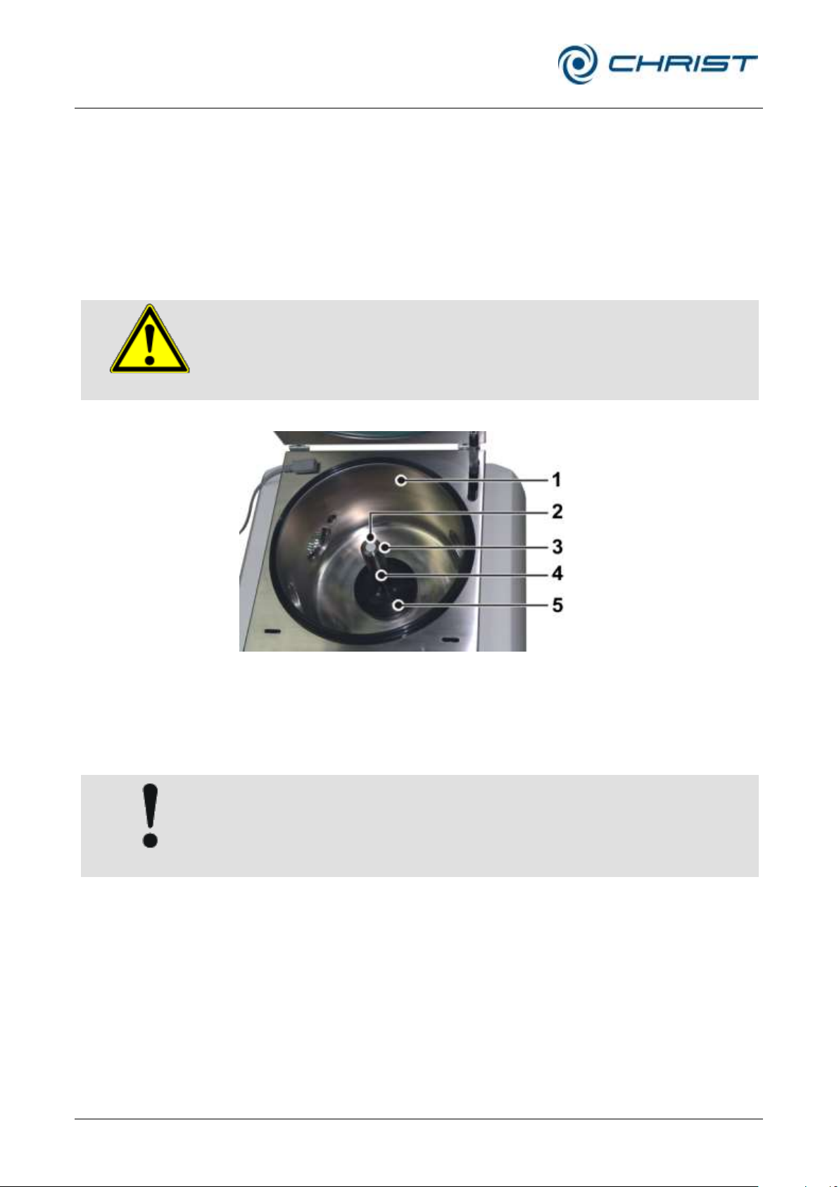
Rotational Vacuum Concentrator RVC 2-33 CDplus
with infrared heating
8 Maintenance and service
60 / 88
Version 08/2009, Rev. 3.3 of 03/07/2016 • sb
Translation of the original operating manual
DANGER
Hot surface!
Let the rotor chamber cool down to room temperature!
1 Rotor chamber
2 Electronic
temperature
measurement system
of the shaft
3 Cap
4 Rotor shaft
5 Magnetic coupling on
rotor side
CAUTION
The rotational vacuum concentrator weighs approx. 49 kg!
8.1.2 Rotor chamber
If the rotor chamber is contaminated or if glass is broken, the rotor
chamber, the rotor shaft and the rotor must be cleaned immediately in order
to prevent corrosion.
Removing the rotor shaft and the magnet coupling on rotor side
• Open the lid.
• Disconnect the power cord from the wall outlet or instrument receptacle.
Fig. 53: Rotor chamber with rotor shaft incl. magnet coupling
• To get access to the bottom of the unit, turn the unit upside down or
place the unit between two trestles or two tables with a sufficient
number of people helping you.
Page 61
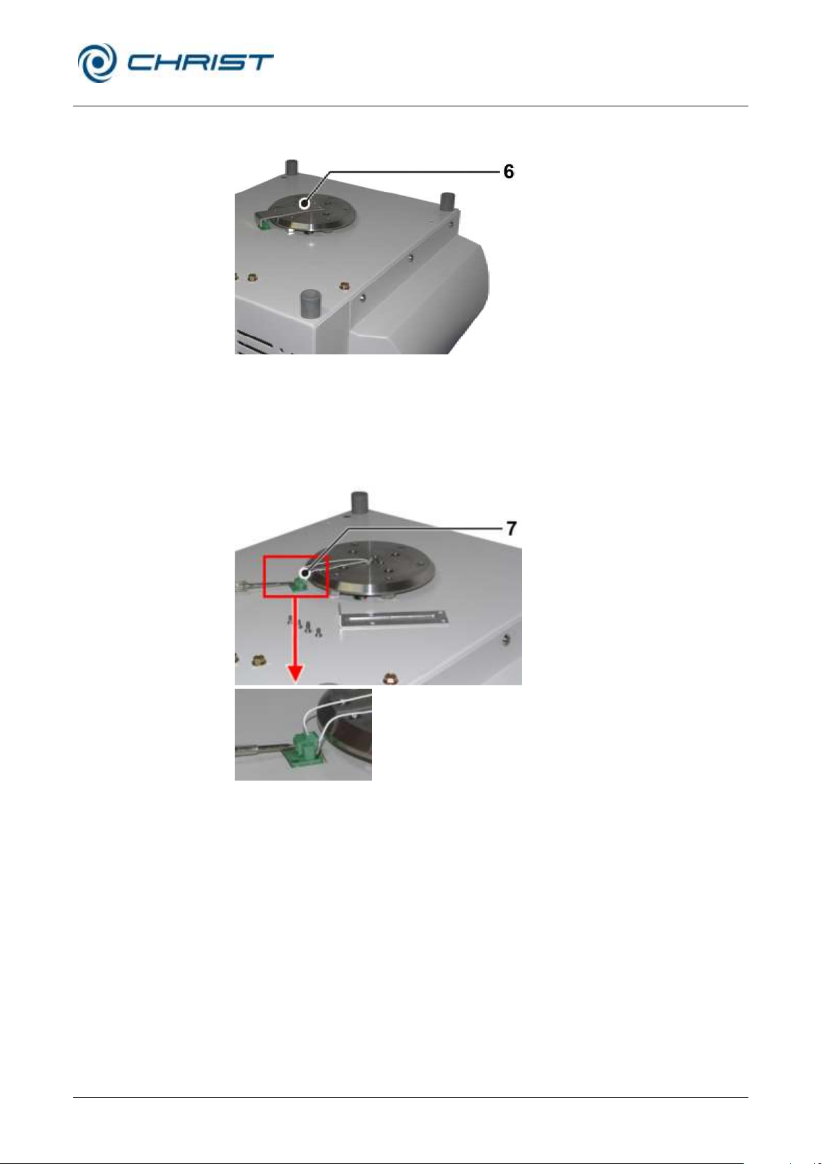
Rotational Vacuum Concentrator RVC 2-33 CDplus
with infrared heating
8 Maintenance and service
Version 08/2009, Rev. 3.3 of 03/07/2016 • sb
61 / 88
Translation of the original operating manual
6 Cable cover
7 Terminal screws
• Remove the cable cover at the bottom of the unit.
Fig. 54: Removing the cable cover at the bottom of the unit
The cables of the electronic temperature measurement system of the shaft
can be seen now.
• Unscrew the two terminal screws of the electronic temperature
measurement system of the shaft.
Fig. 55: Removing the terminal screws of the electronic temperature measurement system
• Turn the rotational vacuum concentrator back to its normal position
(with a sufficient number of people helping you), if it was turned upside
down.
Page 62
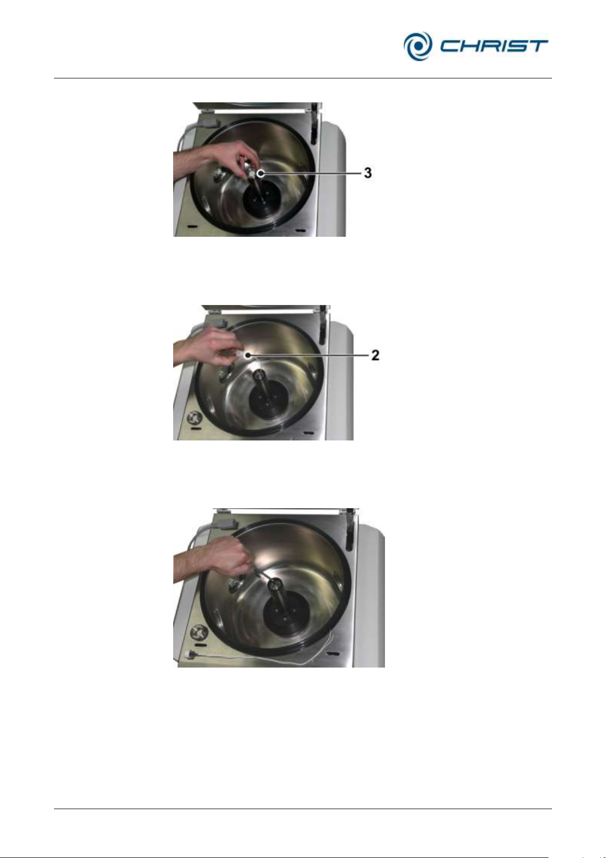
Rotational Vacuum Concentrator RVC 2-33 CDplus
with infrared heating
8 Maintenance and service
62 / 88
Version 08/2009, Rev. 3.3 of 03/07/2016 • sb
Translation of the original operating manual
• Remove the cap.
Fig. 56: Removing the cap
• Screw out the electronic temperature measurement system of the
shaft. Pay attention to the corresponding cables.
Fig. 57: Removing the electronic temperature measurement system
• Loosen the rotor shaft incl. magnetic coupling using the hexagon socket
wrench (size 5).
Fig. 58: Loosening the rotor shaft incl. magnetic coupling
Page 63
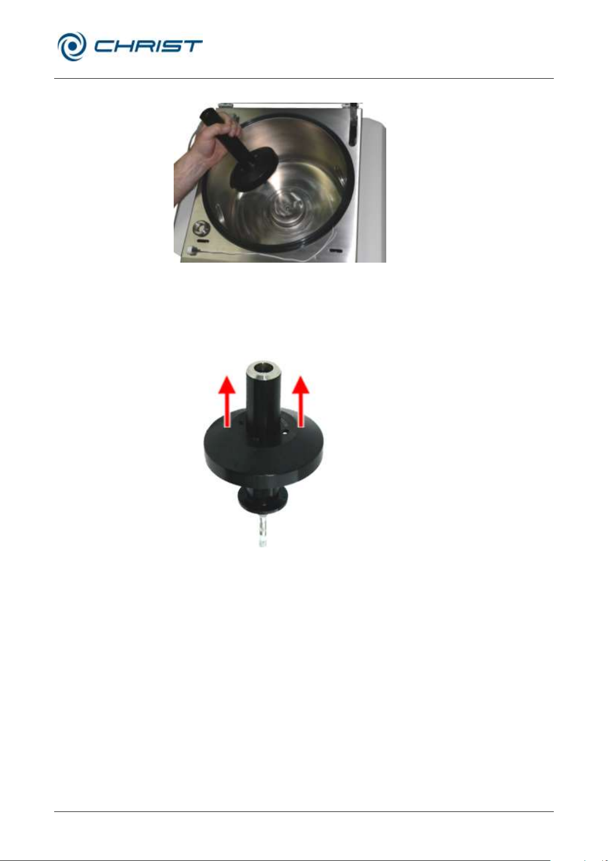
Rotational Vacuum Concentrator RVC 2-33 CDplus
with infrared heating
8 Maintenance and service
Version 08/2009, Rev. 3.3 of 03/07/2016 • sb
63 / 88
Translation of the original operating manual
• Remove the rotor shaft incl. magnet coupling.
Fig. 59: Removing the rotor shaft incl. magnet coupling
• Remove the four fastening screws on the upper side of the magnetic
coupling using the L-key Torx TX15.
• Remove the magnetic coupling from the rotor shaft.
Fig. 60: Removal of the magnet coupling on rotor side
Page 64
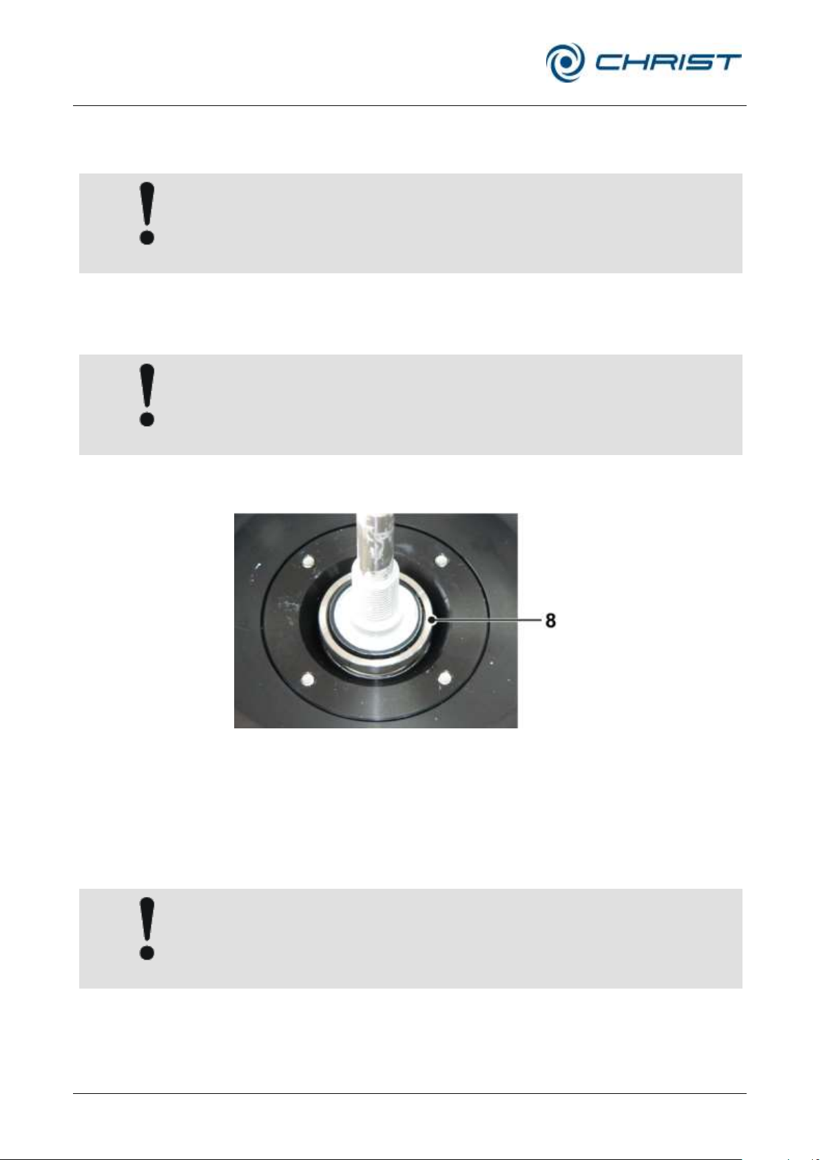
Rotational Vacuum Concentrator RVC 2-33 CDplus
with infrared heating
8 Maintenance and service
64 / 88
Version 08/2009, Rev. 3.3 of 03/07/2016 • sb
Translation of the original operating manual
CAUTION
Ensure that no cleaning agent or disinfectant gets into the opening at the
bottom of the rotor chamber.
This can lead to irreparable damage at the motor.
CAUTION
When installing the rotor shaft, ensure that the O-ring used to seal the
rotor chamber is fitted correctly.
8 O-Ring of the rotor
shaft
CAUTION
For the care of the accessories, special safety measures must be
considered as these are measures that will ensure operational safety at
the same time.
Installation of the rotor shaft and the magnet coupling on rotor side
• Clean the rotor chamber, the rotor shaft and the magnet coupling with
cleaning agent or a disinfectant.
• Clean the cap and grease the O-ring of the cap slightly with vacuum
grease.
• Install the components or assemblies in a reversed order.
• Grease the O-ring with vacuum grease to ensure that it does not get out
of place.
Fig. 61: O-ring at the bottom of the rotor shaft
• Plug in the mains plug and switch the rotational vacuum concentrator
on.
• Perform a test run.
8.1.3 Accessories
Chemical reactions as well as stress-corrosion (combination of oscillating
pressure and chemical reaction) can affect or destroy the metals. Barely
detectable cracks on the surface can expand and weaken the material
without any visible signs.
Page 65

Rotational Vacuum Concentrator RVC 2-33 CDplus
with infrared heating
8 Maintenance and service
Version 08/2009, Rev. 3.3 of 03/07/2016 • sb
65 / 88
Translation of the original operating manual
CAUTION
In the case of glass breakage, immediately remove all glass particles (e.g.
with a vacuum cleaner). Replace the rubber cushions since even thorough
cleaning will not remove all glass particles.
• Check the material regularly (at least once a month) for
– cracks
– visible damage of the surface
– pressure marks
– signs of corrosion
– other changes.
• Replace any damaged components immediately for your own safety.
• Immediately rinse off the rotors or accessories if any liquids that may
cause corrosion come into contact with them.
• Clean the accessories outside the rotational vacuum concentrator once
a week or preferably after each use.
• If the rotors or accessories have been contaminated with toxic,
radioactive, or pathogenic substances, clean them immediately with a
suitable decontamination agent (depending on the type of
contamination). Take suitable precautions for your own safety if there is
a risk of toxic, radioactive, or pathogenic contamination.
8.1.3.1 Aluminium accessories
Especially aluminium parts are susceptible to corrosion.
• Acid-containing cleaning agents and alkaline cleaning agents must be
avoided.
• Grease aluminium parts at least once a week with slushing oil for the
protection against corrosion.
This essentially increases their service life and reduces susceptibility to
corrosion.
8.1.4 Glass breakage
Glass particles will damage the surface coating (e.g. anodising) of the
buckets, which will then lead to corrosion.
Glass particles in the rubber cushions of the buckets will cause glass
breakage again.
Glass particles on the pivot bearing of the load- bearing bolts prevent the
buckets and rotor blocks from swinging evenly, which will cause an
imbalance.
Glass particles in the rotor chamber will cause metal abrasion due to the
circulation. This metal dust will not only pollute the rotor chamber, rotor,
and materials to be evaporated but also damage the surfaces of the
accessories, rotors, and rotor chamber.
Page 66

Rotational Vacuum Concentrator RVC 2-33 CDplus
with infrared heating
8 Maintenance and service
66 / 88
Version 08/2009, Rev. 3.3 of 03/07/2016 • sb
Translation of the original operating manual
DANGER
If dangerous materials (e.g. infectious and pathogenic substances) are
used, the RVC and the accessories must be disinfected.
Accessories
Max. temp
[°C]
Min. time
[min]
Max. time
[min]
Max. cycles
Glass tubes
134-138
3
40
-
Polycarbonate tubes
115-118
30
40
20
Polypropylene tubes
115-118
30
40
30
Teflon tubes
134-138
3 5 100
Aluminium rotors
134-138
3
20
-
Aluminium accessories
134-138
3
20
-
In order to completely remove the glass particles and metal dust from
the rotor chamber
• Grease the upper third of the rotor chamber with e.g. Vaseline.
• Then, let the rotor rotate for a few minutes at maximum speed and
atmospheric pressure. The glass and metal particles will now collect at
the greased part.
• Remove the grease with the glass and metal particles with a cloth.
• If necessary, repeat this procedure.
• Clean the rotor shaft.
8.2 Disinfection of the rotor chamber and accessories
• Use commercially-available disinfectants such as, for example, Incidur®,
Meliseptol®, Sagrotan®, Buraton® or Terralin® (available at chemist’s
shops or drugstores).
• The rotational vacuum concentrator and the accessories consist of
various materials. A possible incompatibility must be considered.
• Before using cleaning or decontamination agents that were not
recommended by us, contact the manufacturer to ensure that such a
procedure will not damage the rotational vacuum concentrator.
• For autoclaving, consider the continuous heat resistance of the
individual materials.
• Please contact us if you have any queries (see chapter 8.4 - "Service").
8.3 Autoclaving
The service life of the accessories essentially depends on the frequency of
autoclaving and use.
• Remove the existing O-rings so that the trapezoid notch can be reached
• Replace the accessories immediately when the parts show changes in
by the hot steam. This prevents the formation of humidity in the notch..
colour or structure or in the occurrence of leaks etc.
Page 67

Rotational Vacuum Concentrator RVC 2-33 CDplus
with infrared heating
8 Maintenance and service
Version 08/2009, Rev. 3.3 of 03/07/2016 • sb
67 / 88
Translation of the original operating manual
DANGER
In the event of service work that requires the removal of the panels, there
is a risk of electric shock or mechanical injury. Only qualified specialist
personnel is authorised to perform this service work.
NOTE
If you would like to utilise our service, please state the type of your RVC
and its serial number.
8.4 Service
The rotational vacuum concentrator is subject to high mechanical stress. In
order to be able to withstand this high level of stress, high-quality
components were used during the production of the rotational vacuum
concentrators. Nevertheless, wear cannot be excluded and it may not be
visible from the outside.
This is why we recommend having the rotational vacuum concentrator
checked by the manufacturer during an inspection once per year in the
operating state and once every three years in the dismantled state.
Information and appointments:
In Germany:
Contact
Martin Christ Gefriertrocknungsanlagen GmbH
An der Unteren Söse 50
37520 Osterode
Tel. +49 (0) 55 22 / 50 07-44 44
E-mail: [email protected]
Outside Germany:
• Contact our agency in your country. All agencies are listed at
www.martinchrist.de [Sales Partners]
8.5 Return of defective parts
Although we exercise great care during the production of our products, it
may be necessary to return a unit or accessory to the manufacturer.
In order to ensure the quick and economical processing of returns of
freeze-dryers, rotational vacuum concentrators, spare parts, or
accessories, we require complete and extensive information concerning the
process. Please fill in the following forms completely, sign them, enclose
them with the return package, and send them together with the product to:
Martin Christ Gefriertrocknungsanlagen GmbH
An der Unteren Söse 50
37520 Osterode (Germany)
Page 68
Rotational Vacuum Concentrator RVC 2-33 CDplus
with infrared heating
8 Maintenance and service
68 / 88
Version 08/2009, Rev. 3.3 of 03/07/2016 • sb
Translation of the original operating manual
NOTE
We will return the unit if no declaration of decontamination is provided!
NOTE
The unit must be packaged in a transport-safe manner. Please use the
original packaging, if at all possible.
If the product is dispatched to us in unsuitable packaging, you will be
charged the cost for returning it to you in new packaging.
1. Declaration of decontamination
As a certified company and due to the legal regulations for the
protection of our employees and of the environment, we are obliged to
certify the harmlessness of all incoming goods. For this purpose, we
require a declaration of decontamination.
• The form must be filled in completely and signed by authorised and
specialised personnel only.
• Affix the original form in a clearly visible manner to the outside of the
packaging.
2. Form for the return of defective parts
This form is for the product-related data. They facilitate the assignment,
and they enable the quick processing of the return. If several parts are
returned together in one packaging, please enclose a separate problem
description for every defective part.
• A detailed problem description is necessary in order to perform the
repair quickly and economically.
• Upon request, we will prepare and submit to you a cost estimate
prior to performing the repair. Please confirm such cost estimate
within 14 days. If the cost estimate has still not been confirmed after
4 weeks, we will return the unit. Please note that you must bear the
incurred costs.
The forms can be downloaded online from
www.martinchrist.de [Service] [Overhaul, repair and leak testing].
Page 69

Rotational Vacuum Concentrator RVC 2-33 CDplus
with infrared heating
9 Disposal
Version 08/2009, Rev. 3.3 of 03/07/2016 • sb
69 / 88
Translation of the original operating manual
9 Disposal
9.1 Disposal of the RVC
Martin Christ Gefriertrocknungsanlagen GmbH is a registered manufacturer
of electric and electronic devices that are solely intended for commercial
use.
• Comply with all local rules and regulations.
9.2 Disposal of the packaging
• Dispose of the packaging, after having separated the individual
materials.
• Comply with all local rules and regulations.
Page 70

Rotational Vacuum Concentrator RVC 2-33 CDplus
with infrared heating
10 Technical data
70 / 88
Version 08/2009, Rev. 3.3 of 03/07/2016 • sb
Translation of the original operating manual
Manufacturer:
Martin Christ
Gefriertrocknungsanlagen GmbH
Type:
RVC 2-33 IR
Order number:
101244
Performance data
Temperature:
+30 °C to +80 °C
Speed:
1,750 rpm
Relative centrifugal force:
530 x g
Max. permissible imbalance:
50 g
Max. density of material at process start:
2 kg / dm3
Connection requirements
Electrical connection:
1 x 230 V / 50/60 Hz
Protection class:
I
IP code:
11
Apparent power:
1.5 kVA
Nominal current:
2.5 A
Mains fuse:
6.3 A F
Stop valve connection:
230 V, 50 Hz, 20 W max.
Pressure control valve connection:
230 V, 50 Hz, 20 W max.
Vacuum pump connection:
230 V, 50 Hz, 3,5 A max.
Physical data
Dimension of the unit
Height:
Height with open lid:
Width:
Depth:
315 mm
715 mm
550 mm
520 mm + 20 mm vacuum connection
Dimensions of the rotor chamber
Inside diameter:
Height, inside:
330 mm
222 mm
Max. lid opening angle:
approx. 80°
Weight:
approx. 49 kg
Noise level according to DIN 45635:
49 dB (A)
EMC according to EN 55011:
Class B
10 Technical data
Page 71

Rotational Vacuum Concentrator RVC 2-33 CDplus
with infrared heating
10 Technical data
Version 08/2009, Rev. 3.3 of 03/07/2016 • sb
71 / 88
Translation of the original operating manual
Equipment connections
Vacuum connection:
Small flange connection DN25KF
(ISO 28403, DIN 2861)
Aeration valve:
Hose nozzle, outside diameter 4.5mm max.
(DN2.5)
or with air filter
Micro injection valve:
Hose nozzle, outside diameter 4.5mm max.
(DN2.5)
or with air filter
Mains input:
IEC C13 connector
Stop valve:
IEC C14 connector
Pressure control valve:
IEC C14 connector
Vacuum pump:
IEC C14 connector
Vacuum sensor:
M8 plug-and-socket connector
Serial interface:
SUB D-9 RS232 / Remote
10.1 Umgebungsbedingungen
10.1 Ambient conditions
10.1 Umgebungsbedingungen
• The figures are valid for an ambient temperature of +20°C.
• Allowable ambient temperature +10 °C to +25 °C.
• Max. humidity 80%.
10.2 Technical documentation
The technical documentation of this rotational vacuum concentrator (e.g.
circuit diagrams and the safety data sheets of the manufacturers are not
attached to this operating manual.
You can order these documents from our service department (see chapter
7.2 - "Service contact").
Page 72
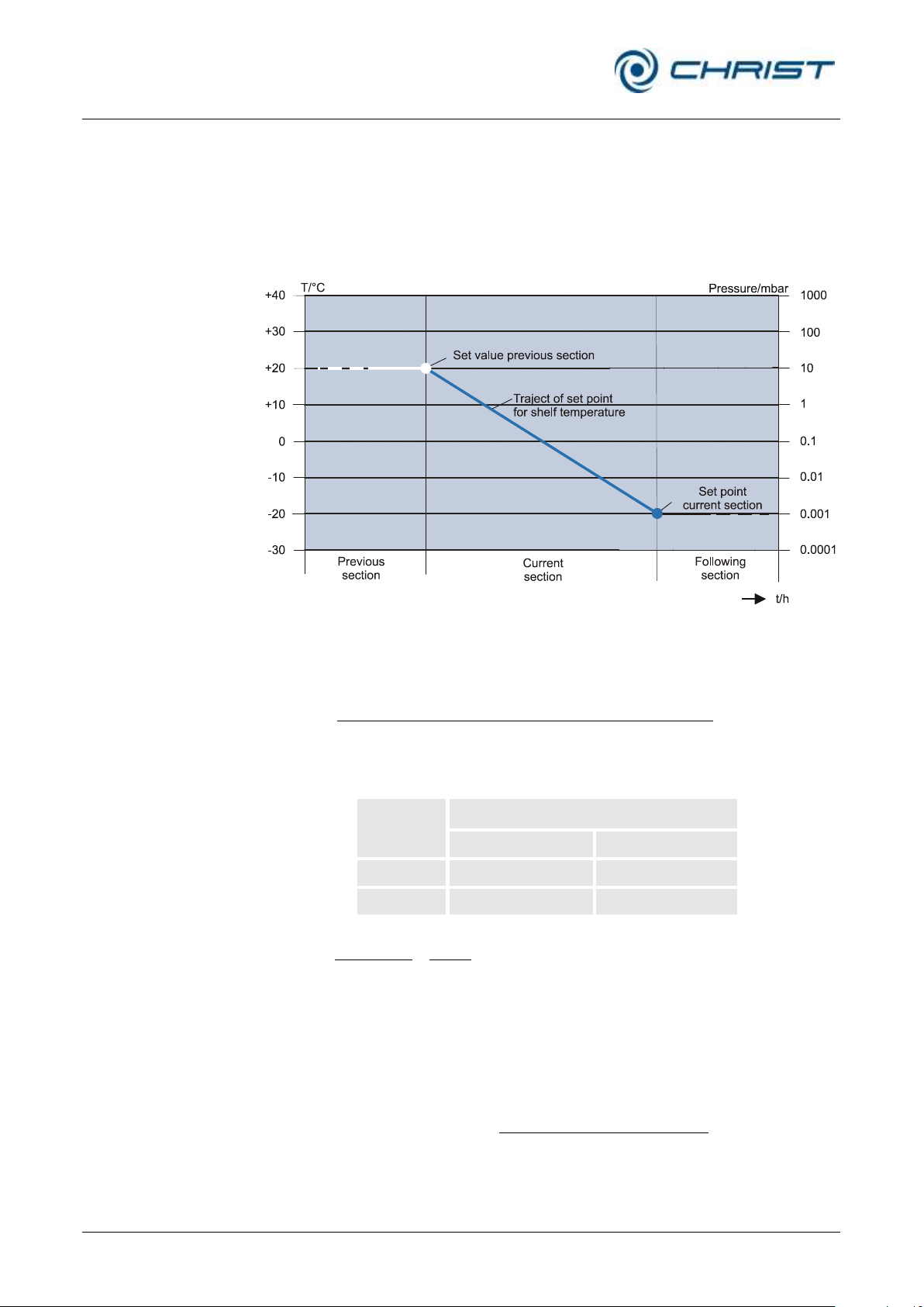
Rotational Vacuum Concentrator RVC 2-33 CDplus
with infrared heating
11 Appendix
72 / 88
Version 08/2009, Rev. 3.3 of 03/07/2016 • sb
Translation of the original operating manual
C/min][
secsec
secsec
tioncurrentoftimetion
tionpreviousofvaluesettioncurrentofvalueset
gradient
C][sec gradient time sectionelapsedtionpreviousofvaluesetvaluesetcontrol
Example:
Section
Set values
Section time [h:min]
Temperature [°C]
Preceding
...
30
Current
1:00
60
C/min 0.5
min60
30
min60
3060
CCC
gradient
C C/.CvaluesetControl
t
45min50min3030
min)30(
][ 10
sec
.)sec.(10.sec(10
.)sec.(10
mbarvaluesetcontrol
timetionelapsed
sectioncurrentoftimesection
tprevvaluesetLOGtcurrentvaluesetLOG
tprevvaluesetLOG
11 Appendix
11.1 Mathematical relations
The automatic processes in the “Programmer module” menu (see chapter
6.5.3.2 - "Program administration") are based on the following
considerations:
Fig. 62: Graphical representation of the course of the control setpoint
Calculation of the control set value and of the gradient for the
temperature:
After an elapsed section time of 30 minutes, for example, the control set
value for the temperature is:
Calculation of the control set value for the vacuum:
Page 73

Rotational Vacuum Concentrator RVC 2-33 CDplus
with infrared heating
11 Appendix
Version 08/2009, Rev. 3.3 of 03/07/2016 • sb
73 / 88
Translation of the original operating manual
11.2 Rotor program
The actual rotor program can be downloaded from
www.martinchrist.de/Products/RVC [unit type].
Page 74

Rotational Vacuum Concentrator RVC 2-33 CDplus
with infrared heating
11 Appendix
74 / 88
Version 08/2009, Rev. 3.3 of 03/07/2016 • sb
Translation of the original operating manual
Page 75

Rotational Vacuum Concentrator RVC 2-33 CDplus
with infrared heating
11 Appendix
Version 08/2009, Rev. 3.3 of 03/07/2016 • sb
75 / 88
Translation of the original operating manual
Vessel
Number
of
samples
Sample
volume
(ml)
Temperature
(°C)
Pump
Cooling
trap
Total
time
(min)
Water
10 ml test tube
24 9 45
MZ 2C
yes
635
10 ml test tube
24 9 60
MZ 2C
yes
510
1.5 ml Eppendorf caps
36 1 30
MZ 2C
yes
330
1.5 ml Eppendorf caps
36 1 45
MZ 2C
yes
270
1.5 ml Eppendorf caps
36 1 60
MZ 2C
yes
215
1.5 ml Eppendorf caps
36 1 30
KnF
no
330
1.5 ml Eppendorf caps
36 1 45
KnF
no
290
1.5 ml Eppendorf caps
36 1 60
KnF
no
230
Toluol
10 ml test tube
24 9 30
MZ 2C
yes
120
C6H5CH3
10 ml test tube
24 9 45
MZ 2C
yes
91
10 ml test tube
24 9 60
MZ 2C
yes
65
1.5 ml Eppendorf caps
36 1 30
MZ 2C
yes
40
1.5 ml Eppendorf caps
36 1 45
MZ 2C
yes
40
1.5 ml Eppendorf caps
36 1 60
MZ 2C
yes
30
Acetonitrile
10 ml test tube
24 9 30
MZ 2C
yes
120
C2H3N
10 ml test tube
24 9 45
MZ 2C
yes
100
10 ml test tube
24 9 60
MZ 2C
yes
80
1.5 ml Eppendorf caps
36 1 30
MZ 2C
yes
45
1.5 ml Eppendorf caps
36 1 45
MZ 2C
yes
40
1.5 ml Eppendorf caps
36 1 60
MZ 2C
yes
30
1,4 Dioxane
10 ml test tube
24 9 30
MZ 2C
yes
165
C4H8O2
10 ml test tube
24 9 45
MZ 2C
yes
110
10 ml test tube
24 9 60
MZ 2C
yes
80
1.5 ml Eppendorf caps
36 1 30
MZ 2C
yes
55
1.5 ml Eppendorf caps
36 1 45
MZ 2C
yes
45
1.5 ml Eppendorf caps
36 1 60
MZ 2C
yes
35
11.3 Overview of evaporation times
Page 76

Rotational Vacuum Concentrator RVC 2-33 CDplus
with infrared heating
11 Appendix
76 / 88
Version 08/2009, Rev. 3.3 of 03/07/2016 • sb
Translation of the original operating manual
Vessel
Number
of
samples
Sample
volume
(ml)
Temperature
(°C)
Pump
Cooling
trap
Total
time
(min)
Tert. butanol
10 ml test tube
24 9 30
MZ 2C
yes
150
C4 H10O
10 ml test tube
24 9 45
MZ 2C
yes
105
10 ml test tube
24 9 60
MZ 2C
yes
80
1.5 ml Eppendorf caps
36 1 30
MZ 2C
yes
55
1.5 ml Eppendorf caps
36 1 45
MZ 2C
yes
45
1.5 ml Eppendorf caps
36 1 60
MZ 2C
yes
35
Methanol
10 ml test tube
24 9 30
MZ 2C
yes
160
CH3OH
10 ml test tube
24 9 45
MZ 2C
yes
130
10 ml test tube
24 9 60
MZ 2C
yes
110
1.5 ml Eppendorf caps
36 1 30
MZ 2C
yes
65
1.5 ml Eppendorf caps
36 1 45
MZ 2C
yes
55
1.5 ml Eppendorf caps
36 1 60
MZ 2C
yes
45
Ethanol
10 ml test tube
24 9 30
MZ 2C
yes
165
C2H6O
10 ml test tube
24 9 45
MZ 2C
yes
120
10 ml test tube
24 9 60
MZ 2C
yes
105
1.5 ml Eppendorf caps
36 1 30
MZ 2C
yes
60
1.5 ml Eppendorf caps
36 1 45
MZ 2C
yes
50
1.5 ml Eppendorf caps
36 1 60
MZ 2C
yes
40
1,2 Dichlorethane
10 ml test tube
24 9 30
MZ 2C
yes
100
C2H4Cl2
10 ml test tube
24 9 45
MZ 2C
yes
75
10 ml test tube
24 9 60
MZ 2C
yes
60
1.5 ml Eppendorf caps
36 1 30
MZ 2C
yes
45
1.5 ml Eppendorf caps
36 1 45
MZ 2C
yes
35
1.5 ml Eppendorf caps
36 1 60
MZ 2C
yes
30
Page 77

Rotational Vacuum Concentrator RVC 2-33 CDplus
with infrared heating
11 Appendix
Version 08/2009, Rev. 3.3 of 03/07/2016 • sb
77 / 88
Translation of the original operating manual
11.4 Brief operating instructions
1. Switch on the system at the mains power switch down on the right side
of the unit.
2. Switch on the cooling trap and/or the vacuum pump.
3. Close the lid.
4. Starting the warm-up phase:
• Enter the set values for the warm-up phase into "menu" – "options" –
"Timer warm-up" und "Temperature warm-up", confirm your entries
and quit the menu.
• Press the left-hand function key "mode".
• Select the "Warm-up" menu and confirm.
• Open the lid when the warm up phase has ended.
• Install the rotors and close the lid.
5. Changing the set values for time, temperature, vacuum and safety
pressure:
• Select "menu" with the right-hand function key.
• Select "Change set values for manual mode" from the main menu.
• Select the set value by using the up/down keys and confirm with the
right-hand function key "edit".
• Change the set value by using the up/down keys and confirm with
the right-hand function key "ok".
• Quit the menu with the left-hand function key.
6. Starting the process "Evaporation manual" or "Evaporation program":
• Open the menu "Start with phase..." by pressing the left-hand
function key "mode".
• Select "Evaporation manual" or "Evaporation program" using the
up/down keys.
• Start the evaporation process by pressing the right-hand function
key.
• The function "Evaporation program" can only be selected if a
program has been created before.
• The start of the evaporation process starts the following automatic
process run:
- The rotor speed increases (rotating direction left),
- At 70% of the selected maximum speed: the aeration valve closes
automatically (to avoid delays in boiling),
- At 80% of the selected maximum speed: the stop valve opens the
connection to the vacuum pump,
- Further speed increase until the preselected maximum rotor speed
is reached.
7. Interrupting an evaporation process:
• Press the left-hand function key "mode".
• Select "Stop evaporation" and confirm.
Without an interruption, the evaporation process ends after the
preselected time. The following process runs automatically:
• At maximum speed: the stop valve closes the connection to the vacuum
pump, the aeration valve opens; the rotor speed is maintained for 30
sec (aeration phase, to avoid delays in boiling).
• Rotor decelerates until it is at a standstill. After the standstill of the rotor
the lid can be opened in order to remove the rotors.
Page 78
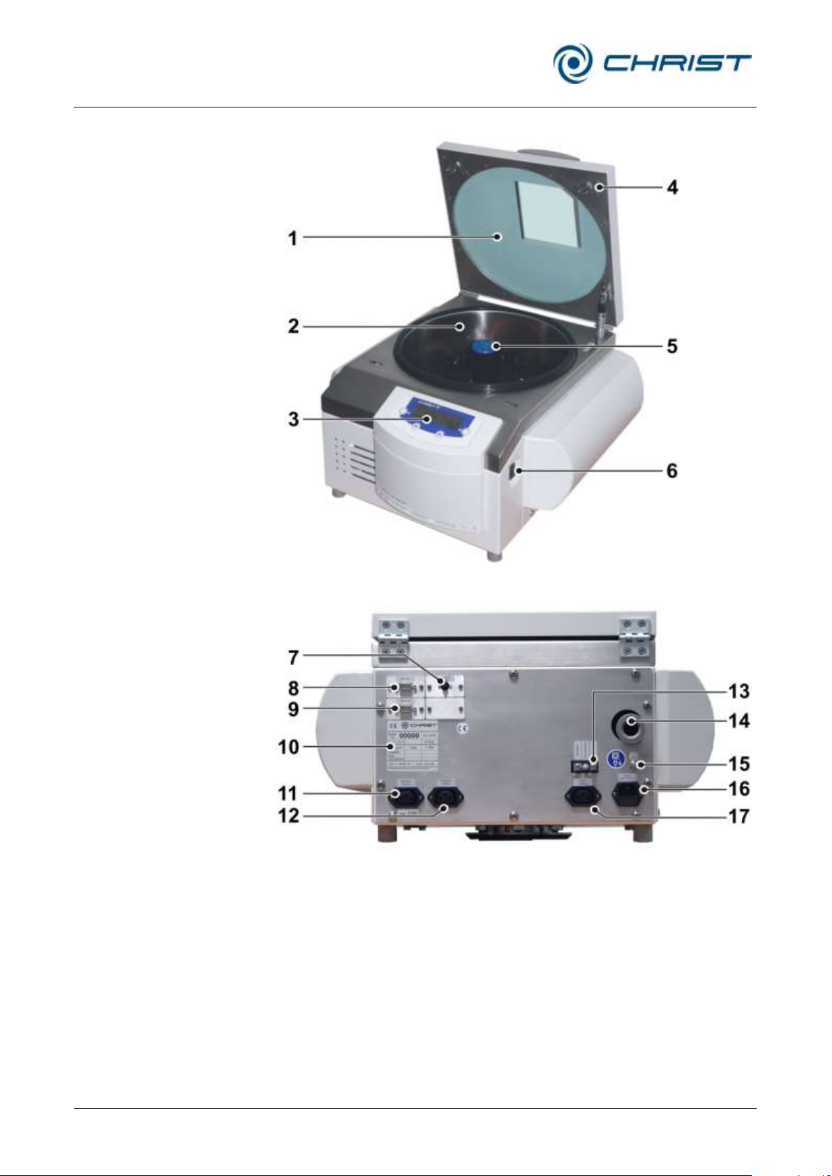
Rotational Vacuum Concentrator RVC 2-33 CDplus
with infrared heating
11 Appendix
78 / 88
Version 08/2009, Rev. 3.3 of 03/07/2016 • sb
Translation of the original operating manual
1 Lid
2 Rotor chamber
3 Control panel
4 Lid lock device
5 Rotor shaft
6 Mains power switch
7 Electrical vacuum measuring
sensor connection
8 Option: serial interface RS
232
9 Option: serial interface
Remote
10 Name plate
11 Power supply connection of
the vacuum pump
12 Power supply connection of
the pressure control valve
13 Valve block
14 Vacuum connection
15 Equipotential bonding screw
16 Mains connection and mains
fuse protection
17 Power supply connection of
the stop valve
Fig. 63: Total view of the RVC
Fig. 64: Rear view of the RVC
Function and control elements:
Page 79
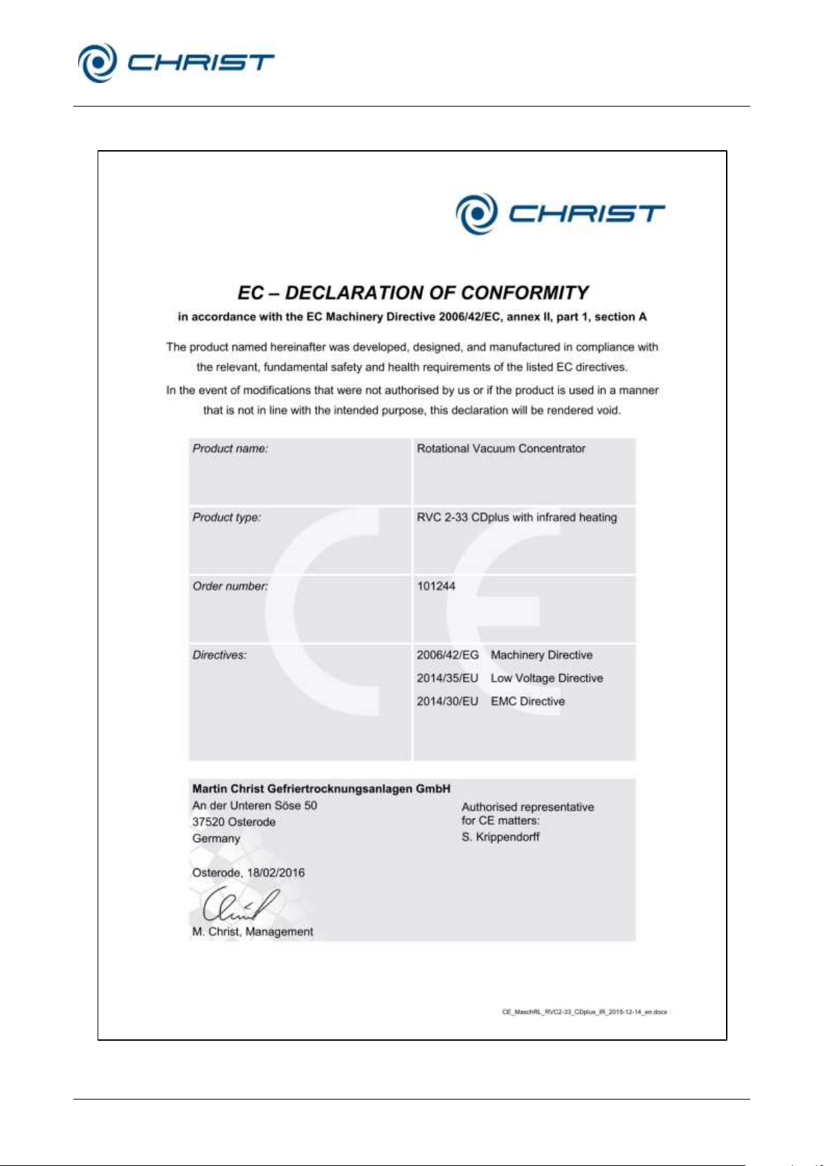
Rotational Vacuum Concentrator RVC 2-33 CDplus
with infrared heating
11 Appendix
Version 08/2009, Rev. 3.3 of 03/07/2016 • sb
79 / 88
Translation of the original operating manual
11.5 EC declaration of conformity
Page 80

Rotational Vacuum Concentrator RVC 2-33 CDplus
with infrared heating
11 Appendix
80 / 88
Version 08/2009, Rev. 3.3 of 03/07/2016 • sb
Translation of the original operating manual
Page 81
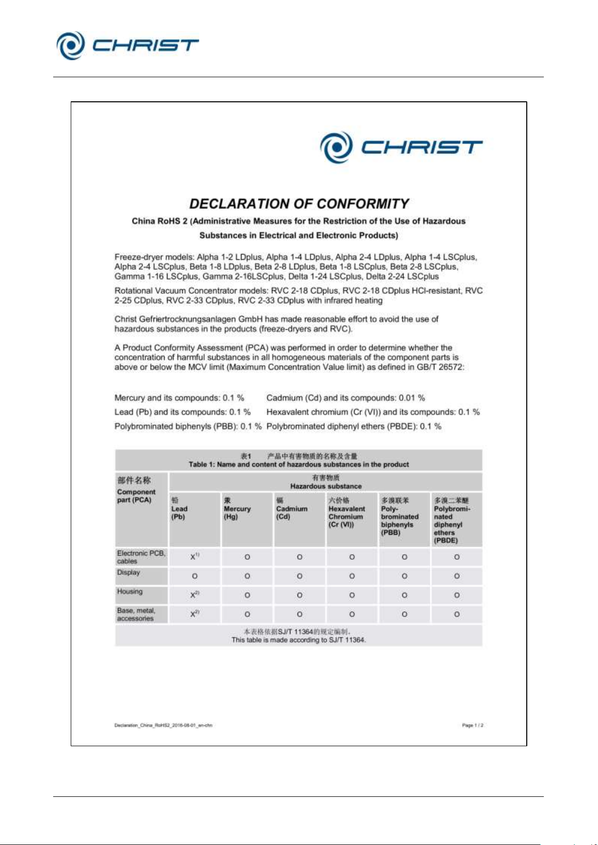
Rotational Vacuum Concentrator RVC 2-33 CDplus
with infrared heating
11 Appendix
Version 08/2009, Rev. 3.3 of 03/07/2016 • sb
81 / 88
Translation of the original operating manual
11.6 Declaration of conformity – China RoHS 2
Page 82
Rotational Vacuum Concentrator RVC 2-33 CDplus
with infrared heating
11 Appendix
82 / 88
Version 08/2009, Rev. 3.3 of 03/07/2016 • sb
Translation of the original operating manual
Page 83

Rotational Vacuum Concentrator RVC 2-33 CDplus
with infrared heating
12 Glossary
Version 08/2009, Rev. 3.3 of 03/07/2016 • sb
83 / 88
Translation of the original operating manual
12 Glossary
Boiling retardation
The temperature of a liquid can rise above the boiling point without the
liquid actually starting to boil. Vibrations or shocks quickly lead to the
formation of a large gas bubble that escapes explosively from the vessel.
This phenomenon is known as boiling retardation. It occurs when neither
the liquid nor the wall of the vessel include any condensation nuclei at
which vapour bubbles might form.
Pressure increase test
The pressure increase test is used to determine whether the evaporation in
the rotor chamber is complete. During the pressure increase test, the rotor
chamber is separated from the cooling trap or vacuum pump by way of the
stop valve. The system evaluates the pressure increase that is caused by
any additionally released steam.
In order to perform the pressure increase test, limits for the pressure
increase as well as the test duration must be defined beforehand.
Relative centrifugal force
The relative centrifugal force is the acceleration that the samples are
subjected to during the rotation. The acceleration is stated as a multiple of
the mean gravitational acceleration g. It can be increased by increasing the
radius inside the rotor chamber and by increasing the speed. These three
parameters are interdependent and linked with each other via the following
formula:
Relative centrifugal force RCF = 11.18 x 10⁻⁶ x r x n2
r = radius in cm
n = speed in rpm
RCF without any dimension
Page 84
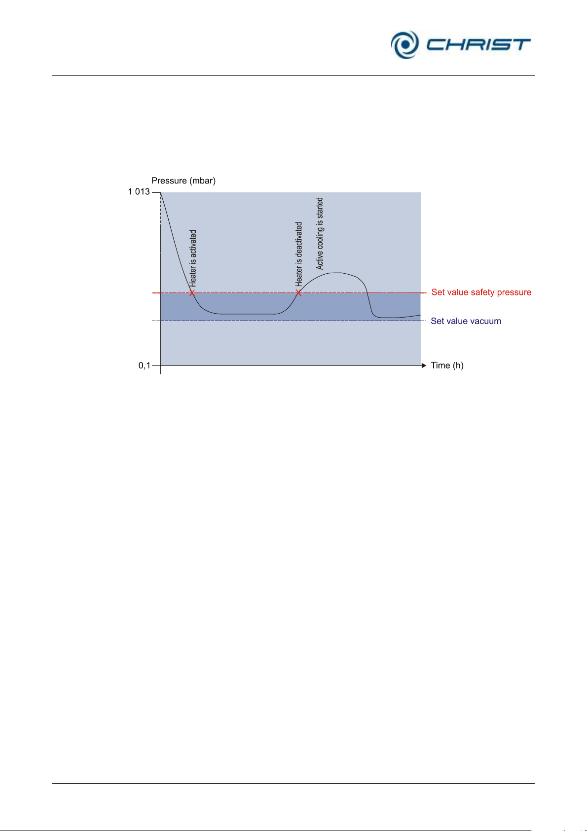
Rotational Vacuum Concentrator RVC 2-33 CDplus
with infrared heating
12 Glossary
84 / 88
Version 08/2009, Rev. 3.3 of 03/07/2016 • sb
Translation of the original operating manual
Safety pressure
Since the vacuum has a dominating influence on the product temperature,
Martin Christ Gefriertrocknungsanlagen GmbH has integrated a so-called
safety pressure function into their units in order to protect the products. If
the pressure inside the rotor chamber rises too quickly – above the safety
limit – the energy supply of the unit will be interrupted so that the
evaporation process slows down.
Fig. 65: Diagram describing the safety pressure function
Page 85

Rotational Vacuum Concentrator RVC 2-33 CDplus
with infrared heating
Index
Version 08/2009, Rev. 3.3 of 03/07/2016 • sb
85 / 88
Translation of the original operating manual
13 Index
A
Accessories ......................................... 10, 19
Accessories, cleaning and care .................. 64
Accident prevention ................................... 18
Active phases ............................................ 40
Advantages of the rotational vacuum
concentration .......................................... 14
Aeration and micro injection valve (Valve
block) ..................................................... 26
Aeration valve ............................................ 71
Aluminium accessories .............................. 66
Aluminium accessories, cleaning and care. 65
Aluminium rotor .......................................... 66
Ambient conditions ..................................... 71
Ambient temperature ................................. 71
Apparent power ................................... 12, 70
Assignment of the function keys ................. 39
Autoclaving ................................................ 66
B
Boiling retardation ...................................... 83
Brief operating instructions ......................... 77
Bucket ........................................................ 36
C
Calculation of the control set value and of the
gradient for the temperature ................... 72
Calculation of the control set value for the
vacuum .................................................. 72
Care of the accessories ............................. 64
CDplus configuration .................................. 52
CDplus control system ............................... 38
CE-Zeichen gemäß Richtlinie 2006/42/EG . 16
Chamber overtemperature ......................... 53
Change display contrast............................. 50
Changing the set values for the manual mode
............................................................... 43
Chemical and biological safety ................... 20
China RoHS 2 – Declaration of conformity . 81
Circuit diagrams ......................................... 71
Cleaning agents ......................................... 59
Cleaning of the rotor chamber .................... 60
Cleaning the rotational vacuum concentrator
............................................................... 59
Cleaning the RVC and the accessories ...... 59
Click at button push ................................... 51
Closing the lid ............................................ 32
Commissioning .......................................... 10
Condensation of the vapours upstream of the
vacuum pump in a cooling trap ............... 30
Connection................................................. 25
Connection for aeration and air injection with
ambient air (state of delivery) ................. 26
Connection for aeration and air injection with
inert gas ................................................. 27
Connection for aeration with ambient air and
air injectiowithinertgas ............................ 26
Connection of a vacuum pump and/or a
cooling trap ............................................. 29
Connection requirements ........................... 70
Continuous operation coldtrap ................... 51
Continuous operation vacuum pump .......... 51
Copying a program .................................... 47
Copyright ................................................... 10
Corrosion ................................. 35, 59, 60, 65
Cost estimate ............................................. 68
Cracks ....................................................... 65
Creating a new program ............................. 46
Customer-provided fuses ........................... 25
D
Dangerous goods....................................... 21
Dangerous materials .................................. 66
Declaration of conformity ........................... 79
Declaration of conformity – China RoHS 2 . 81
Declaration of decontamination .................. 68
Deleting a program .................................... 47
Dimensions ................................................ 23
Dimensions of the rotor chamber ............... 70
Dimensions of the unit ............................... 70
Direct hazard to the life and health ............. 17
Disinfection of the rotor chamber and
accessories ............................................ 66
Display ....................................................... 39
Disposal of the packaging .......................... 69
Disposal of the RVC ................................... 69
E
Earth conductor check ............................... 21
Page 86

Rotational Vacuum Concentrator RVC 2-33 CDplus
with infrared heating
Index
86 / 88
Version 08/2009, Rev. 3.3 of 03/07/2016 • sb
Translation of the original operating manual
EC-Declaration of conformity ..................... 79
Editing a program....................................... 46
Electrical connection .................................. 70
Electrical safety .......................................... 19
EMC according to EN 55011 ...................... 70
Emergency lid release ............................... 55
Emissions .................................................. 20
Equipment connection ............................... 71
Equipotential bonding screw ................ 21, 25
Error correction .......................................... 53
Error messages ................................... 21, 53
Evaporation with different tube sizes .......... 34
Evaporation with low capacity .................... 35
Examples of use ........................................ 15
Explanation of symbols .............................. 10
Explanation of the symbols and notes ........ 17
Extended service menu.............................. 52
F
Factory settings loaded .............................. 54
Fire prevention ........................................... 20
Form for the return of defective parts ......... 68
Function keys ............................................. 38
Functional and operating elements ............ 11
Fuses ......................................................... 20
G
General conditions ................................ ....... 9
General malfunctions ................................. 53
Glass breakage .......................................... 65
Glass tubes ................................................ 66
H
Hazard warnings .................................... 9, 32
High temperature resolution ....................... 51
Highly corrosive substances ...................... 19
I
Ice condenser temperature not reached ..... 54
Imbalance ............................................ 21, 33
Importance of the operating manual ............. 9
Important information ................................. 17
Infectious substances ................................ 20
Inflammable substances ............................ 20
Informal safety instructions ........................ 18
Information status ................................ ...... 49
Initial start-up ............................................. 32
Installation direction of the pressure control
valve ....................................................... 28
Installation of accessories .......................... 34
Installation of angle rotors .......................... 33
Installation of rotors and accessories ......... 33
Installation of swing-out rotors.................... 34
Installation site ........................................... 25
Intended use ................................................ 9
IO communication error.............................. 55
IP code ...................................................... 70
L
Layout of the RVC ...................................... 11
Lid cannot be opened ................................ 53
Lid contacts error ....................................... 53
Lid lock device ........................................... 21
Lid status ................................................... 40
Load default settings .................................. 52
M
Main menu ................................ ................. 43
Mains fuse ................................................. 70
Mains input ................................................ 71
Mains power failure .................................... 54
Mains power switch .................................... 32
Maintenance .............................................. 59
Maintenance and service ........................... 59
Malfunctions ............................................... 53
Manual evaporation ................................... 42
Manufacturer .......................20, 21, 59, 69, 70
Marking of the unit ..................................... 16
Mathematical relations ............................... 72
Max. density of material at process start .... 70
Max. humidity ............................................. 71
Max. lid opening angle ............................... 70
Max. permissible imbalance ....................... 70
Maximum current for the vacuum pump ..... 29
Mechanical safety ...................................... 19
Micro injection valve ................................... 71
Mode .......................................................... 41
Mode of operation ...................................... 13
N
Name plate .................................... 12, 19, 25
No ice condenser sensor signal ................. 53
No rotor chamber sensor signal ................. 53
No rotor detected (only Triple TMM)........... 54
Page 87

Rotational Vacuum Concentrator RVC 2-33 CDplus
with infrared heating
Index
Version 08/2009, Rev. 3.3 of 03/07/2016 • sb
87 / 88
Translation of the original operating manual
No rotor sensor signal ................................ 53
No vacuum sensor signal ........................... 53
Noise level according to DIN 45635 ........... 70
Nominal current ......................................... 70
Nominal rotor speed not reached ............... 54
Nominal voltage ................................... 12, 19
Notes on safety and hazards ....................... 9
O
On-site transport ........................................ 24
Opening the lid ..................................... 32, 41
Operating elements .................................... 11
Operating mode ......................................... 40
Operating personnel .................................. 18
Operating voltage....................................... 25
Option: Pressure control valve and vacuum
sensor .................................................... 28
Option: Remote control of the cooling trap via
RVC ....................................................... 31
Options ...................................................... 50
Order number ............................................ 70
Overview of evaporation times ................... 75
P
Packaging .................................................. 23
Packaging, disposal ................................... 69
Part number ............................................... 12
Pathogenic substances .............................. 20
Pending information ................................... 40
Performance data ................................ ...... 70
Permissible imbalance exceeded ............... 54
Physical data ............................................. 70
Pivotal point ......................................... 36, 37
Polycarbonate tubes .................................. 66
Polypropylene tubes .................................. 66
Potential hazard to the life and health ........ 17
Potentially hazardous situation................... 17
Power cord................................................. 19
Power failure safety ................................... 21
Power supply ............................................. 25
Pressure control valve ......................... 28, 71
Pressure control valve connection ............. 70
Pressure increase test ......................... 48, 83
Pressure marks .......................................... 65
Prevention of accidents .......................... 9, 18
Principle of the rotational vacuum
concentration .......................................... 13
Procedures in the event of hazards and
accidents ................................................ 22
Process and equipment information ........... 49
Process messages ..................................... 54
Program administration .............................. 45
Program memory informationen ................. 47
Program-controlled evaporation ................. 42
Protection class ......................................... 70
Protection of the environment .................... 18
R
Radioactive substances ............................. 20
Rated current ............................................. 12
Relative centrifugal force ............................ 70
Remaining hazards .................................... 22
Remote control of the cooling trap via RVC 31
Remove the glass particles and the metal
dust from the rotor chamber ................... 66
Responsibility of the operator ..................... 18
Return of defective parts ............................ 67
Risk of burns .............................................. 41
Rotor blocks ............................................... 36
Rotor chamber, cleaning ............................ 60
Rotor overtemperature ............................... 53
Rotor speed ............................................... 51
S
Safety area ................................................ 21
Safety class ......................................... 19, 25
Safety data sheets ..................................... 71
Safety devices ........................................... 21
Safety distance .............................. 19, 21, 25
Safety instructions .................................. 9, 32
Safety instructions for evaporation ............. 21
Safety pressure .................................... 44, 84
Safety pressure not reached ...................... 54
Safety-conscious work ............................... 18
Scope of supply ......................................... 10
Select language ......................................... 50
Serial interface ........................................... 71
Serial number ................................ 12, 58, 67
Service ....................................................... 67
Service contact .......................................... 58
Service life ........................................... 59, 65
Service life of the accessories .................... 66
Service menu ............................................. 51
Settings ...................................................... 50
Page 88

Rotational Vacuum Concentrator RVC 2-33 CDplus
with infrared heating
Index
88 / 88
Version 08/2009, Rev. 3.3 of 03/07/2016 • sb
Translation of the original operating manual
Set-up and connection ............................... 25
Signs of corrosion ...................................... 65
Small flange connections ........................... 57
Solvents. .................................................... 59
Special functions ........................................ 48
Specialist personnel ................................... 67
Speed ........................................................ 70
Standards and regulations ......................... 10
Status bar ................................ .................. 40
Stop valve .................................................. 71
Stop valve connection ................................ 70
Stopping the evaporation process
prematurely ............................................ 42
Stopping the warm-up phase prematurely .. 42
Storage and transport ................................ 23
Storage conditions ..................................... 23
Stress-corrosion ......................................... 64
Supply voltage ........................................... 25
Surface temperature ............................ 20, 41
Susceptibility to corrosion .......................... 65
Switching the RVC on ................................ 32
System check ............................................ 21
System messages ...................................... 55
T
Technical data ........................................... 70
Technical documentation ........................... 71
Teflon tubes ............................................... 66
Temperature ........................................ 44, 70
Temperature Warm-up ............................... 51
Thermal safety ........................................... 20
Thermal stress ..................................... 25, 59
Timer Evaporation ...................................... 44
Timer Heating ............................................ 44
Timer Warm-up .......................................... 51
Toxic substances ....................................... 20
Transport safety devices ............................ 24
Tubes ......................................................... 35
Type..................................................... 12, 70
Type of the RVC ........................................ 67
U
Up and down keys ..................................... 38
User interface ............................................ 38
UV radiation ......................................... 25, 59
V
Vacuum ..................................................... 44
Vacuum connection ............................. 27, 71
Vacuum pump ............................................ 71
Vacuum pump connection .......................... 70
Vacuum sensor .................................... 28, 71
Values window ........................................... 39
Valve block ................................................ 26
Vapour pressure curve for ice and water .... 13
Ventilation .................................................. 25
Visible damage of the surface .................... 65
VSK3000 calibration error .......................... 54
W
Warm-up .................................................... 41
Warranty and liability .................................... 9
Weight ................................................. 23, 70
Withdrawal of the vapours by a vacuum
pump ...................................................... 29
Y
Year of manufacture .................................. 12
 Loading...