

Page 1
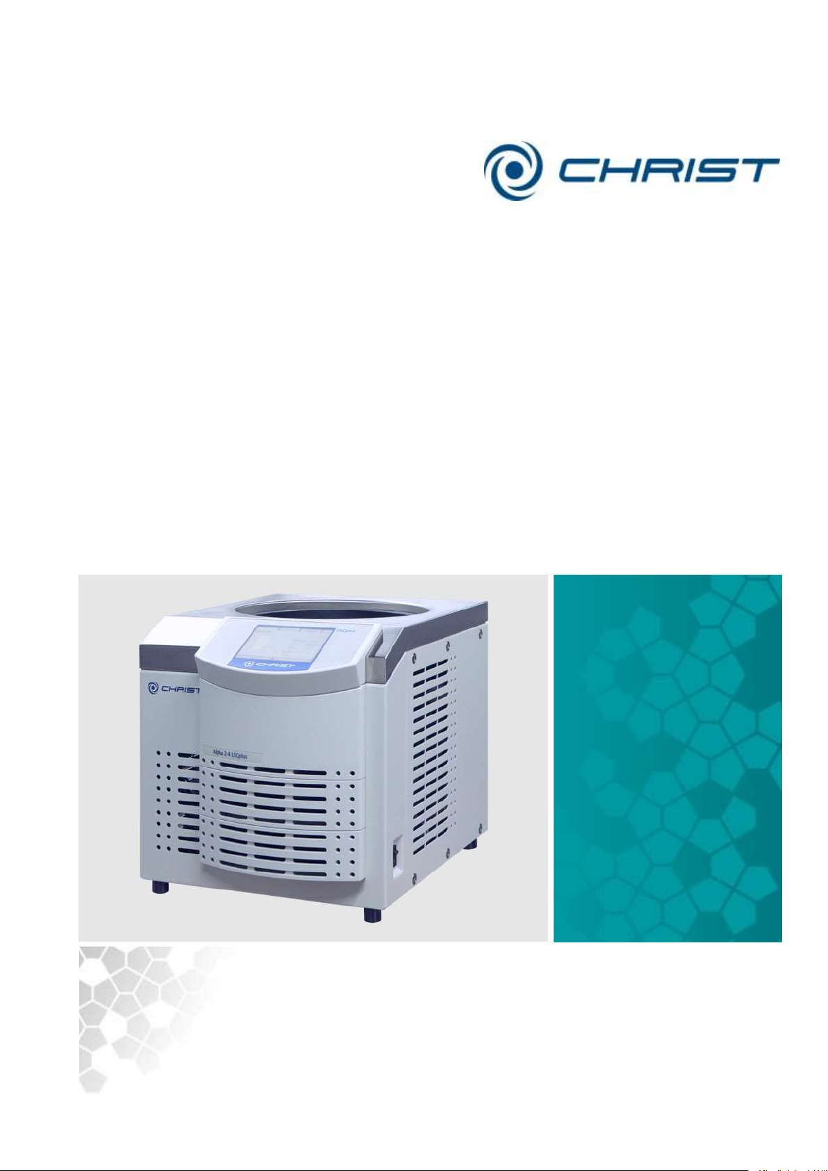
Translation of the original operating manual
sb
Freeze-dryer
Rev. 2.3 of 03/07/2017
Alpha 1-4 LSCplus;Freeze-dryer;Alpha 2-4 LSCplus
Version 01/2011
Alpha 1-4 LSCplus
Part no. 102141
Alpha 2-4 LSCplus
Part no. 102142
Freeze-dryer
Operating Manual
Please retain for later use!
Page 2

Freeze-dryer Alpha 1-4 LSCplus
Freeze-dryer Alpha 2-4 LSCplus
2 / 131
Version 01/2011, Rev. 2.3 of 03/07/2017 • sb
Translation of the original operating manual
Page 3

Freeze-dryer Alpha 1-4 LSCplus
Freeze-dryer Alpha 2-4 LSCplus
Version 01/2011, Rev. 2.3 of 03/07/2017 • sb
3 / 131
Translation of the original operating manual
In case of inquiries, please state the following numbers:
Order number:
Serial number:
© Copyright by
Martin Christ Gefriertrocknungsanlagen GmbH
An der Unteren Söse 50
37520 Osterode am Harz
Germany
Tel.: +49 (0) 5522 / 5007-0
Fax: +49 (0) 5522 / 5007-12
Web: www.martinchrist.de
E-mail: [email protected]
Page 4

Freeze-dryer Alpha 1-4 LSCplus
Freeze-dryer Alpha 2-4 LSCplus
4 / 131
Version 01/2011, Rev. 2.3 of 03/07/2017 • sb
Translation of the original operating manual
Page 5

Freeze-dryer Alpha 1-4 LSCplus
Freeze-dryer Alpha 2-4 LSCplus
Table of contents
Version 01/2011, Rev. 2.3 of 03/07/2017 • sb
5 / 131
Translation of the original operating manual
1 General information ............................................................................................................. 9
1.1 Importance of the operating manual .................................................................................. 9
1.2 Intended use ..................................................................................................................... 9
1.3 Warranty and liability......................................................................................................... 9
1.4 Copyright ........................................................................................................................ 10
1.5 Explanation of symbols ................................................................ ................................... 10
1.6 Standards and regulations .............................................................................................. 10
1.7 Scope of supply .............................................................................................................. 10
2 Layout and mode of operation .......................................................................................... 11
2.1 Layout of the freeze-dryer ............................................................................................... 11
2.1.1 Functional and operating elements ............................................................................ 11
2.1.2 Name plate ................................................................................................................ 13
2.2 Mode of operation ........................................................................................................... 14
2.2.1 General information on freeze-drying ................................................................ ......... 14
2.2.2 Freeze-drying process ............................................................................................... 17
2.2.2.1 Preparation ........................................................................................................ 17
2.2.2.2 Freezing ............................................................................................................. 17
2.2.2.3 Main drying ........................................................................................................ 18
2.2.2.4 Final drying ........................................................................................................ 19
2.2.2.5 End of drying and aeration ................................................................................. 19
2.2.2.6 Defrosting .......................................................................................................... 19
3 Safety .................................................................................................................................. 20
3.1 Marking of the unit .......................................................................................................... 20
3.2 Explanation of the symbols and notes ............................................................................. 21
3.3 Responsibility of the operator .......................................................................................... 22
3.4 Operating personnel ....................................................................................................... 22
3.5 Informal safety instructions ............................................................................................. 23
3.6 Safety instructions .......................................................................................................... 23
3.6.1 Electrical safety ......................................................................................................... 24
3.6.2 Mechanical safety ...................................................................................................... 24
3.6.3 Fire prevention ................................ ................................................................ ........... 25
3.6.4 Thermal safety ........................................................................................................... 25
3.6.5 Chemical and biological safety .................................................................................. 25
3.7 Safety devices ................................ ................................................................................ 26
3.7.1 System check ............................................................................................................ 26
3.7.2 Earth conductor check ............................................................................................... 26
3.8 Procedures in the event of hazards and accidents .......................................................... 26
3.9 Remaining hazards ......................................................................................................... 27
Page 6

Freeze-dryer Alpha 1-4 LSCplus
Freeze-dryer Alpha 2-4 LSCplus
Table of contents
6 / 131
Version 01/2011, Rev. 2.3 of 03/07/2017 • sb
Translation of the original operating manual
4 Storage and transport ....................................................................................................... 28
4.1 Dimensions and weight ................................................................................................... 28
4.2 Storage conditions .......................................................................................................... 28
4.3 Notes on transport .......................................................................................................... 29
4.4 Packaging ....................................................................................................................... 30
4.5 Transport safety device ................................................................................................... 30
5 Set-up and connection ...................................................................................................... 31
5.1 Installation site ................................................................................................................ 31
5.2 Power supply .................................................................................................................. 32
5.2.1 Connection ................................................................................................................ 32
5.2.2 Customer-provided fuses ........................................................................................... 32
5.3 Aeration valve ................................................................................................................. 32
5.4 Media drain valve ............................................................................................................ 32
5.5 Vacuum sensor ............................................................................................................... 33
5.6 Vacuum pump................................................................................................................. 35
5.7 Pressure control valve .................................................................................................... 36
5.8 Rubber valves ................................................................................................................. 37
6 Operation ............................................................................................................................ 38
6.1 Initial start-up .................................................................................................................. 38
6.2 Installation of accessories ............................................................................................... 38
6.3 Preparation ..................................................................................................................... 38
6.4 Switching the freeze-dryer on ......................................................................................... 38
6.5 LSCplus control system .................................................................................................. 39
6.5.1 User interface ............................................................................................................ 39
6.5.1.1 Main window "Manual" ....................................................................................... 40
6.5.1.2 Main window "Program" ..................................................................................... 49
6.5.1.3 Main window "Options " ..................................................................................... 50
6.5.1.4 Main window "?" ................................................................................................. 62
6.5.2 Manual freeze-drying ................................................................................................. 62
6.5.2.1 Entering set values in the manual mode............................................................. 63
6.5.3 Option: freeze-drying with the PGMplus programmer module .................................... 65
6.5.3.1 Creating a program ............................................................................................ 69
6.5.3.2 Editing a program ............................................................................................... 74
6.5.3.3 Copying a program ............................................................................................ 75
6.5.3.4 Loading a program ............................................................................................. 75
6.5.3.5 Deleting a program ............................................................................................ 76
6.6 Optional extensions ........................................................................................................ 77
6.7 Switching the freeze-dryer OFF ...................................................................................... 78
Page 7

Freeze-dryer Alpha 1-4 LSCplus
Freeze-dryer Alpha 2-4 LSCplus
Table of contents
Version 01/2011, Rev. 2.3 of 03/07/2017 • sb
7 / 131
Translation of the original operating manual
7 Malfunctions and error correction .................................................................................... 79
7.1 General malfunctions ...................................................................................................... 79
7.1.1 Power failure .............................................................................................................. 80
7.1.2 Insufficient vacuum .................................................................................................... 81
7.1.2.1 Small flange connections ................................................................................... 81
7.1.2.2 Aeration valve, media drain valve ...................................................................... 82
7.1.2.3 Pressure control valve ........................................................................................ 82
7.1.2.4 Rubber valves .................................................................................................... 82
7.1.2.5 Vacuum sensor ................................................................................................ .. 82
7.1.3 Insufficient ice condenser temperature ................................................................ ...... 83
7.2 Process and error messages .......................................................................................... 83
7.3 Service contact ............................................................................................................... 84
8 Maintenance and service ................................................................................................... 85
8.1 Maintenance ................................................................................................................... 85
8.1.1 General ...................................................................................................................... 85
8.1.2 Ice condenser chamber ................................................................ ............................. 86
8.1.3 Aeration valve, media drain valve .............................................................................. 86
8.1.4 Heat exchanger (only for air-cooled freeze-dryers) .................................................... 87
8.1.5 Vacuum pump ........................................................................................................... 87
8.1.6 Exhaust filter (oil mist separator) ................................................................................ 88
8.1.7 Vacuum sensor .......................................................................................................... 88
8.1.8 Accessories ............................................................................................................... 88
8.2 Disinfection of the drying chamber and accessories ....................................................... 89
8.3 Service ........................................................................................................................... 90
8.4 Return of defective parts ................................................................................................. 90
9 Disposal .............................................................................................................................. 92
9.1 Disposal of the freeze-dryer ............................................................................................ 92
9.2 Disposal of the packaging ............................................................................................... 92
10 Technical data .................................................................................................................... 93
10.1 Ambient conditions ......................................................................................................... 95
10.2 Technical documentation ................................................................................................ 95
11 Appendix ............................................................................................................................ 96
11.1 Mathematical relations ................................................................................................ .... 96
11.2 Brief operating instructions ............................................................................................. 97
11.3 EC declaration of conformity in accordance with the EC Machinery Directive ............... 103
11.4 Declaration of conformity – China RoHS 2 .................................................................... 105
11.5 Resistance to stress cracking and chemical influences "Plexiglas" ............................... 107
12 Glossary ........................................................................................................................... 125
13 Index ................................................................................................................................. 127
Page 8

Freeze-dryer Alpha 1-4 LSCplus
Freeze-dryer Alpha 2-4 LSCplus
Table of contents
8 / 131
Version 01/2011, Rev. 2.3 of 03/07/2017 • sb
Translation of the original operating manual
Page 9

Freeze-dryer Alpha 1-4 LSCplus
Freeze-dryer Alpha 2-4 LSCplus
1 General information
Version 01/2011, Rev. 2.3 of 03/07/2017 • sb
9 / 131
Translation of the original operating manual
1 General information
1.1 Importance of the operating manual
A fundamental requirement for the safe and trouble-free operation of the
unit is to be familiar with the fundamental safety instructions and all
possible hazards.
The operating manual includes important information concerning the safe
operation of the freeze-dryer.
This operating manual, and in particular the notes on safety and hazards,
must be observed by all persons operating the unit.
In addition, the local rules and regulations for the prevention of accidents
must be complied with.
1.2 Intended use
CHRIST freeze-dryers have been solely designed for the freeze-drying of
solid or liquid products in ampoules, vials or dishes. They are, therefore,
solely intended for these applications.
The freeze-dryer is suitable
• for freeze-drying materials such as bacteria and virus cultures, blood
plasma, serum fractions, antibodies, sera, vaccines, and
pharmaceutical products
• for freeze-drying plant extracts, e.g. for biochemical tests
• for freeze-drying inorganic materials, e.g. nanoparticles
• for freeze-drying numerous other products (for further information
please contact our qualified personnel)
Any other use beyond this area of application is regarded as improper use.
Martin Christ Gefriertrocknungsanlagen GmbH cannot be held liable for any
damage resulting from such improper use.
The intended use also includes:
• observation of all the notes and instructions included in the operating
manual
• compliance with the inspection and maintenance instruction
• prohibition of any type of extensions to, or conversions of the unit.
1.3 Warranty and liability
The warranty and liability are subject to our "General Terms and
Conditions" that were distributed to the operator upon the conclusion of the
contract.
Warranty and liability claims are excluded if they are due to one or several
of the following reasons:
• improper use
• non-compliance with the safety instructions and hazard warnings in the
• improper installation, start-up, operation, and maintenance of the
operating manual
freeze-dryer.
Page 10

Freeze-dryer Alpha 1-4 LSCplus
Freeze-dryer Alpha 2-4 LSCplus
1 General information
10 / 131
Version 01/2011, Rev. 2.3 of 03/07/2017 • sb
Translation of the original operating manual
1.4 Copyright
The copyright concerning the operating manual remains with Martin Christ
Gefriertrocknungsanlagen GmbH.
The operating manual is solely intended for the operator and their
personnel. It includes instructions and information that may not be
• duplicated,
• distributed, or
• communicated in any other way neither in full nor in parts.
Non-compliance may be prosecuted under criminal law.
1.5 Explanation of symbols
In this operating manual, specialist terms that are explained in the glossary
(see chapter 12 - "Glossary") are marked by an arrow and printed in italics
(e.g. sublimation).
1.6 Standards and regulations
EC declaration of conformity in accordance with the EC Machinery
Directive (see chapter 11.3 - "EC declaration of conformity in accordance
with the EC Machinery Directive")
1.7 Scope of supply
The scope of supply comprises:
• 1 tube of high-vacuum grease
• 1 litre of vacuum pump oil (only if a pump is included)
• 1 set of flange components and several small parts for service and
maintenance purposes
• 1 drain hose 0.5 m (silicone 8 x 12 mm)
• 1 operating manual
Accessories and commissioning
According to your order, our order confirmation, and our delivery note.
Page 11
Freeze-dryer Alpha 1-4 LSCplus
Freeze-dryer Alpha 2-4 LSCplus
2 Layout and mode of operation
Version 01/2011, Rev. 2.3 of 03/07/2017 • sb
11 / 131
Translation of the original operating manual
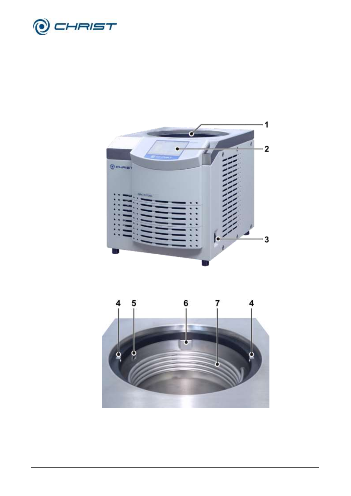
1 Ice condenser
chamber with an
internal ice condenser
2 User interface (see
chapter 6.5.1 - "User
interface")
3 Mains power switch
4 Contact piece
5 Vacuum sensor
6 Pipe connection of the
vacuum pump (behind
the cover plate)
7 Ice condenser
2 Layout and mode of operation
2.1 Layout of the freeze-dryer
2.1.1 Functional and operating elements
Fig. 1: Total view of the freeze-dryer
Fig. 2: Ice condenser chamber
Page 12
Freeze-dryer Alpha 1-4 LSCplus
Freeze-dryer Alpha 2-4 LSCplus
2 Layout and mode of operation
12 / 131
Version 01/2011, Rev. 2.3 of 03/07/2017 • sb
Translation of the original operating manual
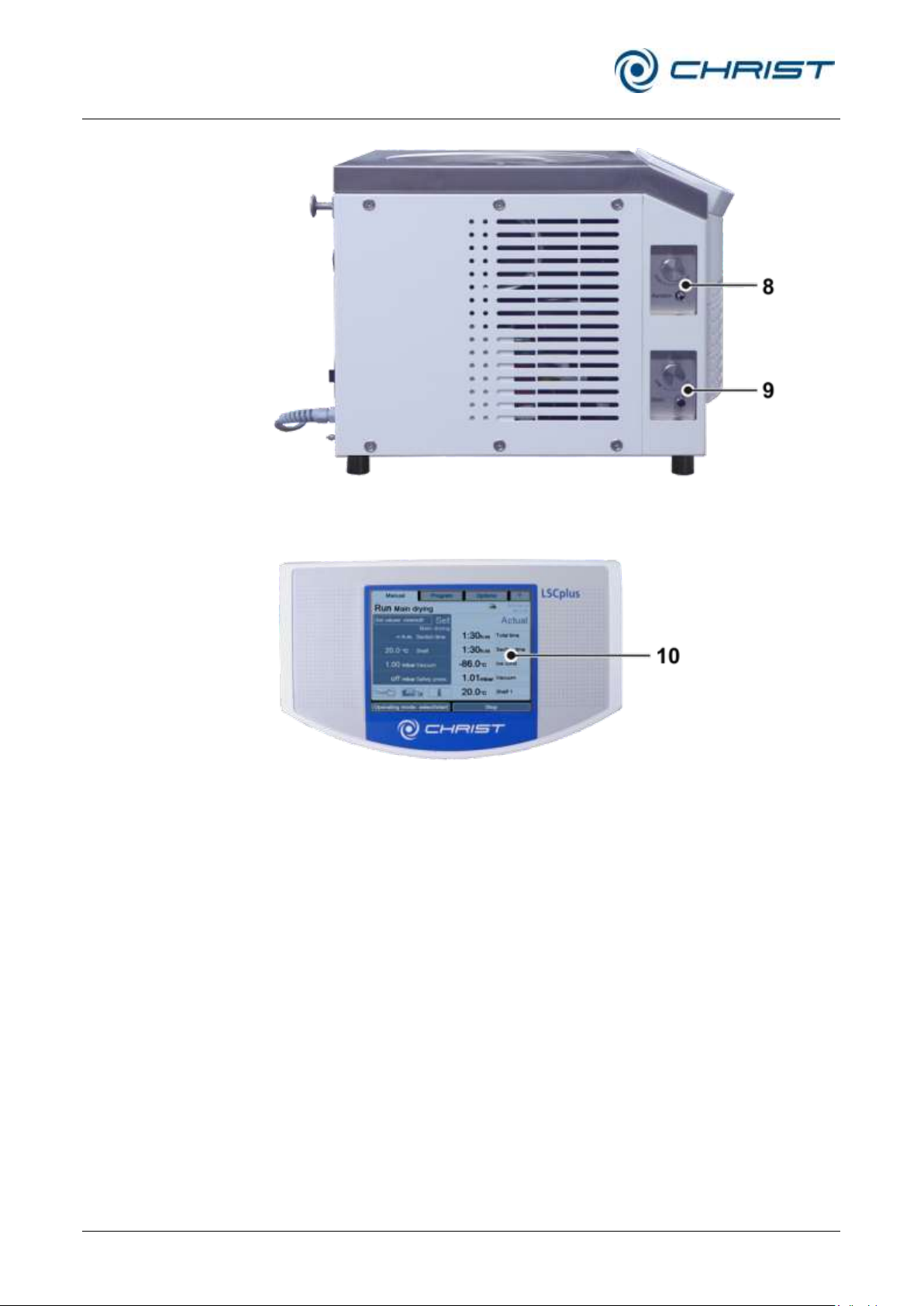
8 Aeration valve
9 Media drain valve
10 Touchpanel
Fig. 3: Left side of the freeze-dryer
Fig. 4: User interface with touchpanel
Page 13
Freeze-dryer Alpha 1-4 LSCplus
Freeze-dryer Alpha 2-4 LSCplus
2 Layout and mode of operation
Version 01/2011, Rev. 2.3 of 03/07/2017 • sb
13 / 131
Translation of the original operating manual
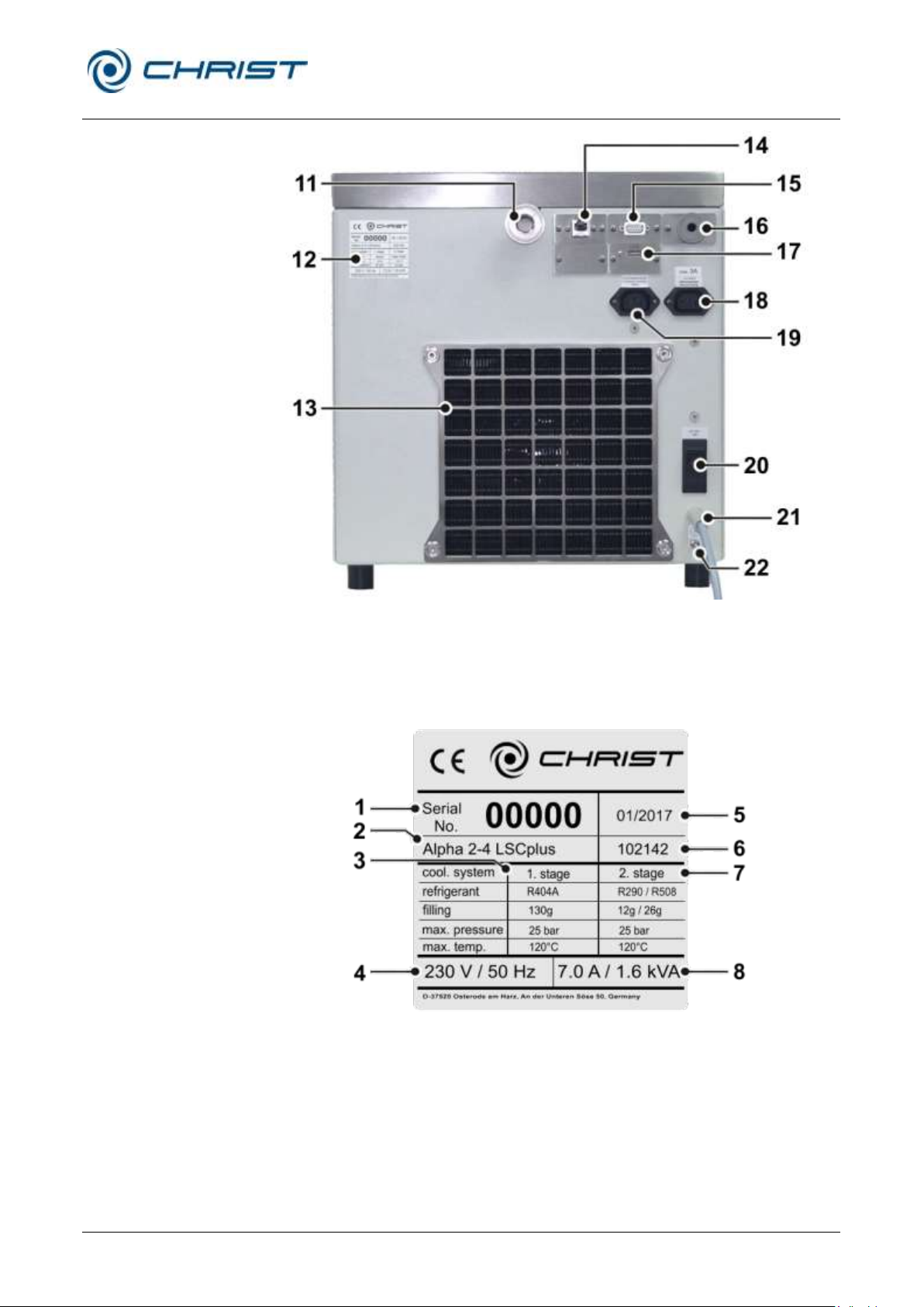
11 Vacuum connection
12 Name plate (see
chapter 2.1.2 - "Name
plate")
13 Heat exchanger of the
refrigeration unit
14 Data interface
15 Electrical connection of
the vacuum sensor
16 Connection of the
vacuum sensor
17 Option: USB port
18 Power supply of the
vacuum pump
19 Power supply of the
pressure control valve
20 Mains fuse
21 Mains cable
22 Equipotential bonding
screw
1 Serial number
2 Type
3 Refrigerant data of
the 1st stage
4 Nominal voltage
5 Year of manufacture
(month/year)
6 Part number
7 Refrigerant data of
the 2nd stage
8 Rated current /
apparent power
Fig. 6: Example of a name plate (here: Alpha 2-4 LSCplus)
2.1.2 Name plate
Fig. 5: Rear view of the freeze-dryer
Page 14

Freeze-dryer Alpha 1-4 LSCplus
Freeze-dryer Alpha 2-4 LSCplus
2 Layout and mode of operation
14 / 131
Version 01/2011, Rev. 2.3 of 03/07/2017 • sb
Translation of the original operating manual
2.2 Mode of operation
2.2.1 General information on freeze-drying
What is freeze-drying?
Freeze-drying or lyophilisation is a procedure for the gentle drying of highquality products. The product is dried by sublimation without passing
through the liquid phase.
What are typical applications for freeze-drying?
As far as their sheer quantity is concerned, foodstuffs are the major
application for freeze-drying. One widely known example is the production
of granulated instant coffee or the drying of fruit, e.g. for breakfast cereals.
Other areas of application are the restoration of water-damaged documents
or the drying of archaeological artefacts.
Another important area of application is the drying of biotechnological and
pharmaceutical products, e.g. tissues and tissue extracts, bacteria,
vaccines, and sera. Products that would not keep well when they are
dissolved in water can be preserved by freeze-drying. During this process,
the biological properties of these sensitive substances are preserved. The
compounds remain unchanged from a qualitative and quantitative point of
view. After the addition of water, the products will have the same
characteristics as the original products.
How does freeze-drying work?
Freeze-drying is a very gentle procedure for the extraction of water from a
product in the frozen state. The drying process takes place through
sublimation, i.e. the direct transition of a product from the solid phase to the
gas phase. This happens under vacuum.
The following section describes the process of sublimation based on the
example of water, since most products that are processed by freeze-drying
are aqueous solutions. Their behaviour is based on identical fundamental
principles.
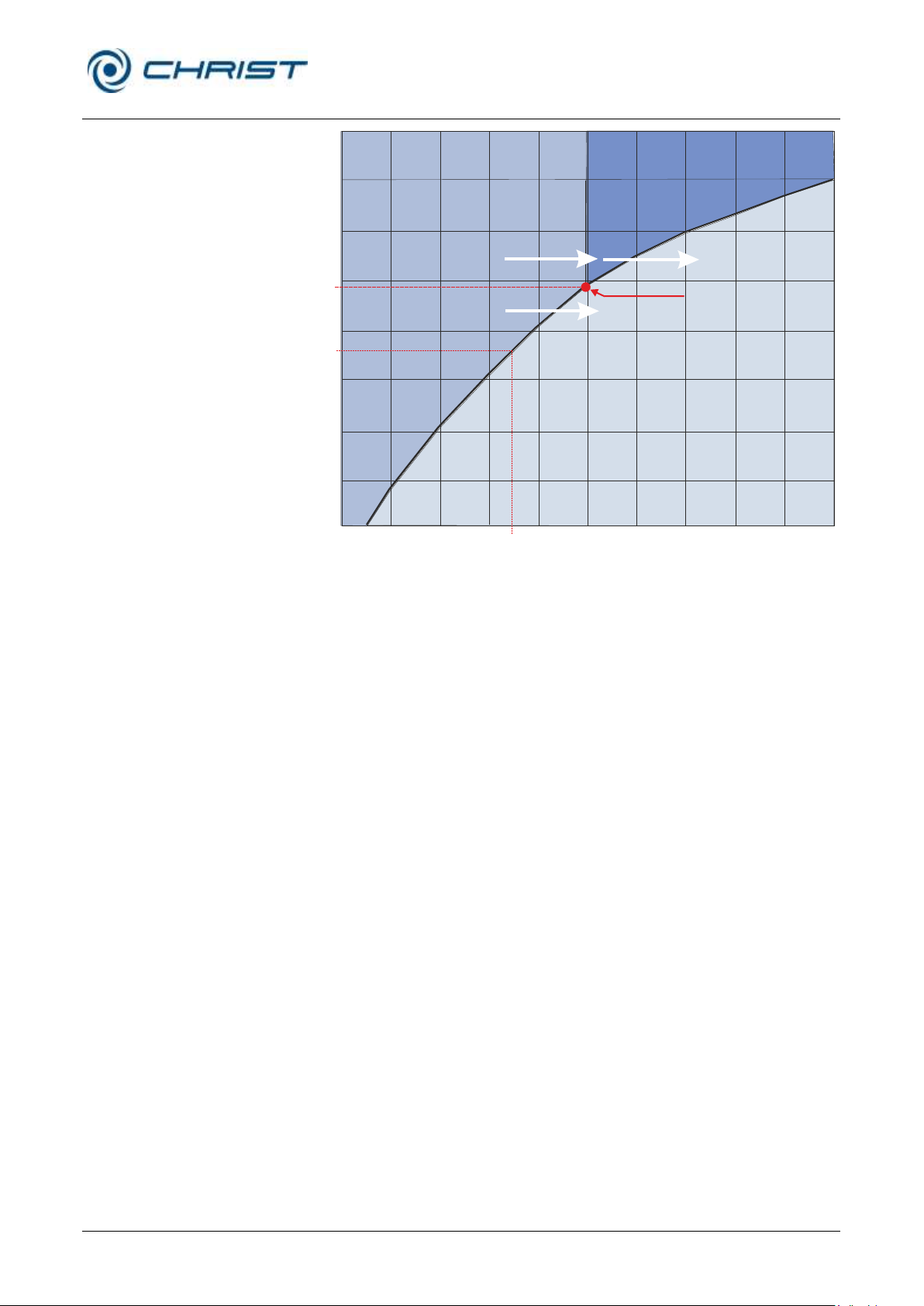
The vapour pressure curve above ice describes the phase transition as a
function of the pressure and temperature. The higher the temperature is,
the higher the vapour pressure.
• If the vapour pressure is higher than 6.11 mbar (A), water passes
through all three phases: solid, liquid, and gas (see the illustration).
• If the vapour pressure is below 6.11 mbar (B) and energy is added, the
ice will be directly converted into water vapour once the sublimation
curve is reached. This transition is called “sublimation”. If thermal
energy is added to pure ice with a temperature of less than –30°C at a
pressure of 0.37 mbar, it will be converted into water vapour once it
reaches –30°C (see figure).
The vacuum prevents the melting of ice when energy is added. If thermal
energy is added to a frozen product under vacuum, thawing of the product
will be prevented and the water that is contained within the product will be
released in the form of water vapour.
Page 15
Freeze-dryer Alpha 1-4 LSCplus
Freeze-dryer Alpha 2-4 LSCplus
2 Layout and mode of operation
Version 01/2011, Rev. 2.3 of 03/07/2017 • sb
15 / 131
Translation of the original operating manual
6.11 mbar
0.37 mbar
-30°C
B
A
V
a
p
o
u
r
p
r
e
s
s
u
r
e
c
u
r
v
e
V
a
p
o
u
r
p
r
e
s
s
u
r
e
c
u
r
v
e
f
o
r
i
c
e
=
S
u
b
l
i
m
a
t
i
o
n
p
r
e
s
s
u
r
e
c
u
r
v
e
Melting
Sublimation
Triple point
SOLID
LIQUID
GASEOUS
Evaporation
M
e
l
t
i
n
g
p
o
i
n
t
p
r
e
s
s
u
r
e
c
u
r
v
e
Pressure
(mbar)
Temperature (°C)
Fig. 7: Vapour pressure curve above ice
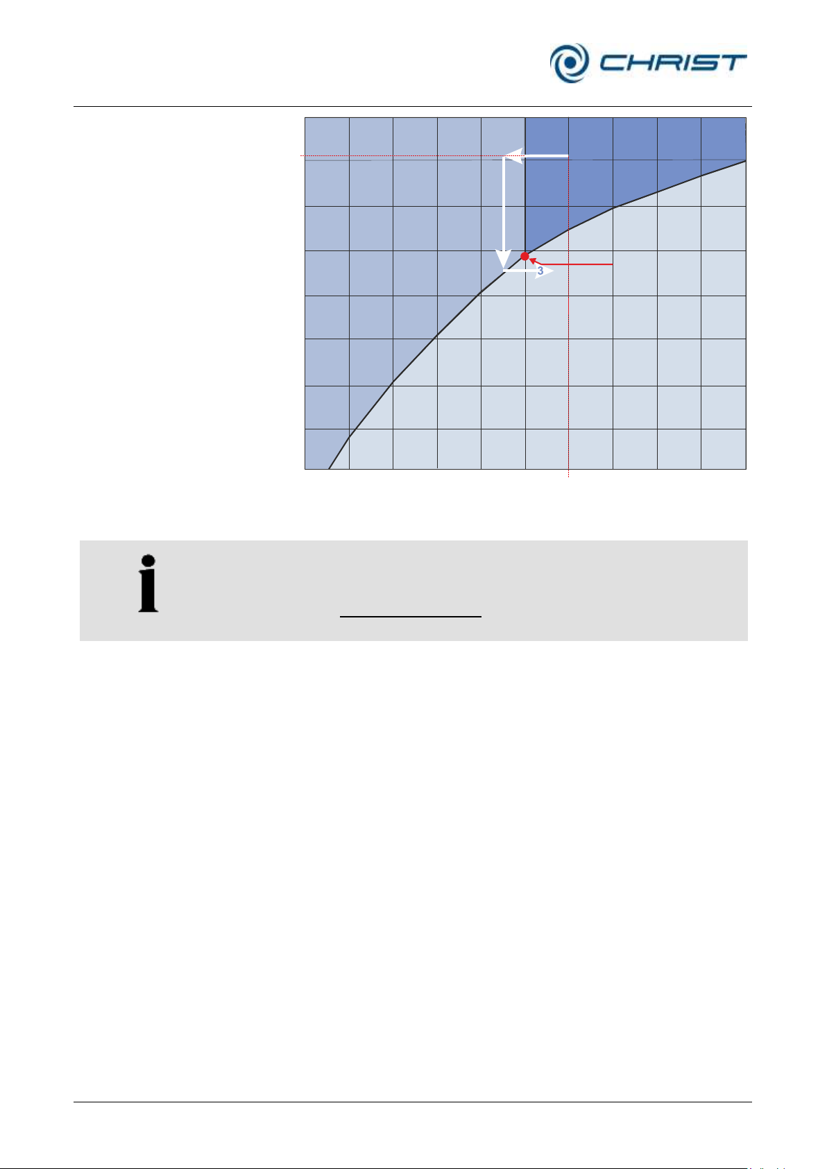
From a physical point of view, the freeze-drying process covers three
phases (see figure below):
(1) Freezing: The product to be dried is frozen under atmospheric pressure.
This can be done either directly in the freeze-dryer or in a separate deepfreeze. The freezing temperature should be approximately 10°C below the
solidification point of the product.
(2) Evacuation: When the product is sufficiently frozen, the vacuum pump is
activated. The pressure inside the drying chamber will be lowered to the
value that corresponds to the freezing temperature in accordance with the
vapour pressure curve above ice.
(3) Sublimation: Thermal energy is added to the product, thus starting the
sublimation process. Due to the added energy, the water in the product is
converted into water vapour. Since the ice condenser is much colder than
the product that is to be dried, the vapour pressure in the ice condenser is
considerably lower than above the product. As a result, the water vapour
that is released by the product streams to the ice condenser, where it
condenses on the condenser coils.
Once the free water has been extracted from the product during the main
drying phase, the last traces of bound water will also be removed at a final
pressure that is as low as possible and at higher temperatures. This takes
place by way of desorption. This drying phase is also called final drying.
Page 16
Freeze-dryer Alpha 1-4 LSCplus
Freeze-dryer Alpha 2-4 LSCplus
2 Layout and mode of operation
16 / 131
Version 01/2011, Rev. 2.3 of 03/07/2017 • sb
Translation of the original operating manual
NOTE
Please find further information about basic principles, optimum procedures
and applications in the brochure "Smart freeze-drying", which can be
downloaded at www.martinchrist.de [Applications] [Lyophilisation].
1
2
1 bar
20°C
V
a
p
o
u
r
p
r
e
s
s
u
r
e
c
u
r
v
e
V
a
p
o
u
r
p
r
e
s
s
u
r
e
c
u
r
v
e
f
o
r
i
c
e
=
s
u
b
l
i
m
a
t
i
o
n
p
r
e
s
s
u
r
e
c
u
r
v
e
Triple point
SOLID
LIQUID
GASEOUS
M
e
l
t
i
n
g
p
o
i
n
t
p
r
e
s
s
u
r
e
c
u
r
v
e
Pressure
(mbar)
Temperature (°C)
Fig. 8: Freeze-drying phases
Page 17

Freeze-dryer Alpha 1-4 LSCplus
Freeze-dryer Alpha 2-4 LSCplus
2 Layout and mode of operation
Version 01/2011, Rev. 2.3 of 03/07/2017 • sb
17 / 131
Translation of the original operating manual
2.2.2 Freeze-drying process
The main components of a freeze-dryer are:
• vacuum drying chamber with a temperature control system for adding
thermal energy
• vacuum pump for generating a vacuum inside the drying chamber
• ice condenser for binding the water vapour that is released by the
2.2.2.1 Preparation
2.2.2.2 Freezing
product.
The ice condenser chamber must be clean and dry. Any water residues
from a preceding drying run must be removed.
The media drain valve and the aeration valve must be closed.
In the case of units that are equipped with a pressure control valve
(standard on LSCplus units), the vacuum pump should be warmed up
(“warm-up”) for at least 15 minutes prior to the start of the main drying
phase. Do not subject the vacuum pump to condensable gases until the
operating temperature is reached. In this way, the service life of the
vacuum pump can be extended.
At the same time, the ice condenser is pre-cooled ("cool-down"). The ice
condenser temperature does not have any influence on the product
temperature. The sole purpose of the ice condenser is to bind the released
water vapour.
First, the product that is to be dried is frozen. This can be carried out either
directly in the freeze-dryer or in a separate deep-freeze. Especially in the
case of small filling quantities, we recommend pre-cooling the shelves as
well in order to prevent the product from thawing during the evacuation.
Two very different structures of the frozen material can be distinguished:
• crystalline structures with clearly distinguishable crystals
• amorphous structures with no crystal junctions at all (e.g. glass)
The majority of the freeze-drying products have a crystalline form.
When freezing these kinds of products, one must take into consideration
that too deep and too quick freezing leads to smaller ice crystals, which has
a negative effect on the duration of the drying process.
For every product to be dried, the solidification point must be determined as
a first step. This is the point at which the water that is contained in the
product has completely crystallised. In order to ensure an optimum freezedrying process, the product temperature should be approximately 10°C
below the solidification point.
A layer thickness of the product of 1-2 cm should not be exceeded, since
otherwise the drying duration would be negatively affected. If liquids are to
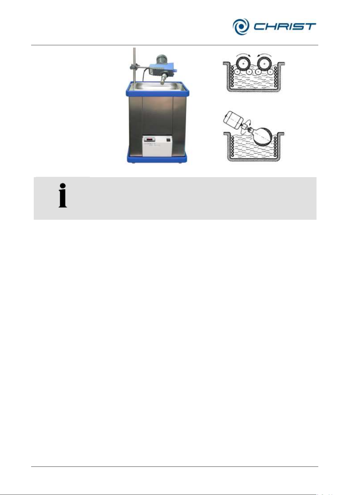
be dried in bottles with a layer thickness of more than 1 cm, we recommend
freezing them in a cooling bath with the aid of a shell or spin freezing
device (see figure). Due to the centrifugal force, the liquid to be frozen will
rise on the inner wall of the bottle and freeze. This procedure reduces the
layer thickness and, thereby, the total drying time will be shortened to a
considerable extent (see figures on the right side).
Page 18
Freeze-dryer Alpha 1-4 LSCplus
Freeze-dryer Alpha 2-4 LSCplus
2 Layout and mode of operation
18 / 131
Version 01/2011, Rev. 2.3 of 03/07/2017 • sb
Translation of the original operating manual
Fig. 9: Shell freezing
Fig. 10: Cooling bath with spin freezing device
Fig. 11: Spin freezing
NOTE
If the product that is to be dried contains solvents or high salt
concentrations, it may start to thaw during the drying process, which is
indicated by clearly visible foaming. In order to prevent this, the product
must be frozen as deeply as possible, e.g. with the aid of liquid nitrogen,
prior to putting it into the unit.
2.2.2.3 Main drying
When the product is frozen to a sufficiently deep extent, the main drying
phase commences. The vacuum pump is switched on. The pressure inside
the drying chamber will be lowered to the value that corresponds to the
freezing temperature in accordance with the vapour pressure curve above
ice. At the same time, thermal energy will be added to the product. In the
case of products in round-bottom flasks, wide-neck bottles, etc., this is
realised through the environment that is considerably warmer (direct
contact heat), in the case of unheated shelves by way of thermal radiation
from the environment, and in the case of temperature-controlled shelves
directly via the shelves. As a result, the sublimation process starts.
At the beginning of the drying process, the maximum drying rate will be
reached. The more the sublimation area recedes into the product, the
further the produced water vapour must pass through the layers that have
already been dried.
Under certain conditions, it is possible that the vacuum inside the ice
condenser chamber increases during the main drying phase (e.g. from 0.63
mbar to 0.47 mbar) although the valve towards the vacuum pump is closed.
From a physical point of view, this is due to the pumping effect of the ice
condenser ("cryo-pumping effect").
The required drying time depends strongly on the drying vacuum. At 1.0
mbar, one gram of ice takes up a volume of 1 m3 of vapour, at 0.1 mbar a
volume of 10 m3 of vapour, and at 0.001 mbar a volume of 100 m3. The
closer the vacuum is to the solidification point, the smaller is the resulting
vapour volume. The drying rate increases and the drying time decreases.
The end of the main drying phase is reached, when the product
temperature and the shelf temperature are nearly identical. The
Page 19

Freeze-dryer Alpha 1-4 LSCplus
Freeze-dryer Alpha 2-4 LSCplus
2 Layout and mode of operation
Version 01/2011, Rev. 2.3 of 03/07/2017 • sb
19 / 131
Translation of the original operating manual
temperature difference between the shelf and the product should be
approximately 3 K to 5 K.
2.2.2.4 Final drying
Final drying is an option whenever one requires a product with minimal
residual moisture. In the physical sense, this process is a desorption
process, i.e. the removal of adsorptively bound water. Final drying is
performed under the lowest possible final pressure that depends on the ice
condenser temperature in accordance with the vapour pressure curve
above ice as well as on the final vacuum of the vacuum pump that is used.
The process is supported by a higher shelf temperature.
2.2.2.5 End of drying and aeration
The end of the drying process is reached when both the product and shelf
temperature are clearly in the positive range (+15 to +20°C) and if their
difference is not greater than 5 K.
Another indication of the end of the drying process is the behaviour of the
vacuum and of the ice condenser temperature. The ice condenser is no
longer subject to load and reaches the final temperature of approximately 55°C or -85°C. The pressure in the drying chamber decreases in
accordance with the ice condenser temperature.
The vacuum pump will be switched off and the drying chamber will be
aerated via a rubber valve or via the aeration valve. The aeration valve can
also be used to flood the unit with nitrogen or another inert gas instead of
ambient air.
Then, the product can be removed from the unit.
2.2.2.6 Defrosting
Defrosting with hot gas
As standard, the freeze-dryer is equipped with a hot-gas defrosting system.
In order to defrost the ice condenser, heated refrigerant is fed through the
heating coil. In addition, the bottom of the ice condenser chamber is heated
by way of a heating collar.
In order to avoid damage, the condensate must be drained off through the
media drain valve directly after the completion of the defrosting process.
Then, any residual water must be removed from the ice condenser
chamber by way of a cloth.
Page 20
Freeze-dryer Alpha 1-4 LSCplus
Freeze-dryer Alpha 2-4 LSCplus
3 Safety
20 / 131
Version 01/2011, Rev. 2.3 of 03/07/2017 • sb
Translation of the original operating manual
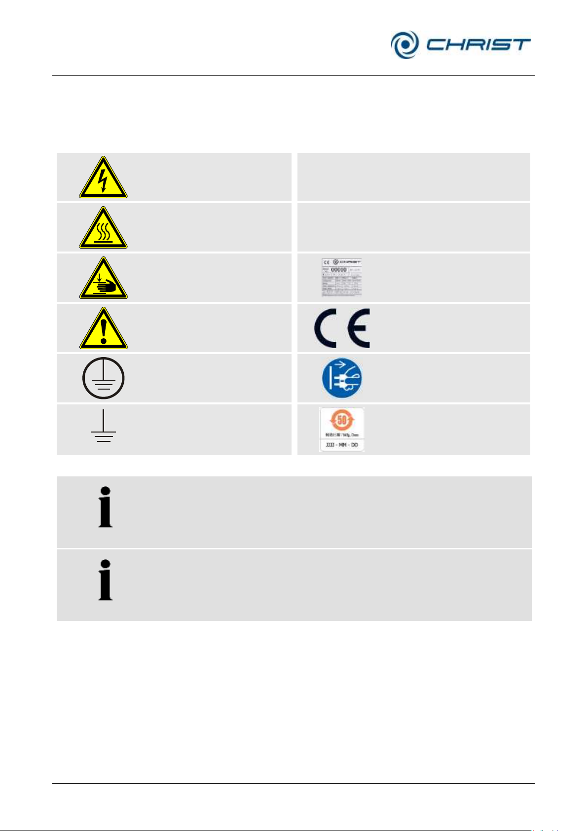
Dangerous voltage
I
On (Power)
Hot surface
0
Off (Power)
Caution! Risk of bruising
Name plate (see chapter
2.1.2 - "Name plate")
Attention, consult the
operating manual
CE mark in compliance
with the directive
2006/42/EC
Protective earth (ground)
Unplug the mains plug
Earth (ground)
China RoHS 2 mark
(only for China)
NOTE
Safety indications on the freeze-dryer must be kept readable at all times.
If necessary, they must be replaced.
NOTE
Not all of the symbols/labels are used for this type of freeze-dryer.
3 Safety
3.1 Marking of the unit
The following symbols are used for CHRIST freeze-dryers:
Page 21

Freeze-dryer Alpha 1-4 LSCplus
Freeze-dryer Alpha 2-4 LSCplus
3 Safety
Version 01/2011, Rev. 2.3 of 03/07/2017 • sb
21 / 131
Translation of the original operating manual
DANGER
This symbol stands for a direct hazard to the life and health of persons.
Non-observance of these symbols causes serious health problems up to
life-endangering injuries.
DANGER
This symbol stands for a direct hazard to the life and health of persons
due to electrical voltage.
Non-observance of these symbols causes serious health problems up to
life-endangering injuries.
WARNING
This symbol stands for a potential hazard to the life and health of persons.
Non-observance of these symbols can cause serious health problems up
to life-endangering injuries.
CAUTION
This symbol indicates a potentially hazardous situation
Non-observance of these notes can cause minor injuries or damage to
property.
NOTE
This symbol indicates important information.
3.2 Explanation of the symbols and notes
This operating manual uses the following names and symbols to indicate
hazards:
Page 22

Freeze-dryer Alpha 1-4 LSCplus
Freeze-dryer Alpha 2-4 LSCplus
3 Safety
22 / 131
Version 01/2011, Rev. 2.3 of 03/07/2017 • sb
Translation of the original operating manual
3.3 Responsibility of the operator
The operator is obliged to ensure that the persons working with the freezedryer
• are 18 years old or older,
• have been specifically ordered to operate the unit and made aware of
dangers originating from the freeze-dryer, supply media, starting and
end products by the operator,
• are familiar with the fundamental regulations concerning workplace
safety and accident prevention
• have read and understood this operating manual (and in particular the
safety sections and warning notes) and confirmed this with their
signature.
The areas of responsibility of the personnel concerning the operation,
maintenance, and care of the unit must be clearly defined.
The safety-conscious work of the personnel in compliance with the
operating manual and the relevant EC and national health and safety
regulations as well as with the accident prevention regulations must be
checked at regular intervals (e.g. every month).
The operator is responsible for performing a risk assessment in terms of
disasters (e. g. fire) in the working area and, if necessary, for taking
constructional measures.
The operator is responsible to check the chemical compatibility of all
substances to be used inside the freeze-dryer (product to be processed,
cleaning media, etc.) with the material of the chamber walls, shelves, pipes,
and gaskets. Substances that may damage the material an degrade the
mechanical strength must not be used.
The freeze-dryer has to be maintained regularly (see chapter 8 "Maintenance and service").
Components that are not in a perfect state must be replaced immediately.
3.4 Operating personnel
It must be ensured that persons operating the unit
• are 18 years old or older,
• have been specifically ordered to operate the unit and made aware of
dangers originating from the freeze-dryer, supply media, starting and
end products by the operator,
• be familiar with the fundamental regulations concerning workplace
safety and accident prevention
• have been trained in terms of the operation of this unit, and
• have read and understood this operating manual (and in particular the
safety sections and warning notes) and confirmed this with their
signature.
Page 23

Freeze-dryer Alpha 1-4 LSCplus
Freeze-dryer Alpha 2-4 LSCplus
3 Safety
Version 01/2011, Rev. 2.3 of 03/07/2017 • sb
23 / 131
Translation of the original operating manual
WARNING
• Ensure that the freeze-dryer was set up and connected properly (see
chapter 5 - "Set-up and connection").
• Connections to customer-provided pipes must be force- and torque-
free.
• Maintain a safety distance of at least 30 cm (12 inches) around the
freeze-dryer.
• Do not store any dangerous goods in the safety area of the freeze-
dryer.
• Do not stay in the safety area longer than what is absolutely necessary
for the operation of the freeze-dryer.
• Only use accessories that have been approved by the manufacturer
(except for commercial vessels made of glass or synthetic materials).
We explicitly warn against the use of equipment of poor quality.
Breaking glass or bursting vessels can cause dangerous situations.
• Observe the instructions on the installation of accessories (see the
separate document).
3.5 Informal safety instructions
This operating manual is a part of the product.
• The operating manual must be kept at the location of use of the freeze-
dryer. Ensure that it is accessible at all times.
• The operating manual must be handed over to any subsequent owner
or operator of the freeze-dryer.
• Any changes made must be added to the operating manual.
• In addition to the operating manual, the general and local rules and
regulations concerning the prevention of accidents and the protection of
the environment must also be supplied.
• Safety and danger indications on the freeze-dryer must be kept
readable at all times. If necessary, they must be replaced.
3.6 Safety instructions
The following instructions must be observed prior to every drying process:
Page 24

Freeze-dryer Alpha 1-4 LSCplus
Freeze-dryer Alpha 2-4 LSCplus
3 Safety
24 / 131
Version 01/2011, Rev. 2.3 of 03/07/2017 • sb
Translation of the original operating manual
DANGER
• Ensure that the local mains voltage matches the nominal voltage that is
stated on the name plate.
• Do not place any dangerous material, e.g. glass vessels containing
liquid substances, within the safety area of 30 cm around the freezedryer. Spilled liquids may get into the freeze-dryer and damage the
electrical or mechanical components.
• Work on the power supply system must only be performed by certified
electricians.
• Inspect the electrical equipment of the unit regularly. Defects such as
loose or burnt cables must be eliminated immediately.
WARNING
• Do not use the freeze-dryer if it was installed incorrectly.
• Do not use the freeze-dryer without panels.
• Do not use the freeze-dryer with accessories that shows signs of
damage.
• Only use the freeze-dryer with accessories that have been approved by
the manufacturer. In case of doubt, contact the manufacturer (see
chapter 7.3 - "Service contact").
• Do not hit or move the freeze-dryer during its operation.
• Do not lean against or rest on the freeze-dryer during its operation.
• Check the freeze-dryer and the accessories before every start-up for
any visible signs of damage.
• Do not dry any substances that could damage the material of the ice
condenser chamber, drying chamber, lid, or accessories in any way,
e.g. highly corrosive substances such as hydrogen chloride (HCl).
• Stop the freeze-dryer immediately in the event of a malfunction.
Eliminate the malfunction (see chapter 7 - "Malfunctions and error
correction") or contact the after-sales service of Firma Martin Christ
Gefriertrocknungsanlagen GmbH (see chapter 7.3 - "Service contact").
• Ensure that all repairs are performed only by authorised and
specialised personnel.
3.6.1 Electrical safety
CHRIST freeze-dryers are units of safety class I. Please comply with the
following points in order to preserve the safety features:
3.6.2 Mechanical safety
In order to ensure the safe operation of the freeze-dryer, please comply
with the following points:
Page 25

Freeze-dryer Alpha 1-4 LSCplus
Freeze-dryer Alpha 2-4 LSCplus
3 Safety
Version 01/2011, Rev. 2.3 of 03/07/2017 • sb
25 / 131
Translation of the original operating manual
DANGER
• Always use fuses of the same type and rating.
• Do not dry explosive or inflammable substances.
• Do not use the freeze-dryer within hazardous locations where there is a
risk of explosion.
DANGER
• Wear suitable protective gloves when installing or removing
accessories. Do not reach into the ice condenser chamber without this
protection – your limbs may freeze onto the chamber walls!
DANGER
• Infectious, toxic, pathogenic, and radioactive substances must be dried
in suitable accessories. Take suitable precautions for your own safety!
• Do not dry products with a high solvent concentration or acidic
products without special protective measures or device-based
precautions (e.g. an additional cooling trap to protect the vacuum
pump). It is absolutely necessary to consult the manufacturer in these
cases (see chapter 7.3 - "Service contact").
• Special caution is necessary when handling azides, as a dangerous
explosive develops in combination with copper or nonferrous metals! It
is absolutely necessary to contact the manufacturer (see chapter 7.3 "Service contact").
WARNING
• Keep informed about local measures to avoid harmful emissions
(depending on the substances to be dried).
• As personal protective equipment, safety gloves are required for the
use of the freeze-dryer.
The materials to be dried may, however, require additional special
safety measures (e.g. drying of infectious, toxic, radioactive, or
pathogenic substances).
3.6.3 Fire prevention
Fuses protect certain electrical circuits within the freeze-dryer against over-
current conditions.
3.6.4 Thermal safety
During the operation of the freeze-dryer, the ice condenser can reach
surface temperatures of –85°C depending on the power.
3.6.5 Chemical and biological safety
If infectious, toxic, pathogenic, or radioactive substances are intended to be
dried, it is in the responsibility of the user to ensure that all necessary
safety regulations, guidelines, precautions, and practices are adhered to
accordingly.
Page 26

Freeze-dryer Alpha 1-4 LSCplus
Freeze-dryer Alpha 2-4 LSCplus
3 Safety
26 / 131
Version 01/2011, Rev. 2.3 of 03/07/2017 • sb
Translation of the original operating manual
3.7 Safety devices
3.7.1 System check
3.7.2 Earth conductor check
An internal system check system monitors the data transfer and sensor
signals with regard to plausibility. Errors are detected by continuous selfmonitoring of the system. Error messages are displayed in the main
window under "Process & equipment messages" (chapter 6.5.1.1 - "Main
window "Manual"", chapter 7.2 - "Process and error messages").
For the earth conductor check, there is an equipotential bonding screw on
the rear panel of the freeze-dryer. An earth conductor check can be carried
out with the aid of a suitable measuring instrument.
3.8 Procedures in the event of hazards and accidents
Hazardous electrical incident:
• Set the control switch to the "0" position in order to interrupt the power
supply completely.
Fire:
• A fire in the electrical control system must be extinguished with a CO2
fire extinguisher!
• Burning oil must be extinguished with a CO2 fire extinguisher or powder
fire extinguisher!
Electric shock:
• While ensuring your own safety, interrupt the circuit as quickly as
possible (control switch). Keep the affected persons warm and calm.
Get medical attention immediately! Check consciousness and
breathing continuously. In the case of unconsciousness of lack of
normal breathing, perform cardiopulmonary resuscitation (CPR).
Burns:
• Cool small-area burns (e.g. finger) immediately with cold water for
approximately 2 minutes.
• Do not cool if larger areas of the body surface are burnt since there is a
risk of hypothermia.
• Cover the burns loosely and in a sterile manner (e.g. with sterile
dressing).
• Keep the affected persons warm and calm.
IF IN DOUBT, CALL THE EMERGENCY PHYSICIAN (AMBULANCE)!
Page 27

Freeze-dryer Alpha 1-4 LSCplus
Freeze-dryer Alpha 2-4 LSCplus
3 Safety
Version 01/2011, Rev. 2.3 of 03/07/2017 • sb
27 / 131
Translation of the original operating manual
3.9 Remaining hazards
All CHRIST freeze-dryers were built state-of-the-art and according to the
accepted safety rules. Danger to life and limb of the operator, or of third
parties, or impairments of the units or other material assets, however,
cannot be completely excluded when the units are being used.
Use the freeze-dryer
• only for the purpose that it was originally intended for (see chapter 1.2 -
"Intended use") and
• only if it is in a perfect running state.
• Immediately eliminate any problems that can affect safety.
Page 28

Freeze-dryer Alpha 1-4 LSCplus
Freeze-dryer Alpha 2-4 LSCplus
4 Storage and transport
28 / 131
Version 01/2011, Rev. 2.3 of 03/07/2017 • sb
Translation of the original operating manual
Alpha 1-4 LSCplus
Alpha 2-4 LSCplus
Height:
415 mm
415 mm
Width:
390 mm
390 mm
Depth:
555 mm + 80 mm vacuum connection
555 mm + 80 mm vacuum connection
Weight:
approx. 48 kg
approx. 60 kg
4 Storage and transport
4.1 Dimensions and weight
4.2 Storage conditions
Values for the freeze-dryer without a vacuum pump:
In order to ensure the protection against mechanical and climatic
influences, the guidelines of the German Federal Association for Wooden
Packages, Pallets, and Export Packaging (Bundesverband Holzpackmittel,
Paletten, Exportverpackung e.V.), the so-called HPE packaging guidelines,
must be applied when packing and storing the freeze-dryer.
The storage must be:
• dust-free
• dry
• free from excessive temperature fluctuations
• free from a mechanical load.
Page 29
Freeze-dryer Alpha 1-4 LSCplus
Freeze-dryer Alpha 2-4 LSCplus
4 Storage and transport
Version 01/2011, Rev. 2.3 of 03/07/2017 • sb
29 / 131
Translation of the original operating manual
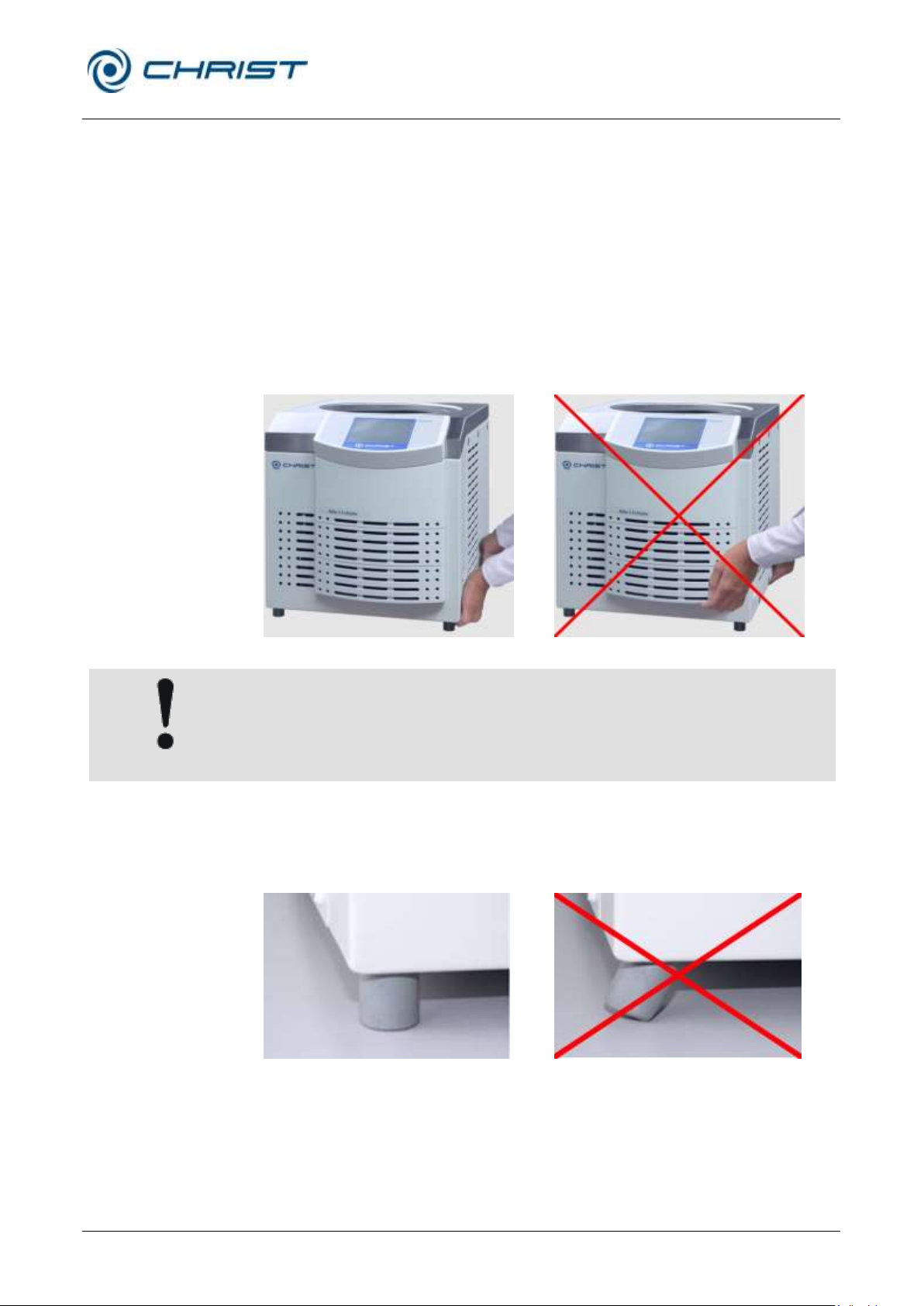
correct
incorrect
CAUTION
The freeze-dryer Alpha 1-4 LSCplus weighs approx. 48 kg!
The freeze-dryer Alpha 2-4 LSCplus weighs approx. 60 kg!
correct
incorrect
4.3 Notes on transport
• Use suitable packaging for the transport, and if at all possible, the
original packaging.
• Install all transport safety devices (see chapter 4.5 - "Transport safety
device").
• Over short distances, the freeze-dryer can be transported by a suitable
number of persons who reach under it from the sides.
• When lifting the freeze dryer, always reach under the freeze-dryer from
the side. Do not grab the unit at the plastic control panel (see figures
below).
Fig. 12: Lifting the freeze-dryer
• When setting the unit down, ensure that the feet are upright (see figures
below).
Fig. 13: Unit feet
Page 30

Freeze-dryer Alpha 1-4 LSCplus
Freeze-dryer Alpha 2-4 LSCplus
4 Storage and transport
30 / 131
Version 01/2011, Rev. 2.3 of 03/07/2017 • sb
Translation of the original operating manual
CAUTION
The freeze-dryer Alpha 1-4 LSCplus weighs approx. 48 kg!
The freeze-dryer Alpha 2-4 LSCplus weighs approx. 60 kg!
NOTE
Prior to any transport, the vacuum sensor must be deinstalled.
4.4 Packaging
The freeze-dryer is packaged in a cardboard box or in a wooden crate,
depending on the scope of supply.
• After opening the packaging, take out the box containing the
accessories.
• Remove the packaging material.
• Lift the freeze-dryer upwards and out of the crate/cardboard box. When
lifting the unit, always reach under the freeze-dryer from the side.
• Retain the packaging for any possible future transport of the freeze-
dryer.
4.5 Transport safety device
Prior to start-up, the vacuum sensor must be installed (see chapter 5.5 "Vacuum sensor").
Page 31

Freeze-dryer Alpha 1-4 LSCplus
Freeze-dryer Alpha 2-4 LSCplus
5 Set-up and connection
Version 01/2011, Rev. 2.3 of 03/07/2017 • sb
31 / 131
Translation of the original operating manual
NOTE
Refrigeration problems of the freeze-dryer are often caused by insufficient
conditions at the location of use. This is why compliance with the following
conditions is absolutely mandatory!
5 Set-up and connection
5.1 Installation site
Operate the freeze-dryer only in closed and dry rooms.
• The table must be stable and have a solid, even tabletop.
• Ensure sufficient ventilation. Do not place any paper, cloth, or similar
material behind or under the unit, since otherwise the air circulation will
be impaired.
• Keep a safety distance of at least 30 cm around the freeze-dryer so that
the vents in the unit remain fully effective.
• The ambient temperature must be in the range of +10°C to +25°C. A
potential night-time setback of the air conditioning system must be
taken into consideration.
• Prevent the room temperature from rising, for example due to closed
doors at night.
• Do not subject the freeze-dryer to thermal stress, e.g. by positioning it
near heat generators.
• Prevent thermal overload, e.g. caused by other equipment in the direct
vicinity of the freeze-dryer.
• Do not set up the vacuum pump directly next to the heat exchanger
(condenser).
• In the case of water-cooled systems, ensure that the water circuit
provides a sufficient amount of cooling water.
• Avoid direct sunlight (UV radiation).
Page 32

Freeze-dryer Alpha 1-4 LSCplus
Freeze-dryer Alpha 2-4 LSCplus
5 Set-up and connection
32 / 131
Version 01/2011, Rev. 2.3 of 03/07/2017 • sb
Translation of the original operating manual
DANGER
The operating voltage on the name plate must correspond to the local
supply voltage
NOTE
The ice condenser chamber can be flooded with nitrogen via the hose
nozzle of the aeration valve.
5.2 Power supply
5.2.1 Connection
CHRIST freeze-dryers are units of safety class I.
Alpha 1-4 LSCplus and Alpha 2-4 LSCplus units have a three-wire
power cord with a fixed cable(see chapter 10 - "Technical data").
An equipotential bonding screw is located on the back below the mains
power input (see chapter 2.1.1 - "Functional and operating elements"). This
equipotential bonding screw can be used to perform an earth conductor
check.
5.2.2 Customer-provided fuses
Typically, the freeze-dryer must be protected with 16 Amp G fuses that are
to be provided by the customer.
5.3 Aeration valve
The aeration valve is located on top of the left side of the unit (see chapter
2.1.1 - "Functional and operating elements").
After the end of a freeze-drying process, the unit will be aerated via the
aeration valve.
5.4 Media drain valve
The media drain valve is located at the bottom of the left side of the unit
(see chapter 2.1.1 - "Functional and operating elements"). It is used to
drain off the condensate and the defrosting water.
• Connect the drain hose (included in the scope of supply) to the hose
connector.
• Place a collecting vessel under the unit.
The hose must be laid with a continuous slope and the end of the hose
must always be above the liquid level in the collecting vessel. This prevents
water and dirt residues from being sucked into the ice condenser chamber
if there is negative pressure when the media drain valve is opened.
Page 33
Freeze-dryer Alpha 1-4 LSCplus
Freeze-dryer Alpha 2-4 LSCplus
5 Set-up and connection
Version 01/2011, Rev. 2.3 of 03/07/2017 • sb
33 / 131
Translation of the original operating manual
NOTE
Please refer to the separate operating manual of the vacuum sensor!
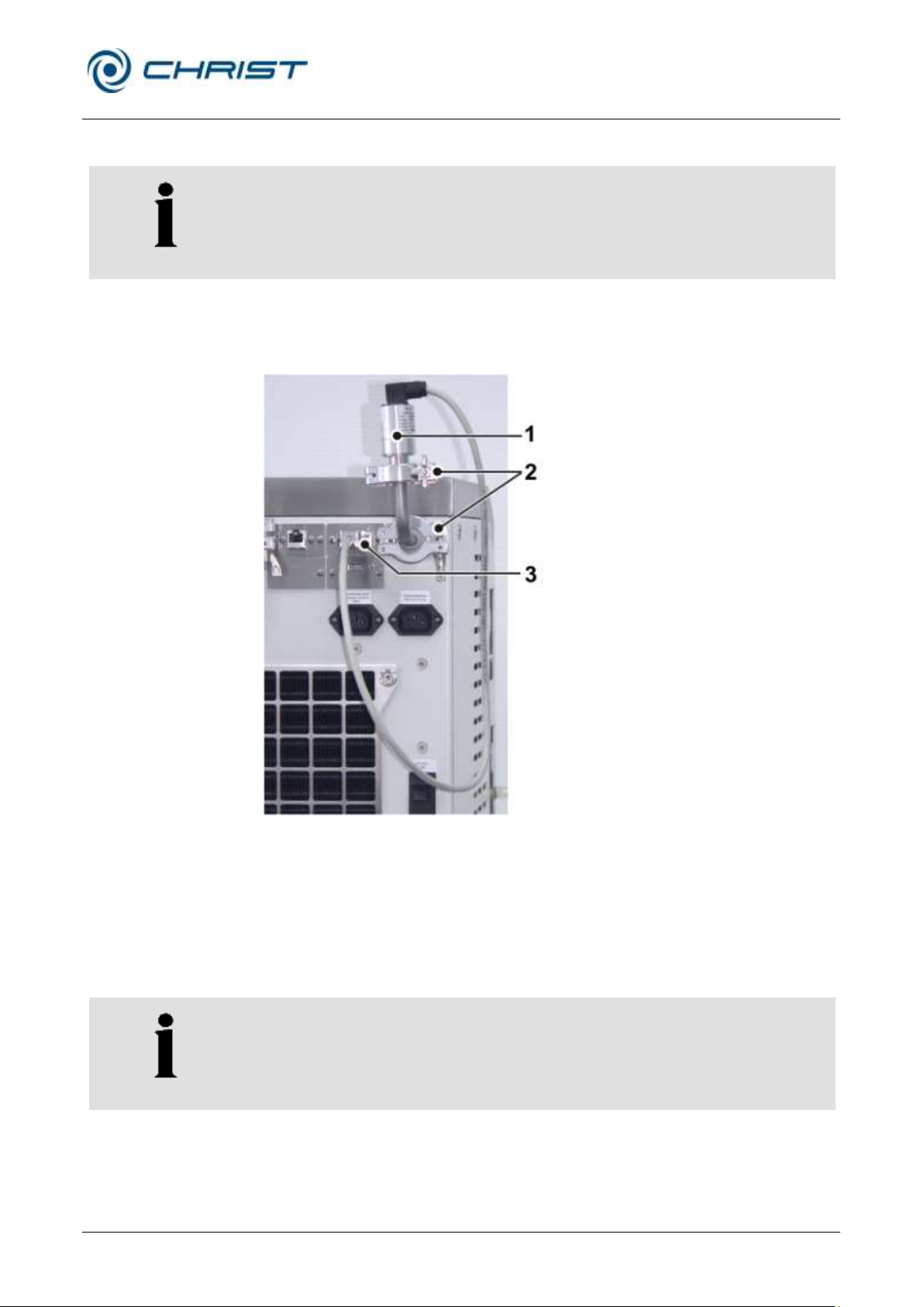
1 Vacuum sensor
2 Clamping rings
3 Connection socket
NOTE
It is absolutely essential to comply with the manufacturer’s instructions in
the separate operating manual of the vacuum sensor!
5.5 Vacuum sensor
In order to protect the vacuum sensor against transport damage, it comes
supplied in its original packaging. Prior to commissioning the freeze-dryer,
the sensor must be installed.
Fig. 14: Position of the vacuum sensor and the connection socket
• Switch the unit off by actuating the mains power switch.
• Take the vacuum sensor out of its original packaging and fasten it to the
connector with a bow-shaped connecting piece, two clamping rings
(DIN16KF) and two centring rings (included in the scope of supply).
• Plug the connector to the connection socket and hand-tighten the
screws on the connector.
Page 34
Freeze-dryer Alpha 1-4 LSCplus
Freeze-dryer Alpha 2-4 LSCplus
5 Set-up and connection
34 / 131
Version 01/2011, Rev. 2.3 of 03/07/2017 • sb
Translation of the original operating manual
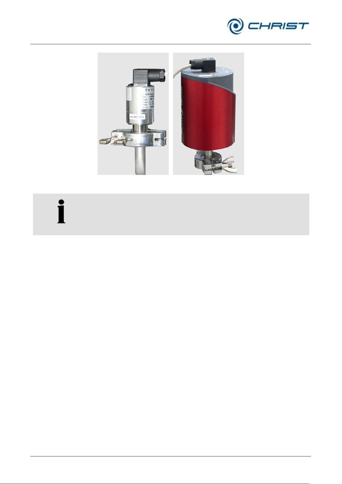
Thyracont VCP63 (Pirani)
Pfeiffer CMR 363 (capacitive)
NOTE
The vacuum sensor comes supplied in a calibrated state.
Fig. 15: Vacuum sensors of different manufacturers
After the freeze-dryer has been switched on, the vacuum sensor needs
several minutes until it is ready for operation.
Page 35
Freeze-dryer Alpha 1-4 LSCplus
Freeze-dryer Alpha 2-4 LSCplus
5 Set-up and connection
Version 01/2011, Rev. 2.3 of 03/07/2017 • sb
35 / 131
Translation of the original operating manual
NOTE
It is absolutely essential to refer to the separate instruction manual of the
vacuum pump and exhaust filter (if applicable)!
NOTE
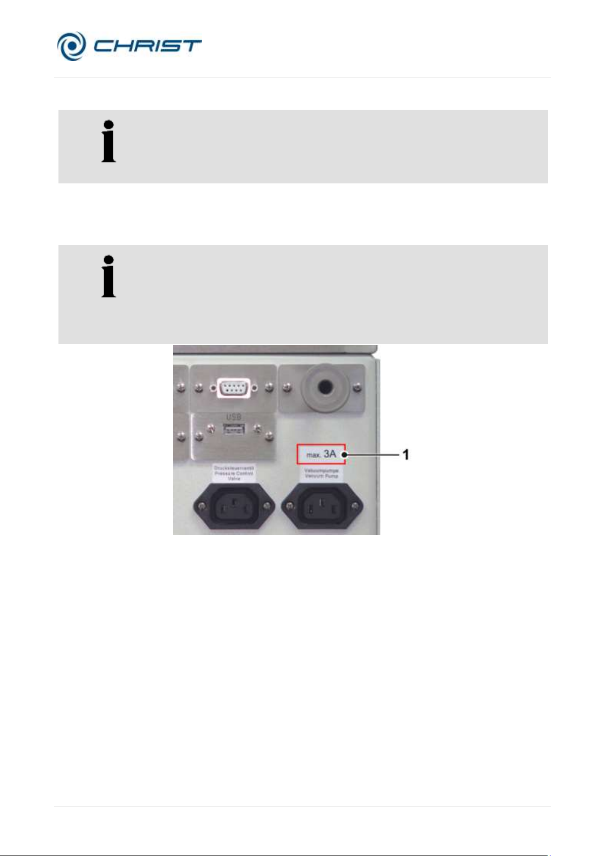
The vacuum pump is supplied with power by the unit, but the maximum
current for the vacuum pump is limited. It is absolutely essential to refer to
the label of the electrical outlet for the vacuum pump (see the following
picture)!
If the current requirement of the vacuum pump is higher than the value that
is stated on the label, the pump must be supplied separately via an on-site
power socket.
1 Label indicating the
maximum current
5.4.6 Vakuumpumpe
5.6 Vacuum pump
The vacuum pump must be connected to the vacuum connection of the unit
and to the electrical socket at the back of the unit, which is marked
accordingly (see chapter 2.1.1 - "Functional and operating elements").
Fig. 16: Indication of the maximum current for the vacuum pump (example)
The oil mist that escapes from the pump during operation must be retained
or discharged via an exhaust filter (oil mist separator).
• We strongly recommend using an oil mist separator. The filter prevents
the contamination of the air with oil mist.
• For discharging the oil mist, connect a suitable hose (RZ-2.5 and RC-6:
½", DUO 5 or DUO 10 ¾") to the exhaust connector of the vacuum
pump.
• The hose line must be laid in such a manner that any condensation
water cannot flow back into the pump. In the case of a rising hose line,
we recommend using a condensate trap (Woulff bottle or wash bottle).
Page 36
Freeze-dryer Alpha 1-4 LSCplus
Freeze-dryer Alpha 2-4 LSCplus
5 Set-up and connection
36 / 131
Version 01/2011, Rev. 2.3 of 03/07/2017 • sb
Translation of the original operating manual
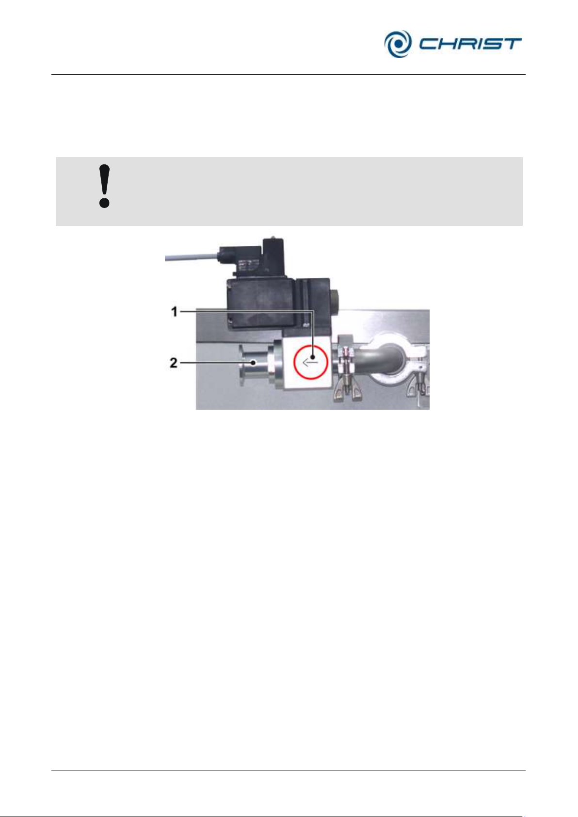
CAUTION
Observe the installation direction of the pressure control valve!
1 Pressure control valve
2 Vacuum pump
connection
5.7 Pressure control valve
The pressure control valve is integrated in the suction pipe between the
vacuum pump and ice condenser chamber. During certain, specified
process phases, it interrupts the volume flow to the vacuum pump (see
chapter 2.2.1 - "General information on freeze-drying").
Fig. 17: Installation of the pressure control valve
Page 37
Freeze-dryer Alpha 1-4 LSCplus
Freeze-dryer Alpha 2-4 LSCplus
5 Set-up and connection
Version 01/2011, Rev. 2.3 of 03/07/2017 • sb
37 / 131
Translation of the original operating manual
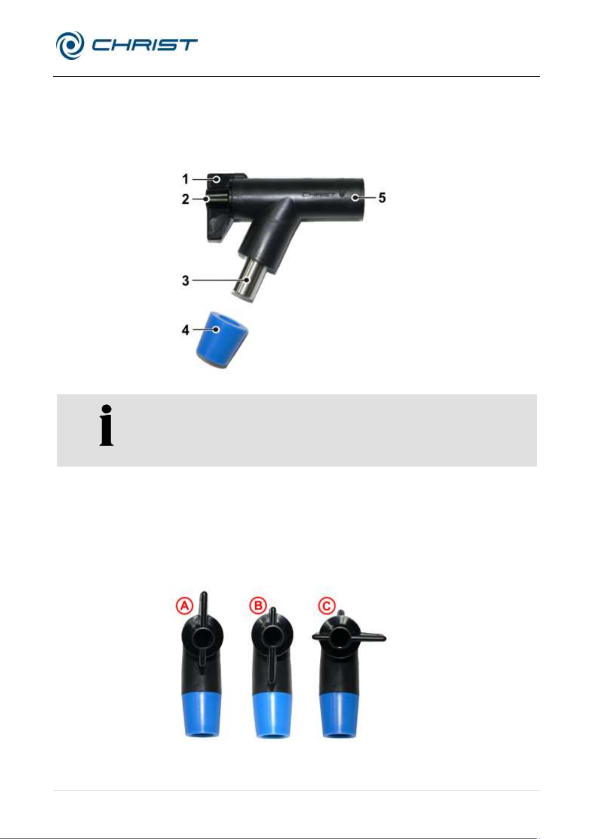
1 Locking handle
2 Aeration connection
3 Vessel connection
4 Rubber plug
5 Connection to freeze-
dryer (e.g. via a
manifold)
NOTE
The rubber valves come supplied in an ungreased state. This is why a thin
layer of vacuum grease must be applied to the connector of the freezedryer as well as to the vessel connector prior to start-up in order to ensure
trouble-free operation.
5.8 Rubber valves
The rubber valves (part no. 121860) enable the connection of round-bottom
flasks, wide-neck filter bottles, or distributors for ampoules to a manifold or
drying chamber. Depending on the connector of the components, the blue
plug can be removed.
Fig. 18: Rubber valve
In position A (see figure below), the aeration connector is open and the
vessel connector is closed. The accessory will be aerated while the vacuum
inside the drying chamber is maintained. As a result, vessels can be
exchanged without any interruption of the drying process.
In position B, the aeration connector is closed and the vessel connector is
open. The connected accessory is connected to the freeze-dryer.
In position C, the aeration connector and the vessel connector are closed.
Fig. 19: Possible positions of the locking handle
Page 38

Freeze-dryer Alpha 1-4 LSCplus
Freeze-dryer Alpha 2-4 LSCplus
6 Operation
38 / 131
Version 01/2011, Rev. 2.3 of 03/07/2017 • sb
Translation of the original operating manual
WARNING
Before the initial start-up, please ensure that your freeze-dryer is properly
set up and installed (see chapter 5 - "Set-up and connection")
6 Operation
6.1 Initial start-up
6.2 Installation of accessories
The accessories must be completed in accordance with the drying method
that is applied as well as in accordance with the scope of supply.
Please contact our sales department if you have any queries.
6.3 Preparation
The ice condenser chamber must be clean and dry.
• Remove any water residues from the preceding run.
• Close the media drain valve and the aeration valve.
• Ensure that all of the valves of the accessories are closed.
• Switch the vacuum pump on.
6.4 Switching the freeze-dryer on
• Actuate the mains switch.
The control unit performs a self-test and an initialisation. This may take
several seconds.
• Follow the safety instructions and hazard warnings (see chapter 3 "Safety")!
Page 39
Freeze-dryer Alpha 1-4 LSCplus
Freeze-dryer Alpha 2-4 LSCplus
6 Operation
Version 01/2011, Rev. 2.3 of 03/07/2017 • sb
39 / 131
Translation of the original operating manual
6.5 LSCplus control system
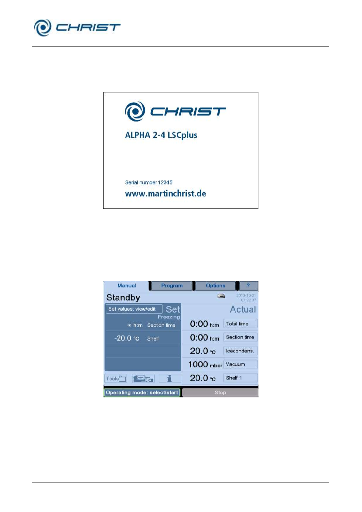
The control system LSCplus (Lyo Screen Control plus) was specifically
developed for the control of freeze-drying processes. The clear user
interface enables the intuitive operation of the unit.
Fig. 20: Start screen of the LSCplus control unit (example)
6.5.1 User interface
The system is operated via a touch panel, i.e. by touching the buttons on
the display. Every button is marked by a frame. Pressing the button
activates the associated function. Depending on the function, a dialog box
opens, a value can be changed, or a transaction can be confirmed.
Fig. 21: Buttons are marked by a frame
Page 40
Freeze-dryer Alpha 1-4 LSCplus
Freeze-dryer Alpha 2-4 LSCplus
6 Operation
40 / 131
Version 01/2011, Rev. 2.3 of 03/07/2017 • sb
Translation of the original operating manual
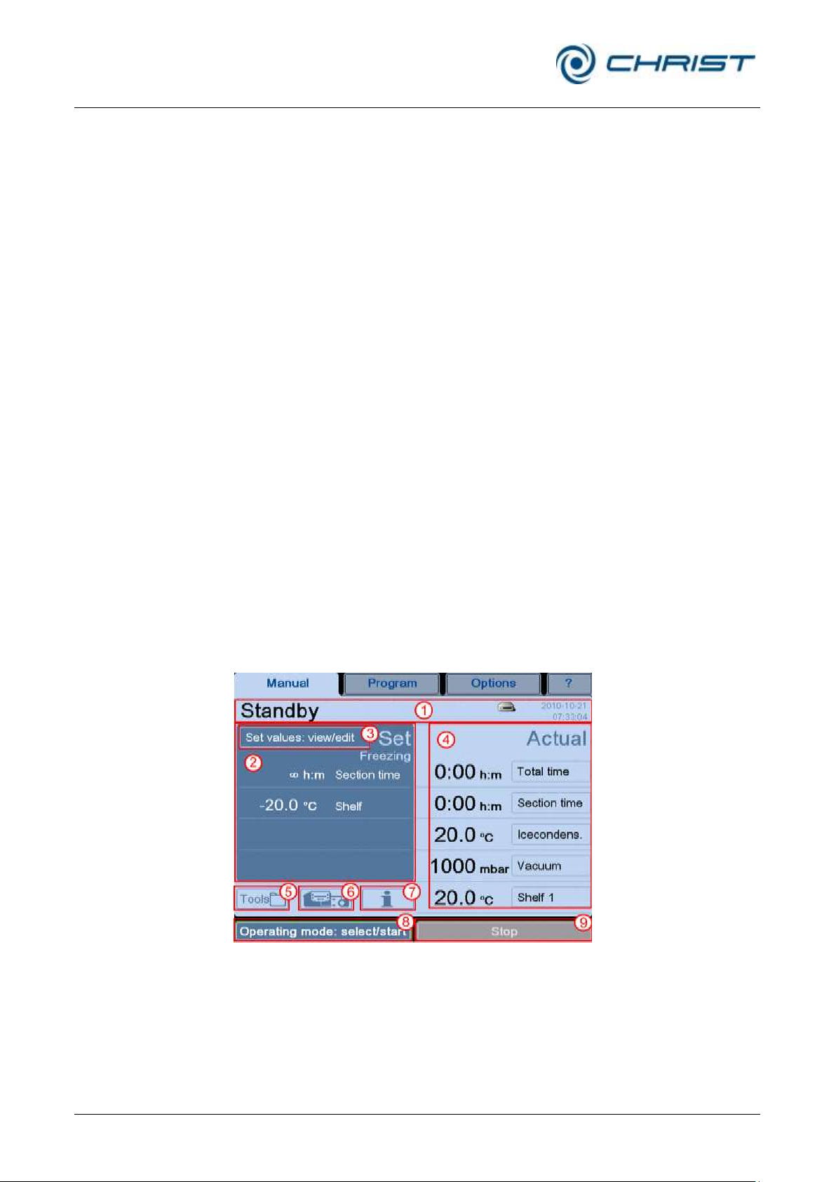
1 Status line
2 Set process values
3 Button "Set values:
view/edit"
4 Actual values of the
current process
5 Button "Tools"
6 Button "Schematic
system diagram"
7 Button "Process- and
equipment messages"
8 Button "Operating
mode: select/start"
9 Button "Stop"
The user interface is divided into four main windows that can be called up
by touching the corresponding buttons:
Manual
This window is also the standard user interface. It is used to control the
freeze-drying process manually.
Program
This area is used to create and execute programs for automating the
freeze-drying process and for making it reproducible. This function is only
available in combination with the programmer module PGMplus option.
Options
This window is used for personalised settings that enable the users to
adapt the system as far as possible to their respective area of activity.
?
In this window, the users can find all of the relevant information concerning
the control system at a glance. In the event of enquiries at the factory,
these data facilitate the assignment and expediting of the processing of the
enquiries.
6.5.1.1 Main window "Manual"
This main window shows all of the relevant process data. Here, the
individual phases of a freeze-drying process can be controlled manually.
Fig. 22: Overview of the main window "Manual"
Page 41
Freeze-dryer Alpha 1-4 LSCplus
Freeze-dryer Alpha 2-4 LSCplus
6 Operation
Version 01/2011, Rev. 2.3 of 03/07/2017 • sb
41 / 131
Translation of the original operating manual
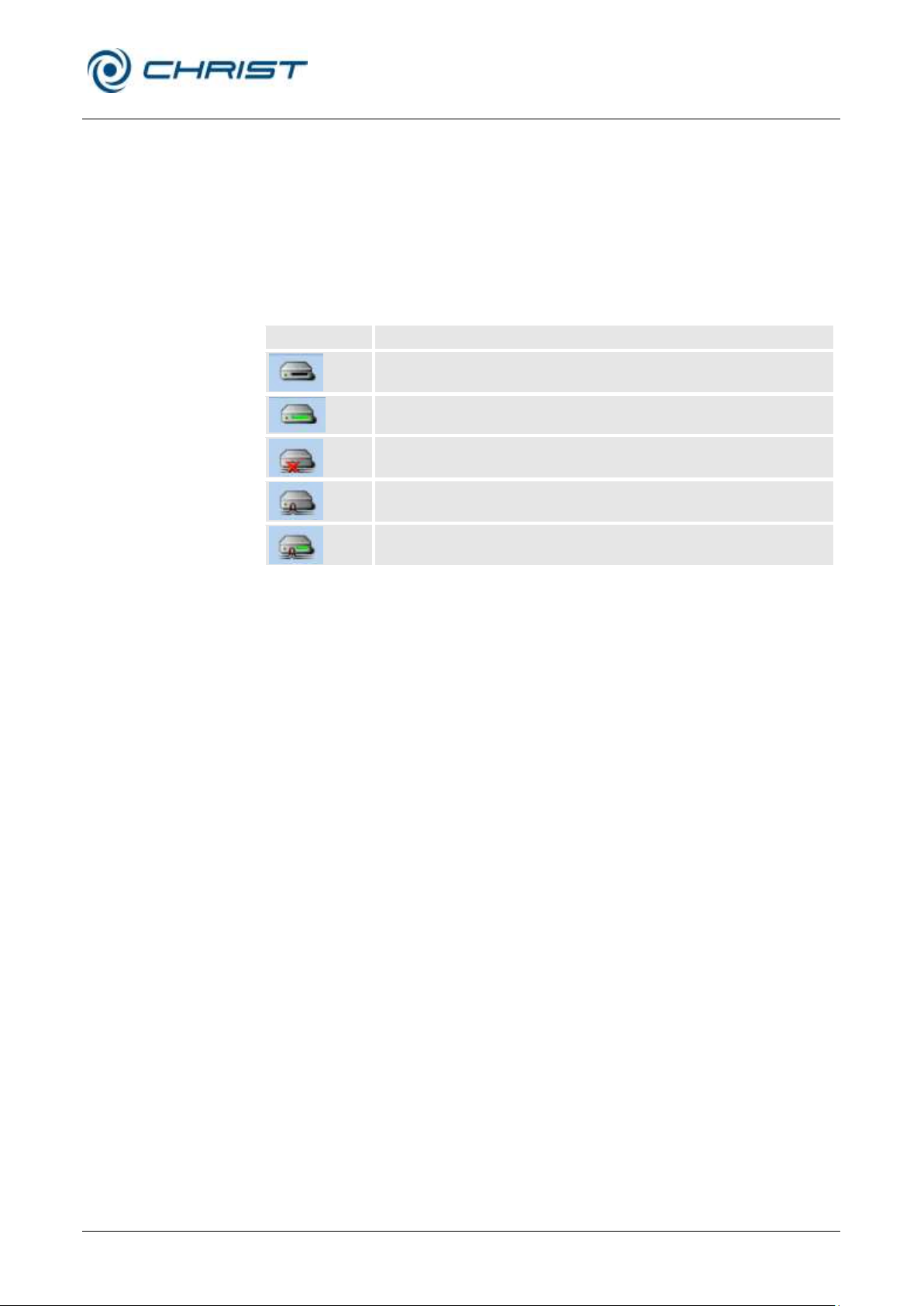
No symbol
No USB storage device or LAN network connected
USB storage device connected
Process recording on a USB storage device active
Network available, but no network drive connected
Network drive connected (e.g. LPCplus, LyoLogplus)
Network drive connected and process recording active
Status line (1)
This line shows the operating status of the freeze-dryer as well as the
active phase.
The status line also shows the current date and time. The clock is batterybuffered and must be reset after a failure (chapter 6.5.1.3 - "Main window
"Options "", section ”Administration”").
In addition, the drive symbol provides information concerning the status of
the external data storage device or of the network drive. The following
...
symbols are possible:
Set process values (2)
In the manual mode, the set values for the individual phases of the freezedrying process must be entered prior to the start of the process. Value
ranges have been saved for the various phases. These value ranges can
be displayed in the input window with the aid of the buttons "min" or "max"
(see chapter 6.5.2.1 - "Entering set values in the manual mode").
Button "Set values: view/edit" (3)
This button is used to call up the various parameters that can be edited.
Page 42
Freeze-dryer Alpha 1-4 LSCplus
Freeze-dryer Alpha 2-4 LSCplus
6 Operation
42 / 131
Version 01/2011, Rev. 2.3 of 03/07/2017 • sb
Translation of the original operating manual
Actual values of the current process (4)
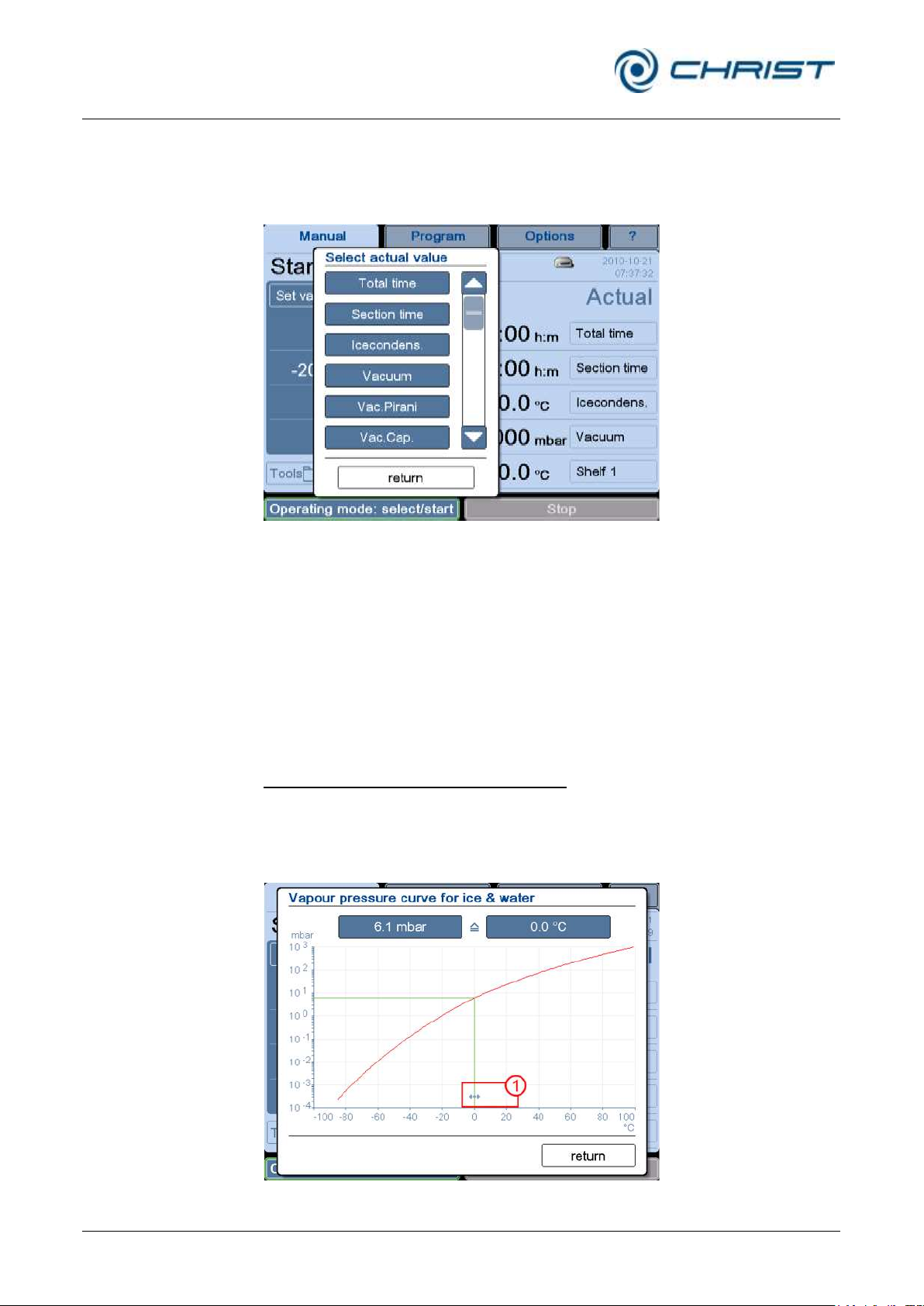
This area shows the current process data. The fields can be configured as
desired:
• Select the button of the field that is to be adapted. A dialog box opens:
Fig. 23: Dialog box "Select actual value"
• Select the desired configuration or quit the dialog box by pressing the
"return" button.
In this way, it is possible to configure a personalised overview of the actual
values.
Dialog box "Tools" (5)
This dialog box is used to call up various aids and resources.
Vapour pressure curve for ice and water
A diagram shows the relationship between the pressure and sample
temperature. The pressure and temperature values can be changed by
pressing the buttons or by moving the arrows (see figure, item 1). The other
value will be adapted automatically.
Fig. 24: Dialog box “Vapour pressure curve for ice and water”
Page 43
Freeze-dryer Alpha 1-4 LSCplus
Freeze-dryer Alpha 2-4 LSCplus
6 Operation
Version 01/2011, Rev. 2.3 of 03/07/2017 • sb
43 / 131
Translation of the original operating manual
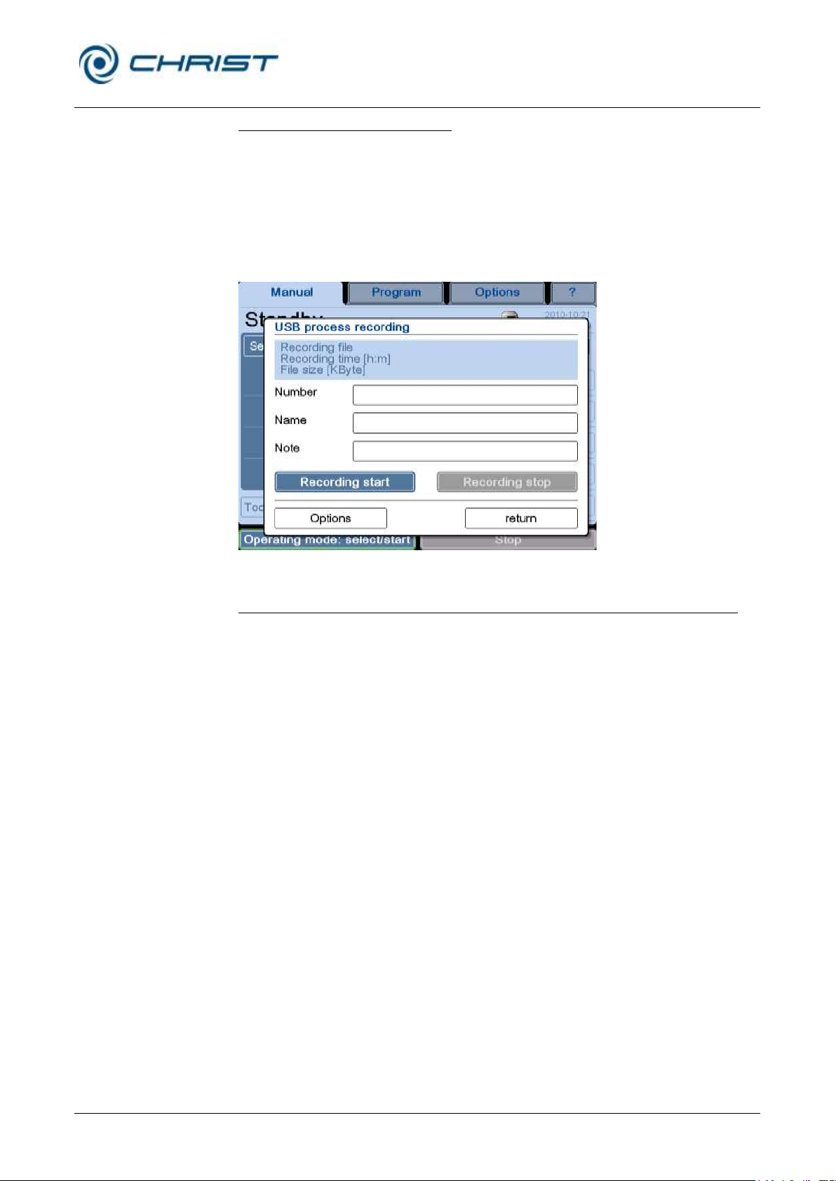
Option: USB process recording (see chapter 6.6 - "Optional extensions")
• Select the "Process recording" function in the dialog box "Tools".
• Select the input fields ("Batch data"). A keyboard for the data input will
be displayed.
• If necessary, select the “Options” tab, choose between manual or
automatic recording, and define a recording interval.
• Press the "return" button in order to close the dialog box.
The process recording will now run in the background.
Fig. 25: Dialog box “USB process recording”
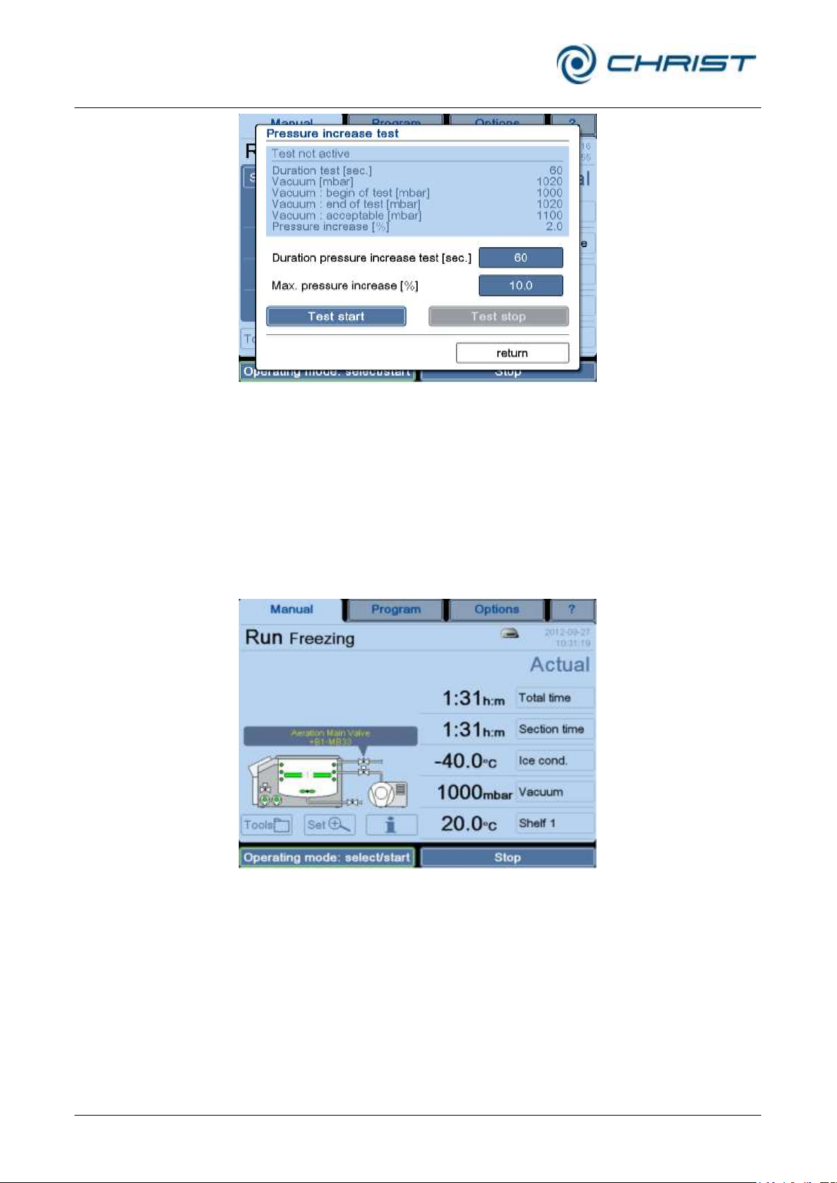
Option: Pressure increase test (only with the double-chamber method)
The pressure increase test can only be performed when the freeze-dryer
is equipped with an intermediate valve. The performance is possible in the
manual mode as well as in the program mode. Additionally, the pressure
increase test can be automatically performed as part of a program (see
chapter 6.5.3.1 - "Creating a program").
• Select "Pressure increase test" in the "Tools" dialog box.
• Enter the set values for the duration and maximum pressure increase
with the aid of the buttons.
• Start the pressure increase test. The test time will be displayed. After
the end of the test, a status message (pressure increase was successful or failed) will be displayed together with the measured values:
Page 44
Freeze-dryer Alpha 1-4 LSCplus
Freeze-dryer Alpha 2-4 LSCplus
6 Operation
44 / 131
Version 01/2011, Rev. 2.3 of 03/07/2017 • sb
Translation of the original operating manual
Fig. 26: Dialog box “Pressure increase test”
• The "Test stop" button stops the pressure increase test.
Dialog box "Schematic system diagram" (6)
Pressing the button "Schematic system diagram" displays a schematic
diagram of the system on the left-hand side of the screen, including all the
components. Active components are displayed in green. Touching a
component calls up its name and reference designator.
Fig. 27: Schematic system diagram with the name and reference designator of the
component
Dialog box "Process and equipment messages" (7)
This dialog box shows and saves all of the error messages and other
messages. In the event of an error or message, the window “Process and
equipment messages” will open automatically. In addition, a sound signal is
emitted until the error is acknowledged.
Page 45
Freeze-dryer Alpha 1-4 LSCplus
Freeze-dryer Alpha 2-4 LSCplus
6 Operation
Version 01/2011, Rev. 2.3 of 03/07/2017 • sb
45 / 131
Translation of the original operating manual
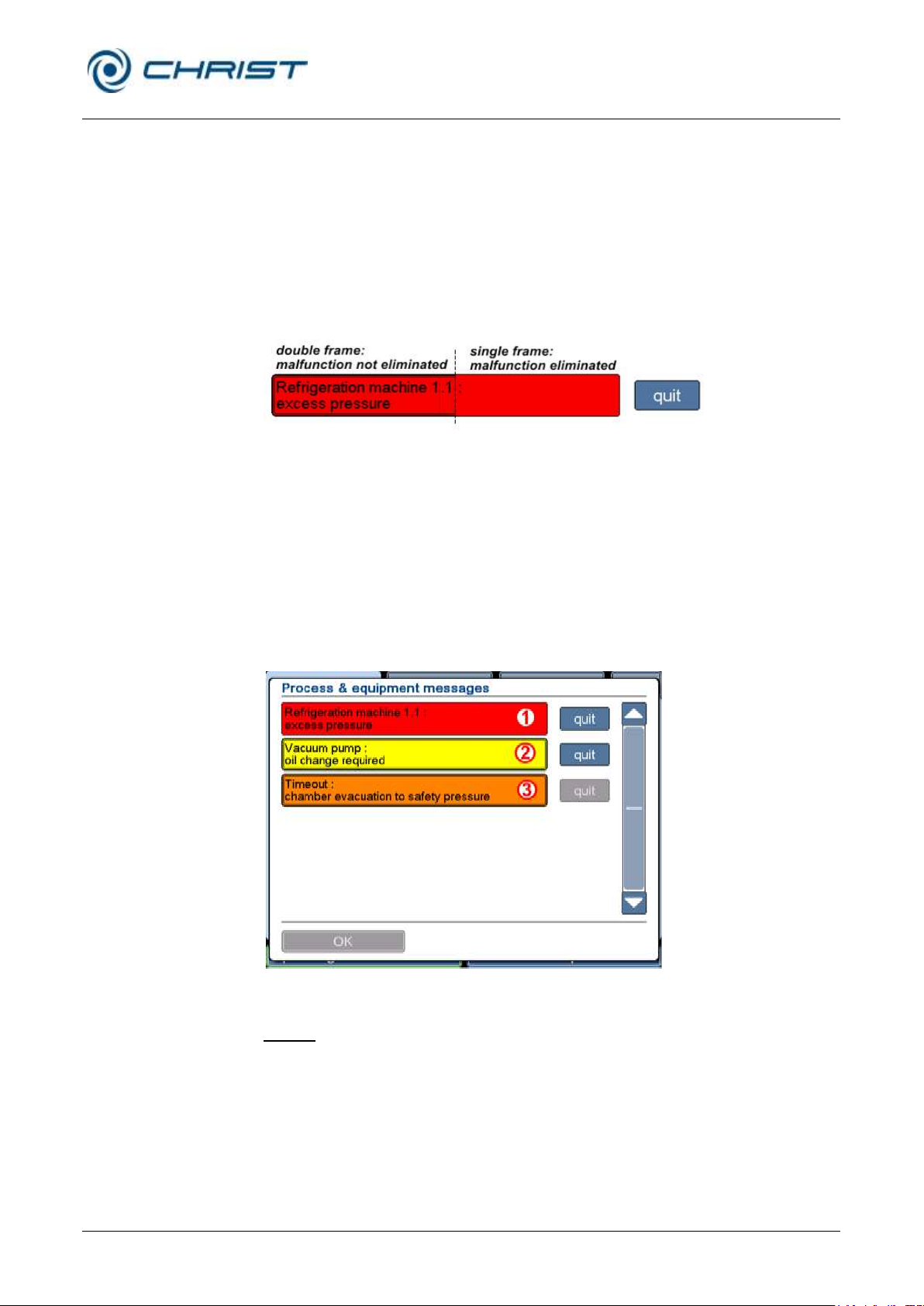
1 The malfunction has
been eliminated, but
the message has not
been acknowledged
yet
2 The malfunction has
not be eliminated and
the message has not
been acknowledged
yet
3 The malfunction has
not been eliminated
yet, but the message
has been
acknowledged
Malfunctions are divided into three categories:
• Red: error messages
• Orange: process messages
• Yellow: general messages
The representation of the message provides information on its current
status. A double frame around a message means that the error has not
been eliminated yet. The colour of the button "quit" changes from blue to
grey once the message has been acknowledged.
Fig. 28: Representation of an error message
The advantage of this system is that malfunctions that occurred during the
night can be discovered the next day even if the cause of the malfunction
has already been eliminated.
The dialog box cannot be quit until all of the messages have been
acknowledged.
If a message has been acknowledged although the malfunction has not
been eliminated, the button "Process and equipment messages" will be
displayed in the respective colour of the malfunction in the main window.
Fig. 29: Dialog box "Process and equipment messages"
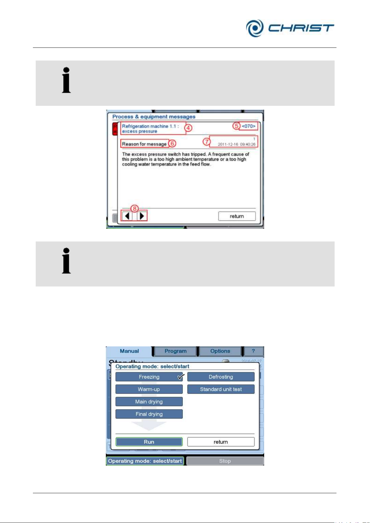
Details
Touching the message calls up details concerning the error message:
• Cause of the message
• Effects of the message
• Measures to eliminate the error
• Reference designator
• Error counter (indicates how often this error has occurred) and the time
stamp of the last error message.
Page 46
Freeze-dryer Alpha 1-4 LSCplus
Freeze-dryer Alpha 2-4 LSCplus
6 Operation
46 / 131
Version 01/2011, Rev. 2.3 of 03/07/2017 • sb
Translation of the original operating manual
NOTE
The error message text is always followed by an error code. Always
indicate the error code in the event of enquiries or service requests!
4 Error message
5 Error code
6 Detailed information
7 Error counter and
time stamp of the last
error
8 Arrow keys
NOTE
The texts of the process and error messages are not included in this
operating manual.
You can order these documents from our service department.
Use the arrow keys to call up the individual windows.
Fig. 30: Details concerning an error message
Dialog box "Operating mode: select/start" (8)
After the set values have been entered for the process, the process can be
started manually with this function (see chapter 6.5.2 - "Manual freezedrying").
Fig. 31: Dialog box "Operating mode: select/start" (The version of the dialog box that is
displayed depends on the equipment of the freeze-dryer.)
Page 47
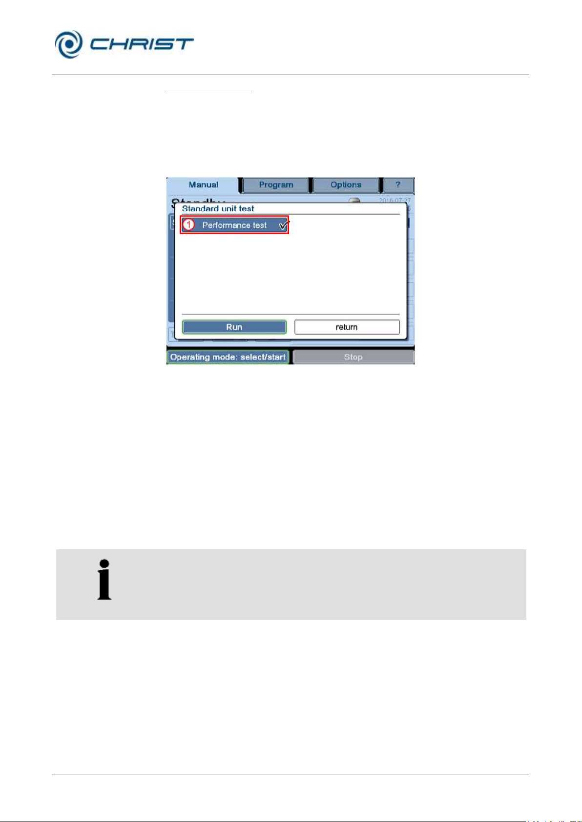
Freeze-dryer Alpha 1-4 LSCplus
Freeze-dryer Alpha 2-4 LSCplus
6 Operation
Version 01/2011, Rev. 2.3 of 03/07/2017 • sb
47 / 131
Translation of the original operating manual
NOTE
Prior to performing a test, ensure that the chamber is dry and unloaded
and that the ice condenser is defrosted.
Standard unit test
Apart from the process phases of the freeze-drying process ("Freezing",
"Warm-up", "Main drying", and "Final drying") and the operating mode
"Defrosting", the button "Unit Test" is also available. This button opens a
selection of a test with fixed parameters. After consultation with the
manufacturer, this test can be performed in order to check the functionality
and processes of the freeze-dryer.
Fig. 32: Dialog box "Standard unit test"
Performance test (1)
The performance test is used to determine the following performance
parameters:
• vacuum decrease rate
• final vacuum
• minimum ice condenser temperature
• shelf cooling rate
• minimum shelf temperature
• shelf heating rate
Procedure:
• In the main window "Manual", select the button "Operating mode:
select/start" – "Standard unit test".
• Select "Performance test" and start the test via the "Run" button.
The test will be performed. The parameters will be measured at defined
points of time, evaluated, and displayed in a dialog box in the form of a
table. The result will be indicated by way of a dialog box.
If the freeze-dryer is equipped with the LPCplus SCADA software, the
results will be documented in the event list.
Page 48

Freeze-dryer Alpha 1-4 LSCplus
Freeze-dryer Alpha 2-4 LSCplus
6 Operation
48 / 131
Version 01/2011, Rev. 2.3 of 03/07/2017 • sb
Translation of the original operating manual
Evaluation
Ice condenser temperature after 2 h
Evacuation rate
1,000 mbar … 1 mbar
xxx min
1,000 mbar … 0.1 mbar
xxx min
1,000 mbar … 0.01 mbar
xxx min
Final vacuum after 2 h
xxx mbar
Evaluation:
Please contact the Martin Christ Gefriertrocknungsanlagen GmbH for an
assessment of the results..
Button "Stop" (9)
Pressing this button stops the current process. The system switches to the
standby status.
Page 49
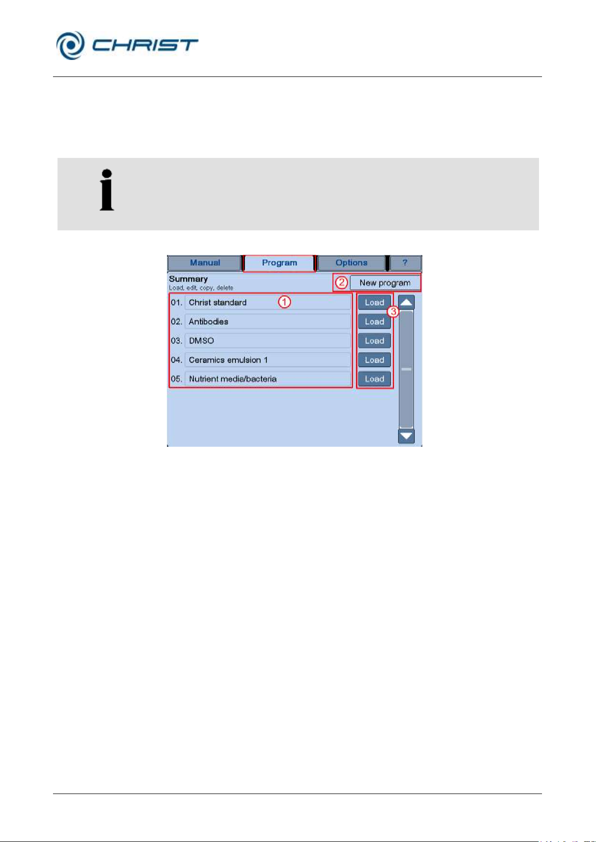
Freeze-dryer Alpha 1-4 LSCplus
Freeze-dryer Alpha 2-4 LSCplus
6 Operation
Version 01/2011, Rev. 2.3 of 03/07/2017 • sb
49 / 131
Translation of the original operating manual
NOTE
The PGMplus programmer module is an option that is not included as
standard (see chapter 6.5.3 - "Option: freeze-drying with the PGMplus
programmer module"). If the programmer module is not enabled, programs
can only be created and edited for demonstration purposes.
The execution of a program, however, is not possible!
1 Program list
2 Button "New
program"
3 Buttons "Load"
6.5.1.2 Main window "Program"
In the main window "Program", pre-programmed freeze-drying processes
can be loaded and edited and new programs can be created with the
PGMplus programmer module. For this function, the PGMplus programmer
module must be available.
Fig. 33: Overview of the main window "Program"
Program list (1)
After the selection of the main window "Program", an overview of the
programs that have already been saved will be displayed. Pressing the
button "Load" (3) behind the program name calls up the program data.
Programs can be loaded, edited, copied, or deleted (see chapter 6.5.3 "Option: freeze-drying with the PGMplus programmer module").
Dialog box "New program" (2)
In this dialog box, new programs can be created either based on an already
existing program or completely from scratch (see chapter 6.5.3.1 "Creating a program").
Page 50
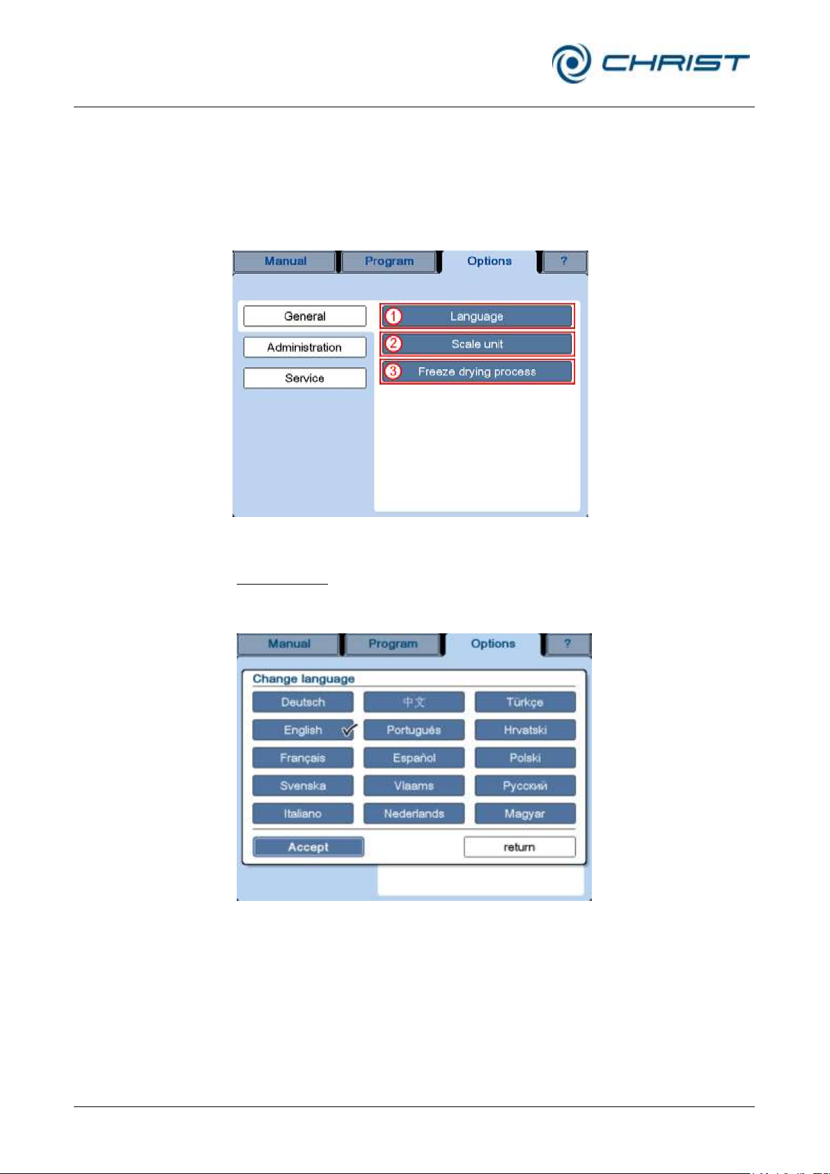
Freeze-dryer Alpha 1-4 LSCplus
Freeze-dryer Alpha 2-4 LSCplus
6 Operation
50 / 131
Version 01/2011, Rev. 2.3 of 03/07/2017 • sb
Translation of the original operating manual
“General” options:
1 "Language"
2 "Scale unit"
3 "Freeze-drying
process "
6.5.1.3 Main window "Options "
The main window "Options" is used to perform fundamental basic settings
of the control system in order to adapt it perfectly to the respective area of
application of the freeze-dryer.
General
Fig. 34: Overview of the main window "Options/General"
Language (1)
The control system can be used in several languages which can be
selected via the dialog box.
Fig. 35: Dialog box "Change language"
Page 51
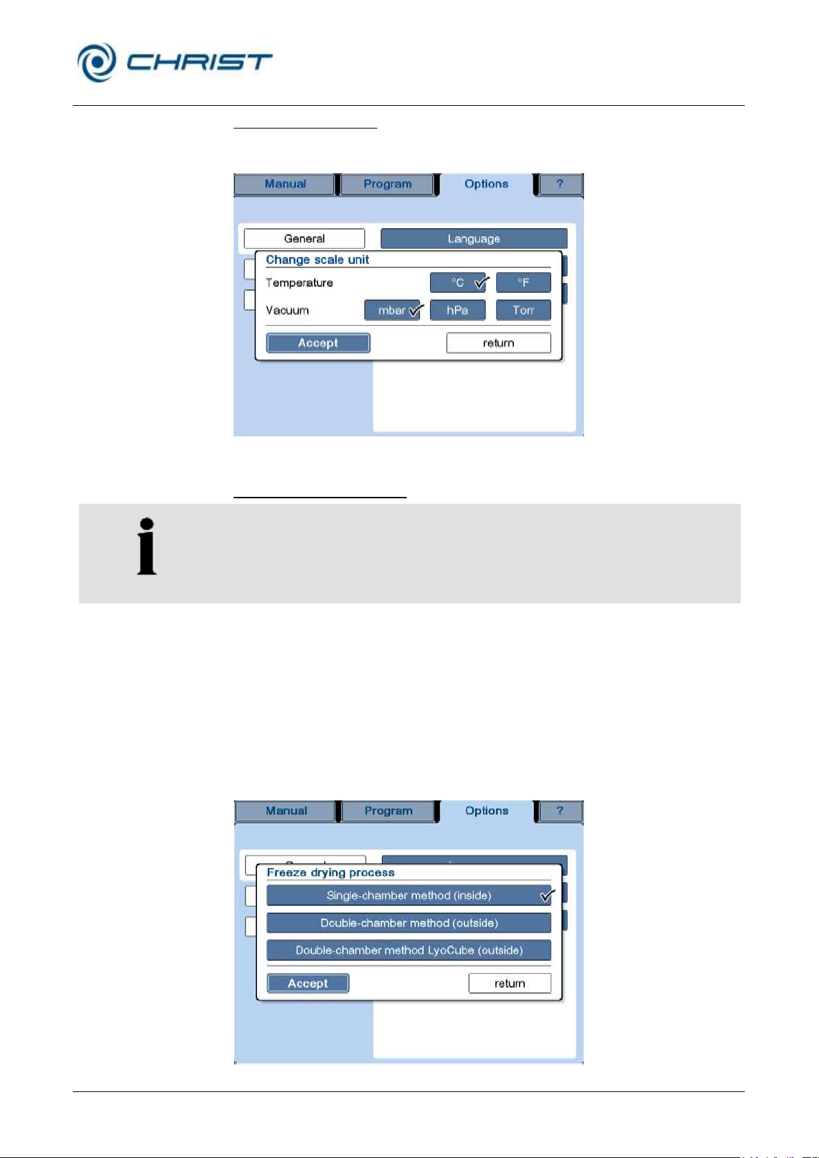
Freeze-dryer Alpha 1-4 LSCplus
Freeze-dryer Alpha 2-4 LSCplus
6 Operation
Version 01/2011, Rev. 2.3 of 03/07/2017 • sb
51 / 131
Translation of the original operating manual
NOTE
This function depends on the unit type and is not available for all types of
freeze-dryers.
Change scale unit (2)
This dialog box is used to change the unit of measurement for the
temperature and vacuum.
Fig. 36: Dialog box "Change scale unit"
Freeze-drying process (3)
Prior to the start of the process, the correct process must be selected. The
following processes are available:
• Single-chamber method (inside): drying inside the ice condenser
chamber
• Double-chamber method (outside): drying outside the ice condenser
chamber
• Double chamber method LyoCube (outside): drying outside the ice
condenser chamber, but with the CHRIST LyoCube (a rectangular
drying chamber that can be loaded from the front)
Fig. 37: Dialog box "Freeze-drying processes"
Page 52
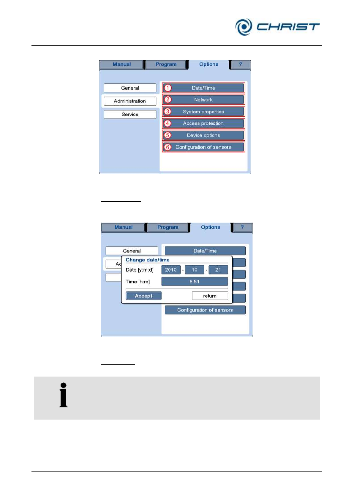
Freeze-dryer Alpha 1-4 LSCplus
Freeze-dryer Alpha 2-4 LSCplus
6 Operation
52 / 131
Version 01/2011, Rev. 2.3 of 03/07/2017 • sb
Translation of the original operating manual
“Administration”
options:
1 "Date/Time"
2 "Network"
3 "System properties"
4 "Access protection"
5 "Device options"
6 "Configuration of
sensors"
NOTE
The modifications will not become effective until after a restart of the unit.
Administration
Abb. 38: Dialogfenster "Optionen" / Verwaltung
Date/Time (1)
The LSC
clock. After a failure of the buffer battery, the date and time must be reset.
control system is equipped with an integrated, battery-buffered
plus
Fig. 39: Dialog box “Change date/time
Network (2)
This dialog box is used to change various system settings.
Page 53
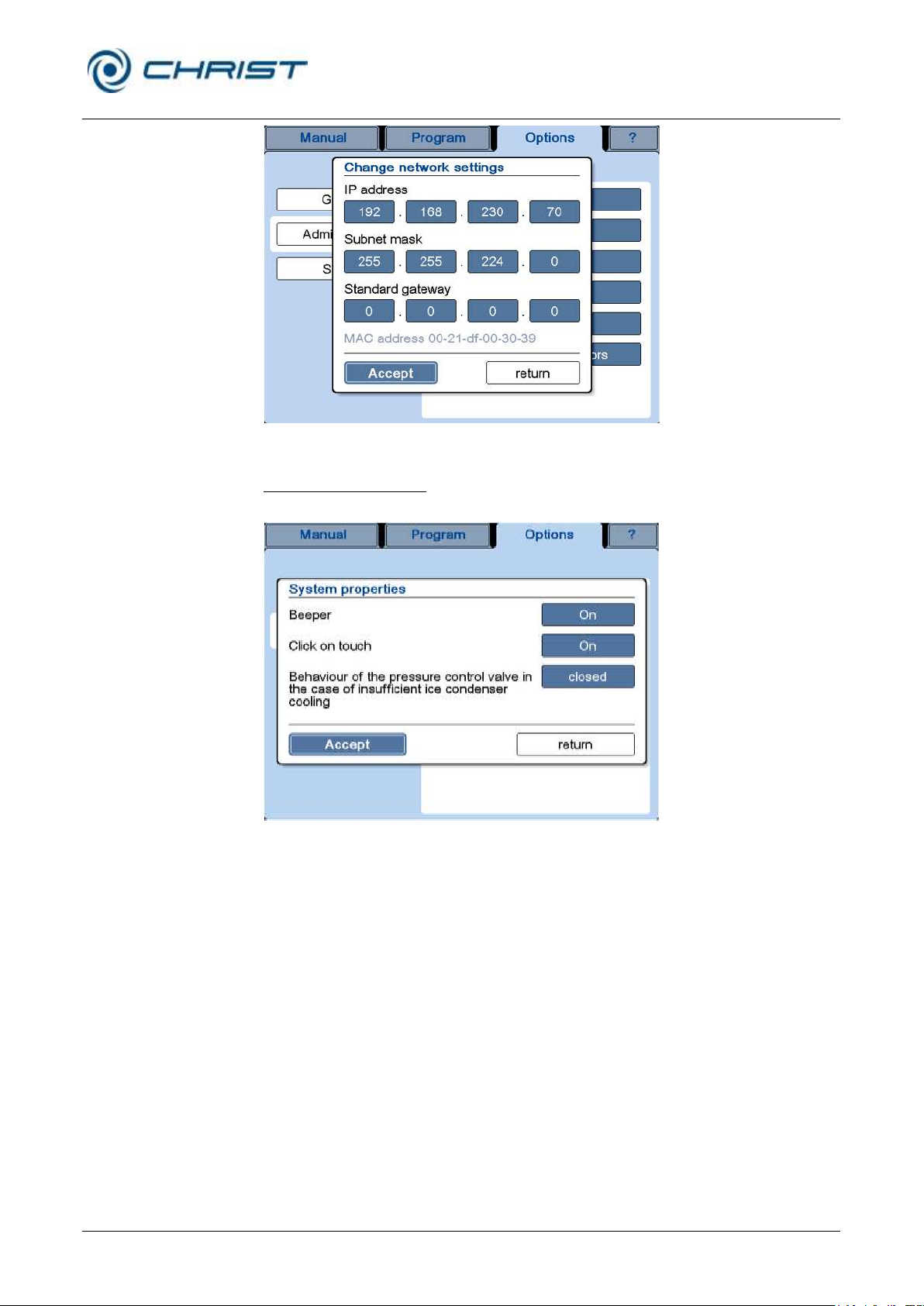
Freeze-dryer Alpha 1-4 LSCplus
Freeze-dryer Alpha 2-4 LSCplus
6 Operation
Version 01/2011, Rev. 2.3 of 03/07/2017 • sb
53 / 131
Translation of the original operating manual
Fig. 40: Dialog box "Network"
System properties (3)
This dialog box is used to change various system settings.
Fig. 41: Dialog box "System properties"
Beeper: The beeper sounds in the event of a malfunction, for example.
• If the setting is "On", the beeper sounds every few seconds until the
• If the setting is "Silent", the beeper sounds once when the malfunction
• If the setting is "Off", the beeper will not sound at all.
Click on touch: If this function is active, a clicking sound can be heard
whenever the system registers that a button has been touched.
Behaviour of the pressure control valve in the case of insufficient ice
condenser cooling: If this function is active (button "closed"), the pressure
control valve will close at an ice condenser temperature of
≥ -20°C during the drying process in order to avoid damage to the vacuum
pump caused by the withdrawal of condensable gases. A corresponding
error message will be displayed. Pressing the button again deactivates the
function (button "controlled").
user acknowledges the message.
occurs.
Page 54
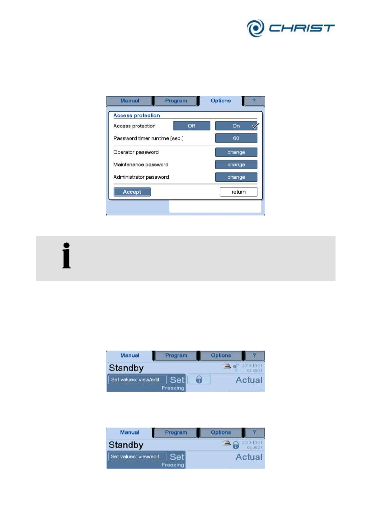
Freeze-dryer Alpha 1-4 LSCplus
Freeze-dryer Alpha 2-4 LSCplus
6 Operation
54 / 131
Version 01/2011, Rev. 2.3 of 03/07/2017 • sb
Translation of the original operating manual
NOTE
The other buttons cannot be activated unless the access protection is
active.
Access protection (4)
In this dialog box, the access rights can be managed on several levels and
they can be protected with a password.
In the factory setting with an activated access protection, data can be
viewed but not edited.
Fig. 42: Dialog box "Access protection"
Password timer runtime: In order to prevent unauthorised access, the
system will automatically switch back to the default setting after a predefined period of time.
In this case, there is a small lock symbol in the status line and below this
symbol the remaining time until the lock will be active is counted down. At
the same time a button with a big lock symbol will be displayed in the actual
values field.
Fig. 43: Countdown of the password timer and the button with the lock symbol
• The button with the lock symbol blocks the access immediately and the
system switches to the default setting.
Fig. 44: Access blocked, the data cannot be edited
Page 55
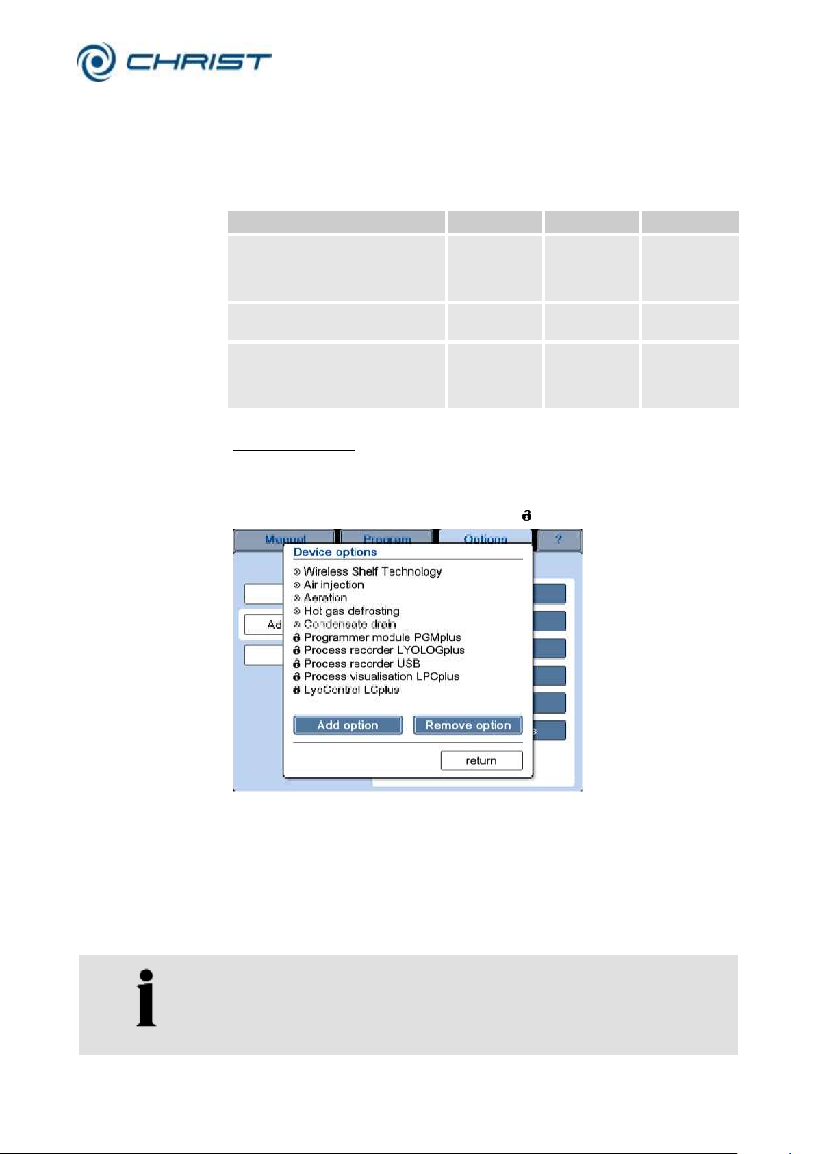
Freeze-dryer Alpha 1-4 LSCplus
Freeze-dryer Alpha 2-4 LSCplus
6 Operation
Version 01/2011, Rev. 2.3 of 03/07/2017 • sb
55 / 131
Translation of the original operating manual
Action
Operator
Maintenance
Administrator
Editing of the data of the current
process run (e.g. selection of the
operating mode, changing of set
values)
Editing of maintenance functions (e.g.
oil change of the vacuum pump)
--
Editing of the default settings (e.g.
editing of the access protection,
creating and editing of programs,
editing of system settings)
--
--
NOTE
The modifications will not become effective until after a restart of the unit.
Operator/maintenance/administrator password: For each of these access
levels, certain editing rights have been defined. They can be enabled with
the corresponding password.
The rights of the various access levels are detailed in the following table.
Device options (5)
This dialog box lists all of the device options that are available for the unit in
question. A list of all the possible options can be found at chapter 6.6 "Optional extensions". Options that require a series-number-specific
release code are marked with the symbol (" ").
Fig. 45: Dialog box “Device options” (example)
If the freeze-dryer is to be extended by an option, this option must be
enabled via this dialog box.
• Press the button "Add option". An input window opens.
• Enter the six-digit Christ activation code that was supplied for this
option. Note that the keys are case sensitive.
Options can be removed in the same way.
Page 56
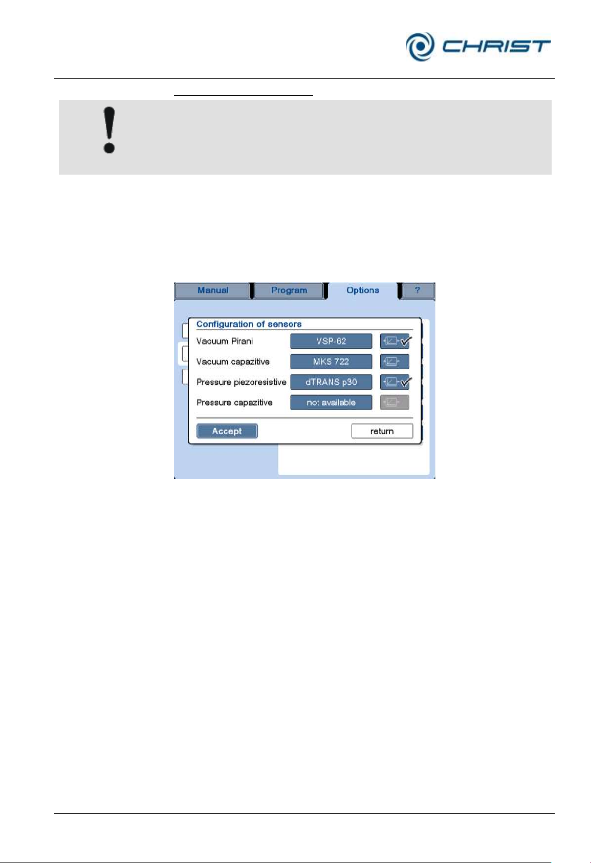
Freeze-dryer Alpha 1-4 LSCplus
Freeze-dryer Alpha 2-4 LSCplus
6 Operation
56 / 131
Version 01/2011, Rev. 2.3 of 03/07/2017 • sb
Translation of the original operating manual
CAUTION
The sensor configurations depend on the equipment version of the unit. If
the configuration is incorrect, the correct operation of the unit cannot be
guaranteed.
Configuration of sensors (6)
This dialog box is used to configure the existing vacuum and pressure
sensors. For the vacuum as well as pressure, there are two different
measuring methods, and for each of these methods, different sensors can
be selected.
• In order to change the sensor, press the button with the sensor name.
The possible models will be displayed one after the other.
Fig. 46: Dialog box "Configuration of sensors"
The buttons on the right-hand side of the sensors show a control symbol.
The tick marks on the buttons indicate the control sensors, i.e. the sensors
that are decisive for the vacuum inside the unit. If there is a second sensor,
the data of this sensor are simply used for comparison.
Page 57
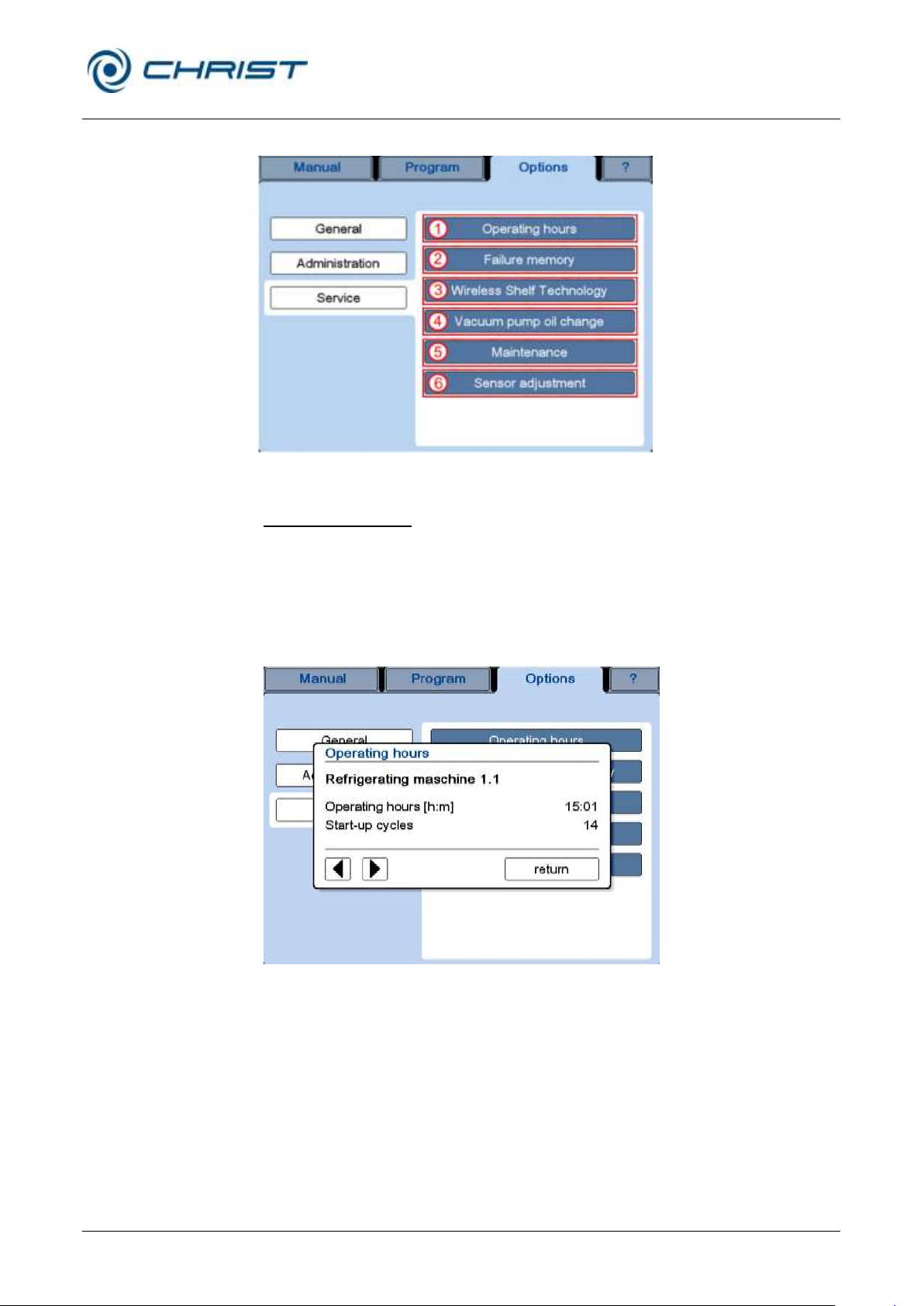
Freeze-dryer Alpha 1-4 LSCplus
Freeze-dryer Alpha 2-4 LSCplus
6 Operation
Version 01/2011, Rev. 2.3 of 03/07/2017 • sb
57 / 131
Translation of the original operating manual
“Service” options:
1 "Operating hours"
2 "Failure memory"
3 "Wireless shelf
technology"
4 "Vacuum pump oil
change"
5 "Maintenance"
6 "Sensor adjustment"
Service
Fig. 47: Dialog box "Service" (varies depending on the type of system)
Operating hours (1)
This dialog box is used to call up the number of operating hours of the
various components of the freeze-dryer, e.g. the refrigeration unit, vacuum
pump, or pressure control valve. In addition to the name, the reference
designator is also displayed.
These data are provided for the purpose of information only. They cannot
be edited.
Fig. 48: Dialog box "Operating hours" (here: refrigeration unit 1.1)
Page 58
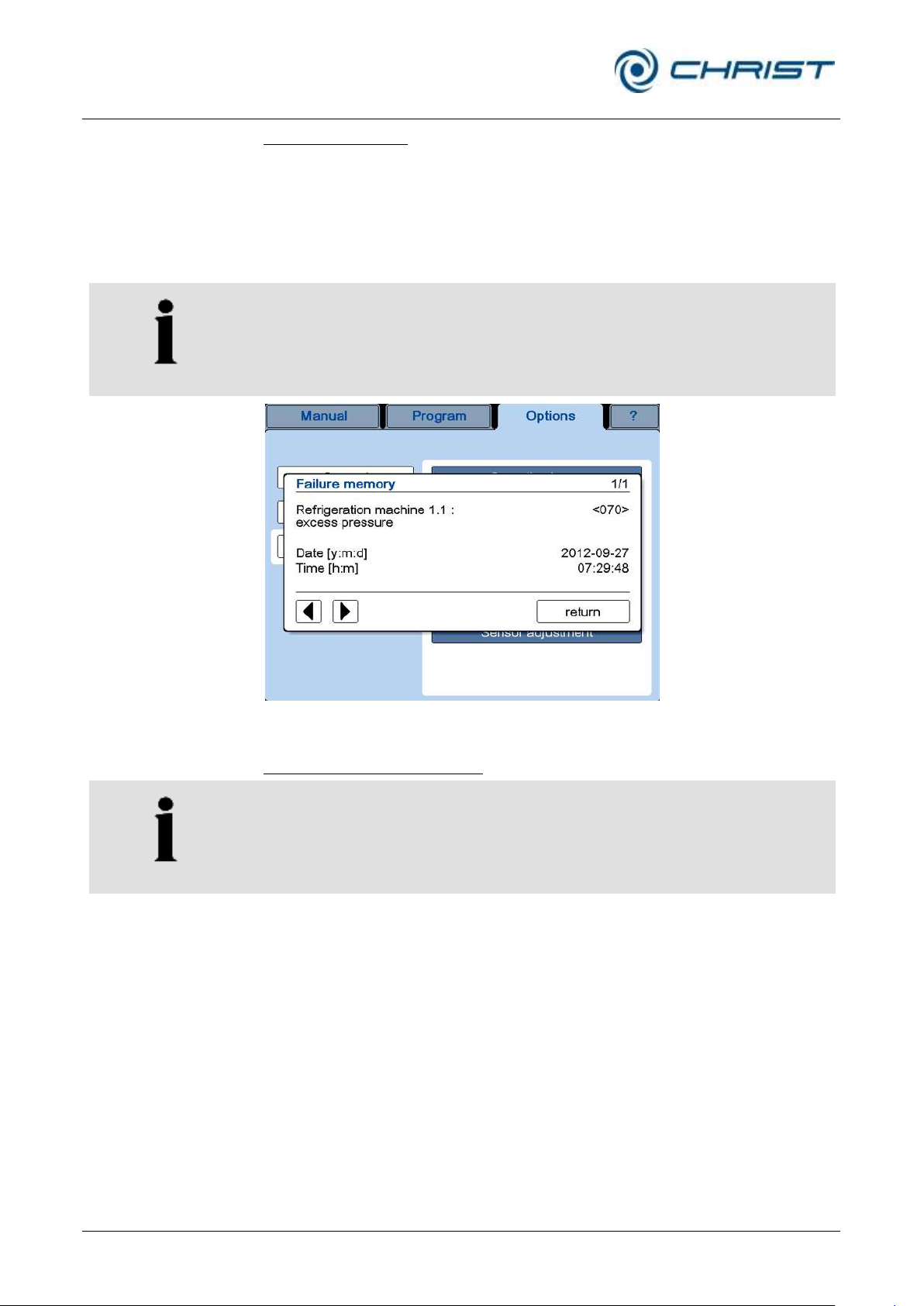
Freeze-dryer Alpha 1-4 LSCplus
Freeze-dryer Alpha 2-4 LSCplus
6 Operation
58 / 131
Version 01/2011, Rev. 2.3 of 03/07/2017 • sb
Translation of the original operating manual
NOTE
Always indicate the error code in the event of enquiries or service
requests!
NOTE
This function depends on the unit type and is not available for all types of
freeze-dryers.
Failure memory (2)
The failure memory stores the most recent messages of the process and
equipment information system. These messages can be viewed in this
dialog box. The failure memory includes the last 32 messages. If this
number is exceeded, the oldest message will be overwritten.
Use the arrow keys to call up the individual messages.
The error message text is always followed by an error code.
Fig. 49: Dialog box "Failure memory"
Wireless shelf technology (3)
The wireless shelf technology enables the wireless control and
monitoring of the shelf temperature. For this purpose, an address must be
assigned to the WST modules of the shelves. The number of available
addresses is fixed depending on the unit variant.
Page 59
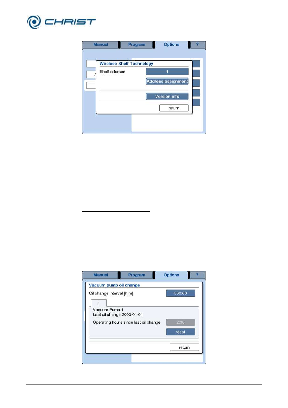
Freeze-dryer Alpha 1-4 LSCplus
Freeze-dryer Alpha 2-4 LSCplus
6 Operation
Version 01/2011, Rev. 2.3 of 03/07/2017 • sb
59 / 131
Translation of the original operating manual
Fig. 50: Wireless shelf technology – assignment of shelf addresses
• In order to assign an address, open the dialog box "Wireless Shelf
Technology".
• Ensure that only the WST module to which an address is to be assigned
is connected. If several modules are connected, they will all receive the
same address, resulting in a communication conflict.
• Press the button "Address assignment", process the prompt, and
confirm the address assignment.
Vacuum pump oil change (4)
The system monitors the oil change interval of the vacuum pump.
The interval can be adapted to the vacuum pump model and utilisation.
When the end of an oil change interval is reached, a corresponding
message will be displayed.
• Acknowledge the message.
• Change the oil of the vacuum pump.
• Reset the operating hour counter in the dialog box “Vacuum pump oil
change” by pressing the “reset” button.
Fig. 51: Dialog box "Vacuum pump oil change"
Page 60
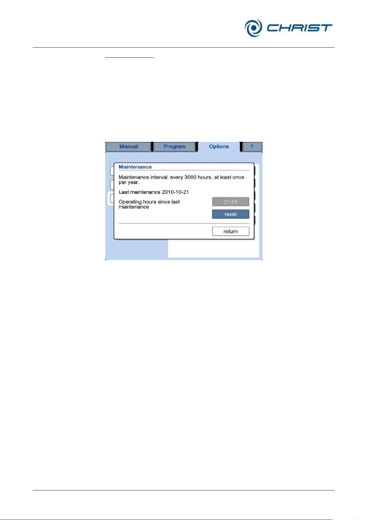
Freeze-dryer Alpha 1-4 LSCplus
Freeze-dryer Alpha 2-4 LSCplus
6 Operation
60 / 131
Version 01/2011, Rev. 2.3 of 03/07/2017 • sb
Translation of the original operating manual
Maintenance (5)
The maintenance interval of the unit is fixed at 3,000 operating hours or at
least one maintenance per year.
When the end of a maintenance interval is reached, a corresponding
message will be displayed.
• Acknowledge the message.
• Make an appointment for the maintenance of your freeze-dryer (see
section 8 "Maintenance and service").
• After the maintenance, our service engineer will reset the operating
hour counter in the dialog box "Maintenance".
Fig. 52: Dialog box "Maintenance"
Page 61
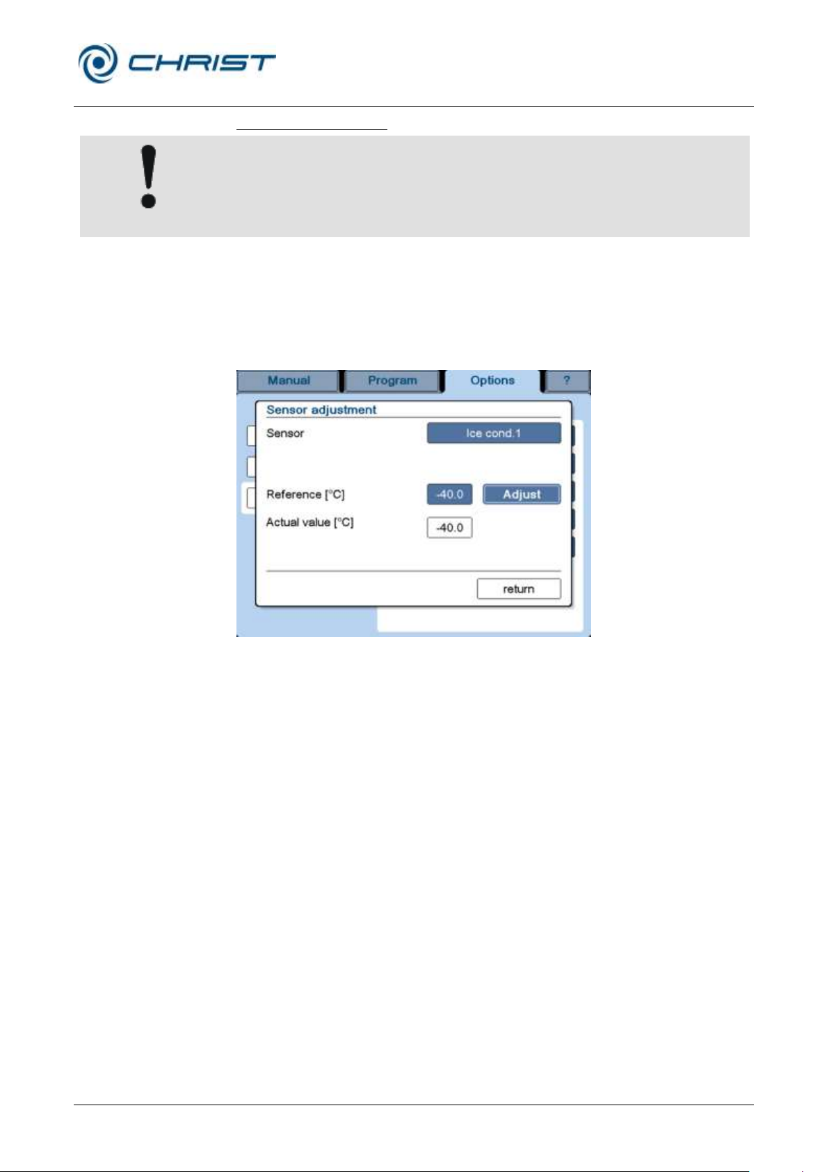
Freeze-dryer Alpha 1-4 LSCplus
Freeze-dryer Alpha 2-4 LSCplus
6 Operation
Version 01/2011, Rev. 2.3 of 03/07/2017 • sb
61 / 131
Translation of the original operating manual
CAUTION
Misadjusted sensors will lead to incorrect measurement values, which in
turn will have a negative effect on the process control.
Sensor adjustment (6)
In this dialog box, the sensors are adjusted in terms of a predefined
reference value.
• Press the button in order to select the sensor. A selection menu will be
displayed.
• Enter a reference value and press the button "Adjust".
Fig. 53: Dialog box "Sensor adjustment"
Page 62
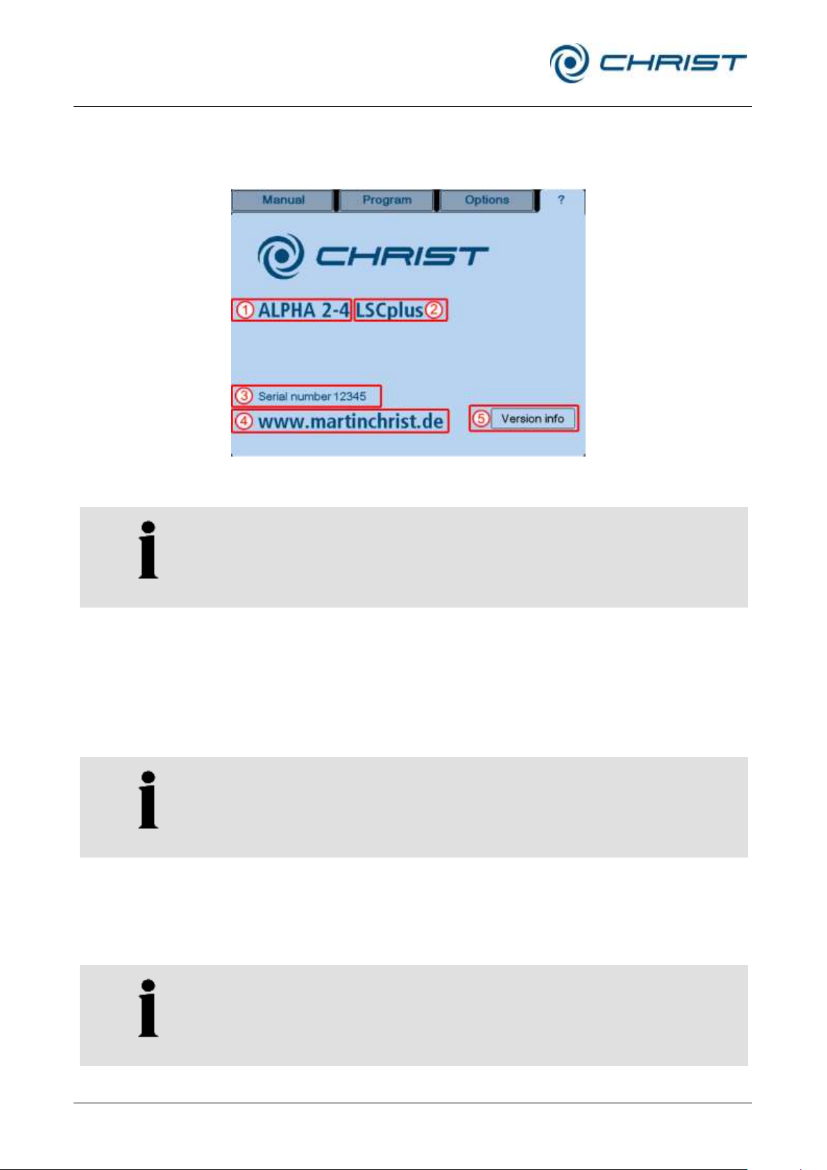
Freeze-dryer Alpha 1-4 LSCplus
Freeze-dryer Alpha 2-4 LSCplus
6 Operation
62 / 131
Version 01/2011, Rev. 2.3 of 03/07/2017 • sb
Translation of the original operating manual
1 Freeze-dryer type
2 Control system type
3 Serial number
4 Manufacturer contact
data
5 Details concerning the
software version
NOTE
In the event of enquiries at the manufacturer, please state the number that
is stated here.
NOTE
Prior to any freeze-drying process, the correct method must be selected
(chapter 6.5.1.3 - "Main window "Options "", section “Freeze drying
process (3)").
NOTE
If the freeze-drying process is to be started directly with the "main drying"
(sublimation) phase, the vacuum pump must be warmed up approximately
15 minutes prior to the process start. Failure to do so will result in a
corresponding warning message when the process starts.
6.5.1.4 Main window "?"
This main window includes the most important information concerning your
freeze-dryer:
6.5.2 Manual freeze-drying
Fig. 54: Freeze-dryer system information, here for Alpha 2-4 LSCplus
In the manual mode, the user switches manually from one freeze-drying
phase to the next. The manual mode is activated by calling up the main
window "Manual".
The set values for the individual process phases (freezing, warm-up, main
drying, and final drying) are defined prior to the start of the process. Then,
the freeze-drying process can be started via the dialog box "Operating
mode: select/start".
Page 63
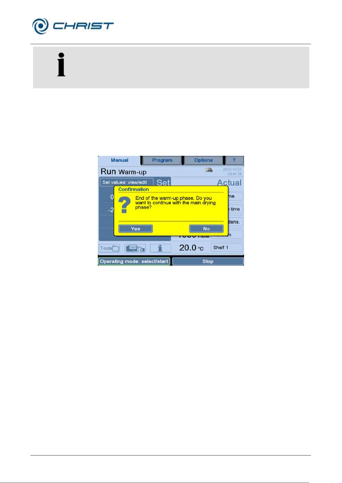
Freeze-dryer Alpha 1-4 LSCplus
Freeze-dryer Alpha 2-4 LSCplus
6 Operation
Version 01/2011, Rev. 2.3 of 03/07/2017 • sb
63 / 131
Translation of the original operating manual
NOTE
If in one section the value "∞" (infinite) is selected for a process phase, the
next phase must be started manually via the button "Operating mode:
select/start".
In the manual mode, the set values of the active phase can be changed
during the process run. In this case, the control system adapts the unit to
the new set values as quickly as possible.
After the completion of a phase, the system switches to the next phase
without switching the unit to standby. The transition from "freezing" to
"warm-up" takes place automatically. After the completion of the warm-up
phase, this dialog box will be displayed:
Fig. 55: Dialog box after the completion of the warm-up phase
The unit will remain in the warm-up phase until you confirm.
The transition from "main drying" to "final drying" again takes place
automatically. After the completion of the "final drying" phase, the system
displays another enquiry with which the freeze-drying process will be
terminated. The unit remains in the "run" mode until the enquiry is
confirmed.
The process can be stopped any time by pressing the "Stop" button. In this
case, the unit will be switched to standby.
6.5.2.1 Entering set values in the manual mode
The system has stored set values for every phase, and for every value
there are pre-defined value ranges that can be determined in the various
dialog boxes by pressing the buttons "min" and "max".
In order to protect the product, a safety pressure value can be entered in
every drying section.
Page 64
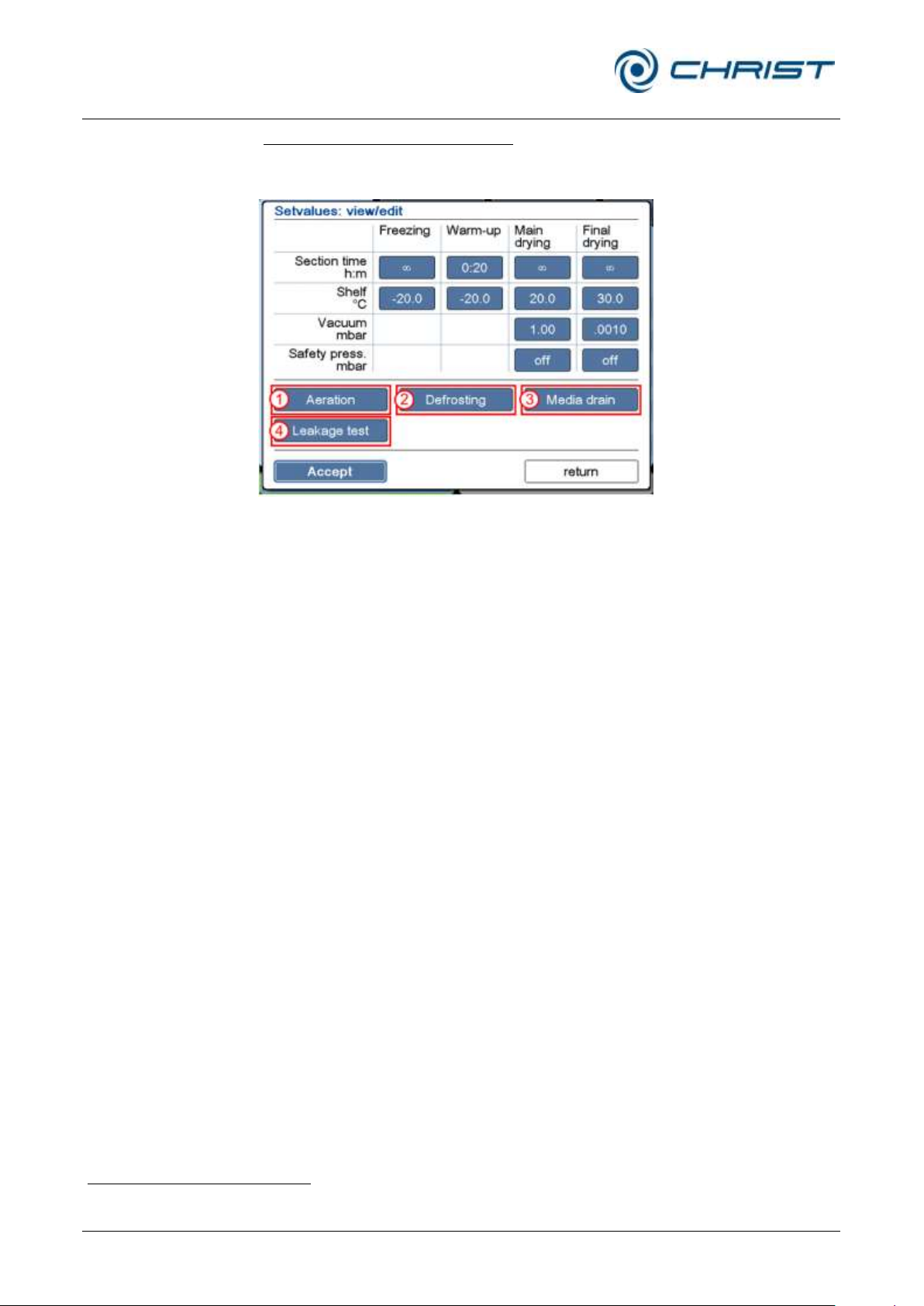
Freeze-dryer Alpha 1-4 LSCplus
Freeze-dryer Alpha 2-4 LSCplus
6 Operation
64 / 131
Version 01/2011, Rev. 2.3 of 03/07/2017 • sb
Translation of the original operating manual
1 "Aeration" button
2 "Defrosting" button
3 "Media drain" button
(special equipment)
4 "Leakage test" button
(option)
1
Viewing or editing the set values:
• Press the button "Set values: view/edit" (see chapter 6.5.1.1 - "Main
window "Manual""). The following dialog box will be displayed:
Fig. 56: Dialog box "Set values: view/edit"
Fields that are displayed in the form of buttons can be edited.
• Aeration (1)
If the freeze-dryer is equipped with an automatic aeration valve, this
button is used to define the aeration pressure.
• Defrosting (2)
This button is used to pre-define the defrosting time and temperature1.
In addition, this button is used to define whether the operating mode
“media drain” (see below) will be started automatically after the
defrosting process.
• Media drain (3)
If the freeze-dryer is equipped with an automatic media drain for
condensate water or another medium, the opening time of the drain
valve can be pre-selected in this dialog box.
• Leakage test (4)
This function is optional (see chapter 6.6 - "Optional extensions"). This
button displays the parameters that are used for the leakage test. In
addition, the test time and the chamber volume must be stated
(depending on the accessories that are used).
not for hot-water defrosting
Page 65
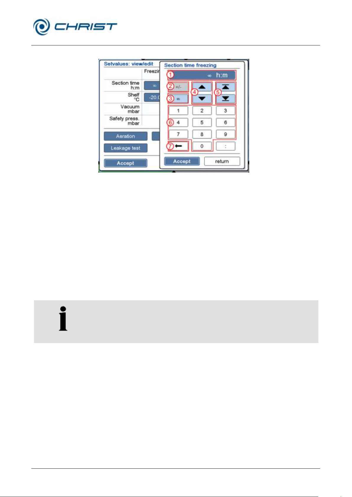
Freeze-dryer Alpha 1-4 LSCplus
Freeze-dryer Alpha 2-4 LSCplus
6 Operation
Version 01/2011, Rev. 2.3 of 03/07/2017 • sb
65 / 131
Translation of the original operating manual
1 Set value display
2 Button for changing the
sign (e.g. when entering
temperature values)
3 "" (infinite)
4 Button for editing the
value in pre-defined
steps
5 Selection of a possible
maximum or minimum
value
Input of a value via the
numerical keypad
7 Button for deleting the
displayed value
NOTE
The PGMplus programmer module is an option that is not available as
standard. If the programmer module is not enabled, programs can be
created and edited for demonstration purposes only. The execution of a
program, however, is not possible in this case!
Numerical values can be edited with the aid of a numerical keypad:
Fig. 57: Editing set values
• Confirm the new value and quit the numerical keypad by pressing the
button "Accept".
• Confirm the input and quit the dialog box via the button "Accept".
• If the dialog box is closed by the button "return", the changes will be
discarded.
6.5.3 Option: freeze-drying with the PGMplus programmer module
Unlike in the manual mode, an entire freeze-drying process can be
executed fully automatically and under reproducible conditions with the aid
of the PGMplus programmer module.
Freeze-drying programs are divided into sections (1). Every section in the
program has certain set values (2). A program must include a minimum of
two sections, and the maximum number of possible sections is 64.
32 program storage locations are available.
In every program, the system always displays four consecutive sections in
order to show their connection.
Page 66
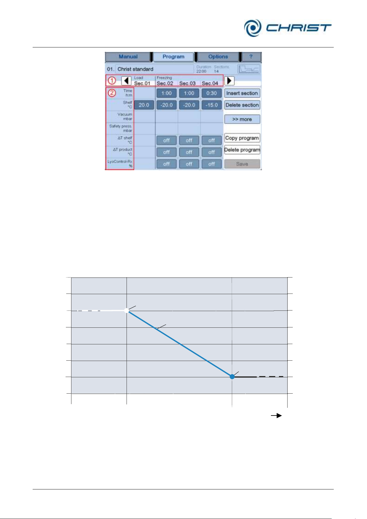
Freeze-dryer Alpha 1-4 LSCplus
Freeze-dryer Alpha 2-4 LSCplus
6 Operation
66 / 131
Version 01/2011, Rev. 2.3 of 03/07/2017 • sb
Translation of the original operating manual
T/°C
t/h
1000
100
10
1
0.1
0.01
0.001
0.0001
+40
+30
+20
+10
0
-10
-20
-30
Pressure/mbar
Set value of the previous section
Course of the shelf temperature
control set value
Set value of the
current section
Previous
section
Current
section
Following
section
Fig. 58: Representation of a freeze-drying program
Program sections
When the programmer module executes a freeze-drying process, it
executes the various sections that were created one after the other until the
last section is completed.
Within the various sections, the system calculates linear ramps for the
temperature and vacuum. These ramps start with the set value of the
previous section and end with the set value of the current section.
As a result, there is not abrupt change of the set value from section to
section, but a steady adaptation.
Fig. 59: Graphical representation of the course of the control set value
In order to protect the product, a safety pressure value can be entered in
every drying section.
Page 67

Freeze-dryer Alpha 1-4 LSCplus
Freeze-dryer Alpha 2-4 LSCplus
6 Operation
Version 01/2011, Rev. 2.3 of 03/07/2017 • sb
67 / 131
Translation of the original operating manual
Conditions for switching to the next section
For all of the program sections to be executed automatically, certain
switching conditions must be fulfilled at the end of each section. If these
conditions are not fulfilled, e.g. due to incorrect set values, a corresponding
process message will be displayed and the section will be extended.
Ice condenser temperature: This value is checked only when the system
switches from freezing (loading) to drying. The ice condenser temperature
must be -40°C.
Vacuum: This value is checked only during the drying phase. The actual
vacuum can differ from the set value by 20% maximum. In the case of a set
value of 0.001 mbar (final vacuum), there will be no check. In order to reach
the vacuum as quickly as possible, a section time of 1 minute can be
preselected. Since this is not possible in practice, a process message will
be issued for the first time after 15 minutes in this case.
T shelf: This value defines the permissible deviation of the shelf
temperature from the set value. At the end of the section, the actual
temperature of the shelves (in the case of WST shelf 1) will be compared to
the set value. If the shelf temperature is beyond the permissible range, the
section will be extended until the deviation is within the permissible range.
T product: This value defines the permissible deviation of the product
temperature (measured by product sensor 1) from the set value. During the
freezing phase, the product temperature may exceed the set value by the
defined value. In the drying phase, the system will provide a signal to the
user if the actual value lies below the set value by more than the
permissible deviation.
LyoControl-Rx (option with LyoControl LCplus): The value LyoRx defines
the minimum permissible value of the LyoControl sensors (measured by the
LyoControl sensor 1) during the drying phase. If the actual value falls below
this limit, the shelf heater will be switched off in order to prevent the product
from thawing due to excessive energy input by the shelf temperature
control system. The LyoControl value is checked only during the main and
final drying phases.
p pressure increase test (option): Depending on the selected mode, the
pressure increase test can also be used as a condition for switching to the
next section (see chapter 6.5.3.1 - "Creating a program", option: pressure
increase test). In the last drying section, two pressure increase tests will be
performed and evaluated. If both values are not greater than the specified
"pressure increase" parameter, the condition for switching to the next
section is fulfilled. If this is not the case, the section will be extended. If the
actual value exceeds the set value before the preselected time has
elapsed, the test will be aborted in order to prevent the product from
thawing.
T comparative (option): This value indicates the difference between a
Pirani sensor and a capacitive vacuum sensor in per cent based on the
actual value of the capacitive vacuum sensor. When the sublimation rate
decreases, the difference decreases as well. As a result, the value is an
indicator for determining the drying end of the main draining phase. If the
set value is not reached by the end of the main drying phase, the section
will be extended.
Page 68
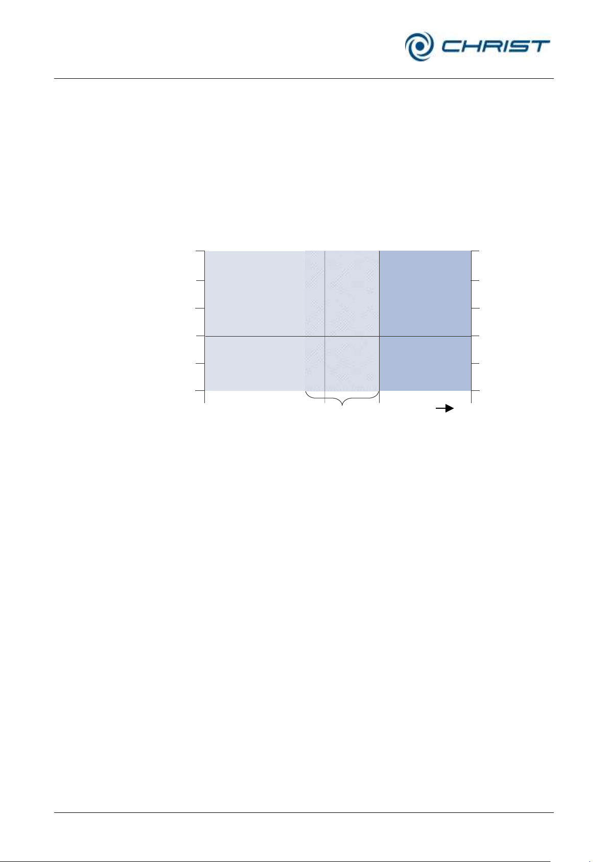
Freeze-dryer Alpha 1-4 LSCplus
Freeze-dryer Alpha 2-4 LSCplus
6 Operation
68 / 131
Version 01/2011, Rev. 2.3 of 03/07/2017 • sb
Translation of the original operating manual
T/°C
t/h
100
10
1
0.1
0.01
0.001
+30
+20
+10
0
-10
-20
Pressure/mbar
Section
“freezing”
First
section
“drying”
Warm-up phase
of the vacuum pump
Last
section
“freezing”
Vacuum pump warm-up
Apart from the execution of the various sections, the PGMplus programmer
module also controls other tasks that need to be performed during the
process run, e.g. the automatic activation of the vacuum pump.
If the pressure control valve is closed, the PGMplus programmer module
shifts the warm-up phase of the vacuum pump to the freezing phase so that
it is before the first drying section. Since the pressure control valve remains
closed during the warm-up of the vacuum pump, neither the freezing phase
nor the pressure inside the drying chamber will be affected.
The duration of the warm-up phase can be specified separately for every
program (see chapter 6.5.3.1 - "Creating a program").
Fig. 60: The warm-up phase of the vacuum pump is shifted to the freezing phase directly
before the first drying section
Page 69
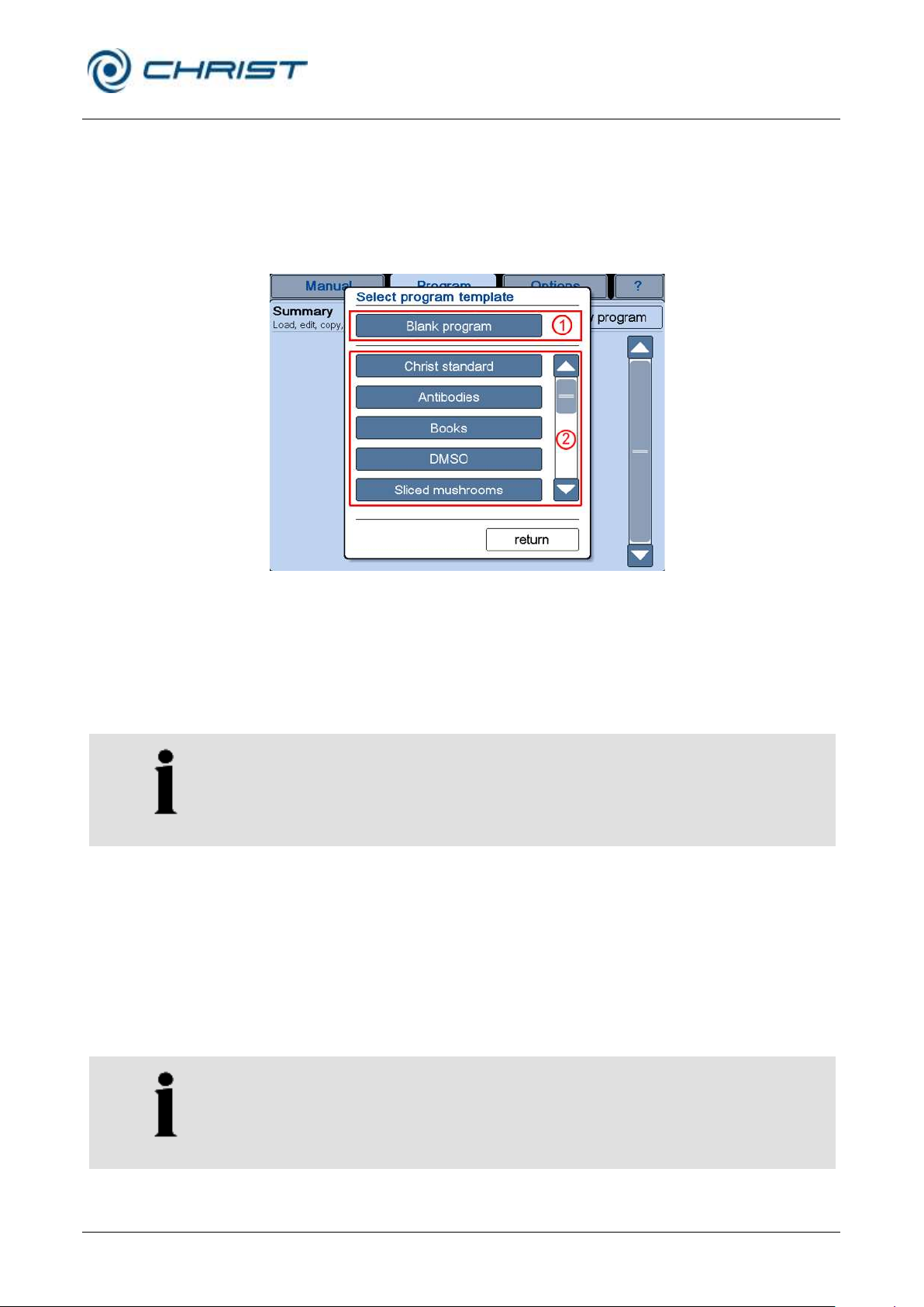
Freeze-dryer Alpha 1-4 LSCplus
Freeze-dryer Alpha 2-4 LSCplus
6 Operation
Version 01/2011, Rev. 2.3 of 03/07/2017 • sb
69 / 131
Translation of the original operating manual
1 Button for creating a
blank program
2 Scroll bar for
selecting a program
template
NOTE
If the product is frozen outside the freeze-dryer (double-chamber method),
the shelf temperature must be adapted accordingly in section 1.
NOTE
During the creation of a program, the order of the individual freeze-drying
phases must be maintained. This means that it is not possible to insert a
freezing section after a main drying section.
6.5.3.1 Creating a program
To create a new program:
• Press the button "New program" in the main window "Program". The
dialog box that is displayed offers various different program templates.
The scroll bar on the right-hand side can be used to scroll through the
list.
Fig. 61: Dialog box "Select program template"
Creating a blank program (1)
This button is used to call up a blank program template. Only section 1 is
pre-defined as the loading section. In this phase, the start conditions of the
programs are defined. The room temperature (20°C) is the standard
default.
For all the other sections, the set values must be defined (see figure
below):
• Press the button “Insert section” (4) and select the position of the
section as well as the freeze-drying phase. The section will be inserted
at the defined position.
• Adapt the parameters of the inserted section. All of the values are not
available in all of the freeze-drying phases.
• Insert and edit the next section.
Page 70
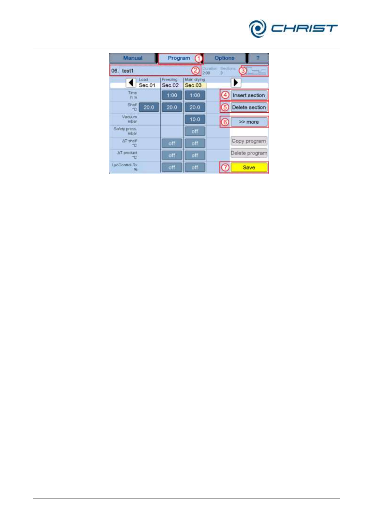
Freeze-dryer Alpha 1-4 LSCplus
Freeze-dryer Alpha 2-4 LSCplus
6 Operation
70 / 131
Version 01/2011, Rev. 2.3 of 03/07/2017 • sb
Translation of the original operating manual
“Program” buttons:
1 "Program"
2 "Program name"
3 "Show diagram "
4 "Insert section "
5 "Delete section "
6 Button for calling up
more functions and
set values
7 "Save"
Fig. 62: Editing a blank program template
• The button “Delete section” (5) can be used to delete sections.
• The button ">>more" (6) can be used to enter more functions and set
values in a program-related manner, depending on the type of freezedryer (see the sections below).
• Proceed in this manner in order to create an entire program according
to your specific needs.
• Pressing the button “Diagram” (3) displays the program in the form of a
diagram.
• Pressing the button “Program name” (2) calls up an input field in which
the name of the program can be changed.
• The button “Save” (7) can be used in between or at the end of the
program creation in order to save the program.
• The button “Program” (1) calls up the main window. The system will ask
the user whether the program shall be saved if this has not been done
yet.
The program will be automatically assigned to the first free program storage
location. The creation of the program is now complete and it can be loaded.
Page 71
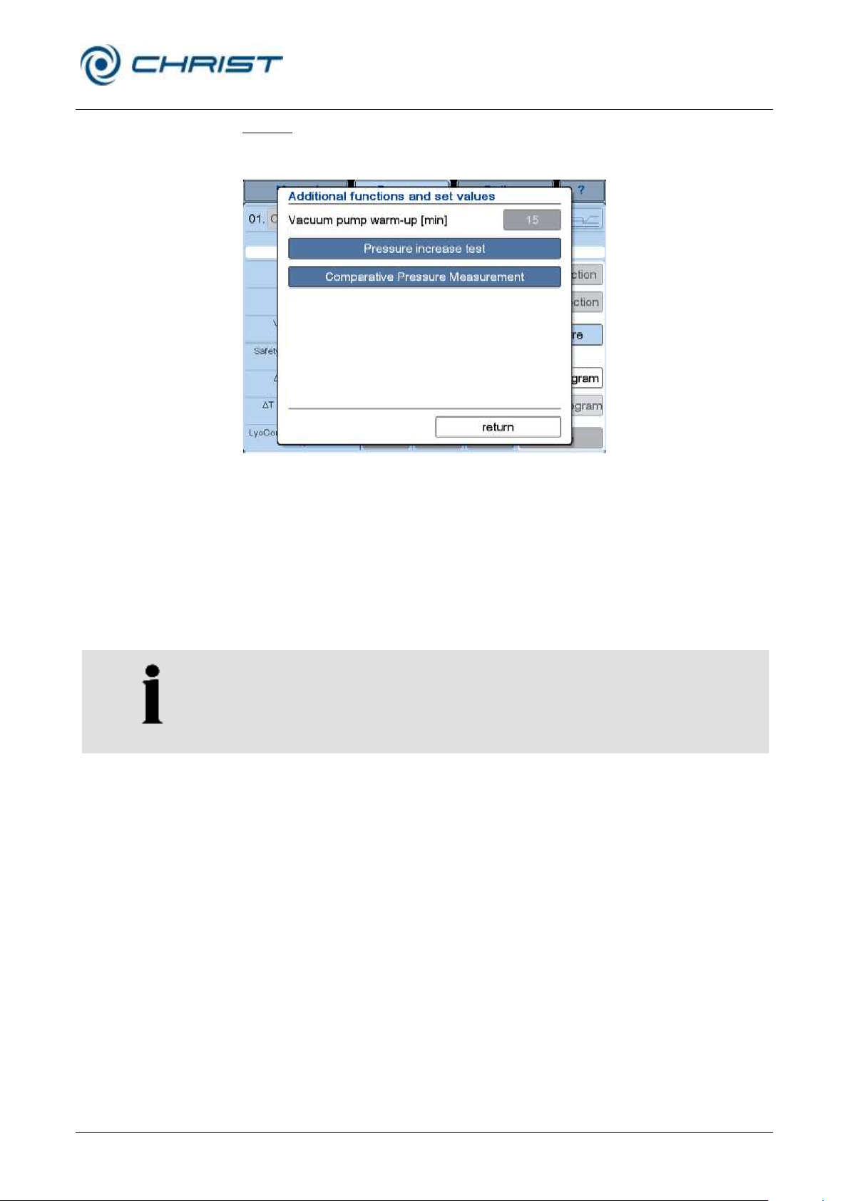
Freeze-dryer Alpha 1-4 LSCplus
Freeze-dryer Alpha 2-4 LSCplus
6 Operation
Version 01/2011, Rev. 2.3 of 03/07/2017 • sb
71 / 131
Translation of the original operating manual
NOTE
The indication of the measurement value "dp Test" can be configured in
chapter 6.5.1.1 - "Main window "Manual"" under "Actual values of the
current process" in the dialog box "Select actual value".
Button ">>more"
The button ">>more" can be used to enter more functions and set values in
a program-related manner.
Fig. 63: Selection of program-related functions and set values
Vacuum pump warm-up
See chapter 6.6 - "Optional extensions"
Option: Pressure increase test (only with the double chamber method)
(see chapter 6.6 - "Optional extensions")
The pressure increase test can only be performed when the freeze-dryer
is equipped with an intermediate valve.
In contrast to the pressure increase test in the manual mode, repeated
pressing of the button in the program mode enables the selection of
different variants.
• Periodic pressure increase test:
The test will be performed periodically during the entire main or final
drying phase. The parameters "Duration test" and "Time between tests"
apply. The maximum pressure increase is limited to 100%, referring to
the actual value at the beginning of the measurement. If the value is
exceeded, the pressure increase test will be aborted in order to prevent
the product from thawing.
• Progress condition:
In the last main drying or final drying section, two pressure increase
tests will be performed and evaluated. The start point will be calculated
automatically by the control system. The parameters "Duration test" and
"Time between tests" apply.
If both tests have been passed, the drying process will be considered
complete at the current conditions. Thus the progress condition for
switching to the next section is fulfilled and the next section will be
initiated.
Page 72
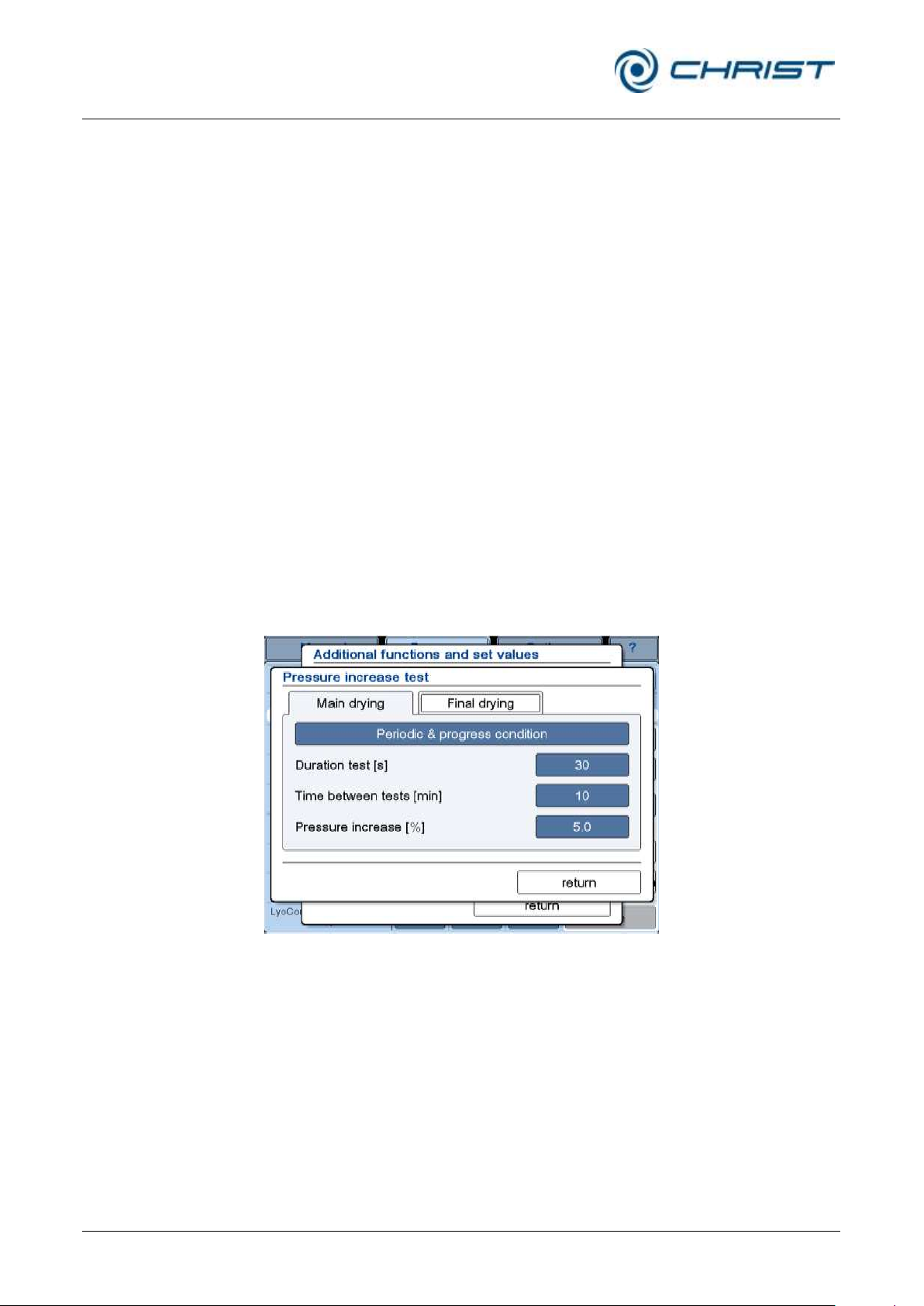
Freeze-dryer Alpha 1-4 LSCplus
Freeze-dryer Alpha 2-4 LSCplus
6 Operation
72 / 131
Version 01/2011, Rev. 2.3 of 03/07/2017 • sb
Translation of the original operating manual
Otherwise, a process message will be issued, the current section will be
extended, and further pressure increase tests will be executed
periodically until the condition is fulfilled. If the actual value exceeds the
set value before the preselected time has elapsed, the test will be
aborted in order to prevent the product from thawing. If the value is
exceeded, the pressure increase test will be aborted in order to prevent
the product from thawing.
• Periodic & progress condition:
This variant is a combination of the possibilities that are described
above. The test will be performed periodically during the entire main or
final drying phase. The maximum pressure increase is limited to 100%,
referring to the actual value at the beginning of the measurement. If this
value is exceeded before the test time has elapsed, the particular test
will be aborted in order to prevent the product from thawing. If the last
two tests have been passed (amount of pressure increase below the
limit "Pressure increase"), the drying process will be considered
complete at the current conditions. Thus the progress condition for
switching to the next section is fulfilled and the next section will be
initiated.
Otherwise, a process message will be issued, the current section will be
extended, and further pressure increase tests will be executed
periodically until the condition is fulfilled.
• Disabled:
No pressure increase test will be executed during the main or final
drying phase. There will be no evaluation.
Fig. 64: Dialog box "Pressure increase test" in the program mode
Page 73
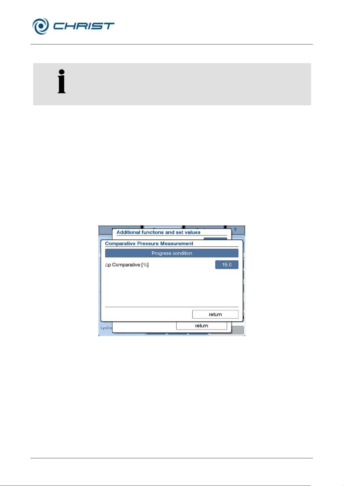
Freeze-dryer Alpha 1-4 LSCplus
Freeze-dryer Alpha 2-4 LSCplus
6 Operation
Version 01/2011, Rev. 2.3 of 03/07/2017 • sb
73 / 131
Translation of the original operating manual
NOTE
The indication of the measurement value "dp Comp" can be configured in
chapter 6.5.1.1 - "Main window "Manual"" under "Actual values of the
current process" in the dialog box "Select actual value".
Option: Comparative pressure measurement (see chapter 6.6 - "Optional
extensions")
The comparative pressure measurement can be activated or deactivated by
pressing the button in the dialog box.
• Progress condition:
If the difference between the readings of the Pirani and the capacitive
vacuum sensor at the end of the last main drying section is below the
limit "p Comparative", the drying process will be considered complete
at the current conditions. Thus the progress condition for switching to
the next section is fulfilled and the next section will be initiated.
Otherwise, a process message will be issued, the current section will be
extended, and the current section will be extended until the condition is
fulfilled.
• Disabled:
There will be no comparative pressure measurement during the main
drying phase. There will be no evaluation.
Fig. 65: Dialog box "Comparative pressure measurement"
Page 74
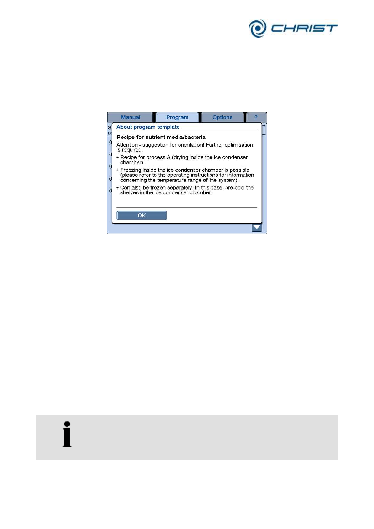
Freeze-dryer Alpha 1-4 LSCplus
Freeze-dryer Alpha 2-4 LSCplus
6 Operation
74 / 131
Version 01/2011, Rev. 2.3 of 03/07/2017 • sb
Translation of the original operating manual
NOTE
It is possible to switch to the manual mode during a program run, e.g. in
order to edit a program during the runtime. The point of time for continuing
the program run can be defined by selecting the desired start section and
a start time.
Program templates (2)
The PGMplus programmer module offers 14 different program templates
that include recipes for all kinds of freeze-drying applications. They are
suggestions for orientation purposes and must be adapted to the specific
area of application of the freeze-dryer.
Following the selection of a program template, a window containing
information concerning the drying process will be displayed.
Fig. 66: Information concerning the program template
(here: a recipe for nutrient media/bacteria)
After the conformation of the information, the program template will be
displayed.
• Similar to a blank program, sections can be added or deleted and the
set values can be adapted accordingly.
6.5.3.2 Editing a program
An existing program can be modified as long as it has not been loaded.
• Select the program to be edited from the list in the main window
“Program”.
• Press the button with the program name in order to call up a window
that displays the program data.
• Perform the desired modifications and save the program (see chapter
6.5.3.1 - "Creating a program").
• Close the dialog box by pressing the “Program” button.
The program has now been changed in the existing program storage
location.
Page 75
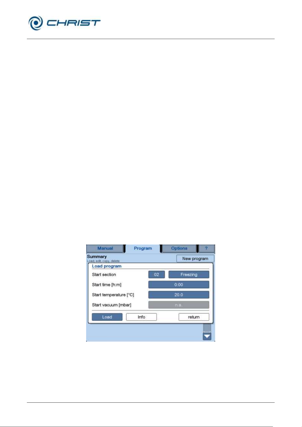
Freeze-dryer Alpha 1-4 LSCplus
Freeze-dryer Alpha 2-4 LSCplus
6 Operation
Version 01/2011, Rev. 2.3 of 03/07/2017 • sb
75 / 131
Translation of the original operating manual
6.5.3.3 Copying a program
If a new program is to be created based on an already existing program,
the already existing program can be copied. A free program storage
location must be available for this purpose.
• Select the program to be copied from the list in the main window
"Program".
• Press the button with the program name in order to call up a window
with the program data.
• Press the button “Copy program” in order to create a copy of the
existing program.
• Edit and save the copy (see chapter 6.5.3.1 - "Creating a program").
• Close the dialog box by pressing the “Program” button.
The program will be automatically assigned to the first free program storage
location.
6.5.3.4 Loading a program
If a freeze-drying process is to be executed and controlled by a program,
the program must be loaded.
• Call up the main window "Program". This window includes a list of all
the programs that are saved.
• Press the button "Load" behind the program name. A dialog box will be
displayed in which the start section, the start time or the start
temperature can be adapted to any specific needs. The "Info" button
can be used to call up a brief description of the active program,
including information concerning the remaining runtime and the end of
the program. It also enables a graphical representation of the process
sequence.
Fig. 67: Dialog box "Load program"
• Press the button "Load" in order to accept the program data. The
• Press the button "Program start" in order to start the freeze-drying
display switches to the standard user interface.
process.
Page 76
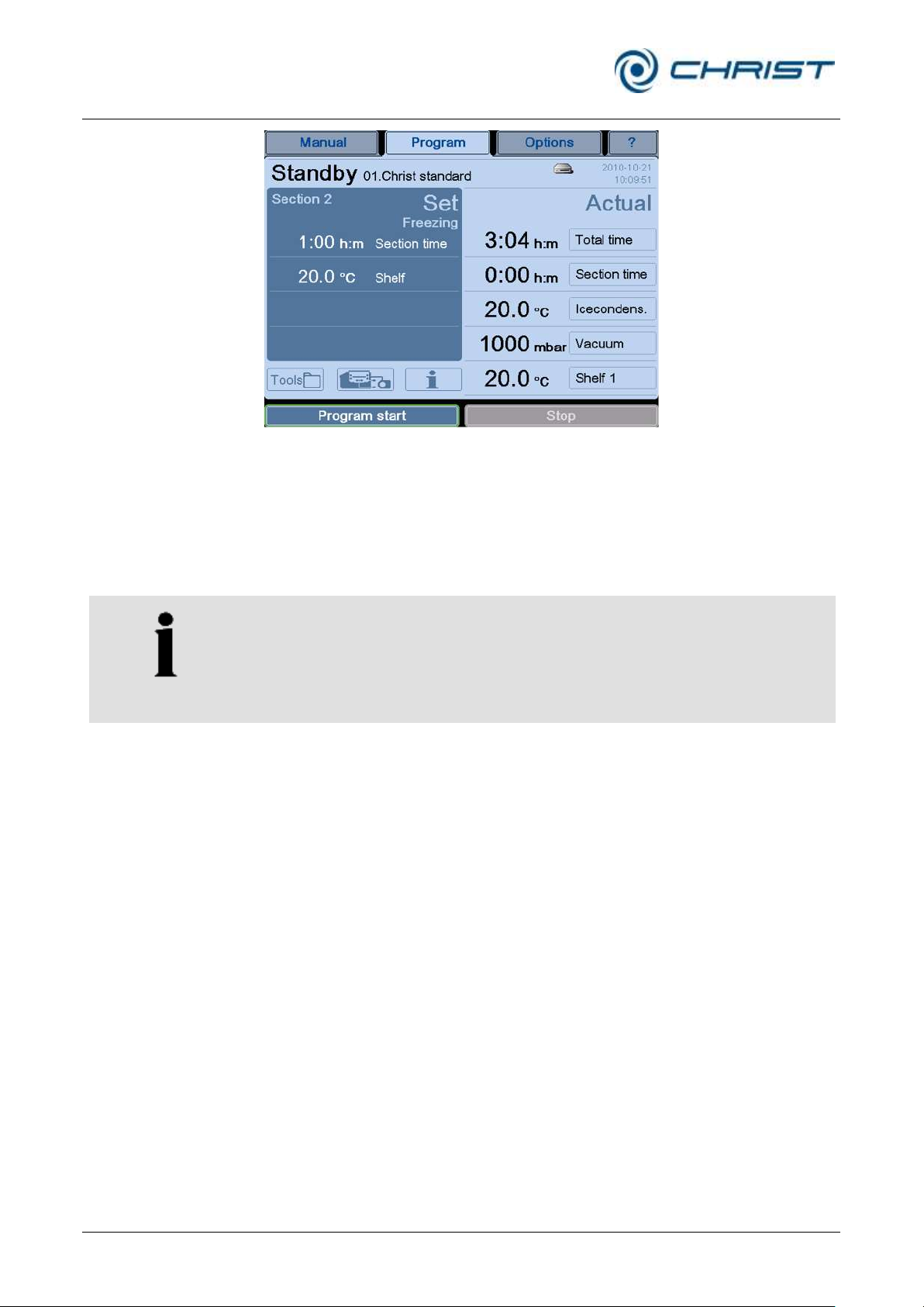
Freeze-dryer Alpha 1-4 LSCplus
Freeze-dryer Alpha 2-4 LSCplus
6 Operation
76 / 131
Version 01/2011, Rev. 2.3 of 03/07/2017 • sb
Translation of the original operating manual
NOTE
The program starts with section 02 "Freezing" by default. If, however,
section 01 "Load" is to be used as the starting point of the program, this
section must be selected manually. In this case, the button "Program
continue" will be displayed after the start of the program. When the
precooling (loading) process is complete, this button must be pressed in
order to continue with the program.
Fig. 68: The freeze-drying process can be started with the aid of the button “Program start”.
• During the freeze-drying process, the description of the active program
can also be called up from the main window "Program" and via the
button "Info".
• When the "Stop" button is pressed, the freeze-dryer switches to the
standby – manual freezing mode.
6.5.3.5 Deleting a program
The PGMplus programmer module offers 32 program storage locations. If
they are all occupied, a program must be deleted before a new one can be
created.
• Select the program to be deleted from the list in the main window
"Program".
• Press the button with the program name in order to call up a window
with the program data.
• Press the button “Delete program”. The system will then display a dialog
box with an enquiry.
• Following the confirmation of the enquiry, the program will be deleted.
The program storage location on the list is now empty and the number is
not shown on the list.
Page 77

Freeze-dryer Alpha 1-4 LSCplus
Freeze-dryer Alpha 2-4 LSCplus
6 Operation
Version 01/2011, Rev. 2.3 of 03/07/2017 • sb
77 / 131
Translation of the original operating manual
6.6 Optional extensions
Comparative pressure measurement
see also chapter 6.5.3.1 - "Creating a program", button ">>more"
During the sublimation, i.e. when the concentration of water vapour
molecules is rather high in the atmosphere, the value that is provided by
the gas-type-dependent vacuum sensor of the "Pirani" type (e.g. Thyracont
VSP62/63) deviates from the value that is provided by a capacitive vacuum
sensor (e.g. MKS 722B). When the proportion of water vapour molecules
decreases towards the end of the main drying phase, the two sensors fall
increasingly in line with one another. This difference will be evaluated and
used as an indicator for identifying the drying end of the main drying phase.
Leakage test
see also chapter 6.5.3.1 - "Creating a program"
The leakage test enables the chamber of the freeze-dryer to be tested for
tightness in view of any gaseous or liquid media. Since absolutely tight
components simply do not exist, a leak rate is determined. The parameters
for the leakage test have been developed by Martin Christ Gefriertrocknungsanlagen specifically for freeze-dryers. In a first step, these
parameters (vacuum, ice condenser temperature) must be reached. It is not
until the conditions are fulfilled that the pressure control valve closes. Then,
the actual leakage test is performed in a second step. The leak rate that is
calculated after the end of the test provides information concerning the
tightness of the system.
PGMplus programmer module
see also chapter 6.5.2.1 - "Entering set values in the manual mode"
The PGMplus programmer module enables the fully automatic execution of
an entire freeze-drying process under reproducible conditions.
Pressure increase test
see also chapter 6.5.3 - "Option: freeze-drying with the PGMplus
programmer module", button ">>more"
The pressure increase test can only be carried out with the double-
chamber method. During the pressure increase test, the intermediate valve
prevents the flow of steam from the drying chamber to the ice condenser so
that the water vapour of the sublimation cannot flow off. The result is a
more or less distinct pressure increase that is measured in the product
chamber. The pressure increase test is used as a criterion for the automatic
switching between main drying and final drying and also for identifying the
end of the process.
USB process recorder
see also chapter 6.5.2 - "Manual freeze-drying", dialog box "Tools"
This feature enables the recording of a running process on a USB storage
medium. After the end of the process recording, the process data can be
viewed on the PC with LyoLogplus and be printed. It is also possible to
import the data directly into an Excel file.
Page 78

Freeze-dryer Alpha 1-4 LSCplus
Freeze-dryer Alpha 2-4 LSCplus
6 Operation
78 / 131
Version 01/2011, Rev. 2.3 of 03/07/2017 • sb
Translation of the original operating manual
Lyo Control measuring system
The Lyo Control measuring system can be used to determine the
crystallisation state of the product. In the liquid state, the electrical
resistance is very low. During the freezing process, the resistance
increases. The LyoRx control sensor measures the electrical resistance.
LyoLogplus data logging software
LyoLogplus is a data logging software program by Martin Christ
Gefriertrocknungsanlagen GmbH that is specifically adapted to the
requirements of freeze-drying processes. Apart from the graphical
representation of the measurement data of currently running processes, it
also enables the data export for additional evaluation.
LPCplus SCADA system
The Christ LPCplus system consists of the Supervisory Control And Data
Acquision (SCADA) software program by Martin Christ Gefriertrocknungsanlagen GmbH and a dedicated PC. The system is connected to the
LSCplus controller of the freeze-dryer via Ethernet LAN and provides the
operation of all of the freeze-drying functions as well as process recording
(measurement data and process events), process documentation and data
backup. Furthermore, it enables the comfortable administration of freeze-
drying programs/recipes and users.
6.7 Switching the freeze-dryer OFF
The freeze-dryer must be in the standby status.
• Switch the freeze-dryer off by pressing the mains switch.
Page 79

Freeze-dryer Alpha 1-4 LSCplus
Freeze-dryer Alpha 2-4 LSCplus
7 Malfunctions and error correction
Version 01/2011, Rev. 2.3 of 03/07/2017 • sb
79 / 131
Translation of the original operating manual
Type of error
Possible reason
Correction
No indication on the display
• No power in the mains supply
(see chapter 7.1.1 - "Power
failure").
• Power cord is not plugged in.
• Fuses have tripped.
• The mains power switch is set
to off.
• Check the mains power supply
fuse.
• Plug in the power cord correctly.
• Check the on-site fuses
• Switch mains power switch ON.
The touchpanel does not react at all
or it does not react correctly
• The sensitivity of the touchpanel
is misadjusted.
• Contact the service department
(see chapter 7.3 - "Service
contact")
The password input fails
• The password is not correct.
• Inform the administrator.
• If you have lost the administrator
password: contact the service
department (see chapter 7.3 "Service contact")
Insufficient vacuum
• Incorrect connection of the
small flange connection(s).
• Loosen the connection. Place
the centring ring with the inner
sealing ring in a centred manner
between the flange connections
and connect it with the clamping
ring. Ensure that the centring
ring neither slips out of place nor
gets jammed.
• Dirty or damaged lid or door
seal.
• Clean the lid or door seal and
replace it if necessary.
• The ground-in stopper of the
attached drying chamber is not
installed correctly.
• Grease the ground-in stopper
evenly and over the entire
sealing surface with vacuum
grease.
Leakage in the media drain valve
• The media drain valve is soiled
with drying residues or wool
particles from cleaning cloths.
• The O-rings are worn
• Clean the media drain valve (see
chapter 8.1.3 - "Aeration valve,
media drain valve")and replace it
if necessary.
• Replace the O-rings.
Leakage in a rubber valve
• The valve is soiled.
• Check the valves individually
(see chapter 7.1.2.4 - "Rubber
valves")
7 Malfunctions and error correction
Malfunctions are displayed in the dialog box "Process & equipment
messages" (see chapter 7.2 - "Process and error messages"). An acoustic
signal sounds when an error message is generated.
• Eliminate the source of the problem (see the following chapter).
7.1 General malfunctions
• Acknowledge the error message.
Page 80

Freeze-dryer Alpha 1-4 LSCplus
Freeze-dryer Alpha 2-4 LSCplus
7 Malfunctions and error correction
80 / 131
Version 01/2011, Rev. 2.3 of 03/07/2017 • sb
Translation of the original operating manual
Type of error
Possible reason
Correction
The displayed vacuum value is not
correct
• Incorrect calibration
• The vacuum sensor is soiled
(e.g. due to water residues)
• The vacuum sensor is
defective.
• Calibrate the vacuum sensor
(see the separate operating
instructions of the vacuum
sensor).
• Clean the vacuum sensor.
• Check the vacuum display with
the aid of a reference device (if
available).
• see chapter 7.1.2.5 - "Vacuum
sensor"
The vacuum pump is not activated
• See the separate operating
instructions of the vacuum
pump.
• See the separate operating
instructions of the vacuum
pump.
Insufficient ice condenser or shelf
temperature
• The overpressure switch of the
refrigeration unit has tripped.
• The thermal circuit breaker has
tripped.
• Let the unit cool down.
• Ensure sufficient air circulation
(see chapter 7.1.3 - "Insufficient
ice condenser temperature")
NOTE
If it is impossible to eliminate the errors, contact the Christ service
department!
7.1.1 Power failure
The control system continues with the process after a power failure. The
preselected conditions remain saved even during a process run.
In the event of a power failure in the drying phase, the batch may become
unusable. Whether the batch can be saved or not depends on the drying
phase in which the product was when the power failure occurred.
• In the final drying phase, the product has reached a residual moisture
content of approx. 5%. Below this value, the product is generally not
damaged even if the power failure lasts for a longer period of time.
• If the product is in the main drying phase, we recommend aerating the
unit, removing the product, and storing it in a deep-freeze. The
defrosted condensate must be drained off prior to the next start.
Page 81
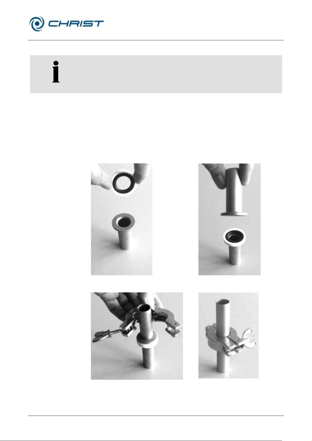
Freeze-dryer Alpha 1-4 LSCplus
Freeze-dryer Alpha 2-4 LSCplus
7 Malfunctions and error correction
Version 01/2011, Rev. 2.3 of 03/07/2017 • sb
81 / 131
Translation of the original operating manual
NOTE
The vacuum checks must be carried out when the ice condenser is frozen.
Fig. 69: Small flange and centring ring
Fig. 70: Small flange with centring ring
and small flange
Fig. 71: Attaching the clamping ring
Fig. 72: Tightened clamping ring
7.1.2 Insufficient vacuum
7.1.2.1 Small flange connections
Leakages are often due to improper small flange connections between the
various components and hose connections or to leakages in the valves.
• Loosen the connection and place the centring ring (with sealing ring
inside) in a centred manner between the flange connections.
• Seal the connection with the clamping ring by tightening the wing nut.
• Ensure that the centring ring neither slips out of place nor gets jammed.
Page 82

Freeze-dryer Alpha 1-4 LSCplus
Freeze-dryer Alpha 2-4 LSCplus
7 Malfunctions and error correction
82 / 131
Version 01/2011, Rev. 2.3 of 03/07/2017 • sb
Translation of the original operating manual
NOTE
The inspection of the valve must be carried out by qualified specialist
personnel (see chapter 7.3 - "Service contact").
7.1.2.2 Aeration valve, media drain valve
A malfunction of the aeration valve or the media drain valve may have
several causes. One potential source are contaminants such as product
residues within the valve.
• Switch the freeze-dryer off and disconnect the mains plug.
• Clean the valve (see chapter 8.1.3 - "Aeration valve, media drain
valve").
• Put the freeze-dryer into operation again.
If there is still a leakage, the freeze-dryer must be checked by qualified
specialist personnel (see chapter 7.3 - "Service contact").
7.1.2.3 Pressure control valve
A malfunction of the pressure control valve may have several causes.
7.1.2.4 Rubber valves
In order to identify a leaking rubber valve, the valves must be checked
individually:
• Remove the rubber valve and seal the connection at the drying
chamber with a rubber stopper.
• Check the tightness under vacuum until the leaking valve has been
localised.
• Clean the valve or replace it if necessary.
7.1.2.5 Vacuum sensor
Vacuum sensors have a limited service life and can be ordered as spare
parts (e.g. VCP 63, order no. 312011).
Functional test:
• Connect the vacuum sensor directly to the suction side connector of the
vacuum pump.
If a final pressure of at least 0.011 mbar is reached (with a vacuum pump
that has reached its operating temperature), the sensor and the vacuum
pump are OK.
Page 83

Freeze-dryer Alpha 1-4 LSCplus
Freeze-dryer Alpha 2-4 LSCplus
7 Malfunctions and error correction
Version 01/2011, Rev. 2.3 of 03/07/2017 • sb
83 / 131
Translation of the original operating manual
CAUTION
Ensure sufficient ventilation. Do not place any paper, cloth, or similar
material behind or under the unit, since otherwise the air circulation will be
impaired.
7.1.3 Insufficient ice condenser temperature
The refrigeration unit is equipped with a protective device against
overpressure in the refrigeration system and with a thermal motor
protection switch.
The protective devices trip
• when the ambient temperature is too high
• when the air circulation of the heat exchanger of the refrigeration
system is insufficient
• when the refrigeration system is overloaded.
In these cases, the refrigeration unit will be switched off automatically. If the
permissible operating conditions are re-established after a cool-down
phase of several minutes, the refrigeration unit will be switched on again
automatically.
The malfunctions are displayed in the process and equipment information
window.
The minimum ice condenser temperature of approx. -55°C or approx. –
85°C (depending on the type of freeze-dryer) is reached when the ice
condenser is not loaded and the ice condenser chamber is evacuated.
7.2 Process and error messages
The LSCplus control system displays the complete process and error
messages (see chapter 6.5.1.1 - "Main window "Manual"", dialog box
"Process and equipment messages"), which is why they are not included in
this operating manual.
You can order these documents from our service department.
Page 84

Freeze-dryer Alpha 1-4 LSCplus
Freeze-dryer Alpha 2-4 LSCplus
7 Malfunctions and error correction
84 / 131
Version 01/2011, Rev. 2.3 of 03/07/2017 • sb
Translation of the original operating manual
NOTE
If you would like to utilise our after-sales-service, please state the type of
your freeze-dryer and its serial number.
7.3 Service contact
In the event of queries, malfunctions, or spare part enquiries:
From Germany:
Contact
Martin Christ Gefriertrocknungsanlagen GmbH
An der Unteren Söse 50
37520 Osterode (Germany)
Tel. +49 (0) 55 22 / 50 07-44 44
E-mail: [email protected]
Outside Germany:
Contact our agency in your country. All agencies are listed at
www.martinchrist.de [Sales Partners]
Page 85

Freeze-dryer Alpha 1-4 LSCplus
Freeze-dryer Alpha 2-4 LSCplus
8 Maintenance and service
Version 01/2011, Rev. 2.3 of 03/07/2017 • sb
85 / 131
Translation of the original operating manual
CAUTION
If corrosion or other damage occurs due to improper care, the
manufacturer cannot be held liable or subject to any warranty claims.
8 Maintenance and service
The freeze-dryer and the accessories are subject to high mechanical
stress. Thorough maintenance performed by the user extends the service
life and prevents premature failure.
• Use soap water or other water-soluble, mild cleaning agents for
cleaning the freeze-dryer and the accessories.
• Do not use corrosive and aggressive substances.
• Do not use solvents.
• Do not use agents with abrasive particles.
• Do not expose the freeze-dryer or its accessories to intensive UV
radiation (e.g. sunlight) or thermal stress (e.g. by heat generators).
• Do not turn the unit upside down in order to clean it.
8.1 Maintenance
8.1.1 General
The general state of the freeze-dryer must be checked at regular intervals.
Any defects must be eliminated immediately! The following points are of
particular importance:
• dirt
• leaks
• corrosion
• bent system components
• loose screw and flange connections
• higher noise levels
• loose cables
• open cable ducts
• missing or illegible safety notes and hazard warnings
• missing or illegible inscriptions on components, pipes (direction of flow)
and cables
• etc.
Page 86
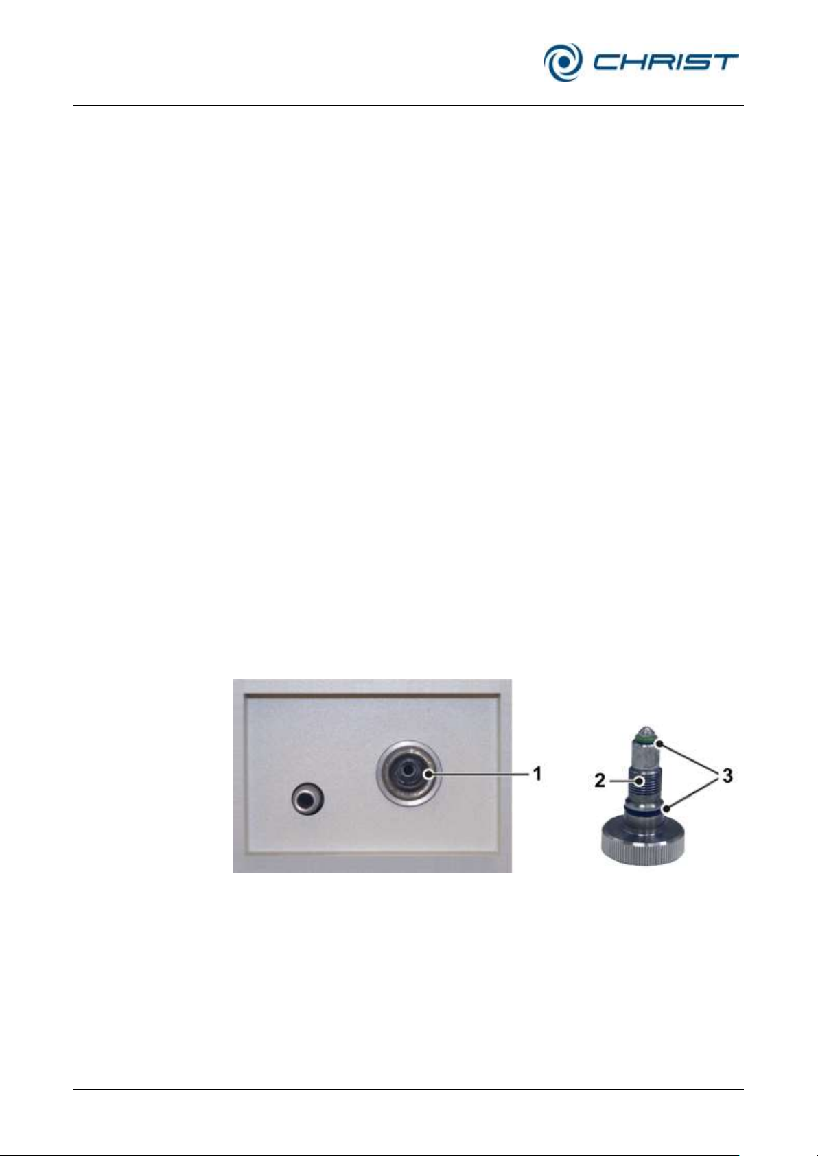
Freeze-dryer Alpha 1-4 LSCplus
Freeze-dryer Alpha 2-4 LSCplus
8 Maintenance and service
86 / 131
Version 01/2011, Rev. 2.3 of 03/07/2017 • sb
Translation of the original operating manual
1 Valve opening
2 Valve core
3 O-rings
Cleaning of the freeze-dryer
• Switch the freeze-dryer off by actuating the mains power switch and
disconnect the power cord from the wall outlet before cleaning.
• If the freeze-dryer has been contaminated with toxic, radioactive, or
pathogenic substances, clean the inside immediately with a suitable
decontamination agent (depending on the type of contamination, see
chapter 8.2 - "Disinfection of the drying chamber and accessories").
• Remove product residues thoroughly with a cloth.
• Open the lid/drying chamber when the freeze-dryer is not in use so
8.1.2 Ice condenser chamber
moisture can evaporate.
Before each start-up, ensure that the ice condenser chamber is free from
water residues.
• Open the media drain valve to drain off any liquid. Then, close the
valve.
• If necessary, wipe the ice condenser chamber dry with a cloth.
8.1.3 Aeration valve, media drain valve
Contaminants such as product residues may lead to an insufficient vacuum.
In this case, the aeration valve and the media drain valve must be cleaned.
• Switch the freeze-dryer off and disconnect the mains plug.
• Remove the valve core.
• Clean the valve core and the opening with a moist cloth.
• Clean the O-rings and inspect them for any damage. Damaged O-rings
must be replaced.
Fig. 73: Valve opening and valve core with O-rings
(example, varies depending of the type of freeze-dryer)
• Reinsert the valve core.
• Put the freeze-dryer into operation again.
If the vacuum is still insufficient, the freeze-dryer must be checked by
qualified specialist personnel (see chapter 7.3 - "Service contact").
Page 87

Freeze-dryer Alpha 1-4 LSCplus
Freeze-dryer Alpha 2-4 LSCplus
8 Maintenance and service
Version 01/2011, Rev. 2.3 of 03/07/2017 • sb
87 / 131
Translation of the original operating manual
NOTE
Please refer to the separate operating manual of the vacuum pump!
8.1.4 Heat exchanger (only for air-cooled freeze-dryers)
A lamellar heat exchanger is used for cooling the refrigerant that is
compressed by the refrigeration unit. This air-cooled heat exchanger is
located at the back of the unit (see chapter 2.1.1 - "Functional and
operating elements").
Dust and dirt impair the cooling effect of the air flow. Dust on the lamellas
prevents the exchange of heat and, thereby, impairs the performance and
power of the refrigeration unit. Strong soiling may cause the unit to fail.
This is why the selected set-up location should be as clean as possible.
• Check the heat exchanger at least once per month for soiling and clean
it if necessary.
• Please contact the Christ service department if you have any queries
8.1.5 Vacuum pump
(see chapter 7.3 - "Service contact").
The stress of the vacuum pump in conjunction with a freeze-dryer is usually
not very high. This is why the recommendations in this operating manual
may differ from the information that is provided by the pump manufacturers.
Under normal operating conditions, the following maintenance tasks
concerning the vacuum pump must be performed at regular intervals:
• Check the oil level of the vacuum pump once per week. If necessary,
top it up with oil.
• Check the running pump for any unusual noise.
• Ensure that the pump has reached its operating temperature prior to
changing the oil.
• Perform the first oil change after approximately 100 operating hours.
• The other oil changes depend on the operating conditions. In general,
an interval of 500 to 1,000 operating hours is sufficient.
• Please contact the Christ service department if you have any queries
(see chapter 7.3 - "Service contact").
Page 88

Freeze-dryer Alpha 1-4 LSCplus
Freeze-dryer Alpha 2-4 LSCplus
8 Maintenance and service
88 / 131
Version 01/2011, Rev. 2.3 of 03/07/2017 • sb
Translation of the original operating manual
NOTE
Please refer to the separate operating manual of the vacuum pump and
the exhaust filter!
NOTE
Please refer to the separate operating manual of the vacuum sensor!
CAUTION
For the care of the accessories, special safety measures must be
considered as these are measures that will ensure operational safety at
the same time.
8.1.6 Exhaust filter (oil mist separator)
The oil mist that is emitted by the vacuum pump in quantities that depend
on the working pressure must be led to the outside or to an exhaust hood
or similar. If this is not possible, the pump must be equipped with an
exhaust filter (oil mist separator).
• Observe the liquid level in the collecting vessel of the filter.
• Remove the condensate in time (please refer to the information
8.1.7 Vacuum sensor
provided by the manufacturer in the separate operating manual).
The vacuum sensor has only a limited service life. Especially carboncontaining substances, e.g. alcoholic compounds, reduce the service life
extremely.
• The vacuum sensor is maintenance-free.
8.1.8 Accessories
• Remove any soiling on the outside with a cloth.
Chemical reactions as well as stress-corrosion (combination of oscillating
pressure and chemical reaction) can affect or destroy the metal and plastic
parts. Barely detectable cracks on the surface can expand and weaken the
material without any visible signs.
Page 89

Freeze-dryer Alpha 1-4 LSCplus
Freeze-dryer Alpha 2-4 LSCplus
8 Maintenance and service
Version 01/2011, Rev. 2.3 of 03/07/2017 • sb
89 / 131
Translation of the original operating manual
DANGER
If dangerous materials (e.g. infectious and pathogenic substances) are
used, the freeze-dryer and accessories must be disinfected.
• Check the material regularly (at least once a month) for
– cracks
– visible damage of the surface
– pressure marks
– signs of corrosion
– other changes.
• Replace any damaged components immediately for your own safety.
• Immediately rinse off the accessories if any liquids that may cause
corrosion come into contact with them.
• Clean the accessories outside the freeze-dryer once a week or
preferably after each use.
8.2 Disinfection of the drying chamber and accessories
• Use commercially-available disinfectants such as, for example, Incidur,
Meliseptol, Sagrotan, Buraton, or Terralin (available at specialised
trade).
• The freeze-dryers and the accessories consist of various materials. A
possible incompatibility must be considered.
• Before using cleaning or decontamination agents that were not
recommended by us, contact the manufacturer to ensure that such a
procedure will not damage the freeze-dryer.
• Please contact us if you have any queries (see chapter 7.3 - "Service
contact").
Page 90

Freeze-dryer Alpha 1-4 LSCplus
Freeze-dryer Alpha 2-4 LSCplus
8 Maintenance and service
90 / 131
Version 01/2011, Rev. 2.3 of 03/07/2017 • sb
Translation of the original operating manual
DANGER
In the event of service work that requires the removal of the panels, there
is a risk of electric shock or mechanical injury. Only qualified specialist
personnel is authorised to perform this service work.
NOTE
If you would like to utilise our after-sales-service, please state the type of
your freeze-dryer and its serial number.
8.3 Service
The freeze-dryer is subject to high mechanical stress. In order to be able to
withstand this high level of stress, high-quality components were used
during the production of the freeze-dryer. Nevertheless, wear cannot be
excluded and it may not be visible from the outside.
This is why we recommend having the freeze-dryer checked by the
manufacturer during an inspection once per year.
Information and appointments:
From Germany:
Contact
Martin Christ Gefriertrocknungsanlagen GmbH
An der Unteren Söse 50
37520 Osterode (Germany)
Tel. +49 (0) 55 22 / 50 07-44 44
E-mail: [email protected]
Outside Germany:
Contact our agency in your country. All agencies are listed at
www.martinchrist.de [Sales Partners]
8.4 Return of defective parts
Although we exercise great care during the production of our products, it
may be necessary to return a unit or accessory to the manufacturer.
In order to ensure the quick and economical processing of returns of
freeze-dryers, rotational vacuum concentrators, spare parts, or
accessories, we require complete and extensive information concerning the
process. Please fill in the following forms completely, sign them, enclose
them with the return package, and send them together with the product to:
Martin Christ Gefriertrocknungsanlagen GmbH
An der Unteren Söse 50
37520 Osterode (Germany)
Page 91

Freeze-dryer Alpha 1-4 LSCplus
Freeze-dryer Alpha 2-4 LSCplus
8 Maintenance and service
Version 01/2011, Rev. 2.3 of 03/07/2017 • sb
91 / 131
Translation of the original operating manual
NOTE
We will return the part/unit if no declaration of decontamination is provided!
NOTE
The part/unit must be packaged in a transport-safe manner. Please use
the original packaging for the unit, if at all possible.
If the product is dispatched to us in unsuitable packaging, you will be
charged the cost for returning it to you in new packaging.
1. Declaration of decontamination
As a certified company and due to the legal regulations for the
protection of our employees and of the environment, we are obliged to
certify the harmlessness of all incoming goods. For this purpose, we
require a declaration of decontamination.
• The form must be filled in completely and signed by authorised and
specialised personnel only.
• Affix the original form in a clearly visible manner to the outside of the
packaging.
2. Form for the return of defective parts
This form is for the product-related data. They facilitate the assignment,
and they enable the quick processing of the return. If several parts are
returned together in one packaging, please enclose a separate problem
description for every defective part.
• A detailed problem description is necessary in order to perform the
repair quickly and economically.
• Upon request, we will prepare and submit to you a cost estimate
prior to performing the repair. Please confirm such cost estimate
within 14 days. If the cost estimate has still not been confirmed after
4 weeks, we will return the defective part/unit. Please note that you
must bear the incurred costs.
The forms can be downloaded online from
www.martinchrist.de [Service] [Overhaul, repair and leak testing].
Page 92

Freeze-dryer Alpha 1-4 LSCplus
Freeze-dryer Alpha 2-4 LSCplus
9 Disposal
92 / 131
Version 01/2011, Rev. 2.3 of 03/07/2017 • sb
Translation of the original operating manual
9 Disposal
9.1 Disposal of the freeze-dryer
Martin Christ Gefriertrocknungsanlagen GmbH is a registered manufacturer
of electric and electronic devices that are solely intended for commercial
use.
• Comply with all local rules and regulations.
9.2 Disposal of the packaging
• Dispose of the packaging, after having separated the individual
materials.
• Comply with all local rules and regulations.
Page 93

Freeze-dryer Alpha 1-4 LSCplus
Freeze-dryer Alpha 2-4 LSCplus
10 Technical data
Version 01/2011, Rev. 2.3 of 03/07/2017 • sb
93 / 131
Translation of the original operating manual
Manufacturer:
Martin Christ Gefriertrocknungsanlagen GmbH
An der Unteren Söse 50
37520 Osterode
Germany
Type:
Alpha 1-4 LSCplus
Alpha 2-4 LSCplus
Part number:
102141
102142
Performance data
Alpha 1-4 LSCplus
Alpha 2-4 LSCplus
Ice condenser
- capacity:
- performance:
- temperature:
- chamber volume:
4 kg max
4 kg / 24 h max
approx. –55°C
approx. 6.5 l
4 kg max
4 kg / 24 h max
approx. –85°C
approx. 6.5 l
Temperature of the ice condenser
during hot-gas defrosting:
approx. +60°C
approx. +60°C
Possible shelf temperatures
( single chamber method):
freezing and drying inside the ice
condenser chamber
approx. –25°C to +60°C
approx. –35°C to +60°C
Possible shelf temperatures
( double chamber method):
drying outside the ice condenser
chamber
Room temperature to +60°C
Room temperature to +60°C
Max. shelf surface area
( single chamber method):
drying inside the ice condenser
chamber
1 shelf, 200 mm
A
total
=0.031 m2
1 shelf, 200 mm
A
total
=0.031 m2
Max. shelf surface area
( double chamber method):
drying outside the ice condenser
chamber
drying in injection vials with sealing
under vacuum or nitrogen
atmosphere outside the ice
condenser chamber
drying in round bottom flasks
10 shelves, Ø 200 mm each
A
total
=0.31m2
or
5 shelves, 375 mm each
A
total
=0.55 m2
4 shelves, 250 mm each
A
total
=0.186 m2
12 pieces or 24 pieces
10 shelves, Ø 200 mm each
A
total
=0.31m2
or
5 shelves, 375 mm each
A
total
=0.55 m2
4 shelves, 250 mm each
A
total
=0.186 m2
12 pieces or 24 pieces
10 Technical data
Page 94

Freeze-dryer Alpha 1-4 LSCplus
Freeze-dryer Alpha 2-4 LSCplus
10 Technical data
94 / 131
Version 01/2011, Rev. 2.3 of 03/07/2017 • sb
Translation of the original operating manual
Connection requirements
(without vacuum pump and
accessories)
Alpha 1-4 LSCplus
Alpha 2-4 LSCplus
Electrical connection:
1 x 230V / 50-60 Hz
1 x 230V / 50-60 Hz
Protection class:
I
I
IP protection category according to
DIN 60529:
11
11
Apparent power:
0.85 kVA
1.6 kVA
Nominal current:
4.0 A
7.0 A
Mains fuse:
10 A F
12 A F
Pressure control valve connection:
230 V, 50/60 Hz, 20 VA max.
230 V, 50/60 Hz, 20 VA max.
Vacuum pump connection:
230 V, 50/60 Hz, 4.5 A max.
230 V, 50/60 Hz, 3.0 A max.
Filling quantity
Alpha 1-4 LSCplus
Alpha 2-4 LSCplus
Refrigerant:
filling quantity / CO2 equivalent
- R290:
- R404A:
- R508:
-160 g / 0.60 t
22 g / 0.26 t
12 g / < 0.01 t
130 g / 0.49 t
26 g / 0.31 t
Physical data (without vacuum
pump and accessories)
Alpha 1-4 LSCplus
Alpha 2-4 LSCplus
Dimensions
- height:
- width:
- depth:
415 mm
390 mm
555 mm + 80 mm vacuum
connection
415 mm
390 mm
555 mm + 80 mm vacuum
connection
Weight:
approx. 48 kg
approx. 60 kg
Noise level
according to DIN 45635:
54 dB(A)
54 dB(A)
EMC according to EN 55011:
Class B
Class B
Heat emission:
0.6 kW min.
1.1 kW max.
1.1 kW min.
1.6 kW max.
Equipment connections
Alpha 1-4 LSCplus
Alpha 2-4 LSCplus
Vacuum connection:
Small flange connection DN25KF
(ISO 28403, DIN 2861)
Small flange connection DN25KF
(ISO 28403, DIN 2861)
Media drain valve:
Hose nozzle DN10
(outside diameter 12 mm)
Hose nozzle DN10
(outside diameter 12 mm)
Aeration valve:
Hose nozzle DN6
(outside diameter 10 mm max.)
Hose nozzle DN6
(outside diameter 10 mm max.)
Vacuum sensor:
SUB D-9
VSP 63
SUB D-9
VSP 63
Data interface (LAN):
RJ 45
RJ 45
Page 95

Freeze-dryer Alpha 1-4 LSCplus
Freeze-dryer Alpha 2-4 LSCplus
10 Technical data
Version 01/2011, Rev. 2.3 of 03/07/2017 • sb
95 / 131
Translation of the original operating manual
Special equipment: water
cooling system
Alpha 1-4 LSCplus
Alpha 2-4 LSCplus
Part number:
102143
102144
Cooling water consumption:
max. 0.16 m3/h
max. 0.20 m3/h
Heat carried off via the cooling
water:
1.1 kW
1.6 kW
Cooling water feed flow
connection:
R3/4" with hose nozzle DN13
R3/4" with hose nozzle DN13
Cooling water return flow
connection:
R3/4" with hose nozzle DN13
R3/4" with hose nozzle DN13
10.1 Umgebungsbedingungen
10.1 Ambient conditions
10.1 Umgebungsbedingungen
• The figures are valid for an ambient temperature of +20°C.
• Allowable ambient temperature +10 °C to +25 °C.
• Max. humidity 85% (non-condensing) at +25°C.
10.2 Technical documentation
The technical documentation of this freeze-dryer (e.g. circuit diagram,
cooling system ) and the safety data sheets of the manufacturers of
refrigerant and heat transfer medium is not attached to this operating
manual.
You can order these documents from our service department.
Page 96
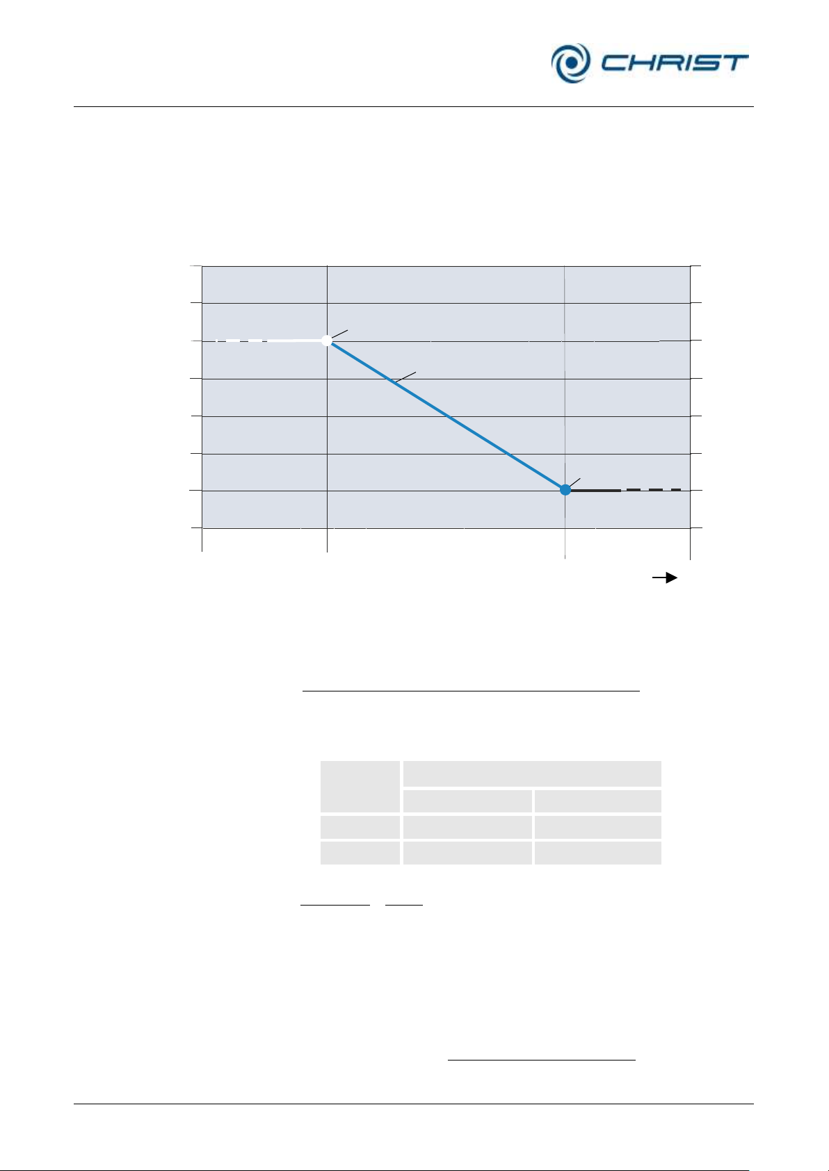
Freeze-dryer Alpha 1-4 LSCplus
Freeze-dryer Alpha 2-4 LSCplus
11 Appendix
96 / 131
Version 01/2011, Rev. 2.3 of 03/07/2017 • sb
Translation of the original operating manual
C/min][
secsec
secsec
tioncurrentoftimetion
tionpreviousofvaluesettioncurrentofvalueset
gradient
C][sec gradient time sectionelapsedtionpreviousofvaluesetvaluesetcontrol
Example:
Section
Set values
Section time [h:min]
Temperature [°C]
Preceding
...
30
Current
1:00
60
C/min 0.5
min60
30
min60
3060
CCC
gradient
C C/.CvaluesetControl
t
45min50min3030
min)30(
][ 10
sec
.)sec.(10.sec(10
.)sec.(10
mbarvaluesetcontrol
timetionelapsed
sectioncurrentoftimesection
tprevvaluesetLOGtcurrentvaluesetLOG
tprevvaluesetLOG
T/°C
t/h
1000
100
10
1
0.1
0.01
0.001
0.0001
+40
+30
+20
+10
0
-10
-20
-30
Pressure/mbar
Set value of the previous section
Course of the shelf temperature
control set value
Set value of the
current section
Previous
section
Current
section
Following
section
11 Appendix
11.1 Mathematical relations
The automatic processes in the “Programmer module” menu (see chapter
6.5.3 - "Option: freeze-drying with the PGMplus programmer module") are
based on the following considerations:
Fig. 74: Graphical representation of the course of the control set value
Calculation of the control set value and of the gradient for the
temperature:
After an elapsed section time of 30 minutes, for example, the control set
value for the temperature is:
Calculation of the control set value for the vacuum:
Page 97
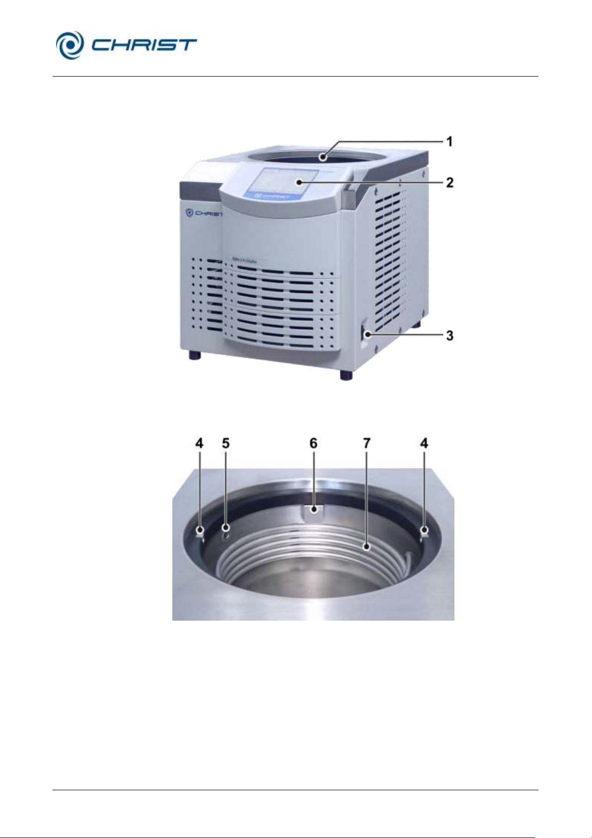
Freeze-dryer Alpha 1-4 LSCplus
Freeze-dryer Alpha 2-4 LSCplus
11 Appendix
Version 01/2011, Rev. 2.3 of 03/07/2017 • sb
97 / 131
Translation of the original operating manual
1 Ice condenser
chamber with an
internal ice condenser
2 User interface
3 Mains power switch
4 Contact piece
5 Vacuum sensor
6 Pipe connection of the
vacuum pump (behind
the cover plate)
7 Ice condenser
11.2 Brief operating instructions
Functional and operating elements
Fig. 75: Total view of the freeze-dryer
Fig. 76: Ice condenser chamber
Page 98
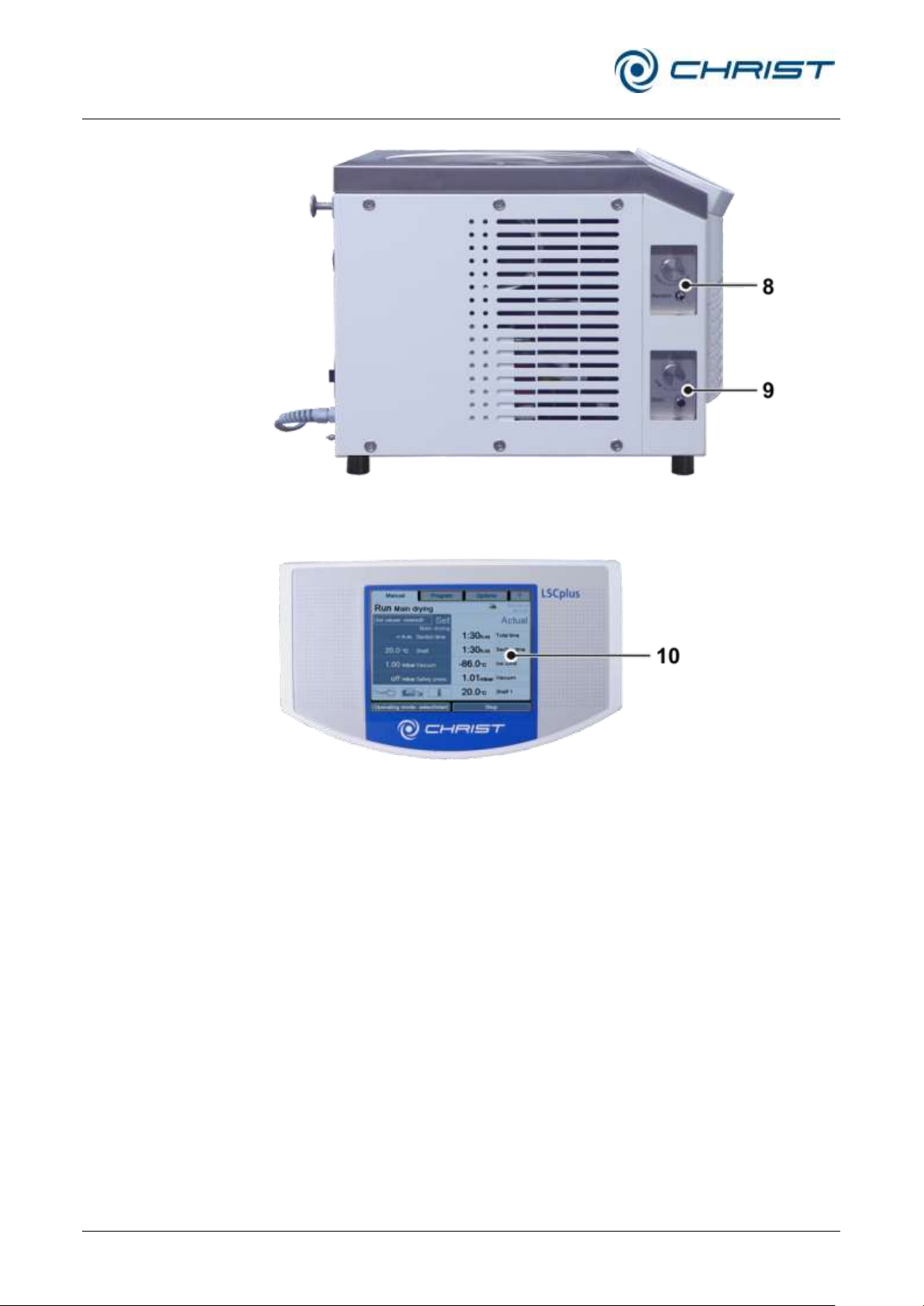
Freeze-dryer Alpha 1-4 LSCplus
Freeze-dryer Alpha 2-4 LSCplus
11 Appendix
98 / 131
Version 01/2011, Rev. 2.3 of 03/07/2017 • sb
Translation of the original operating manual
8 Aeration valve
9 Media drain valve
10 Touchpanel
Fig. 77: Left side of the freeze-dryer
Fig. 78: User interface with touchpanel
Page 99
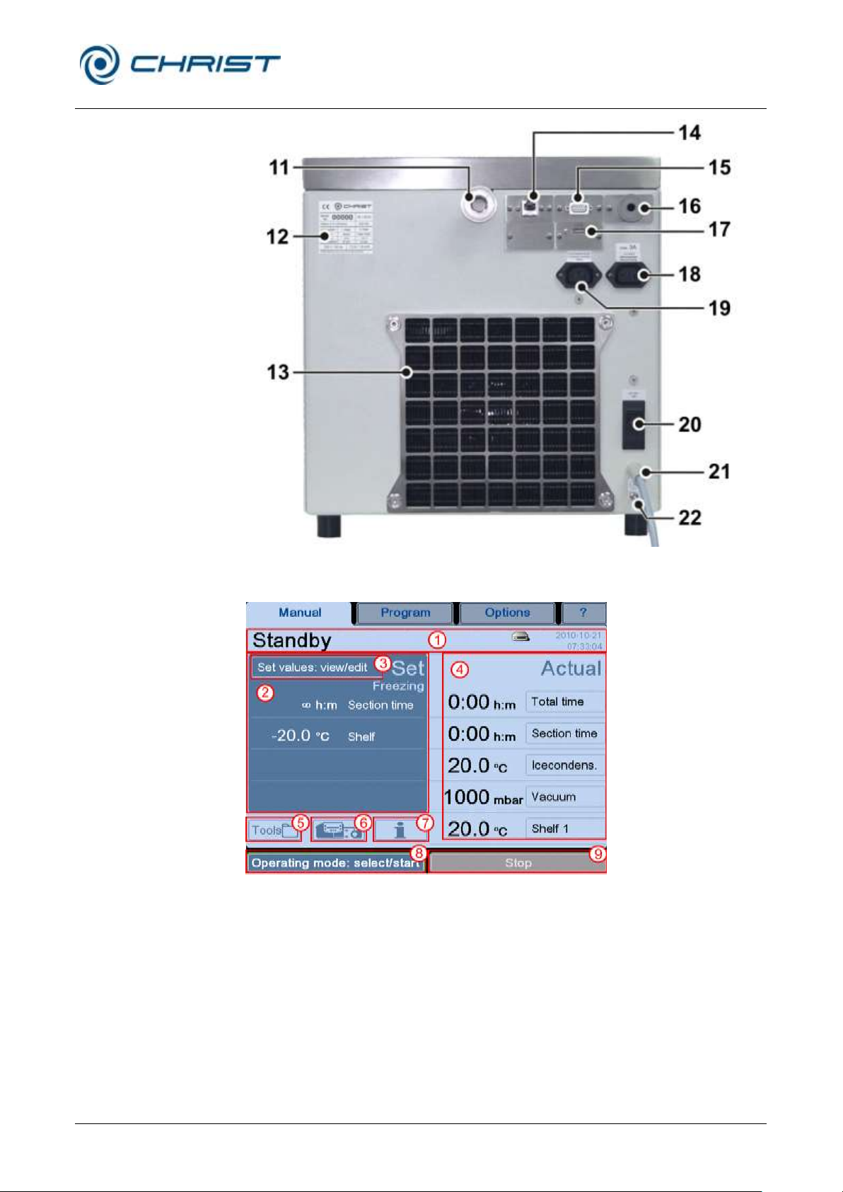
Freeze-dryer Alpha 1-4 LSCplus
Freeze-dryer Alpha 2-4 LSCplus
11 Appendix
Version 01/2011, Rev. 2.3 of 03/07/2017 • sb
99 / 131
Translation of the original operating manual
11 Vacuum connection
12 Name plate
13 Heat exchanger of the
refrigeration unit
14 Data interface
15 Electrical connection of
the vacuum sensor
16 Connection of the
vacuum sensor
17 Option: USB port
18 Power supply of the
vacuum pump
19 Power supply of the
pressure control valve
20 Mains fuse
21 Mains cable
22 Equipotential bonding
screw
1 Status line
2 Set process values
3 Button "Set values:
view/edit"
4 Actual values of the
current process
5 Button "Tools"
6 Button "Schematic
system diagram"
7 Button "Process and
equipment messages"
8 Button "Operating
mode: select/start"
9 Button "Stop"
Fig. 79: Rear view of the freeze-dryer
Fig. 80: LSCplus user interface
Page 100

Freeze-dryer Alpha 1-4 LSCplus
Freeze-dryer Alpha 2-4 LSCplus
11 Appendix
100 / 131
Version 01/2011, Rev. 2.3 of 03/07/2017 • sb
Translation of the original operating manual
NOTE
Ensure that the layer thickness of 1 to 2 cm is not exceeded, since
otherwise the drying time needs to be extended.
NOTE
Recommendation: Store the product vessels on the aluminium shelves or,
if possible, the entire rack with the shelves in the deep- freeze. The
advantage is that due to the higher cold storage capacity of the aluminium
material, the product will remain frozen for a longer period of time so that
the sample will not thaw.
NOTE
The vacuum pump always runs with maximum power. With this type of
freeze-dryer, the power of the vacuum pump cannot be controlled.
Step-by-step instructions – shelf drying
1 Freeze the sample separately, e.g. in a deep-freeze.
2 Check the ice condenser chamber and ensure that it is completely free
from water residues.
3 Close the media drain valve and install the base plate.
4 Switch the unit on 20 to 30 minutes prior to the start of the drying
process in order to let the vacuum pump warm up.
5 Place the plate rack on the base plate.
6 Transport the frozen samples as quickly as possible from the deep-
freeze to the freeze-dryer and place them on the shelves.
7 Install the drying chamber. Prior to doing so, check whether the O-ring
is completely free of dirt particles. The ground-in stopper of the acrylic
glass bell must be greased with high-vacuum grease.
8 Ensure that all of the valves of the acrylic glass bell are closed.
9 Ensure that the aeration valve is closed.
10 Ensure that the media drain valve is closed.
11 Start the main drying process either by opening the manual shut-off
valve or by waiting for the electromagnetic valve to open. Vacuum is
applied to the chamber and the freeze-drying process commences.
12 The operating panel displays the vacuum, the ice condenser
temperature, and the current operating mode.
13 The end of the process is reached when the ice condenser is no longer
loaded and when it again reaches a final temperature of approximately -
50°C to -54°C. The pressure decreases as a function of the ice
condenser temperature.
14 Switch the vacuum pump off and aerate the drying chamber via the
media drain valve or via a rubber valve.
15 Switch the unit off by actuating the mains power switch and take the
product out of the freeze-dryer.
 Loading...