

Page 1
Congrat ulation s! You have just
purchased what many people regard
as the finest headset in the world.
Since 1976 Chris King has been
supplying cyclists with the best made,
most reliable headsets you can buy.
With proper installation and maintenance you can expect to enjoy the
many years of the legendary quality
and performance built into each and
every component we make.
Installation
Headset insta llation requires specializ ed
too ls. We re comm end the p roce dure
be performe d by a professi onal bicycle
mechanic.
To ensure proper installation, the use of
headset cup press adapter kits are recommended. Our press adapters help to correctly align the bearing cups with the head
tube and prevent damage to the bearings
by directing pressure only and evenly over
the bearing cups. The baseplate installation
adapter prevents damage to the baseplate
by protecting the conical bearing contact
surface from the crown race setting tool.
Sizes are available to fit all popular headset
pressing and setting tools.
Preparation of Head Tube and
Installation of Bearing Cups
Pro per prep arat ion of the h ead
tube is e ssential for best headset
performance.
Ream and face the head tube to
ensure that the ends are square
and parallel to each other, and the
head tube bo re (inne r diamet er)
is corr ect (see tab le b elow) to
ensure proper press fit. Minimum
ream depth is 25. 4mm in to the
head tube.
Using a small file or sand paper,
carefully remove any sharp edges
or burr s an d sl ightly rou nd, or
chamfer, the inside edges of the
head tu be at the top and bottom
to prevent shearing any metal from
the cups during installation.
Cl ean t o rem ove a ny c hip s,
shavings, and/or cutting oil.
The prope r pre ss f it sh ould be
with no more tha n .1mm (.0 04”)
of interfere nce. See t able be low
for head t ube bore specifications.
Do not fil e or o therwise remove
materi al from the cup s to m ake
them fit.
Press in both bearing cups using
a he adset cup installa tion press
fitted wit h our headset cup press
adapters. Check to assure the cups
are seated flatly against the ends of
the head tube.
Preparation of Fork and
Installation of Baseplate
Prope r pr eparatio n of the fork is
essenti al for best headse t perfo rmance.
Ream and face the crown race seat
to ensure that the crown race seat
face is square with the steer tube.
See table above for cr own se at
outer diameter (OD) specifications.
The proper base plate press fit
should be with no more than .1mm
(.004”) of interference.
Cl ean t o rem ove a ny c hip s,
shavings, and/or cutting oil.
Slide the basepl ate, conica l side
up, o nto the steer tube. With the
bev eled sid e o f t he b asep late
inst allati on ad apter again st th e
baseplate, use a crown race setting
tool to set the baseplate.
Cutting of Steer Tube
Use extreme caution when cu tting
steer tube to avoid injury.
Insert fork into frame.
Remove O-ring from bearing cap
and slide b earing c ap, then any
spacers and the stem over steer
tube. Scribe a line flus h with t op
of stem.
Remove ste m and mark another
line 3mm below the first . Cut on
the lower line using a hack saw
and saw guide.
Remove all sharp edges from inside
and outside of steer tube. With a file
or sandpaper, round outside edge
of tube to avoid shearing the O-ring
upon installation.
Re-install O-ring into bearing cap
and apply grease to O-ring.
1.
2.
3.
4.
5.
1.
2.
3.
1.
2.
3.
4.
5.
NoThreadS et™
A.
G.
F.
E.
D.
C.
B.
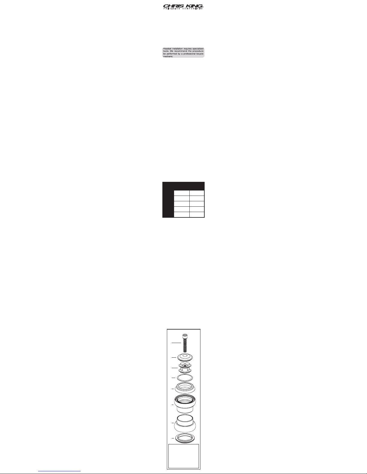
A. stem c ap screw
B. stem ca p
C. star nut
D. scuff w asher
E. bear ing cap
F. upper bear ing cup as sy.
G. lower be aring cu p assy.
H. basep late
H.
Head tube
bore (ID)
C r o w n
seat OD
1” 30.1 mm 26.5 mm
1” BMX
32.7 mm 26.5 mm
1-1/8” 33.9 mm 30.1 mm
1-1/4” 36.9 mm 33.1 mm
1.5 49.6 mm 39.8 mm
NoThreadset™
Page 2
Final Assembly and Adjustment
Insert fork into frame.
Taking care not to shea r O- ring,
slide bearing cap assy, then scuff
washer, spacers, and stem onto
steer tube. Tighten stem cap screw
to 6 to 15in.lbs. of torque.
Adj ust alig nmen t of st em a nd
se cu re ac co rd in g t o st em
manufacturer’s specifications.
Ch ec k h ea ds et fo r p ro pe r
ad ju st men t. W he n pr op erl y
ad jus ted , the fo rk wi ll rot ate
smoothly without play or restriction.
Some settling may occur after a few
rides; readjust if necessary.
New seals will produce some resistance in rotation for the first 50-100
hours of use. Avoid confusing this
with rubbin g or bindi ng th at ma y
result from improper installation or
stems that are not properly faced.
Installation of Star Nut
Thread star nut onto installation tool.
(If installati on tool is not a vailable,
thread bolt well into star nut and
use it to drive the star nut 15mm
below the top of the steer.)
With a soft hammer or mallet, drive
star nut straight into steer tube until
tool contacts top of steer tube.
Unscrew tool from star nut.
Maintenance
Chris King heads ets are designed
to provide the maximum life of any
headset with a minimum of maintenance. Besides an occasional adjustment, the only service necessary is
an occasional cleaning and regreasing of the bearings. Riding conditions
will dictate how often to service your
headset. In wet conditions, service
may be necessary as often as every
6 months; in dry conditions , up to
every 5 years.
Service of Bearings
Chris King sea led b earings have
removable snap rings that hold the
rubber seals in place.
Carefully, using a small screwdriver,
pick, or penknife, remove the snap
ring by insertin g tool in to split of
snap ring. Gently work one end of
the snap ring toward bearing center
until it is out of its groove. Follow the
ring around with the tool until the
snap ring is completely dislodged.
Lift and remov e exposed rubber
seal t o access t he interior of the
bearing.
Thoroughly flush the bearing with a
light spray lubricant (e.g., WD-40™)
and blow dry.
Some solvents, synthetic lubricants, and
grea ses with high- pressure ad ditives
may attack and damage seals and other
nonmetallic materials. Minimize exposure
to these substances and thoroughly dry
bearing assy after cleaning.
Lay a bead of waterproof g rease
aro und the top of th e be aring .
Rot ate the inn er race to wor k
grease throughout the ball area.
Wipe dirt an d other contaminants
from the seals and snap rings.
Replace rubber seal between inner
and outer bearing race.
Insert on e edge of sn ap ring into
groove of outer bearing race. Press
along entire groove until snap ring
is fully seated; a small gap should
be v isible be tween bot h ends of
the snap ring.
Turn inner race of bearing by hand
to tes t for binding . If bearing s do
no t run smo oth, rep eat ste ps
1-8. Bindi ng is often a res ult of
impro perly seated seals and/or
snap rings.
Used snap rings and seals can be reinstalled
unless warped, punctured, or otherwise dam-
aged. If dam aged, replace ment seals and
snap rings are available from any authorized
Chris King dealers or directly from Chris King
Precision Components.
Headset Removal
Rem ove cups from hea d tu be
with a s tandard cup removal tool,
taking care that tool cont acts the
inside edge s of the cup skirt, not
the bearing.
To rem ove bas eplate from fork,
we recom mend using a c rown
race rem oval t ool to lessen the
possibility of warping or deforming
the baseplate. If necessary, a 1/4”
or 3 /8” drif t punch can be used
instead. Be sure to alternate strikes
on eithe r sid e of fork crow n to
lessen the po ssibility of warpin g
or bending.
After removing the baseplate from the
fork, check for deformities by placing
it on a level surface. If the baseplate
does not sit level on the surface and
in any way appears to be warped or
deform ed, it must be replaced for
optimal bearing performance.
Baseplates and other headset parts
are available from any authorized
Chris King Dealer o r directly f rom
Chris King Precision Components by
calling our Customer Service number
at 800-523-6008.
Warranty
Chris King Precision Components warrants its bicycle headsets to be free from
defects in materials or workmanship for
a period of 10 years from the original
date of purchase. Any Chris King product that is found by Chris King Precision
Components to be defective in materials or workmanship will be repaired or
replaced at the sole discretion of Chris
King Precision Components providing it
is returned to the factory freight prepaid.
This warranty does not cover damage
or failure resulting from misuse, abuse,
alteration, neglect, normal and reasonable wear and tear, c rash or impact,
failure to perform routine maintenance
as instructed, or use other than that for
which the product was intended.
If a defect is found, our entire liability
and your sole remedy shall be, at our
option, free repair or replacement of the
Chris King product. Chris King Precision
Components shall not be held liable for
any indirect, special, or consequential
damages. The warranty does not cover
any Chris King Precision Components
product where the serial number has
been altered or removed. This written
express warranty is in lieu of all other
warranties, implied or expressed, and
does not cover any representation or
warranty made by dealers beyond the
provisions of this warranty. This warranty
gives you specific legal rights, and you
may also have other rights which vary
state to state.
Thank you for your purchase!
Made in the USA
All Chris King Precision Components
products are manufactured in the USA
using industry leading environmental
and quality control standards.
Printed with soy ink. Contains 100%
post-consumer recycled paper fiber.
Chris King Precision Components
2801 NW Nela Street
Portland, Oregon 97210
800.523.6008
www.chrisking.com
[email protected]
1.
2.
3.
4.
1.
2.
3.
1.
2.
3.
4.
5.
6.
7.
8.
1.
2.
3.
Rev. 1/09-
A
 Loading...