


52" TURBO® Fan with HYFLO® Door
Fan Type Fan Assembly
Part No.
Sub Assembly
Part No.
Bess Lab
Te st N o .
Voltage Hz Ph HP Fan
rpm
cfm @
.10" w.c.
cfm/Watt
.10" w.c.
Standard 49740-22* 49862-22 04334 230 60 1 1.5 564 24900 20.8
High Capacity 49740-21* 49862-21 04312 230 60 1 1.5 611 27700 18.3
Standard 49740-42* 49862-42 04335 208-230/460 60 3 1.5 566 24800 20.5
High Capacity 49740-41* 49862-41 04318 208-230/460 60 3 1.5 615 27900 18.2
High Capacity 49740-51* 49862-51 200-380/415 50 3 1.5
*Part Numbers shown are for White Fans with White Cones. Add a "B" to the Part Number example: "49740-22B" for a Black Fan w/ Black
Cone, Add a "BW" for a Black Fan w/ White Cone.
Installation & Operator’s Instruction Manual
MV1864PAugust 2017

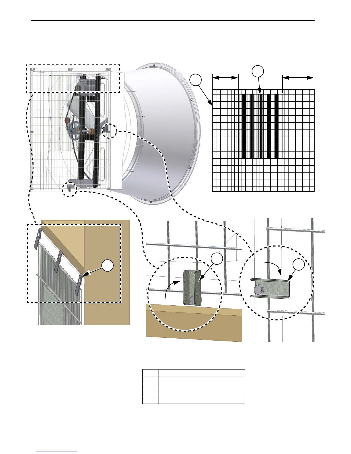
Fan and Fan Framing Dimensions
3
4
1
5
Item Description
1 59” [149.86 cm]
2 67.81" [172.2 cm]
3 53” [134.91 cm]
4 7.5" [19.1 cm]
5 59" [149.86 cm]
6 8.3 [21.11 cm]
6
Figure 1. Fan and Framing Dimensions
2
MT1864-036 2/05
Figure 2. Rough opening Spacing
2
2
1
Item Dimension
1 13" [33 cm] Min. for round Cones
2 56-1/2" [143.51 cm]
Fan and Fan Framing Dimensions
Planning the layout of the spacing between fans is very important. A Minimum of 13" between Fan rough openings
is required so the Cones do not interfere. Dimensions for rough openings for Fans are shown in Figure 2 below.
Important! The Fan Inlet and exhaust must be kept clear of obstructions. Failure to keep the Fan airflow path clear
of obstructions could cause loss of Fan perfomance and Fan damage.
Do Not operate these Fans with a variable speed control device. Operating static pressure should be less than 0.15
inches water column.
2
MV1864P

Installation
Mimimum 1/8" Tip
Clearance
Rotate Blade
Step 1: Set the Fan in the Framed
Opening. Rotate Fan Blade and
Check for 1/8" Blade Tip
Clearance
Note: Fan shown without components for clarity.
Fan Mounting
Insert the Fan Assembly in the wall opening. Rotate the Fan Blade by hand and check to make sure that
there is a minimum of 1/8" Blade clearance all the way around the Shroud orifice. Shift the Fan around in
the wall opening, if needed, to achieve at least 1/8" clearance all the way around. Now the Fan is ready to
be attached to the wall.
Installation
MV1864P
3

Installation
Figure 3. Installing Screen Clips
1
2
2
5
3
4
MV1864-006 1/05
Step 1: Fasten Fan to Wall at top (Use Screen
Step 2: Fasten Fan to Wall at Bottom
and sides (Use Screen Clips)
Key Description
1 Screen Retainer (Incl. in Parts Pkg.)
2 1/4 x 1-3/4 SS Lag Screw (Incl. in Parts Pkg.)
3 Screen Clip (Incl. in Parts Pkg.)
4 Nylon Washer (Incl. in Parts Pkg.)
5 Top Fan Shroud Flange
6 Post Bracket
Step 3: Fasten Fan to Wall at the
Post Brackets
2
6
Locate the three holes across the top Fan Shroud flange (Item 5, Figure 3). Line up the Screen Retainers
included in the Parts Package (Item 1, Figure 3) with these three holes, slip them over the top Fan Shroud
flange, and using (3) 1/4 x 1-3/4 Lag Screws included in the Parts Package attach the Fan to the Wall
(Step 1, Figure 3). In each of the remaining 5 holes in the Fan Shroud flange, use a 1/4 x 1-3/4 Lag Screw,
two Nylon Washers, and a Screen Clip, all included in the Parts Package, to secure Fan to the Wall as
shown below in Step 2. Only tighten the Lag Screws enough that the Clip will retain it’s position, but can
still be rotated by hand. Use two more Lag Screws to attach the Fan to the Wall through the holes in the
Post Brackets (Step 3, Item 6).
4
MV1864P

Installation
Key Description
1 Door Spring
2 Door
3 Bottom Pivot Bracket
4 Door Clip
5Washer
1
2
Pull the Door to Clear the Bottom Pivot Bracket
Step 1: Unhook the Door
Springs
3
2
Lift the Door up to Clear the Bottom
Pivot Bracket
Step 3: Lift up the Door
Step 4: Pull the Door out
Step 2: Remove Door Clip and Open the Doors
Figure 4. Removing the Doors
2
4
5
Remove and Discard
Remove and Discard
Removing the Doors
To avoid damaging the Fan Doors it is best to remove them before attaching the Cone. Unhook the Door Springs from the Door
and leave them attached to the Fan so they are not lost (Figure 4, Step 1). Remove the Door Clip and Washer and open up the
Doors (Step 2). You can discard the Door Clip and Washer. Lift one Door up so it will clear the Bottom Pivot Bracket (Step
3), and Pull the Door out (Step 4). Set the Door aside. Repeat the same process to remove the second Door.
MV1864P
5

Installation
Key Description
1 Cone
2 1/4-20 x .8 SS HH Bolt (Parts Pkg.)
3 1/4-20 HX Serrated Flange Nut (Parts Pkg.)
Figure 5. Attaching the Cone at the Top
Cutout in the bottom of Cone
extends to the edge
1
Cutout in the top of Cone does
not extend to the Cones edge
3
2
3
2
From insided of Fan push down on the Cone while
a second person pushes the Cone onto Shroud from the outside.
Figure 6. Sliding the Cone on at the Bottom
Key Description
1 Cone
2 Shroud
1
2
Attaching the Cone
To install the Cone you must first identify the Top of the Cone. The cutout in the top of the Cone does not extend
out to the Cones edge (See Figure 5). Begin Installing the Cone by hooking the top of the Cone over the top of the
Fan orifice. At this time only attach the Cone to the Shroud at the upper most two holes using (2) 1/4-20 Bolts and
(2) 1/4-20 Flange Nuts provided in the Parts Package (See Figure 5).
Slide the Remaining Cone over the Shroud orifice, working around the Cone from top to bottom. When you get to
the bottom of the Cone it is best to have a second person push down on the Cone from inside the Fan as you push
the Cone on. (See Figure 6 below).
6
MV1864P

Installation
3
Key Description
1 Cone
2 Shroud
3 1/4-20 x 7/8 SS HH Bolt
(Included in Parts Pkg.)
4 1/4-20 HX Serrated Flange Nut
(Included in Parts Pkg.)
Figure 7. Attaching Cone
4
1
2
3rd Hole
2nd Hole
Re-attach Spring to Door
in the 1st Hole
Key Description
1 Door Spring
2 Door
Figure 8. Re-attaching Door Spring
1
2
Finish attaching the Cone to the Fan Shroud with (4) 1/4-20 x 7/8 Bolts and Flange Nuts in the (4) remaining holes
pre-drilled in the Cone (Figure 7 below).
Replacing the Doors
Replace the Doors by reversing the steps used to remove them in the Removing the Doors section of this manual.
Important: Re-attach the Door Springs to the 1st Hole in the Doors (Figure 8). In windy conditions: If the Fan
Doors do not close when the Fan is off, or if the Doors open before the Fan turns on; increase the Spring tension by
re-attaching the Spring to the second or third hole in the Doors.
MV1864P
7

Installation
1
2
Step 1: Insert Cable into hole in the
Top Pivot Bracket
Step 2: Insert the Nylon Cable into
Cable Bracket. Leave approx.
1" extend past the Bracket.
Step 3: Attach Cable Bracket to Cone
with 1/4-20 Nut and Bolt
Figure 9. Attaching Nylon Cable
Item Description
1 Nylon Cable
2 Top Pivot Bracket Hole
3 Cable Bracket
4 Hole in Cone
5 1/4-20 Flange Bolt
6 1/4-20 Flange Nut
4
Approx. 1"
3
5
6
Attaching the Nylon Cable
Remove the Nylon Cable (Item 1, Step 1) from the parts package and insert it into the hole in the Top Pivot Bracket
(Item 2) as shown. Insert the other end of the Nylon Cable into the Cable Bracket (Item 3, Step 2) included in the
parts package leaving approximately 1" extend past the Bracket as shown. Attach the Cable Bracket to the hole at
the bottom of the Cone (Item 4) with a 1/4-20 Flange Bolt (Item 5) and Nut (Item 6) as shown in Step 3
8
MV1864P

Installation
2
1
Key Description
1 Cone
2 Grill End
Figure 10. Attaching Grill
Attaching the Grill
Attach the Grill to the Cone by inserting the Grill ends into the slots in the Cone as shown in Figure 10 below.
MV1864P
9
Installation
6-1/2 Spaces
8-1/2 Spaces
Proper Screen Orientation from Intake side of Fan
Intake side of Fan
Step 1: Slide Screen under Screen
Clips
Step 2: Rotate bottom
Screen Clip
Key Description
1Screen
2Insert Screen
3 Screen Retainer (Included in Parts Pkg.)
4 Screen Clip (Included in Parts Pkg.)
Figure 11. Attaching the Screen
Step 3: Rotate remaining
Screen Clips
4
4
3
1
2
Installing the Screen
Orient the Screen as shown below with the fine mesh section on the outside of the Fan. Slide the top of the Screen
under the Screen Retainers (Step 1, Figure 11) and turn the bottom Screen Clip to hold the Screen in place (Step
2). Turn the other (4) Screen Clips to secure the Screen in Place (Step 3).
10
MV1864P

Wiring
Figure 12. Wiring / Cord Routing
Drip Loop
Nylon Cord Retainer
and Lag Screw
Cut Screen to allow Cord exitUse Nylon Tie to attach Cord to Post
1. See Wiring diagram on Motor for Motor electrical connections. Follow local, state, and national electrical codes
for wiring
2. Install an electrical disconnect within reach of each Fan.
3. Route the motor cord (not supplied) toward the upper left corner of the Fan and attach the cord to the Motor Mount
using the Cable Tie—included in the hardware package. Leave a Drip Loop so that moisture collecting on the
Cord will not run down and damage the Motor (See Figure 12). Cut out a section of the Screen where you want
the Cord to exit the Fan, so that the Screen can be removed without the Cord getting in the way Figure 12). Use
the Nylon Cord Retainer and Lag Screw provided to secure the Cord to the Wall outside of the Fan. (Figure 12)
Wiring
MV1864P
11
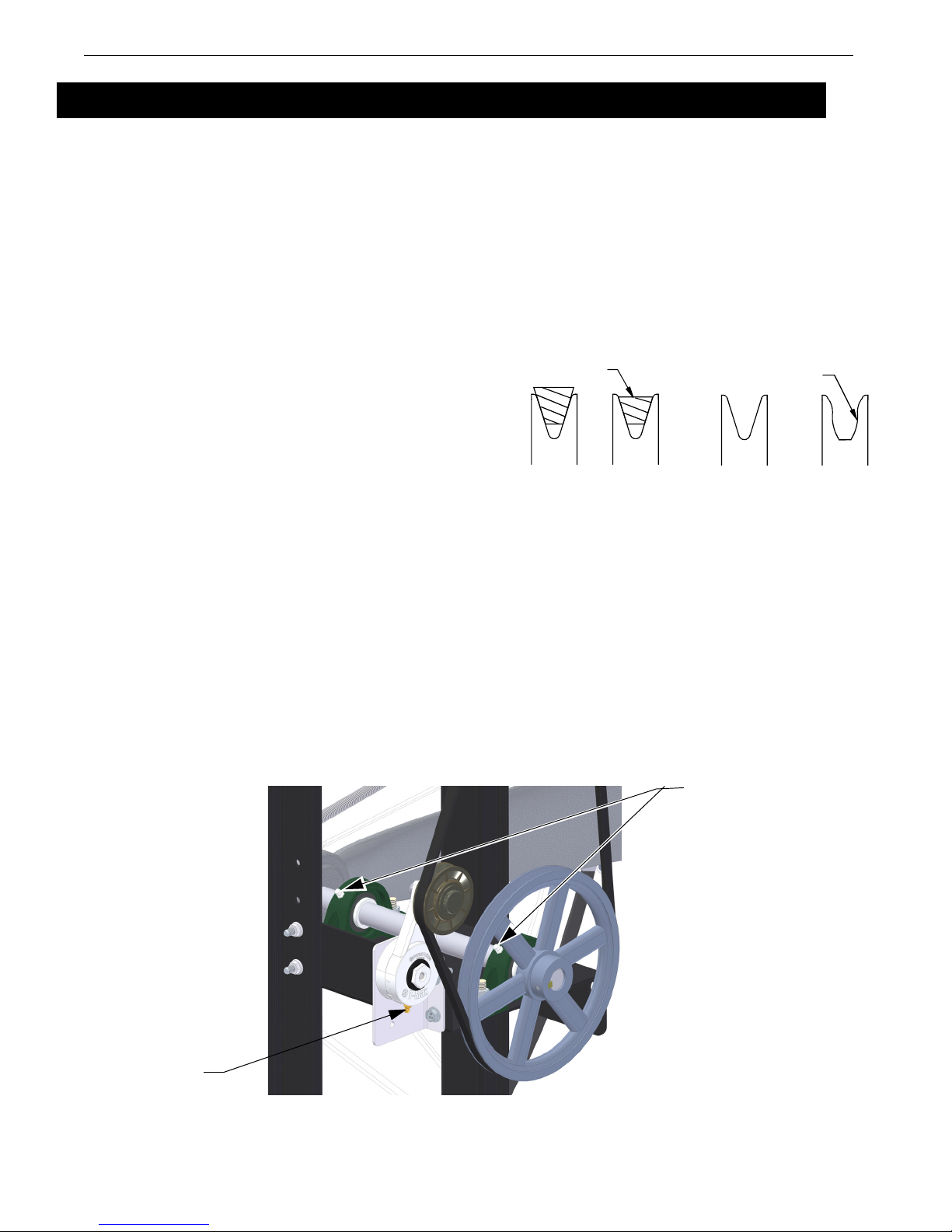
Maintenance
Worn Sheave
(Needs Replaced)
Good Belt Bad Belt
Good Sheave
Bad Sheave
MV1700-020 04/02
Bad Belt
(Needs Replaced)
Figure 13. Worn Sheave
Grease Zerk
Grease Zerk
Maintenance
•Disconnect Power Prior To Maintaining Or Cleaning The Fan. The fan may start automatically causing serious
injury or death.
• Service and repair of fans should be done only by a qualified technician.
• Keep the Fan clean for maximum life and best performance. Do Not spray water on Fan Shaft Bearings, Belt
Tensioner, or the Motor.
• Periodically check the V-Belt and replace if necessary. A bad Belt will cause a substantial drop in Fan performance or can break and cause Fan failure. If a Belt rides below the Sheave edge, replace the Belt. (See Figure 13)
• Keep HYFLO® Doors, Blades, and Housing clear of obstacles for best air performance.
•Check Sheaves for wear. Replace if Sheave
groove is worn.
(See Figure 13 to the Right).
Fan Bearing and Belt Tensioner
Lubrication
• Grease zerks are provided for lubrication on the fan shaft bearings and the belt tensioner.
• Lubricate the fan every 2-6 months or whenever these components get wet.
• Disconnect power to the fan before lubricating.
• Clean the zerk before lubricating to prevent contamination from entering the bearing.
• Use a high quality lithium based, NLGI #2, grease such as Shell Gadus S2 V100 2. Do not use incompatible greases
containing aluminum, barium, calcium, bentonite clay or polyurea thickeners.
• Slowly rotate the fan shaft by hand while slowly applying the grease. Rapidly applying grease to a stationary bearing
can damage the bearing seals.
• Apply about .10 oz (2.8 g, 3.1 cc) of grease at a time or until a slight amount of grease can be seen purging from the
seal.
12
MV1864P
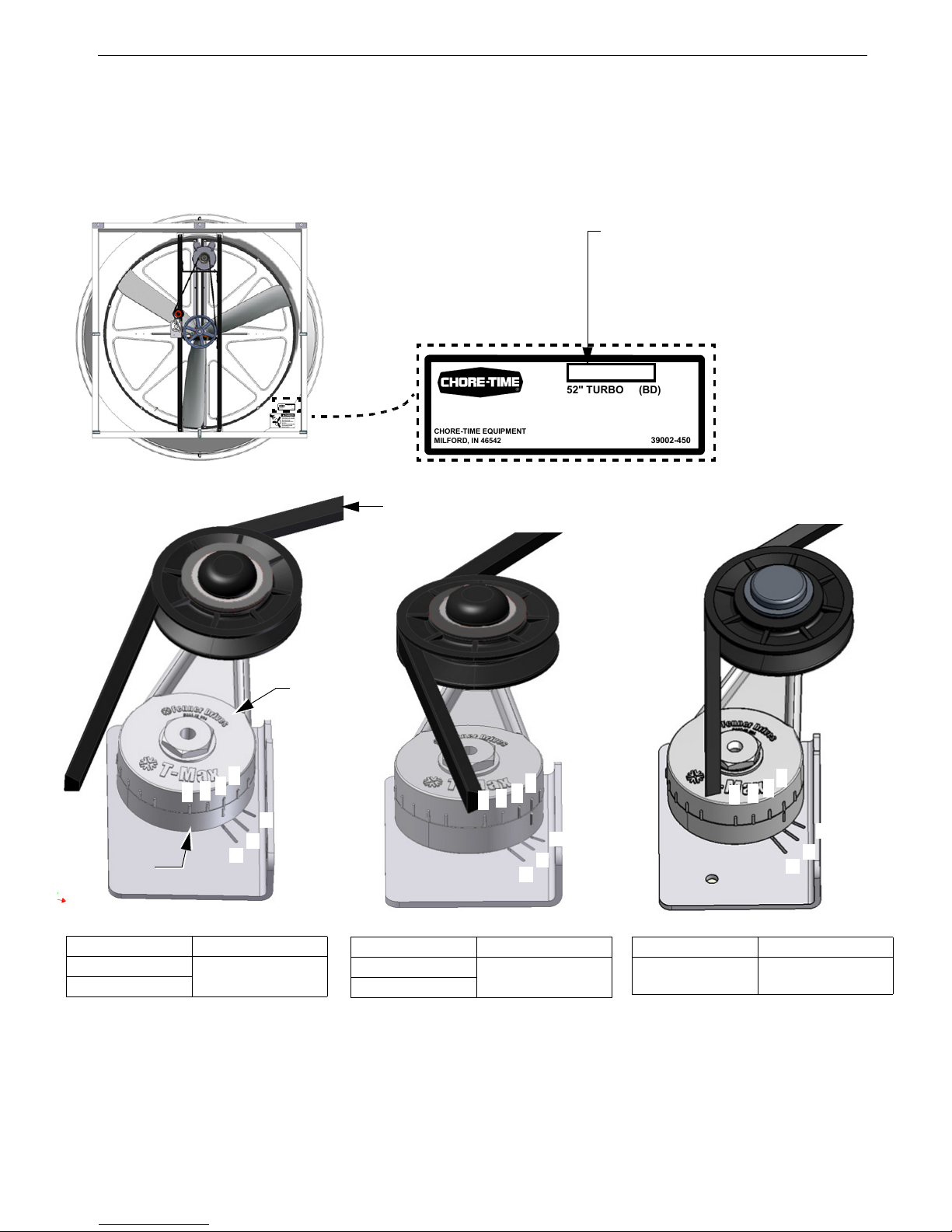
Maintenance
Note:
52" TURBO (BD)
39002-450
CHORE-TIME EQUIPMENT
MILFORD, IN 46542
49862-42
208-230/460 V, 60 HZ, 3PH, 1.5 HP
®
Fan Model Number
(see chart for correct Tensioner
positioning with newbelt installed)
Fan Part No. Tensioner Position
49862-22 Series 3rd Notch
"A" etched mark
49862-42 Series
2
1
3
4
2
1
3
4
Figure 14. Tensioner position
52" TURBO (BD)
39002-450
CHORE-TIME EQUIPMENT
MILFORD, IN 46542
49862-42
208-230/460 V, 60 HZ, 3PH, 1.5 HP
®
A
B
C
A
B
C
A
B
C
2
1
3
4
Fan Part No. Tensioner Position
49862-21 Series 4th Notch
"C" etched mark
49862-41 Series
Fan Part No. Tensioner Position
49862-51 Series 4th Notch
"B" etched mark
Outside Wheel
Inside Wheel
Belt
Belt Tensioner Position
When the Belt is installed the Tensioner will rotate to a set position. The notches on the outside wheel of the
Tensioner should line up with the etched mark (A,B, or C per chart) on the inside wheel of the Tensioner based on
the chart below.
When a Belt is worn the Tensioner position may vary as much as 1 full notch from new.
MV1864P
13

Part Numbers
14
MV1864P
Part Numbers
52" TURBO
39002-452
CHORE-TIME EQUIPMENT
MILFORD, IN 46542
49862-41
200-230/460 V, 60 HZ, 3 PH, 1.5 HP
®
HYFLO
®
Fan Part No.
52" TURBO
39002-452
CHORE-TIME EQUIPMENT
MILFORD, IN 46542
49862-41
200-230/460 V, 60 HZ, 3 PH, 1.5 HP
®
HYFLO
®
See Detail
Next Page

Part Numbers
MV1864P
15
Itemized Part Numbers
33
35
34
36
52" TURBO® Fan with HYFLO® Door 49862-XX (Sub Assembly) See page 1 for ordered Fan Part Number
Item Part Description Part No. Models-XX Item Part Description Part No. Models-XX
1 Motor, 3ph, 1.5hp, 60-230V 48608 -42,-41,-51,-51B 20 Cone (White) 49686 See Page 1
Motor, 1ph, 1.5hp, 60-230V 50496 -22,-21 Cone (Black) 49686B See Page 1
2 Sheave, 3" Motor (AK30) 8773 All 21 Cable Assembly 50618-1 All
Pulley, 3.45" Driven (AK34) 37919 -51,-51B 22 Pivot Bracket 49750 All
3 Sheave, 8.25" Driven (AK84) 28143 -21,-41 23 Pivot Support 49751 All
Sheave, 9.25" Driven (AK94) 40274 -22,-42 24 Door Spring Support 49799 All
Sheave, 7.75" Driven (AK79) 41989 -51,-51B 25 Clip, 2.00 x .7 SS 36729 All
4 V-Belt (AX59) 48615 -21,-41 26 Lag Screw 1/4-10 x 1.5" 41561 All
V-Belt (AX60) 48430 -22,-42 27 Nylon Washer 4856 All
V-Belt (AX58) 46676 -51,-52 28 Screen Retainer 49908 All
5 Shroud, 52" (White Interior) 55204* -22,-21,-42,-41,-51 29 Bolt, 1/4-20 x .8 HH 4404-17 All
Shroud, 52" (Black Interior) 55204B* -21B,-22B,-41B,-42B,-51B 30 Nut, 1/4-20 HX FLG Ser. 46298 All
6 Blade, Cast Aluminum w/ Bushing 49731 All 31 52" Post Support 50122 All
7 Motor Support 49734 All 32 Cable Assembly Bracket 50622 All
8 Bearing, 1" Pillow Block 50553 All 33 RPM Sensor Cord Assembly 46111 -41BS,-41S
9 Shaft, 1" dia. x 15.75" SS 49822 All 34 Nylon 1/4-28 x .50 Sensor Bolt 46134 -41BS,-41S
10 Bearing Support 49735 All 35 Steel Sensor Collar Half 46135 -41BS,-41S
11 Fan Post 49733 All 36 Nylon Sensor Collar Half 46136 -41BS,-41S
12
Screen, 52" HYFLO
®
TURBO® Fan
50049 All 37 Idler with Bushings (For Repair) 50879 All
13
Door Assembly (White) 49767 -21,-22,-41,-42,-51 38 1/8" Pop Rivet 50461 All
Door Assembly (Black) 49767B -21B,-22B,-41B,-42B,-51B 39 .125 x .50 Magnet 48427 All
14 Tensioner Assembly 48429 All 40 3/16" x 3/8" Pop Rivet 49869 All
15
Tensioner Support 49737 All 41 .192 x .55 Washer 50231 All
16 Magnet Stop Bracket 49738 All 42 5/16-18 x 1 SS Shoulder Bolt 54287All
17 Fan Post Brace 49900 All 43 5/16-18 SS Ser. Flange Nut 46764 All
18 Grill 49693 All 44 3/8-16 x 1.5 SS Bolt 4413-10 All
19 Spring, .055 x .50 O.D. x 11" 49629 All 45 3/8-16 SS Ser. Fl. Nut 50191 All
*Includes items 16,40 and 41
40
16
38
39
Magnet and Magnet Stop Bracket Detail
41
RPM Sensor Detail

Part Numbers
This Page left blank intentionally.....
16
MV1864P

Limited Warranty
Component Part Extended Warranty Period
TURBO® Fan fiberglass housings and cast aluminum blades
For as long as the original
purchaser owns the product.
TURBO
®
Fan motors and bearings
Two years from date of
installation.
TURBO
®
Fan components, including plastic shutters, fiberglass doors, and
polyethylene cones
Three years from date of
installation.
Limited Warranty
Chore-Time Group, a division of CTB, Inc. (“Chore-Time”) warrants new CHORE-TIME Turbo® Fans manufactured by
Chore-Time to be free from defects in material or workmanship under normal usage and conditions, for One (1) year from the
date of installation by the original purchaser (“Warranty”). Chore-Time provides for an extension of the aforementioned
Warranty period (“Extended Warranty Period”) with respect to certain Product parts (“Component Part”) as set forth in the table
below. If such a defect is determined by Chore-Time to exist within the applicable period, Chore-Time will, at its option, (a)
re pair t he Pro duct or Compo nent Part fre e of ch arge, F .O.B. the factory of manufacture or (b) replace the Product or Component
Part free of charge, F.O.B. the factory of manufacture. This Warranty is not transferable, and applies only to the original
purchaser of the Product.
CONDITIONS AND LIMITATIONS
THIS WARRANTY CONSTITUTES CHORE-TIME’S ENTIRE AND SOLE WARRANTY AND CHORE-TIME
EXPRESSLY DISCLAIMS ANY AND ALL OTHER WARRANTIES, INCLUDING, BUT NOT LIMITED TO, EXPRESS
AND IMPLIED WARRANTIES, INCLUDING, WIHTOUT LIMITATION, WARRANTIES AS TO
MERCHANTABILITY OR FITNESS FOR PARTICULAR PURPOSES. CHORE-TIME shall not be liable for any direct,
indirect, incidental, consequential or special damages which any purchaser may suffer or claim to suffer as a result of any
defect in the Product. Consequential or Special Damages as used herein include, but are not limited to, lost or damaged
products or goods, costs of transportation, lost sales, lost orders, lost income, increased overhead, labor and incidental costs,
and operational inefficiencies. Some jurisdictions prohibit limitations on implied warranties and/or the exclusion or limitation
of such damages, so these limitations and exclusions may not apply to you. This warranty gives the original purchaser specific
legal rights. You may also have other rights based upon your specific jurisdiction.
Compliance with federal, state and local rules which apply to the location, installation and use of the Product are the
responsibility of the original purchaser, and CHORE-TIME shall not be liable for any damages which may result from noncompliance with such rules.
The following circumstances shall render this Warranty void:
· Modifications made to the Product not specifically delineated in the Product manual.
· Product not installed and/or operated in accordance with the instructions published by the CHORE-TIME.
· All components of the Product are not original equipment supplied by CHORE-TIME.
· Product was not purchased from and/or installed by a CHORE-TIME authorized distributor or certified
representative.
· Product experienced malfunction or failure resulting from misuse, abuse, mismanagement, negligence, alteration,
accident, or lack of proper maintenance, or from lightning strikes, electrical power surges or interruption of
electricity.
· Product experienced corrosion, material deterioration and/or equipment malfunction caused by or consistent with the
application of chemicals, minerals, sediments or other foreign elements.
· Product was used for any purpose other than for the care of poultry and livestock.
·
The Warranty and Extended Warranty may only be modified in writing by an officer of CHORE-TIME. CHORE-TIME shall
have no obligation or responsibility for any representations or warranties made by or on behalf of any distributor, dealer, agent
or certified representative.
Chore-Time Group. A division of CTB, Inc.
PO Box 2000
MV1864P
Milford, Indiana 46542-2000 USA
Phone (574) 658-4101 Fax (877) 730-8825
E-mail: www.choretimepoultry.com
Internet: poultry@choretime.com
17

Safety Information
Safety Information
DANGER : Electrical Hazard
Disconnect electrical power before inspecting or servicing equipment unless
maintenance instructions specifically state otherwise. Ground all electrical
equipment for safety. All electrical wiring must be done by a qualified electrician
in accordance with local and national electric codes. Ground all non-current
carrying metal parts to guard against electrical shock. With the exception of motor
overload protection, electrical disconnects and over current protection are not
supplied with the equipment.
DANGER : Rotating Fan Blade
Keep Hands away. Disconnect power before servicing. Fan may start
automatically. Do not operate the Fan without the screens in place.
Disreguard to the above mentioned Danger may cause serious injury including
death.
• Keep all Safety Signs and decals in good condition.
•Replace damaged or missing decals.
Note: The original, authoritative version of this manual is the [English] version produced by CTB, Inc. or any of its
subsidiaries or divisions, (hereafter collectively referred to as "CTB"). Subsequent changes to any manual made by
any third party have not been reviewed nor authenticated by CTB. Such changes may include, but are not limited
to, translation into languages other than [English], and additions to or deletions from the original content. CTB
disclaims responsibility for any and all damages, injuries, warranty claims and/or any other claims associated with
such changes, inasmuch as such changes result in content that is different from the authoritative CTB-published
[English] version of the manual. For current product installation and operation information, please contact the
customer service and/or technical service departments of the appropriate CTB subsidiary or division. Should you
observe any questionable content in any manual, please notify CTB immediately in writing to: CTB Legal
Department, P.O. Box 2000, Milford, IN 46542-2000 USA.
MADE TO WORK.
BUILT TO LAST.
Revisions to this Manual
Page No. Description of Change ECO
1 Added Bess Lab Test Numbers and Sub Assembly Part Numbers 33151
15 Added -51 models to Parts List
CTB, Inc.
PO Box 2000
Milford, Indiana 46542-2000 USA
Phone (574) 658-4101 Fax (877) 730-8825
E-mail: www.choretimepoultry.com
Internet: poultry@choretime.com
®
18
MV1864P
 Loading...