


Model 55,75,90, & HMC FLEX-AUGER
Installation and Operators Manual
Installation and Operators Manual
Contact your nearby Chore-Time distributor or representative for additional parts and information.
MA1702DAugust 2018

Limited Warranty Model 55,75,90, & HMC FLEX-AUGER
Limited Warranty
LIMITED WARRANTY
Chore-Time Group, a division of CTB, Inc. (“Chore-Time”) warrants the new CHORE-TIME FLEX-AUGER Model
55,75,90, & HMC equipment manufactured by Chore-Time to be free from defects in material or workmanship under
normal usage and conditions, for One (1) year from the date of installation by the original purchaser (“Warranty”). ChoreTime provides for an extension of the aforementioned Warranty period (“Extended Warranty Period”) with respect to
certain Product parts. If such a defect is determined by Chore-Time to exist within the applicable period, Chore-Time will, at
its option, (a) repair the Product or Component Part free of charge, F.O.B. the factory of manufacture or (b) replace the
Product or Component Part free of charge, F.O.B. the factory of manufacture. This Warranty is not transferable, and applies
only to the original purchaser of the Product.
CONDITIONS AND LIMITATIONS
THIS WARRANTY CONSTITUTES CHORE-TIME’S ENTIRE AND SOLE WARRANTY AND CHORE-TIME
EXPRESSLY DISCLAIMS ANY AND ALL OTHER WARRANTIES, INCLUDING, BUT NOT LIMITED TO,
EXPRESS AND IMPLIED WARRANTIES, INCLUDING, WIHTOUT LIMITATION, WARRANTIES AS TO
MERCHANTABILITY OR FITNESS FOR PARTICULAR PURPOSES. CHORE-TIME shall not be liable for any direct,
indirect, incidental, consequential or special damages which any purchaser may suffer or claim to suffer as a result of any
defect in the Product. Consequential or Special Damages as used herein include, but are not limited to, lost or damaged
products or goods, costs of transportation, lost sales, lost orders, lost income, increased overhead, labor and incidental costs,
and operational inefficiencies. Some jurisdictions prohibit limitations on implied warranties and/or the exclusion or
limitation of such damages, so these limitations and exclusions may not apply to yo u. This warranty gives the original
purchaser specific legal rights. You may also have other rights based upon your specific jurisdiction.
Compliance with federal, state and local rules which apply to the location, installation and use of the Product are the
responsibility of the original purchaser, and CHORE-TIME shall not be liable for any damages which may result from noncompliance with such rules.
The following circumstances shall render this Warranty void:
· Modifications made to the Product not specifically delineated in the Product manual.
· Product not installed and/or operated in accordance with the instructions published by the CHORE-TIME.
· All components of the Product are not original equipment supplied by CHORE-TIME.
· Product was not purchased from and/or installed by a CHORE-TIME authorized distributor or certified
representative.
· Product experienced malfunction or failure resulting from misuse, abuse, mismanagement, negligence, alteration,
accident, or lack of proper maintenance, or from lightning strikes, electrical power surges or interruption of
electricity.
· Product experienced corrosion, material deterioration and/or equipment malfunction caused by or consistent with
the application of chemicals, minerals, sediments or other foreign elements.
· Product was used for any purpose other than for the care of poultry and livestock.
·
The Warranty and Extended Warranty may only be modified in writing by an officer of CHORE-TIME. CHORE-TIME
shall have no obligation or responsibility for any representations or warranties made by or on behalf of any distributor,
dealer, agent or certified representative.
Effective: April 2014
2
MA1702D

Model 55,75,90, & HMC FLEX-AUGER Support Information
Fill in the following information about your FLEX-AUGER® Feed Delivery System. Keep this
manual in a clean, dry place for future reference.
Distributor’s Name_____________________________________________
Distributor’s Address___________________________________________
Distributor’s Phone______________________ Date of Purchase________
Installer’s Name_______________________________________________
Installer’s Address_____________________________________________
Installer’s Phone_____________________ Date of Installation_________
System Specifications ___________________________________________
Feed Delivery System Supplying __________________________________
Support Information
The Chore-Time FLEX-AUGER® Feed Delivery System is designed to convey poultry and livestock feed
types. Using this equipment for any other purpose or in a way not within the operating recommendations
specified in this manual will void the warranty and may cause personal injury and/or death.
This manual is designed to provide comprehensive planning, installation, wiring, operation, and parts listing
information. The Table of Contents provides a convenient overview of the information in this manual.
MA1702D
3

Contents
Topic Page
Limited Warranty. . . . . . . . . . . . . . . . . . . . . . . . . . . . . . . . . . . . . . . . . . . . . . . . . . . . . . . . . . . . . . . . 2
Support Information . . . . . . . . . . . . . . . . . . . . . . . . . . . . . . . . . . . . . . . . . . . . . . . . . . . . . . . . . . . . . 3
Safety and General Information . . . . . . . . . . . . . . . . . . . . . . . . . . . . . . . . . . . . . . . . . . . . . . . . . . . . 6
Follow Safety Instructions . . . . . . . . . . . . . . . . . . . . . . . . . . . . . . . . . . . . . . . . . . . . . . . . . . . . . . . . . . . . . . 6
Decal Descriptions . . . . . . . . . . . . . . . . . . . . . . . . . . . . . . . . . . . . . . . . . . . . . . . . . . . . . . . . . . . . . . . . . . . . 6
DANGER: Moving Auger . . . . . . . . . . . . . . . . . . . . . . . . . . . . . . . . . . . . . . . . . . . . . . . . . . . . . . . . . . 6
DANGER: Electrical Hazard . . . . . . . . . . . . . . . . . . . . . . . . . . . . . . . . . . . . . . . . . . . . . . . . . . . . . . . . 6
DANGER: Springing Auger . . . . . . . . . . . . . . . . . . . . . . . . . . . . . . . . . . . . . . . . . . . . . . . . . . . . . . . . . 6
General Information. . . . . . . . . . . . . . . . . . . . . . . . . . . . . . . . . . . . . . . . . . . . . . . . . . . . . . . . . . . . . . 7
Selecting the System. . . . . . . . . . . . . . . . . . . . . . . . . . . . . . . . . . . . . . . . . . . . . . . . . . . . . . . . . . . . . . . . . . . 7
System Comparison Chart . . . . . . . . . . . . . . . . . . . . . . . . . . . . . . . . . . . . . . . . . . . . . . . . . . . . . . . . . . . . . . 7
System Weight & Length Specifications . . . . . . . . . . . . . . . . . . . . . . . . . . . . . . . . . . . . . . . . . . . . . . . . . . . 8
Planning. . . . . . . . . . . . . . . . . . . . . . . . . . . . . . . . . . . . . . . . . . . . . . . . . . . . . . . . . . . . . . . . . . . . . . . . 9
Planning the System . . . . . . . . . . . . . . . . . . . . . . . . . . . . . . . . . . . . . . . . . . . . . . . . . . . . . . . . . . . . . . . . . . . 9
Installation. . . . . . . . . . . . . . . . . . . . . . . . . . . . . . . . . . . . . . . . . . . . . . . . . . . . . . . . . . . . . . . . . . . . . 10
Recommended Layouts. . . . . . . . . . . . . . . . . . . . . . . . . . . . . . . . . . . . . . . . . . . . . . . . . . . . . . . . . . . . . . . . .10
Not Recommended Layouts . . . . . . . . . . . . . . . . . . . . . . . . . . . . . . . . . . . . . . . . . . . . . . . . . . . . . . . . . . . . .10
Bin to Building Placement Chart . . . . . . . . . . . . . . . . . . . . . . . . . . . . . . . . . . . . . . . . . . . . . . . . . . . . . . . . . 11
Installation. . . . . . . . . . . . . . . . . . . . . . . . . . . . . . . . . . . . . . . . . . . . . . . . . . . . . . . . . . . . . . . . . . . . . 12
Installation Notes . . . . . . . . . . . . . . . . . . . . . . . . . . . . . . . . . . . . . . . . . . . . . . . . . . . . . . . . . . . . . . . . . . . . .12
Bin Location and Collar Information . . . . . . . . . . . . . . . . . . . . . . . . . . . . . . . . . . . . . . . . . . . . . . . . . . . . . .12
Boot Installation . . . . . . . . . . . . . . . . . . . . . . . . . . . . . . . . . . . . . . . . . . . . . . . . . . . . . . . . . . . . . . . . . . . . . .12
Auger Tube Installation . . . . . . . . . . . . . . . . . . . . . . . . . . . . . . . . . . . . . . . . . . . . . . . . . . . . . . . . . . . . . . . . 12
Supporting the System Inside the Building . . . . . . . . . . . . . . . . . . . . . . . . . . . . . . . . . . . . . . . . . . . . . . . . . 15
Supporting the System Outside the Building . . . . . . . . . . . . . . . . . . . . . . . . . . . . . . . . . . . . . . . . . . . . . . . .16
Elevated Systems. . . . . . . . . . . . . . . . . . . . . . . . . . . . . . . . . . . . . . . . . . . . . . . . . . . . . . . . . . . . . . . . . .16
Bin to Bin Fill Systems . . . . . . . . . . . . . . . . . . . . . . . . . . . . . . . . . . . . . . . . . . . . . . . . . . . . . . . . . . . . .16
Long Elevated Systems . . . . . . . . . . . . . . . . . . . . . . . . . . . . . . . . . . . . . . . . . . . . . . . . . . . . . . . . . . . . .17
Outlet Assembly Installation . . . . . . . . . . . . . . . . . . . . . . . . . . . . . . . . . . . . . . . . . . . . . . . . . . . . . . . . . . . .17
Control Unit & Power Unit Installation . . . . . . . . . . . . . . . . . . . . . . . . . . . . . . . . . . . . . . . . . . . . . . . . . . . . 20
Belt Drive Control Unit Installation . . . . . . . . . . . . . . . . . . . . . . . . . . . . . . . . . . . . . . . . . . . . . . . . . . . . . . .21
Auger Installation . . . . . . . . . . . . . . . . . . . . . . . . . . . . . . . . . . . . . . . . . . . . . . . . . . . . . . . . . . . . . . . . . . . . .22
Cover Plate Installation. . . . . . . . . . . . . . . . . . . . . . . . . . . . . . . . . . . . . . . . . . . . . . . . . . . . . . . . . . . . . . . . .24
Auger Brazing/Filing . . . . . . . . . . . . . . . . . . . . . . . . . . . . . . . . . . . . . . . . . . . . . . . . . . . . . . . . . . . . . . . . . .24
Restrictor Adjustment . . . . . . . . . . . . . . . . . . . . . . . . . . . . . . . . . . . . . . . . . . . . . . . . . . . . . . . . . . . . . . . . . .25
Straight-Through Tandem Boot . . . . . . . . . . . . . . . . . . . . . . . . . . . . . . . . . . . . . . . . . . . . . . . . . . . . . . . . . .26
Standard FLEX-AUGER Boots and Baffle Locations . . . . . . . . . . . . . . . . . . . . . . . . . . . . . . . . . . . . . . . . .27
Boot Baffles for Straight-Through Boot Systems. . . . . . . . . . . . . . . . . . . . . . . . . . . . . . . . . . . . . . . . . . . . .29
Feed Level Control Installation . . . . . . . . . . . . . . . . . . . . . . . . . . . . . . . . . . . . . . . . . . . . . . . . . . . . . . . . . .30
Hopper Level Control Switch (Single Phase) Wiring . . . . . . . . . . . . . . . . . . . . . . . . . . . . . . . . . . . . . .30
Hopper Level Control Switch (Three Phase) Wiring . . . . . . . . . . . . . . . . . . . . . . . . . . . . . . . . . . . . . .30
SENSOR PLUS™ Electronic Switch (Single Phase) Wiring . . . . . . . . . . . . . . . . . . . . . . . . . . . . . . . .31
Operation. . . . . . . . . . . . . . . . . . . . . . . . . . . . . . . . . . . . . . . . . . . . . . . . . . . . . . . . . . . . . . . . . . . . . . 32
Start-Up Procedure for New Systems. . . . . . . . . . . . . . . . . . . . . . . . . . . . . . . . . . . . . . . . . . . . . . . . . . . . . . 32
Parts Listing . . . . . . . . . . . . . . . . . . . . . . . . . . . . . . . . . . . . . . . . . . . . . . . . . . . . . . . . . . . . . . . . . . . 33
Model 55,75,90,& HMC Feed Delivery System Standard Components . . . . . . . . . . . . . . . . . . . . . . . . . . . 33
Steel Components . . . . . . . . . . . . . . . . . . . . . . . . . . . . . . . . . . . . . . . . . . . . . . . . . . . . . . . . . . . . . . . . . . . . .33
Power Unit Assembly Part Numbers . . . . . . . . . . . . . . . . . . . . . . . . . . . . . . . . . . . . . . . . . . . . . . . . . . . . . .34
MA1702D
4

Model 55,75,90, & HMC FLEX-AUGER
3259-0 Power Units . . . . . . . . . . . . . . . . . . . . . . . . . . . . . . . . . . . . . . . . . . . . . . . . . . . . . . . . . . . . . . . . . . . 35
Direct Drive Control Unit (Single Phase) . . . . . . . . . . . . . . . . . . . . . . . . . . . . . . . . . . . . . . . . . . . . . . . . . . 36
Stainless Steel Direct Drive Control Unit (Single Phase) . . . . . . . . . . . . . . . . . . . . . . . . . . . . . . . . . . . . . . 37
International Direct Drive Control Units (3 Phase) . . . . . . . . . . . . . . . . . . . . . . . . . . . . . . . . . . . . . . . . . . . 37
46051 Switch & Plate Assembly . . . . . . . . . . . . . . . . . . . . . . . . . . . . . . . . . . . . . . . . . . . . . . . . . . . . . . . . . 38
46051SS Switch & Plate Assembly . . . . . . . . . . . . . . . . . . . . . . . . . . . . . . . . . . . . . . . . . . . . . . . . . . . . . . . 38
Standard Belt Drive Control Units . . . . . . . . . . . . . . . . . . . . . . . . . . . . . . . . . . . . . . . . . . . . . . . . . . . . . . . . 40
24392-0 Contactor Box . . . . . . . . . . . . . . . . . . . . . . . . . . . . . . . . . . . . . . . . . . . . . . . . . . . . . . . . . . . . . . . . 42
Boot Components . . . . . . . . . . . . . . . . . . . . . . . . . . . . . . . . . . . . . . . . . . . . . . . . . . . . . . . . . . . . . . . . . . . . . 43
Model 55 Boot Components . . . . . . . . . . . . . . . . . . . . . . . . . . . . . . . . . . . . . . . . . . . . . . . . . . . . . . . . . 44
Model 75 Boot Components . . . . . . . . . . . . . . . . . . . . . . . . . . . . . . . . . . . . . . . . . . . . . . . . . . . . . . . . . 45
Model 75 Boot Components (continued) . . . . . . . . . . . . . . . . . . . . . . . . . . . . . . . . . . . . . . . . . . . . . . . 46
Model 90 Boot Components . . . . . . . . . . . . . . . . . . . . . . . . . . . . . . . . . . . . . . . . . . . . . . . . . . . . . . . . . 47
Model 90 Boot Components (continued) . . . . . . . . . . . . . . . . . . . . . . . . . . . . . . . . . . . . . . . . . . . . . . . 48
Model HMC Boot Components . . . . . . . . . . . . . . . . . . . . . . . . . . . . . . . . . . . . . . . . . . . . . . . . . . . . . . 49
Troubleshooting . . . . . . . . . . . . . . . . . . . . . . . . . . . . . . . . . . . . . . . . . . . . . . . . . . . . . . . . . . . . . . . . . 50
Maintenance . . . . . . . . . . . . . . . . . . . . . . . . . . . . . . . . . . . . . . . . . . . . . . . . . . . . . . . . . . . . . . . . . . . . 52
Livestock and Poultry Feed Consumption . . . . . . . . . . . . . . . . . . . . . . . . . . . . . . . . . . . . . . . . . . .53
MA1702D
5

Safety and General Information Model 55,75,90, & HMC FLEX-AUGER
Manboot 3/98
Safety and General Information
Caution, Warning and Danger Decals have been placed on the equipment to warn of potentially dangerous
situations. Care should be taken to keep this information intact and easy to read at all times. Replace missing or
damaged safety decals immediately.
Safety–Alert Symbol
This is a safety–alert symbol. Wh e n you see th i s symbol on y o ur equipm e nt, be aler t to the potential
for personal injury. This equipment is designed to be installed and operated as safely as
possible...however, hazards do exist.
Understanding Signal Words
Signal words are used in conjunction with the safety–alert symbol to identify the severity of the warning.
DANGER indicates an imminently hazardous situation which, if not avoided, WILL result in death or
serious injury.
WARNING indicates a potentially hazardous situation which, if not avoided, COULD result in death or
serious injury.
CAUTION indicates a hazardous situation which, if not avoided, MAY result in minor or moderate
injury.
Follow Safety Instructions
Carefully read all safety messages in this manual and on your equipment safety signs. Follow recommended
precautions and safe operating practices.
Keep safety signs in good condition. Replace missing or damaged safety signs.
Decal Descriptions
DANGER: Moving Auger
This decal is placed on the Clean-Out Cover of the FLEX-AUGER Control
Unit.
Severe personal injury will result, if the electrical power is not disconnected,
prior to servicing the equipment.
DANGER: Electrical Hazard
Disconnect electrical power before inspecting or servicing equipment unless
maintenance instructions specifically state otherwise.
Ground all electrical equipment for safety.
All electrical wiring must be done by a qualified electrician in accordance with local
and national electric codes.
Ground all non-current carrying metal parts to guard against electrical shock.
Electrical disconnects and over current protection are not supplied with the
equipment.
DANGER: Springing Auger
Use caution when working with the Auger--springing auger may cause
personal injury.
6
MA1702D

Model 55,75,90, & HMC FLEX-AUGER General Information
System Tube Dia. Delivery Feed Types Max. Part.
Rate* Size
Model 55 2-1/4” 15 lb/min. mash, crumbles 1/8” x 1/2”
(55 mm) (7 kg/min.) 18% moist. content (3 mm x 13 mm)
Model 75 3” 50 lb/min. mash, crumbles 1/8” x 1/2”
(75 mm) (22 kg/min.) 18% moist. content (3 mm x 13 mm)
Model 90 3-1/2” 100 lb/min. mash, pellets, 3/16” x 1/2”
(90 mm) (45 kg/min.) shelled corn (5 mm x 13 mm)
18% moist. content
Model HMC 3-1/2” 50 lb/min. high-moisture corn, 3/8” x 3/4”
(90 mm) (22 kg/min.) larger pellets,crumbles, (10 mm x 20 mm)
mash 27% moist. content
*Conveying capacity is based on feed with 40 pounds per cubic foot (640 kg. per cubic meter) density.
Conveying capacities for all the FLEX-AUGER Systems are determined using 348 RPM Power Units.
General Information
Selecting the System
CHORE-TIME Feed Delivery systems are designed to handle most common livestock and poultry feeds. We can
not guarantee satisfactory operation with all formulations. We suggest that you contact our Technical Service
Department concerning the use of new or unusual formulations.
FLEX-AUGER Feed Delivery Systems are the most versatile feed conveying systems available. Their ease of
installation, reliability, low maintenance, and adaptability for many different applications, make them an
indispensable part of any livestock feeding system.
The FLEX-AUGER Feed Delivery System you choose should be based on the following;
1.Particle Size - Feed particles that are too large for the system will cause damage to the particles, excessive
power requirements, and plugging of the system.
2.Moisture Content (18% maximum) - The moisture content of the feed, among other factors, determines the
amount of buildup that will occur on the auger and auger tubes when conveying feed. Feeds with high
moisture content (above 18%) will freeze if exposed to freezing temperatures. This type of feed tends to flow
less-easily causing higher power requirements. Feeds in High Moisture Corn applications should not exceed
27% moisture content.
3.Feed capacities - Each size of FLEX-AUGER delivers feed at a different rate. These rates should be matched
to your feed requirements. An application that requires a large volume of feed to be moved should use a
larger (i.e. Model 90 or HMC) auger system or possibly two smaller auger (i.e. Model 55 or 75) systems. See
below for System Comparison information.
4.Running Time - Size the system so that the maximum operating time is four hours per day (24 hours). If
necessary, refer to “Livestock and Poultry Feed Consumption” on page 53. If your system operating
times exceed four hours per day, contact your distributor or Chore-Time’s Technical Service Department.
NOTE: The maximum allowable liquid molasses content for all FLEX-AUGER Feed Delivery Systems is 2%.
At higher liquid molasses content or at moisture levels above the recommended limits, the auger tubes can become
coated. This reduces the carrying capacity of the feed delivery system, causing eventual plugging of the system.
Commercial layer applications require the use of all steel FLEX-AUGER Feed Delivery Systems. Hardened steel
elbows are required for these applications. This is due to the abrasive feed particles in commercial layer feed
rations. Do not mix steel and PVC components within a system.
System Comparison Chart
MA1702D
7

General Information Model 55,75,90, & HMC FLEX-AUGER
Model 55
Motor Maximum Maximum
H.P. Line Length Extension
1/3 150’ (46 M) 185’ (56 M)
1/2 250’ (76 M) 285’ (72 M)
Model 75
Motor Maximum Maximum
H.P. Line Length Extension
1/2 80’ (24 M) 125’ (38 M)
3/4 150’ (46 M) 185’ (56 M)
1 200’ (61 M) 245’ (75 M)
Model 90
Motor Maximum Maximum
H.P. Line Length Extension
1/2 30’ (9 M) 65’ (20 M)
3/4 90’ (27 M) 125’ (38 M)
1 150’ (46 M) 185’ (56 M)
Model HMC
Motor Maximum Maximum
H.P. Line Length Extension
1/2 30’ (9 M) 55’ (17 M)
3/4 90’ (27 M) 105’ (32 M)
1 150’ (46 M) 185’ (56 M)
System Weight & Length Specifications
Adequate support must be provided to prevent the tubes from sagging and support the weight of the Control Unit.
The auger, tubes, and feed weigh approximately 6 lbs/ft. (9 kg/m). The Control Unit weighs approximately 80 lbs.
(36 kg).
Line lengths specified allow for two 45 degree elbows in the elevation. Reduce line length by 30’ (9 m) for each
additional horizontal 90 degree elbow.
For Tandem Systems, raise the horsepower one size over recommendations in the table below or reduce line length
by 50’ (15.4 m).
Note: If voltage supplied is 208V, reduce the line lengths by 20%.
Horsepower requirements are based on length of the FLEX-AUGER System and type of system installed--number
of turns, tandem systems, etc. The charts included show maximum line lengths for FLEX-AUGER Systems plus
maximum lengths for systems using Extension Hoppers.
8
MA1702D

Model 55,75,90, & HMC FLEX-AUGER Planning
Planning
Planning the System
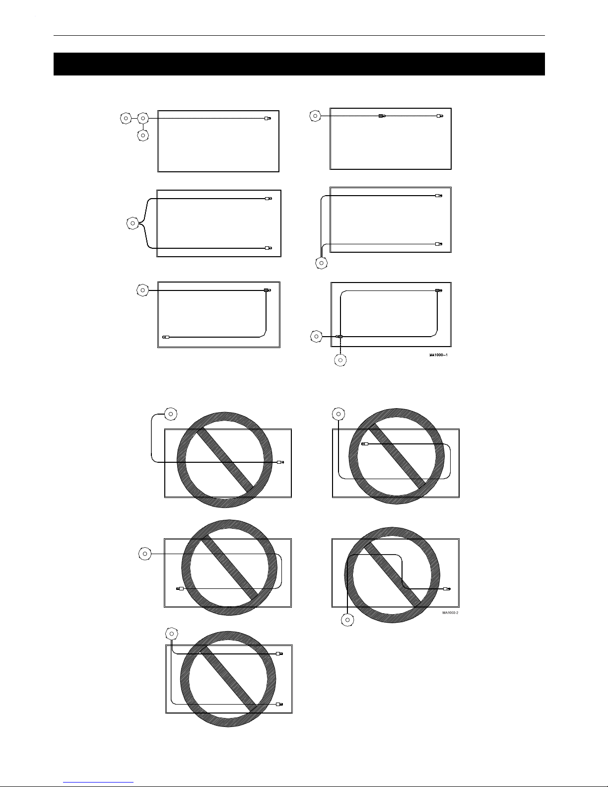
See Figure 1. on page 10 for recommended, and Figure 2. on page 10 for non-recommended FLEX-AUGER
installations. When laying out the FLEX-AUGER Feed Delivery System, plan the system so that the auger tubes
do not interfere with doors, windows, or other equipment.
See “Bin to Building Placement Chart” on page 11 for different elevations and boots.
1.For the easiest installation and most trouble-free operation, locate the feed bin in a direct line with the FLEXAUGER Feed Delivery System. The “Bin to Building Placement Chart” on page 11 also provides some
points of reference for bin placement according to the height at which the FLEX-AUGER tube enters the
building. Remember, these are only examples. The layouts can be modified by changing the elbows, the tube
sections, and/or the distance from the bin to the building.
Locate the bin so that the FLEX-AUGER Feed Delivery System does not have to convey feed at an angle of
more than 60 degrees from the horizontal to enter the building at the desired height. Chore-Time considers a
45 degree elevation to be standard--the lower the angle, the more reliable the system.
2.Lay out the system as straight as possible. Avoid extra elbows and curves by locating the feed bin in line with
the feeders. One horizontal 90 degree right hand turn is permissible inside the building. 180 degree turns are
not recommended under any conditions.
If additional turns or elbows are required, use extension hoppers. Remember: one 90 degree elbow requires
the same power as 30’ (9.1 m) of straight line.
3.Plan the system so that the auger tubes are directly over the feeders or hoppers to be filled as possible. The
drop tubes may be angled up to a maximum of 45 degrees from the vertical if necessary. At angles greater
than 45 degrees, bridging in the drop tubes may occur.
4.The control unit must be located over a feeder or hopper that will require as much or more feed than any of
the other feeders or hoppers. If frequent filling is desired, mount the drop tube switch or hopper level switch
low so that this feeder or hopper will have a low feed level. This causes the feeder to call for feed more often,
the system will restart, and the other feeders will be refilled sooner.
5.Do not locate outlet drops on or just before an elbow. Install the drop after the elbow so feed will cushion the
auger through the curve. If there is some reason why the outlet drop cannot be moved, it must have some
“feed bypass” to cushion the auger through the elbow.
6.Avoid horizontal left-hand turns if possible. The elbow in a left-hand turn is not cushioned by the feed and
will wear faster. On systems with a 90 degree horizontal left-hand turn, reduce the stretch to reduce wear.
NOTE: A rule of thumb for left-hand turns is to reduce stretch to 1" per 50’ (25 mm per 15.2 m) on
initial installation. Increase the stretch if necessary.
If an extension hopper is used:
A. Locate the hopper so there will not be any outlet drops on the short tube or elbow leading out of the hopper.
B. The longer portion of the system with most of the outlet drops should follow the extension hopper. For
example: in a 300’ (91.4 m) Model 75 System the distance from the bin to the extension hopper should
be 100’ (30.5 m). From the extension hopper to the control unit should be 200’ (61 m) with most outlets
placed on the 200’ (61 m) section. Refer to “System Weight & Length Specifications” on page 8, for
power unit requirements.
NOTE: The lower part of the extension hopper can be turned 90 degrees to the left or right in relation
to the top portion of the extension hopper. This allows the extension hopper to replace a
horizontal elbow where both might be located in approximately the same position in the system.
7.Remember the following points when installing a Straight-Through Tandem System or Two Motor Tandem
System:
A.The straight-through tandem bin arrangement uses one continuous auger.
B.The Two Motor Tandem bin arrangement uses two separate augers and power units.
C.Pour one level concrete pad for both bins (in either system).
D.Position bins so that legs will not interfere with the FLEX-AUGER System (in either system). See the
Two Motor Tandem System instructions (Model 75, 90, & HMC systems only).
8.See “System Weight & Length Specifications” on page 8 to determine maximum line lengths and power
unit requirements.
MA1702D
9
Installation Model 55,75,90, & HMC FLEX-AUGER
Figure 1.Recommended Layouts
Figure 2.Not Recommended Layouts
Installation
Recommended Layouts
Not Recommended Layouts
10
MA1702D

Model 55,75,90, & HMC FLEX-AUGER Installation
System Model Entrance Height 30 Degree Upper Bin Boot (part no. 4347) Straight-Out Upper Bin Boot (part no. 6093)
"H" 30 Degree 45 Degree 60 Degree 30 Degree 45 Degree 60 Degree
5’ (1.5 m) 9‘ (2.7 m) - - - - - - - - - - - - 11.5’ (3.5 m) 10’ (3 m) - - - - - -
6’ (1.8 m) 11’ (3.4 m) 8.5’ (2.6 m) 8’ (2.4 m) 13.5’ (4.1 m) 11’ (3.4 m) 10‘ (3 m)
Model 55, 75, 90, 7’ (2.1 m) 12.5’ (3.8 m) 9.5’ (2.9 m) 8.5’ (2.6 m) 15’ (4.6 m) 12’ (3.7 m) 11’ (3.4 m)
or HMC with 5’ 8’ (2.4 m) 14.5’ (4.4 m) 10.5’ (3.2 m) 9’ (2.7 m) 17’ (5.2 m) 13’ (4 m) 11.5’ (3.5 m)
radius elbows 9’ (2.7 m) 16’ (4.9 m) 11.5 (3.5 m) 9.5’ (2.9 m) 18.5’ (5.6 m) 14’ (4.3 m) 12’ (3.7 m)
10’ (3 m) 17.5’ (5.3 m) 12.5’ (3.8 m) 10 (3 m) 20’ (6.1 m) 15’ (4.6 m) 12.5’ (3.8 m)
11’ (3.3 m) 19.5’ (5.9 m) 13.5’ (4.1 m) 10.5’ (3.2 m) 22’ (6.7 m) 16’ (4.9 m) 13’ (4 m)
12’ (3.7 m) 21’ (6.4 m) 14.5’ (4.4 m) 11.5’ (3.5 m) 23.5’ (7.2 m) 17’ (5.2 m) 13.5’ (4.1 m)
13’ (4 m) 23’ (7 m) 15.5’ (4.7 m) 12’ (3.7 m) 25.5’ (7.8 m) 18’ (5.5 m) 14’ (4.3 m)
14’ (4.3 m) 24.5’ (7.5 m) 16.5’ (5 m) 12.5’ (3.8 m) 27’ (8.2 m) 19’ (5.8 m) 15’ (4.6 m)
15’ (4.6 m) 26.5’ (8.1 m) 17.5’ (5.3 m) 13’ (4 m) 29’ (8.8 m) 20’ (6 m) 15.5’ (4.7 m)
16’ (4.9 m) 28’ (8.5 m) 18.5’ (5.6 m) 13.5’ (4.1 m) 30.5’ (9.3 m) 21’ (6.4 m) 16’ (4.9 m)
17’ (5.2 m) 30’ (9.1 m) 19.5’ (5.9 m) 14’ (4.3 m) 32.5’ (9.9 m) 22’ (6.7 m) 16.5’ (5 m)
18’ (5.5 m) 31.5’ (9.6 m) 20.5’ (6.2 m) 14.5’ (4.4 m) 34’ (10.4 m) 23’ (7 m) 17’ (5.2 m)
19’ (5.8 m) 33.5’ (10.2 m) 21.5’ (6.5 m) 15.5’ (4.7 m) 36’ (11 m) 24’ (7.3 m) 17.5’ (5.3 m)
20’ (6.1 m) 35’ (10.7 m) 22.5’ (6.8 m) 16’ (4.9 m) 37.5’ (11.4 m) 25’ (7.6 m) 18.5’ (5.6 m)
Straight-out Boot
30° Boot
Bin to Building Placement Chart
Use this chart to determine the distance from building to center of bin ("X") at the various entrance heights ("H")
and degrees of elevations listed below.
•The bin on the right is shown with a straight-out bin boot.
•The bin on the left is shown with a 30 degree bin boot.
MA1702D
11
Installation Model 55,75,90, & HMC FLEX-AUGER
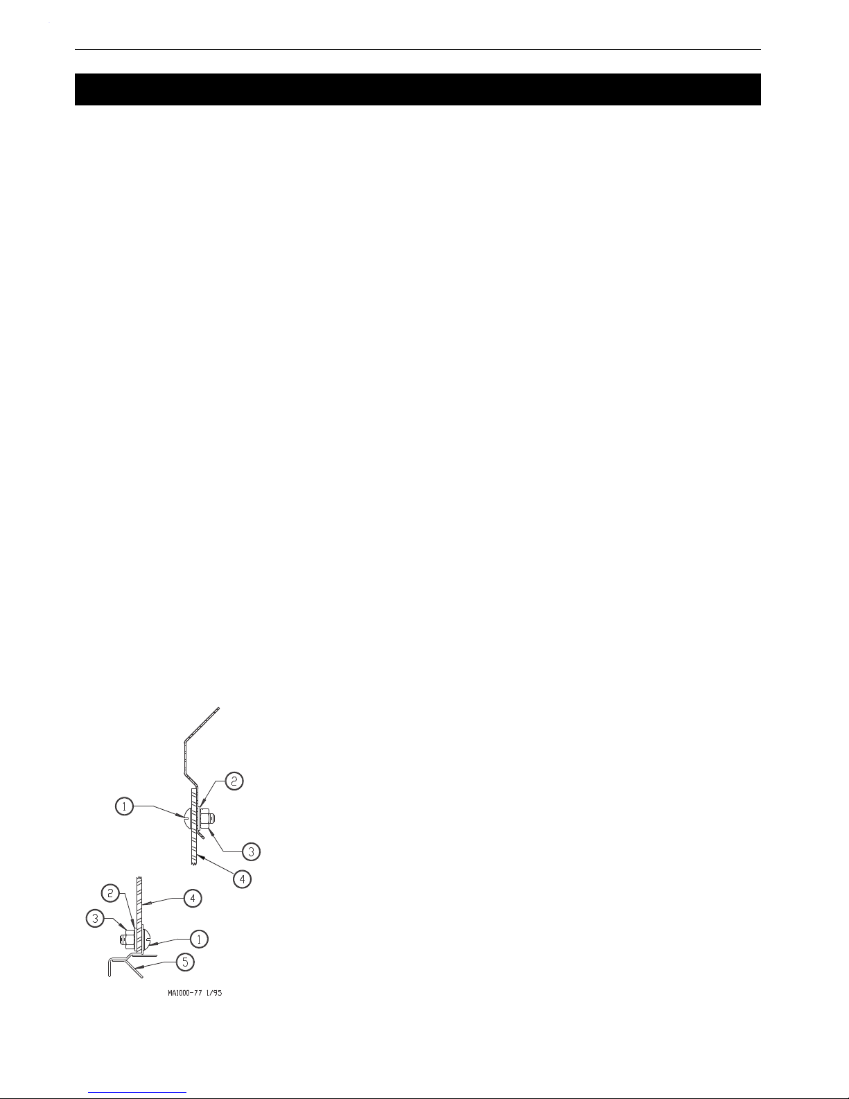
Key Description
1 5/16-18x3/4" Truss Head Screw
2 5/16" Nylon Washer
3 5/16-18 Nylon Hex Nut
4 Upper Boot Body
5 Transfer Plate
6 Welded Bin Collar
Figure 3.Boot Installation Diagram
Installation
Installation Notes
Install the equipment as specified in this manual. Failure to install as specified may cause damage to the equipment
and/or cause personal injury or death.
Take special notice of the warnings and safety decals on the equipment and in this manual.
Always wear protective clothing and protective glasses when working with the equipment.
Discarded materials, equipment, and boxes may be recycled. Recycle according to local and national codes.
Unless otherwise specified, the Model 55, 75, 90, & HMC Systems are installed similarly.
All the systems are available with straight-out or 30 degree upper boots, except the Model 55. The Model 55
requires the 30 degree upper boot (the straight-out boot is not available for the Model 55).
Bin Location and Collar Information
For easiest installation and trouble-free operation, locate the feed bin in a direct line with the FLEX-AUGER
System. The layout chart provides some points of reference for bin placement according to the height at which the
system enters the building.
The bin collar is installed during bulk bin assembly. Chore-Time bins have a welded collar. Bin Adapter Kits are
available to modify existing bins so that the welded collar can be used. In addition, most other feed bin
manufacturers have a collar available to be used with Chore-Time FLEX-AUGER Feed Delivery Systems.
Boot Installation
1.Insert the upper boot into the bin collar opening and turn it to line up with the direction that the auger line
will go. The boot must be as far up into the opening as it will go. Use the holes in the ring for drilling guides
and drill 11/32" (8.8 mm) holes in the upper rim of the boot. Attach the boot to the Bin Collar using the hardware provided. See Figure 3. for correct use of hardware to attach the boot.
IMPORTANT: Failure to install the hardware as shown in Figure 3 may cause breakage of the
Upper boot body.
2.Attach the transfer plate to the upper boot. Use truss head bin-seal bolts installed from the inside of the plate,
with flat washers placed under the nuts.
3. Insert the slide into the transfer plate slot so that it is in its operating position before bolting the slide shield in
place. Use two 5/16-18x3/4" hex head machine screws to secure the shield.
4.Bolt the lower boot to the transfer plate using four 5/16-18x3/4" hex head machine screws.
Auger Tube Installation
12
MA1702D

Model 55,75,90, & HMC FLEX-AUGER Installation
15 Degree Elbow .........16.5" or 419 mm
22.5 Degree Elbow ......24.75" or 628 mm
30 Degree Elbow .........33" or 838 mm
45 Degree Elbow .........49.5" or 1257 mm
These dimensions are measured along the
long, outside curve of the elbow. They do
not include the belled end of the elbow in
the measurement.
Figure 4.PVC Elbow Cutting Guidelines
Key Description
145° Elbow
2 Auger Tube
345° Elbow
4 Seal Ring
5 Neoprene Seal
6 Note: Belled end of elbows
and auger tubes should be
towards boot.
Figure 5.Elbow Installation outside the building
The FLEX-AUGER Delivery System includes two 45 degree elbows as standard equipment. These elbows are
used to make the sloping portion of the auger line at the feed bin, and elsewhere in the system if necessary. If
additional elbows are required, they should be ordered separately. Figure 4 shows how the elbow can be cut into
shorter sections.
1.Determine where the entrance hole for the auger tube must be located on the building and cut it.
2.Cut the elbow used where the auger enters the building (if necessary). Slide the seal ring and neoprene seal
over the straight end of the elbow and place it in the hole cut in the building, with the belled end outside the
building. (See Figure 5).
3.Model 75, 90, & HMC: Slide the belled end of the elbow or auger tube over the outlet end of the boot. A
clamp is provided to secure the elbow or auger tube to the boot.
Model 55: Install the Model 55 Stub Tube over the outlet end of the boot. A clamp is provided to secure the
Stub Tube to the boot.
Slide the belled end of the first elbow or auger tube over the stub tube.
4.Place the end of a straight section of tube inside the belled end of the elbow in the building. Hold the straight
section of auger tube so that it touches the elbow on the boot. Mark the spot where the tube aligns with the
"boot" elbow and cut the elbow at that point.
5.Place the belled end of the auger tube over the end of the elbow just cut, and hold the tube against the top
MA1702D
13

Installation Model 55,75,90, & HMC FLEX-AUGER
Direction of Travel
Key Description
1 Straight section of Auger
Tube
2 Belled end of Auger Tube
Figure 6.Proper Auger Tube Connection
elbow. Mark and cut the straight auger tube so that it will fit between the two elbows. Remember to cut the
auger tube long enough to fit inside the belled end of the elbow in the building. Figure 4 shows the direction
the auger is to run in relation to the belled end of the tube. NOTE: In some installations it may be possible to
eliminate the elbow on the boot, using only a straight auger tube and one elbow where the tube enters the
building.
6.Dry-fit all parts. When satisfied that elbows and tubes fit together smoothly, glue with PVC cement
according to the following instructions.
The auger tubes and elbows for the FLEX-AUGER systems are made of specially formulated PVC tubing.
Use the PVC solvent cement to make strong, reliable bonds.
FOLLOW DIRECTIONS ON THE CAN FOR SAFE HANDLING OF CEMENT.
1.Be sure tube is cut off squarely. Remove burrs from outside and inside the end of the tube.
2.Dry fit all parts. Tube should fit inside belled end of next tube to full depth without excess force.
3.Clean surfaces to be joined. SURFACES MUST BE FREE OF DIRT OR GREASE!
4.Apply a generous coat of cement to both the inside of the belled end and outside of the other tube. Be
sure cement covers all of the joint area so there are no bare spots.
5.Quickly join the tubes, giving them a twisting motion to bring them into alignment as they are joined.
6.Keep pressure on the joint until the PVC cement sets up.
ALL TUBE JOINTS EXPOSED TO MOISTURE AND WEATHER MUST BE SEALED OR
CAULKED TO WATERPROOF THEM IN ADDITION TO CEMENTING OR CLAMPING THE
JOINT!
7.If there is more than 15 feet (4.5 meters) of auger tube between the boot and the building, provide
additional support for the tubes so that the boot does not have to carry the weight of the auger. Extra
support can be achieved with cables or chains fastened to the bin legs and auger tube.
8.Install the remaining tubes in the system AFTER the outlet holes have been located and cut. The auger
tubes should be cemented using PVC cement supplied. NOTE: The tubes can be joined by cutting off
the belled ends and fastening tubes together with tube connectors if there is some reason why
permanent installation is not desired. (Tube Connectors are not standard equipment and must be
ordered separately for this type of installation).
14
MA1702D

Model 55,75,90, & HMC FLEX-AUGER Installation
Key Description
1 “S” Hook
2 Auger Tube
3 Chain
Figure 7.Proper Auger Tube Connection
Auger tube flattened
because the supports are
not high enough to keep
the weight of the auger
tube off the wall.
Auger tube pinched because
the Auger Tube is not in line
with the hole in the Wall.
Auger tube flattened because the
supports are not high enough to
keep the weight of the auger tube
off the wall.
Figure 8.Faulty Tube Installations
Supporting the System Inside the Building
Support the Auger Tubing with chain and "S" Hooks every 5 feet [1.5m]. Steel Tube systems require support every
10 feet [3m]. The system should be restrained from swinging by using chain and "S" hooks to brace the auger tube,
every 20 feet [6m], as shown in Figure 7.
Horizontal elbows need to be supported in at least two places. Chain, screw hooks, and "S" hooks are supplied as
a suspension kit for supporting the equipment. Keep the line as level and straight as possible.
If Drop Feeders, Extension Hoppers, Outlet Drops with long angled Drop Tubes, or other loads are imposed on
the system, extra support will be required.
Power Units require extra support to resist the twisting encountered when the motor starts and stops. Use the motor
mount base, all of the "ears" on the gearhead as well as the suspension point provided on the 46800 Control Unit
Box to support the Power Unit.
Adequate chain and "S" hooks are provided with each system to properly support it. Other means of supporting
the system are permissible as long as the system receives the correct support and the auger tube is not dented or
flattened. Alternative support systems must allow for expansion and contraction of the Auger Tubes.
When the auger tube passes through a side wall or partition, especially where it enters the building, the opening
should be made large enough so the auger tube can be supported without resting on the wall. If the auger tube rests
on the wall or partition, the auger tube may flatten out or become kinked--causing excessive wear. (See Figure 8).
MA1702D
15
Installation Model 55,75,90, & HMC FLEX-AUGER
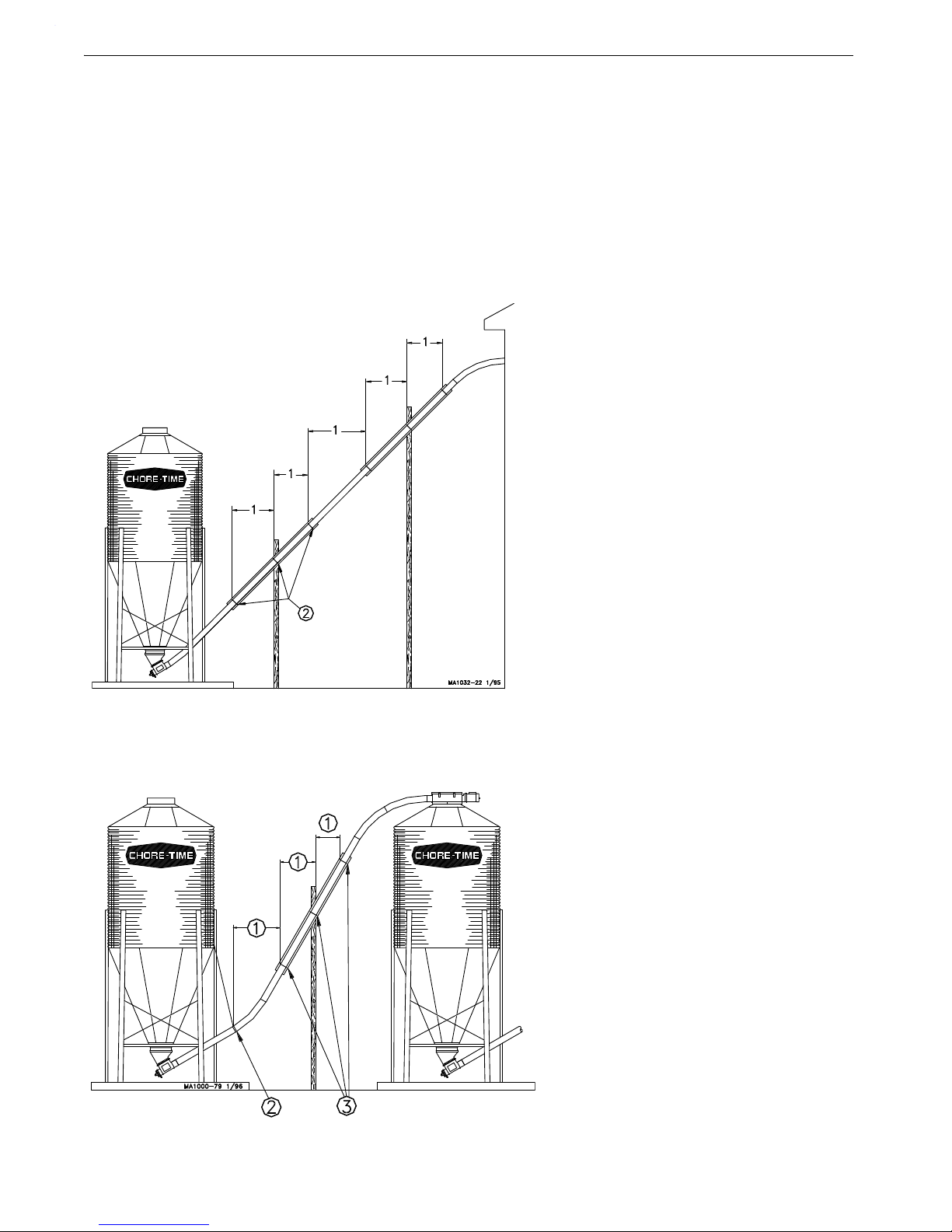
Key Description
1 5’ (1.5 m) for PVC systems
10’ (3 m) for STEEL systems
2 Place clamps here.
Figure 9.Elevated Systems
Figure 10.Bin to Bin Fill Systems
Key Description
1 5’ (1.5 m) for PVC systems
10’ (3 m) for STEEL systems
2 Place clamps here.
Supporting the System Outside the Building
Some systems require additional support to avoid sagging auger tubes. This support must be adequate to support
the weight of the auger tubes filled with feed. Special attention should be given to avoid excessive pressure from
the auger being transferred to boot. Chain or cable suspended from the bin or building will not provide adequate
support for these systems.
Some common systems are shown in Figure 9, Figure 10, and Figure 11 with the recommended supports.
Note:Supports must be designed to prevent (weight) loads from being transferred back onto the
boot.
Elevated Systems
Bin to Bin Fill Systems
16
MA1702D

Model 55,75,90, & HMC FLEX-AUGER Installation
Figure 11.Long Elevated Systems
Key Description
1 5’ (1.5 m) for PVC systems
10’ (3 m) for STEEL systems
2 Master Cable
3 Cable or Chain
4 20’ (6 m) Maximum
1
2
3
4
5
6
8
1617-16 8/99
7
Figure 12.Outlet Assembly Components
Item Description
1 Outlet Bottom
2 Retainer (Optional)
3 Cord
4 Green Indicator Ball
5 Red Indicator Ball
6 Rotary Slide
7 Clamp (Optional)
8 Outlet Top
Model Standard Outlet Hole Total Drop Outlet Hole
55 1-1/2'' [38.1 mm] Dia
3'' - 5'' [76.2 - 127 mm]
*
75 2-1/2'' [63.5 mm] Dia 5'' [127 mm]
HMC/90 2-1/2'' - 3'' [63.5 - 76.2 mm] Dia 6'' [152.4 mm]
*3" for Model 55 System, 5" for Multi-flow System
Figure 13.Cutting the Outlet Hole in the Fill System Pipe
Long Elevated Systems
Outlet Assembly Installation
The Model 55, 75, HMC/90 Outlet Assemblies are designed to drop feed from a Feed Delivery or Feeding System
into a Gravity Drop Tube. Figure 12 shows the components that make up an outlet assembly.
1.Determine the location of the Outlet Assembly and drill or cut the desired outlet hole as shown in Figure 13.
MA1702D
17

Installation Model 55,75,90, & HMC FLEX-AUGER
1
2
4
3
1617-15 8/99
Item Description Item Description
1 Red Indicator Ball 3 Green Indicator Ball
2 Rotary Slide 4 Tab on Rotary Slide
Figure 14.Assembling the Rotary Slide
1
2
1617-5 8/99
Item Description
1 Fill System Pipe
2 Rotary Slide
Figure 15.Rotary Slide Snapped onto the Fill System Pipe
1
1
2
3
1617-4 8/99
Item Description
1 Notch on Top
2 Fill System Pipe
3Outlet Top
Figure 16.Top Placed over the Rotary Slide
1
2
3
1617-14 8/99
4
Item Description
1 Fill System Pipe
2 Outlet Bottom
3 Outlet Top
4 Outlet Top Track
Figure 17.Assembling the Outlet Bottom
to the Outlet Top
2.Insert the Cord through the hole in the Rotary Slide tab, pull until centered, and knot it on both sides of the
tab as shown in Figure 14. Slide the Indicator Balls on the Cord ends, as shown in Figure 14, and knot the
Cord ends so the Indicator Balls will not fall off.
3.Snap the assembled Rotary Slide over the Fill System Pipe as shown in Figure 15.
4.Snap the Outlet Top to the Fill System Pipe over the Rotary Slide as shown in Figure 16. Make sure the Cord
comes out through the notches on each side of the Outlet Top as shown in Figure 16.
5.Use the Cord ends to hold the Rotary Slide in the full open position (cradled inside of the Outlet Top.)
Engage the top edges of the Outlet Bottom into the open ends of the Outlet Top Tracks. Slide the parts
together pressing the locking tab on the Outlet Top out of the way, allowing the Outlet Bottom to pass until
completely assembled. The locking tab should then snap into place preventing the outlet assembly from
sliding apart. (See Figure 17)
18
MA1702D

Model 55,75,90, & HMC FLEX-AUGER Installation
1617-17 8/99
1 2 3
Item Description
1
Outlet Assembly using Clamps (non-sliding, non-rotating)
2
Outlet Assembly using Retainers (non-sliding, non-rotating)
3
Outlet Assembly using Retainers (non-sliding, rotating)
Figure 18.Installing the Retainers on the Outlet Assembly
6.Now add Clamps or Retainers (as ordered) to the Outlet Assembly to prevent it from sliding and/or rotating
on the pipe. Clamps will prevent the Outlet Assembly from sliding or rotating on the pipe. Retainers can be
used in two different ways. Retainers may prevent the Outlet Assembly from sliding or rotating on the pipe,
or prevent the Outlet Assembly from sliding on the pipe, but allow it to rotate. Figure 18 shows the three
different methods for holding the Outlet Assembly in place.
If Clamps are used, place the Clamps on the Outlet Assembly as shown and tighten.
When using the Retainers, for a completely locked Outlet Assembly, insert the tabs on the Retainers into the
notches on the Outlet Top when gluing the Retainers in place with PVC Cement. With a rotating Outlet
Assembly, glue the Retainers in place with the tabs pointing away from the Outlet Top.
MA1702D
19

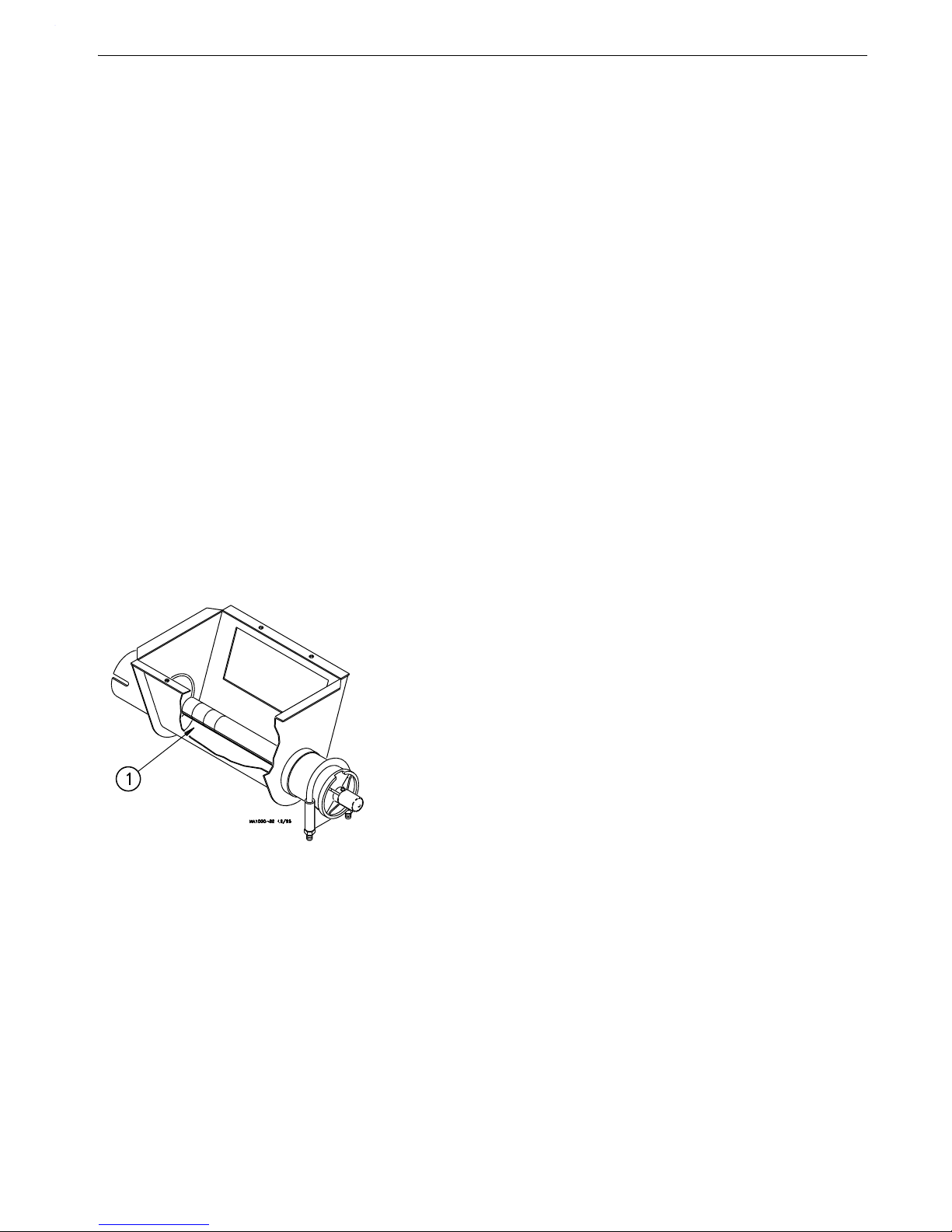
Installation Model 55,75,90, & HMC FLEX-AUGER
Key Description
1 Power Unit
2 Switch Assembly
3 Gearhead End Plate
4 Control Body
5 Control Unit Funnel
6 Tube Anchor End
Figure 19.Control Unit/Power Unit Assembly
Control Unit & Power Unit Installation
1.Attach the tube anchor to the appropriate end (determine the best side of control unit for switch placement)
of the control unit body by inserting the 1/4-20x.75 carriage bolts from the inside of the control unit through
the tube anchor and attach 1/4-20 flange hex nut.
2.Connect the power unit to the gearhead end plate using the 5/16-18 machine screws and the flat washers
packed with the control.
3.Attach the gearhead end plate to the control unit body the same as the tube anchor.
4.Insert the lower section of the switch assembly into the control unit and secure the top with the 2 #10x.5
screws provided.
For Single Phase Direct Drive Control Units
1.Connect the electrical wires on the power unit to the control unit.
2.Drill bottom of control unit switch box with 7/8”(22.2mm) hole to receive the 90o connector and motor
wire. Use caution not to disturb any wires or components of the switch box ass’y when drilling holes.
3.Attach the 90 degree connector& conduit to the control unit housing.
4.Attach the insulated motor wires to the terminal block in the control housing: one wire to terminal "3"
and one wire to terminal "4". Attach the bare grounding wire to one of the green colored screws
provided for attaching the grounding wires.
5.Place the adjustable tube clamp on the tube anchor and connect the control unit/power unit assembly to the
end of the FLEX-AUGER tube.
Note:The switch in the control unit is a safety backup switch in case the hopper level switch or drop
tube switch fails to shut off the system. DO NOT use the safety switch to control the FLEXAUGER System. This will cause feed to bridge in the control.
20
MA1702D

Model 55,75,90, & HMC FLEX-AUGER Installation
Key Description
1 Replace shipping plug with
vent plug provided.
2 Chain
3“S” Hook
Figure 20.Control Unit/Power Unit Suspension
Figure 21.Belt Drive Control Unit
6.Support the Power Unit and Control Unit securely. Points are provided at the gear head and the tube anchor
for suspending the equipment with chain and “S” hooks supplied with the delivery system (See Figure 20).
NOTE: Other ways of supporting the delivery system can be used where it is practical, as long as the
supports do not let the equipment sag or do not make flat spots in the auger tubes.
Note:The motor should be fastened to keep it from twisting. "S" hooks and chain can be attached
to the motor base to prevent the motor from shifting.
7.Install the driver assembly on the power unit shaft. Start the socket head screws but leave the anchor clamp
loose enough to slip in the auger.
8.Replace the plastic shipping plug in the gear head with the vent plug provided.
Belt Drive Control Unit Installation
The Belt Drive Control Unit installation is much the same as the direct drive unit. Mount the Belt Drive Adapter
and Motor to the control unit, then proceed with installation to the auger tube as described in this manual.
“Standard Belt Drive Control Units” on page 40 can be used as an assembly guide for the Belt Drive Control
Unit. Figure 21 shows a Belt Drive Control Unit suspended.
MA1702D
21

Installation Model 55,75,90, & HMC FLEX-AUGER
Key Description
1 Model 55 Driver Block
2 Model 55 Driver Tube
Key Description
1 Model 75, 90, & HMC Driver As-
sembly
2 Anchor Clamp
Figure 22.Auger Installation
Auger Installation
Use extreme caution when working with the auger. The auger is under
tension and may spring causing injury. Always wear protective clothing
and protective glasses when working with the auger.
Use extreme caution when pushing the auger into the auger tubes. Keep
your hands away from the end of the auger tube to avoid injury.
Handle the FLEX-AUGER carefully. Dropping the rolls of auger may
cause the auger to kink. Do not install an auger that has a sharp kink in it.
The kink will cause the auger to wear a hole in the tube at that spot. If the
kink cannot be straightened with pliers, the kink must be cut out and the
auger brazed back together. Refer to the "Auger Brazing" section in this manual for the correct brazing procedure.
1.Beginning at the boot, push the auger into the auger tube through the rear of the boot until the auger reaches
the control unit end of the line.
Use extreme caution when pushing the auger into the auger tubes. Keep your hands away from the
end of the auger tube to avoid injury.
2.Attach the auger to the driver by rotating the driver and threading the auger through the anchor clamp.
Figure 22 shows the Model 55 Driver installation procedure. Control Unit not shown for clarity.
Figure 22 shows the Model 75, 90, & HMC Driver installation procedure. Control Unit not shown for
clarity.
3.Rotate the auger so that it is fully engaged on the Driver. Tighten the screws securely to clamp the auger to
the control unit.
22
MA1702D

Model 55,75,90, & HMC FLEX-AUGER Installation
Key Description
1 Anchor and Bearing Assembly
2 Lower Boot
3 Auger
4 Tighten Set Screw to secure Auger
in Clamp Pin
5 Tube Clamp
Figure 23.Anchor and Bearing Installation
Model 90 & HMC Models
Key Description
1 Model 55 Lower Boot
2 Model 55 Auger
3 Auger Clamp
4 Anchor Bearing
5 Tighten socket screw to
secure auger to the Anchor.
6 Anchor
Model 55
4.Assemble the control unit funnel to the tube anchor and the gearhead end plate with 4 1/4-20x.63 hex head
bolts and1/4-20 hex flange nuts. The straight side of the funnel should be position on the power unit side of
the control.
5.Pull on the loose end of the auger at the boot once or twice until it begins to stretch, then release it slowly.
This will bring the auger to its natural length.
IMPORTANT: On Single Boot Systems, Stretch the auger 2 inches (50 mm) for every 50 feet (15.2
m) of length. Example: For a 150 ft. (45 m) system the auger should be cut 6 inches
(150 mm) shorter than its natural length. Measure the amount of stretch from the
rear edge of the boot and cut the auger at that point.
Note: For ease of cutting, measure and mark the auger at the point where it is to be cut. Then, pull
the auger an additional 6-8" (150-200 mm) and use locking pliers to clamp the auger wh i le you
cut it.
6.Figure 23 shows the proper assembly of the Model 55 boot components. Insert the Auger over the Anchor
and through the Auger Clamp until Auger touches washer. Torque Set Screw into Auger Clamp 10-12 ft.-lbs.
Over tightening the Set Screw may cause damage to the Auger Clamp.
Figure 23 shows the proper assembly of the Model 75, 90, & HMC anchor components. Insert the anchor
into the auger until the auger touches the anchor flange. The auger must be threaded onto the Boot Anchor
Assembly, through the clamp pin. Use a 5/16” open-end wrench to tighten the clamp pin setscrew on the
auger.
Some of the Boot Models have Anchor and Bearing Assemblies with Restrictors that may be
shortened, if necessary, to increase capacity.
7.Attach the anchor assembly to the boot.
8.Place the cannonball in the boot.
MA1702D
23

Installation Model 55,75,90, & HMC FLEX-AUGER
Figure 24.Cover Plate Installation
System
Model Model Model
55 Auger 75/HMC Auger 90 Auger
1.0 to 1.13” 1.5 to 1.75” 1.5 to 1.75”
(25 to 29 mm) (38 to 45 mm) (38 to 45 mm)
X=
Note: Sharp Auger Ends at the
to avoid damage to Auger Tube(s).
braze(s) must be filed or ground
Figure 25.Auger Brazing/Filing
Cover Plate Installation
The cover plate is installed after installation of the auger in the tube (See Figure 24).
To install the cover plate:
1.Loosen wing nuts to end of studs
2.Start lower side of cover plate in boot opening.
3.Slide the cover plate up as far as possible so that plate catches top of boot opening.
4.Hold the cover securely while tightening the wing nuts.
Auger Brazing/Filing
If the auger needs to be spliced or lengthened, locate the brazed joint
closer to the power unit to minimize feed flow restriction in the line.
To align the auger for brazing, lay it in angle iron and clamp securely.
Rotate the auger to allow both the inside and outside edges of the augers
to be brazed.
Butt the ends of the auger against each other. DO NOT SCREW ONE
AUGER INSIDE THE OTHER--This restricts the feed flow.
Figure 25 and the associated chart specify how far to lap the augers.
A bronze, flux-coated rod is recommended. The joint should be well filled and smooth so that it does not wear
against the tube. Allow the joint to air cool.
File the auger edges, as shown in Figure 25, to avoid damage to the auger tubes. Also, file off any brazing that
extended beyond the outside radius of the auger flightings.
24
MA1702D
Model 55,75,90, & HMC FLEX-AUGER Installation
Key Description
1 Cut off approximately 1” (25 mm) of the Restrictor Tube to
increase feed flow. Repeat as required.
Figure 26.Restrictor Adjustment Model 90 & HMC Only
Restrictor Adjustment
Some Boots have Restrictors that may be adjusted for increased delivery capacities.
DO NOT ADJUST THE RESTRICTOR UNTIL THE SYSTEM HAS BEEN IN OPERATION AND THE
SYSTEM IS BROKEN IN.
THE MODEL 55 RESTRICTOR IS NOT ADJUSTABLE.
Note:Feed delivery capacities are based on 40 lbs/ ft.3 (640 kg/m3) feed density. Systems using
lighter weight feeds may not be able to achieve the maximum capacities listed.
Note:Always refer to the motor amperage nameplate when increasing the feed flow capacity.
Exceeding the nameplate amperage may result in nuisance motor overload tripping and/or
damage to the system.
1.Loosen the tube clamp on the back of the Lower Boot to remove the Anchor and Bearing Assembly from the
boot.
2.Use extreme caution when working with the auger under tension. Springing auger can cause personal injury.
Pull enough of the auger out of the auger tube to allow the Restrictor Tube to be cut.
Use locking pliers to hold the auger outside the boot.
3.Use a hacksaw to cut 1" (25 mm) at a time off the end of the Restrictor Tube to increase feed flow (See
Figure 26).
4.CAREFULLY remove the locking pliers while holding on to the Anchor and Bearing Assembly and auger
securely.
5.CAREFULLY allow auger to draw the Anchor and Bearing Assembly back into the Lower Boot. DO NOT
ALLOW THE BEARING TO BE SLAMMED BACK INTO THE BOOT.
MA1702D
25

Installation Model 55,75,90, & HMC FLEX-AUGER
Key Description
1 Straight-Out Boot on Terminal Bin (with Baffles)
2 Straight-Thru Boot on Intermediate Bin (w/Baffles)
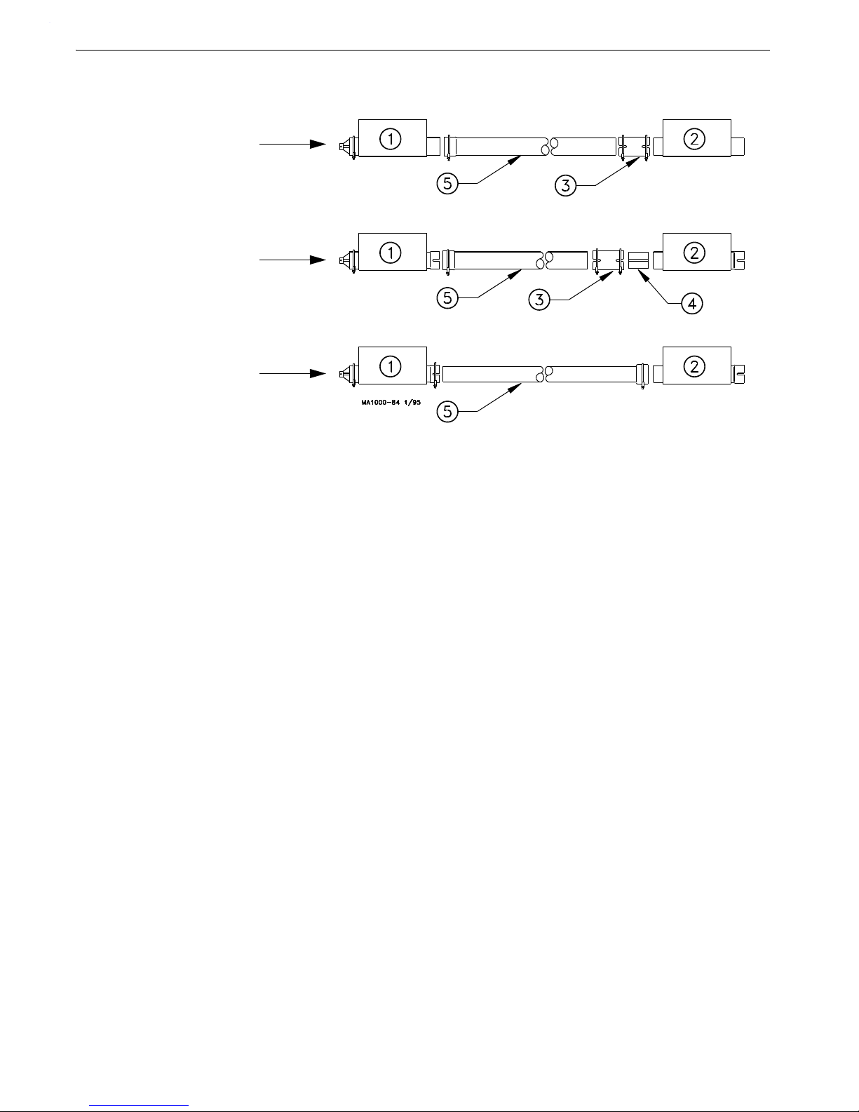
Figure 27.Straight-Through Tandem
Straight-Through Tandem Boot
The Straight-Through Tandem Boots allow one or two augers to remove feed from two separate feed bins. Feed
should only be drawn from one bin at a time.
Solid Cannonballs are used in conjunction with the Boot Baffles.
1.Install boots on both feed bins. Be sure the outlets and inlets on the boots are in line and arrow tape is pointed
in direction of feed flow. Figure 27 shows a typical Straight-Through Tandem System.
2.Measure and cut an auger tube(s) to connect the two boots (See Figure 29).
For Model 90 & HMC FLEX-AUGER systems, the belled end of the auger tube fits directly over the outlet
end the Straight-Out Boot. The straight end of the Auger Tube connects to the incoming end of the StraightThru Boot, using a Tube Connector. (See Figure 29)
For Model 75 FLEX-AUGER (PVC) systems, slide the belled end of the Model 75 Auger Tube over the
outlet of the Straight-Out Boot. The straight end of the Auger Tube connects to the incoming end of the
Straight-Thru Boot, using a Tube Insert and Tube Connector.
For Model 75 FLEX-AUGER (Steel) systems, slide the straight end of the Model 75 Auger Tube into the
outlet end of the Straight-Out Boot. The belled end of the Auger Tube should be slid over the inlet end of the
Straight-Thru Boot. (See Figure 29).
Remember to caulk all tube joints exposed to weather or moisture.
26
MA1702D

Model 55,75,90, & HMC FLEX-AUGER Installation
Figure 28.Straight-Through Tandem
Figure 28.Standard FLEX-AUGER Boots and Baffle Locations
Standard FLEX-AUGER Boots and Baffle Locations
(As Shipped from Factory)
MA1702D
27
Installation Model 55,75,90, & HMC FLEX-AUGER
Model 90
Steel or PVC
&
HMC
PVC
Model 75
PVC
Model 75
Steel
Key Description
1 Straight-Out Boot
2 Straight-Thru Boot
3 Tube Connector
4 Tube Insert
5 Auger Tube
Figure 29.Model 75, 90, & HMC Straight-Through Tandem Boot connections.
3.Push the auger into the line of tubes and anchor it at the power unit end. Stretch the auger 4 inches per 50 feet
(100 mm per 15 m) and cut it even with the rear of the straight-out boot. Notice the auger stretch is not the
same as for Single Boot FLEX-AUGER Systems. Note: For Model 90 3-Bin Systems, stretch auger 6
inches per 50 feet.
4.Use a tube clamp to secure the bearing cap to the boot.
28
MA1702D

Model 55,75,90, & HMC FLEX-AUGER Installation
Model 75 Single Straight-Through System
Model 90 and HMC
Single Straight-Through System
Model 75 Combination Single-Twin
Straight Through System
Model 90 Combination Single-Twin
Straight Through System
Model 75,90, or HMC
Twin Straight-Through System
Model 75,90, or HMC
Twin Straight-Through System
Model 75,90, or HMC
Twin Straight-Through System
Model 90 Three Bin System
Twin Straight-Through System
Model 90 Three Bin System
Twin Straight-Through System
Key Description
1 Single Baffled Boot
2 Twin Baffled Boot (Model 75 or 90) Mount Either Direction
3 Arrow Tape
*
Note:On twin systems running in opposite directions, follow the tape
on the bearing end of the system.
Figure 30.Optional Baffle Configurations
(Requires (1) 6147 3’ Stub Tube
*
*
*
*
*
or (1) 6147SS 3’ Stub Tube
)
Boot Baffles for Straight-Through Boot Systems
The Chore-Time Boot Baffles are for use with dry, coarse, mash, crumbles, or pelleted feeds to prevent boots from
overcharging the system.
The Boot Baffles are intended for use in both “straight-out” & “straight-through” boots. Boot Baffles are factory
installed on Straight-Through Boot Systems.
See Figure 30 for applications and auger direction.
MA1702D
29

Installation Model 55,75,90, & HMC FLEX-AUGER
Important! If system is to be
controlled by another style
switch, please refer to applicable
instruction.
Important! If a time clock is to
be used to control system, please
refer to applicable instruction.
Important:If a time clock is to be
used to control system, please
refer to applicable instruction.
Important! If system is to be
controlled by another style
switch, please refer to applicable
instruction.
Feed Level Control Installation
The Hopper Level Control (or Drop Tube Switch) is installed in the feed hopper (or in the drop tube over the
feeder) at the power unit end of the line. This feed flow control switch stops the FLEX-AUGER System when the
last feeder is full. Install the hopper level control or drop tube switch according to instructions shipped with the
unit.
The wiring diagram for each type of delivery system shows how the hopper level control (drop tube switch is the
same) must be wired into the control unit.
Hopper Level Control Switch (Single Phase) Wiring
Hopper Level Control Switch (Three Phase) Wiring
30
MA1702D

Model 55,75,90, & HMC FLEX-AUGER Installation
Important! If a time clock is to
be used to control system, please
refer to applicable instruction.
SENSOR PLUS™ Electronic Switch (Single Phase) Wiring
MA1702D
31

Operation Model 55,75,90, & HMC FLEX-AUGER
Operation
1.During initial start-up, the boot slide should be only partially open to prevent the auger from being fully
charged. Maintain partially open Slide until feed reaches the far end Control Unit. After that, the boot slide
must be fully open for proper delivery system operation.
2.Do not permit the FLEX-AUGER system to operate empty. Use a time clock or Auger Timer with the system
whenever possible. This reduces short cycling by operating on a preset schedule instead of on demand. It
also prevents excessive running of the system if the bin becomes empty. If the optional boot switch is used,
the fill system will shut down when the bin becomes empty.
3.Program the time clock to fill feeders often so the FLEX-AUGER System does not have to run a long period
of time to get feeders filled. Poultry feeders supplied by the FLEX-AUGER System should be operated by a
time clock so feeders start at the same time. This gives the FLEX-AUGER System a better chance to keep up
with them. Note: The hopper level control must be positioned low in the last feeder hopper.
4.The red light on the control unit will light if feed has packed inside. If this happens, remove feed from the
drop tube and tap the side of the power unit to clear the safety switch. Keep the hopper level control in
adjustment and positioned straight up and down so the paddle swings freely. The safety switch does not take
the place of the hopper level control.
5.If the FLEX-AUGER System must be used to convey high-moisture feed, empty the auger line completely
after each running to prevent the feed from setting up in the tubes.
6.On Baffled Boots, the flow rates are predetermined with factory installed Baffles. The Baffles are nonadjustable.
On Non-Baffled Boots, the restrictor on the boot anchor regulates the amount of feed flowing into
the auger. Start a new system with the restrictor installed as shipped
Allow the system to polish out before adjusting the feed flow. If more feed flow is desirable, the
restrictor may be shortened. Refer to “Restrictor Adjustment” on page 25.
7.When feeding with the Straight-Through Tandem System, open the slide on only one bin at a time!
Start-Up Procedure for New Systems
Important! DO NOT RUN FEED THROUGH A NEW SYSTEM UNTIL AFTER THIS PROCEDURE
HAS BEEN FOLLOWED OR THE AUGER WILL PLUG AND BIND.
1.Close the Slide on the FLEX-AUGER® Boot.
2.Operate the system empty for one minute.
3.Open the slide on the FLEX-AUGER
®
boot no more than 1 inch (25 mm) to allow
some feed into the boot.
4.Operate the system with the slide in this position until feed has reached the Control
Unit. This removes the manufacturing grease and oil from the auger and tubes. If this
grease and oil is not removed, the feed may bunch up causing the auger to plug and
bind.
5.Now the slide can be fully opened and the system operated normally.
32
MA1702D

Model 55,75,90, & HMC FLEX-AUGER Parts Listing
Model 55 Model 75 Model 90 Model HMC
Item Description Part No
1 Boot Assembly See Parts List
2 Control Unit See Parts List
3
Upper Boot
See Parts List
4
45 Degree PVC Elbow 34855 7285 7357 7357
5
Neoprene Seal 6394 2613 5035 5035
6
Seal Ring 2612 2612 2612 2612
7**
Auger 7961-0 4744-0 3942-0 4744-0
8
Plastic Drop Tube 1932 1932 6381 6381
9
Telescoping Drop Tube 14366-1932 14366-1932 14366-6381 14366-6381
10 Power Unit See Parts List
11 Outlet Drop Kit w/Clamps 43455C 43475C 43490C 43490C
Outlet Drop Kit w/Retainers 43455R 43475R 43490R 43490R
12 Extension Hopper 40170 7944 7869 7849
13 Suspension Kit 5043
S Hooks (Qty 25) 2805 2805 2805 2805
Screw Hooks (Qty 12) 1214 1214 1214 1214
***Chain (25’) [7.62 m] 2128 2128 2128 2128
14 Suspension Kit (Stainless Steel) 5043SS*
Stainless S Hooks (Qty 25) 2805SS* 2805SS* 2805SS* 2805SS*
Stainless Screw Hooks (Qty 12) 1214SS* 1214SS* 1214SS* 1214SS*
***Stainless Chain (25’) [7.62 m] 2128-25SS* 2128-25SS* 2128-25SS* 2128-25SS*
15 PVC Auger Tube 7955 6516 6293 6293
16 Tube Clamp Kit 7976 6515 6721 6721
* SS = Stainless Steel.
**Model 55 Auger (Part No. 7961-0) may be ordered in lengths from 20 ft. to 400 ft. maximum. Example: 7961-155 would be 155’ of auger.
Model 75 Auger (Part No. 4744-0) may be ordered in lengths from 20 ft. to 300 ft. maximum. Example: 4744-155 would be 155’ of auger.
Model 90 Auger (Part No. 6942-0) may be ordered in lengths from 20 ft. to 250 ft. maximum. Example: 6942-155 would be 155’ of auger.
***Chain can be purchased in a 25’ [7.62 m] bag (2128-25 or 2128-25SS*), a box of 100’ [30.48 m] (2128-100 or 2128-100SS*)
or a 250’ [76.2 m] reel (2128-250 or 2128-250SS*).
1
2
3
4
5
6
7
8
9
10
11
12
13
15
16
14
Model 55 Model 75 Model 90 Model HMC
Item Description Part No
1 10’ [3 m] Steel Tube ---- 2088 5091 ---2 45 Degree Hardened Steel Elbow ---- 14324 6472 ---3 Tube Connector Kit ---- 2103 6595 ----
Parts Listing
Model 55,75,90,& HMC Feed Delivery System Standard Components
Steel Components
MA1702D
33

Parts Listing Model 55,75,90, & HMC FLEX-AUGER
Part Number HP RPM Phase Hz Voltage Usages
3259-49 1.0 HP 348 RPM Single 60 Hz 230 Model 75, 90, & HMC
3259-50 1/2 HP 216 RPM Single 60 Hz 230 Model 75/90 Two Motor Tandem
3259-51 1/2 HP 348 RPM Single 60 Hz 230 Model 75, 90, & HMC
3259-52 3/4 HP 348 RPM Single 60 Hz 230 Model 75, 90, & HMC
3259-67 1/2 HP 129 RPM Single 60 Hz 230 Model 75, & HMC
3259-77 1/2 HP 425 RPM Single 60 Hz 230 Model 90
3259-78 3/4 HP 425 RPM Single 60 Hz 230 Model 90
3259-79 1.0 HP 425 RPM Single 60 Hz 230 Model 90
3259-89 1.0 HP 348 RPM Single 50 Hz 220 Model 75, 90, & HMC
3259-34 1/3 HP 348 RPM Single 60 Hz 230 Model 55 only
3259-39 1/2 HP 348 RPM Single 60 Hz 230 Model 55 only
3259-98 1/2 HP 348 RPM Single 50 Hz 220 Model 55 only
3259-88 3/4 HP 348 RPM Single 50 Hz 220 Model 75 & 90
3259-108 1.0 HP 474 RPM Single 50 Hz 220 Model 90
3259-109 1/2 HP 180 RPM Single 50 Hz 220 Model 75, & HMC
3259-148 1.0 HP 580 RPM Single 50 Hz 220 Model 90
3259-136 3/4 HP 216 RPM Single 60 Hz 230 Model 75, & HMC
3259-122 3/4 HP 584 RPM Single 60 Hz 230 Model 90
3259-123 1.0 HP 584 RPM Single 60 Hz 230 Model 90
3259-124 1.5 HP 584 RPM Single 60 Hz 230 Model 90
3259-137 1.0 HP 584 RPM Three 60 Hz 200 Model 90
3259-102 1/2 HP 180 RPM Three 50 Hz 220/380-415 Model 75 & HMC
3259-105 1.0 HP 348 RPM Three 50 Hz 220/380-415 Model 75 & 90
3259-107 1.0 HP 474 RPM Three 50 Hz 220/380-415 Model 90
3259-117 1.0 HP 348 RPM Three 60 Hz 208-230/460 Model 75, 90, & HMC
3259-118 1.0 HP 425 RPM Three 60 Hz 208-230-460 Model 75 & 90
3259-120 3/4 HP 425 RPM Three 60 Hz 208-230-460 Model 75 & 90
3259-119 3/4 HP 348 RPM Three 60 Hz 208-230/460 Model 75, 90, & HMC
3259-134 1/2 HP 348 RPM Three 60 Hz 220-240/380-400 Model 55
3259-137 1.5 HP 584 RPM Three 60 Hz 200/380 Model 90
3259-150 1.0 HP 580 RPM Three 50 Hz 220/380 Model 90
3259-151 1.5 HP 580 RPM Three 50 Hz 220/380 Model 90
3259-152 1.0 HP 584 RPM Three 60 Hz 220/380 Model 90
Power Unit Assembly Part Numbers
34
MA1702D

Model 55,75,90, & HMC FLEX-AUGER Parts Listing
3259-49 3259-50 3259-51 3259-52 3259-89 3259-102 3259-67
Key
Description Part No. Part No. Part No. Part No. Part No. Part No. Part No.
1 Motor 6857 5050 5050 5051 26157 28033 5703
4 Pipe Plug 2755 2755 2755 2755 2755 2755 2755
5 Gearhead 3261-7 3261-6 3261-7 3261-7 3261-10 3261-6 3261-8
6 Vent Plug 3523 3523 3523 3523 3523 3523 3523
7 S Hook 4270 4270 4270 4270 4270 4270 4270
8 Pinion Assembly 6104 3249 5046 5046 6104 3249 3245
9 Magnetic Pipe Plug 30160 30160 30160 30160 30160 30160 30160
3259-34 3259-39 3259-98 3259-88 3259-107 3259-108 3259-109
Key
Description Part No. Part No. Part No. Part No. Part No. Part No. Part No.
1 Motor 4229 5703 5977 6305 28035 26157 5977
2 90 Degree Connector 4228 4228 - - - - - - - - - - - - - - - - - - - 3 Anti-Short Bushing 6304 6304 - - - - - - - - - - - - - - - - - - - 4 Pipe Plug 2755 2755 2755 2755 2755 2755 2755
5 Gearhead 3261-5 3261-5 3261-11 3261-10 3261-13 3261-13 3261-6
6 Vent Plug 3523 3523 3523 3523 3523 3523 3523
7 S Hook 4270 4270 4270 4270 4270 4270 4270
8 Pinion Assembly 5046 5046 5046 5046 6104 6104 3249
9 Magnetic Pipe Plug 30160 30160 30160 30160 30160 30160 30160
3259-117 3259-119 3259-105 3259-77 3259-78 3259-79 3259-136
Key
Description Part No. Part No. Part No. Part No. Part No. Part No. Part No.
1 Motor 34101 34102 28035 5050 5051 6857 5051
4 Pipe Plug 2755 2755 2755 2755 2755 2755 2755
5 Gearhead 3261-7 3261-7 3261-10 3261-10 3261-10 3261-10 3261-6
6 Vent Plug 3523 3523 3523 3523 3523 3523 3523
7 S Hook 4270 4270 4270 4270 4270 4270 4270
8 Pinion Assembly 6104 5046 6104 5052 5052 6106 3245
9 Magnetic Pipe Plug 30160 30160 30160 30160 30160 30160 30160
3259-122 3259-123 3259-124 3259-137 3259-118 3259-120
Key
Description Part No. Part No. Part No. Part No. Part No. Part No.
1 Motor 5051 6857 8782 28036EUR 34101 34102
4 Pipe Plug 2755 2755 2755 2755 2755 2755
5 Gearhead 3261-13 3261-13 3261-13 3261-13 3261-10 3261-10
6 Vent Plug 3523 3523 3523 3523 3523 3523
7 S Hook 4270 4270 4270 4270 4270 4270
8 Pinion Assembly 5052 6106 6106 6106 6106 5052
9 Magnetic Pipe Plug 30160 30160 30160 30160 30160 30160
3259-134 3259-137 3259-148 3259-150 3259-151 3259-152
Key
Description Part No. Part No. Part No. Part No. Part No. Part No.
1 Motor 28031EUR 28036EUR 26157 28035EUR 28036EUR 28035EUR
4 Pipe Plug 2755 2755 2755 2755 2755 2755
5 Gearhead 3261-5 3261-13 3261-16 3261-16 3261-16 3261-13
6 Vent Plug 3523 3523 3523 3523 3523 3523
7 S Hook 4270 4270 4270 4270 4270 4270
8 Pinion Assembly 5046 6104 6104 6104 6104 6104
9 Magnetic Pipe Plug 30160 30160 30160 30160 30160 30160
9
4
5
1
2
3
6
7
8
3259-0 Power Units
MA1702D
35

Parts Listing Model 55,75,90, & HMC FLEX-AUGER
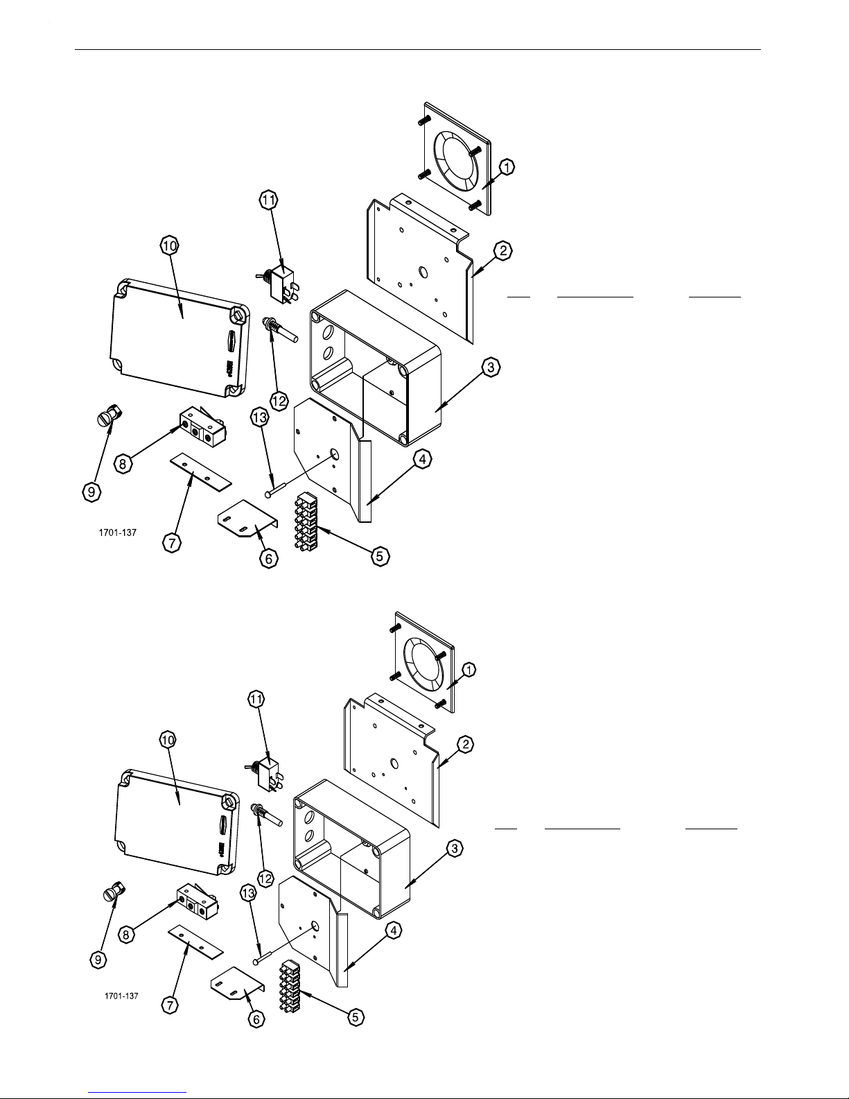
Model 55 Model 75 Model 90 Model HMC
46800-1 46800-2 46800-4 46800-3
KEY
DESCRIPTION PART NO. PART NO. PART NO. PART NO.
1 Gearhead End Plate 43596 43596 43596 43596
2 Control Unit Body 43601 43601 43601 43601
3 Tube Anchor Plate Weldment 45924 45925 45926 45926
4 Control Unit Funnel 45943-1 45943-1 45943-2 45943-2
5 Switch & Plate Assembly 46051 46051 46051 46051
6 H.D. Adjustable Clamp 47652-1 47652-1 47652-1 47652-1
7 Water Tight Connector 23810 23810 23810 23810
8 Non-Metal Flex Conduit 26982-10 26982-10 26982-10 26982-10
9* Driver Weldment 7704 7706 7704
10* Anchor Clamp 7703 7703 7703
11* 5/16-18x1/2” Socket Hd Cap Screw 6850-3 6850-3 6850-3
12* 5/16-18x2-1/2” Socket Hd Cap Screw 6850-4 6850-4 6850-4
13* Drive Tube 2920
14* Drive Block 4642
15* Flat Washer 1484
16* 1/4-20x1-1/2” Screw 5083-8
-- Driver Assembly 46458 6862 6861 6862
*Parts included in Driver Assembly (Part No’s 46458,6862, or 5861 respectively.
Direct Drive Control Unit (Single Phase)
36
MA1702D

Model 55,75,90, & HMC FLEX-AUGER Parts Listing
Model 55 Model 75 Model 90 Model HMC
46800-27 46800-28 46800-30 46800-29
KEY
DESCRIPTION PART NO. PART NO. PART NO. PART NO.
1 Gearhead End Plate 43596SS 43596SS 43596SS 43596SS
2 Control Unit Body 43601 43601 43601 43601
3 Tube Anchor Plate Weldment 45924 45925 45926 45926
4 Control Unit Funnel 45943-1 45943-1 45943-2 45943-2
5 Switch & Plate Assembly 46051SS 46051SS 46051SS 46051SS
6 H.D. Adjustable Clamp 47652-1 47652-1 47652-1 47652-1
7 Water Tight Connector 23810 23810 23810 23810
8 Non-Metal Flex Conduit 26982-10 26982-10 26982-10 26982-10
9* Driver Weldment 7704 7706 7704
10* Anchor Clamp 7703 7703 7703
11* 5/16-18x1/2” Socket Hd Cap Screw 6850-3 6850-3 6850-3
12* 5/16-18x2-1/2” Socket Hd Cap Screw 6850-4 6850-4 6850-4
13* Drive Tube 2920
14* Drive Block 4642
15* Flat Washer 1484
16* 1/4-20x1-1/2” Screw 5083-8
-- Driver Assembly 46458 6862 6861 6862
17 1/4-20 Rd. Hd. Sq Shnk. Bolt (SS) 7550-6 7550-6 7550-6 7550-6
18 1/4-20 Hx Flg. Serr. Nut (SS) 46298 46298 46298 46298
19 #10-14 Twin Helix Screw (SS) 28075SS 28075SS 28075SS 28075SS
*Parts included in Driver Assembly (Part No’s 46458,6862, or 5861 respectively.
Model 55 Model 75 Model 90 Model HMC
46800-31 46800-32 46800-34 46800-33
Components - Same as Standard Direct Drive Control Units except does not include the 90
o
connectors and the flex conduit
Stainless Steel Direct Drive Control Unit (Single Phase)
International Direct Drive Control Units (3 Phase)
MA1702D
37
Parts Listing Model 55,75,90, & HMC FLEX-AUGER
KEY DESCRIPTION PART NO.
1 Diaphragm Assembly 46159
2 Switch Cover Plate 46030
3 4x6 Electrical Box 46070-1
4 Mount Panel 46072
5 Terminal Block 34925-6
6 Switch Bracket 46093
7 Switch Insulation 1907-5
8 Micro Switch 46091
9 Plastic Screw 42849
10 4x6 Elect Box Cover 42851
11 Toggle Switch 7767
12 Pilot Light 46047
13 Rivet, 3/16 x 1.00
round Head(S.S.) 46906
KEY DESCRIPTION PART NO.
1 Diaphragm Assembly 46159
2 Switch Cover Plate (SS 46030SS
3 4x6 Electrical Box 46070-1
4 Mount Panel 46072
5 Terminal Block 34925-6
6 Switch Bracket 46093
7 Switch Insulation 1907-5
8 Micro Switch 46091
9 Plastic Screw 42849
10 4x6 Elect Box Cover 42851
11 Toggle Switch 7767
12 Pilot Light 46047
13 Rivet, 3/16 x 1.00
round Head(S.S.) 46906
46051 Switch & Plate Assembly
46051SS Switch & Plate Assembly
38
MA1702D

Model 55,75,90, & HMC FLEX-AUGER Parts Listing
This page left blank intentionally.....
MA1702D
39

Parts Listing Model 55,75,90, & HMC FLEX-AUGER
40
MA1702D
Standard Belt Drive Control Units
Model 55 Model 75 Model 90 Model HMC
46800-11 46800-12 46800-14 46800-13
KEY
DESCRIPTION PART NO. PART NO. PART NO. PART NO.
-- Control Unit 46800-6 46800-7 46800-9 46800-8
--* Belt Drive Parts Package 46138-1 46138-2 46138-2 46138-2
*See separate parts list “Boot Components” on page 43 for individual components.
Note: The Belt Drive Control Units include all the Direct Drive Control Unit components, plus the following components.

Model 55,75,90, & HMC FLEX-AUGER Parts Listing
MA1702D
41
Part Number
Item Description Model 55 Model 75, 90, and HMC
1
1
Model 55 Driver Shaft 27126 --
2
2
Model 75, 90, & HMC Driver Shaft -- 46156
*3
1,2
Grease Fitting 6021 6021
*4
1,2
Flange Bearing 2196 2196
*5
1,2
Front Plate Bearing Holder 2047 2047
*6
1,2
Ball Bearing 5930 5930
7 Adjustment Bracket 46301 46301
8 11" Dia. Sheave 46190 46190
9
1,2
5/8" Set Collar 1386 1386
10 2.25" Dia. Sheave 3208 3208
11 Motor Mount Weldment 3058 3058
12 "V" Gripnotch Belt 4409 4409
13 5/16-18 Hex Locknut 2148 2148
14 5/16-18 Hex Locknut 593 593
15 5/16 Flat Washer 546 546
16 5/16-18x1-3/4" Hex Hd. M.S. 4412-4 4412-4
17 5/16-18 Hex Lock Nut 2148 2148
18
1,2
3/16" Key 2112-1 2112-1
20 5/16-18 Hex Nut 2145 2145
21 Eyebolt 1503-2 1503-2
22 Belt Guard Mount 46198 46198
23 Belt Guard 46199 46199
24 Angle Guard Mount 46299 46299
* May be ordered as Bearing Assembly (Part no. 2096)
1
May be ordered as Bearing and Shaft Assembly (Part no. 46486)
2
May be ordered as Bearing and Shaft Assembly (Part no. 46157)
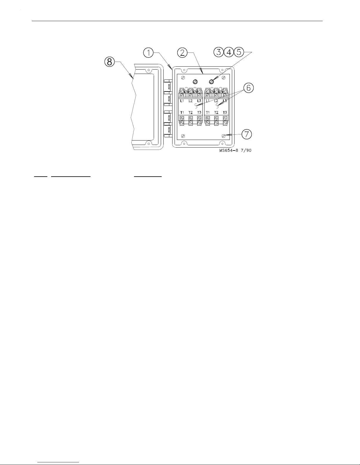
Parts Listing Model 55,75,90, & HMC FLEX-AUGER
Key Description Part No.
1 Box 30860-3
2 Mounting Plate Support 41436
3 #10 Ext. Lock washer 305
4 #10-32 Hex Screw 34662
5 Cup Washer 5775
6 Contactor 55503-230
7 #10-24 Pan Head Screw 46011
8 Lid 30859-2
The Contactor Box containing (1) 55503-230 Contactor may be ordered under Part No.
24392-1.
The Contactor Box containing (2) 55503-230 Contactors may be ordered under Part No.
24392-2.
The Contactor Box containing (3) 55503-230 Contactors may be ordered under Part No.
24392-3.
24392-0 Contactor Box
42
MA1702D

Model 55,75,90, & HMC FLEX-AUGER Parts Listing
Boot Components
Note: The Parts Listings on the following pages provide the parts numbers associated with this
drawing. Be sure to refer to the appropriate page for your model of FLEX-AUGER.
MA1702D
43

Parts Listing Model 55,75,90, & HMC FLEX-AUGER
30 Degree 30 Degree 30 Degree
Item Description Single Boot Twin Boot Quad Boot
--
5
Complete System 8465
5
8466
5
8467
5
--
2
Lower Boot Assembly 9313 9314 9315
1A
6
30 Degree Upper Boot 4347R
6
4347R
6
4347R
6
2
3
Transfer Plate 4359 4359 4359
3
3
Slide 4357 4357 36091
4
3
Slide Shield 4876 4876 4876
5
3
Chain Assembly 27374 27374 27374
7 Neoprene Seal 6394 6394 6394
8 Seal Ring 2612 2612 2612
9 Tube Clamp 29515 29515 29515
10 Cannonball 3621 3621 3621
11 Single Boot Body 7999 - - - - - - - 13
1
Model 55 Anchor 39410 39410 39410
141Auger Clamp 39205 39205 39205
15
1
Socket Head Screw 6850-7 6850-7 6850-7
161Anchor Bearing 39407 39407 39407
171Set Collar 1386 1386 1386
20 Cap 29523 29523 29523
21 Stub Tube 4163 4163 4163
22
4
Back Plate Weldment 6298 6298 6298
23
4
Clean-Out Cover 6301 6301 6301
24 Quad Boot Weldment - - - - - - - - 7980
25 Outlet Cover - - - - - - - - 8026
26B Tube Clamp 29520 29520 29520
39
4
Sealing Washer 8491 8491 8491
4045/16-18 Wing Nut 2146 2146 2146
42 5” Stub Tube 8555 8555 8555
56 Twin Boot Body Weldment - - - - 7998 - - - 58
3
Hairpin 13906 13906 13906
1
These components may be ordered as a Model 55 Anchor Bearing Assembly under Chore-Time Part No. 39405.
2
Items 2 through 56 and item 58 (as listed above) make up the Lower Boot Assemblies (Single, Twin, or Quad).
3
Items 2 through 5 and item 58 may be ordered under Chore-Time Part No. 6284 or 6284SS*.
4
Items 22, 23, 39, & 40 may be ordered under Chore-Time Part No. 6197 or 6197SS* Clean-Out Cover Ass’y.
5
All Complete Systems will come with transparent Red upper boot(s) unless specified with a “C” (i.e. Complete System
# 8465C) This “C” indicates the Complete System will come with a transparent Clear upper boot.
6
Upper boot Part No.’s will have a suffix “R” for transparent Red upper boots (i.e. 4347R) or will have a suffix “C” for
transparent Clear upper boots (i.e. 4347C).
Model 55 Boot Components
See “Boot Components” on page 43 for Part Schematic.
44
MA1702D
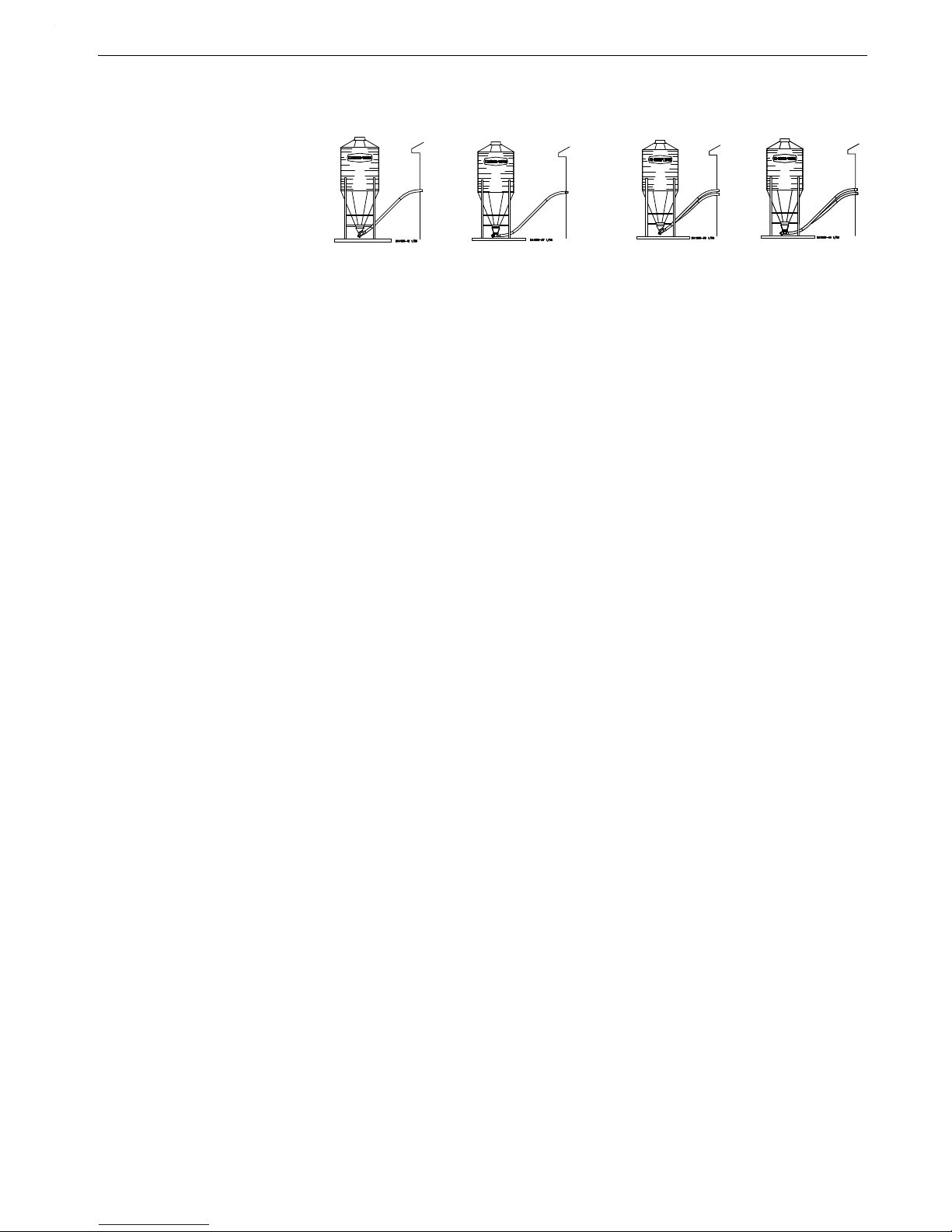
Model 55,75,90, & HMC FLEX-AUGER Parts Listing
30 Degree Straight-Out 30 Degree Straight-Out
Item Description Single Boot Single Boot Twin Boot Twin Boot
--
5
Complete System 65395 or 6539SS5*
65405 or 6540SS5* 68735 or 6873SS5* 36 80 15 or 36801SS5*
--
2
Lower Boot Assembly 36442 or 36442SS* 36589/ or 36589SS* 36389 or 36389SS* 36390 or 36390SS*
1A630 Degree Upper Boot 4347R
6
- - - - 4347R
6
- - - -
1B6Straight Out Upper Boot - - - - 6093R
6
- - - - 6093R
6
2
3
Transfer Plate Weldment 4359 4359 4359 36641
3
3
Slide 4357 or 4357SS* 4357 or 4357SS* 4357 or 4357SS* ----
4
3
Slide Shield 4876 4876 4876 14827
5
3,8
Chain Assembly 27374 27374 27374 27374
7 Neoprene Seal 2613 2613 2613 2613
8 Seal Ring 2612 2612 2612 2612
10 Cannonball 3531 3531 3531 3531
11 Single Boot Body 36588 or 36588SS* 36588 or 36588SS* - - - - - - - 12 Twin Boot Body - - - - - - - - 36350 or 36350SS* 36350 or 36350SS*
22
4
Back Plate Weldment 6298 or 6298SS* 6298 or 6298SS* 6298 or 6298SS* 6298 or 6298SS*
234Clean-Out Cover 6301 or 6301SS* 6301or 6301SS* 6301 or 6301SS* 6301 or 6301SS*
26A Tube Clamp Kit 6515 6515 6515 6515
28
1
5/16-18 x 3/8” Set Screw 1174 1174 1174 1174
2915/8” Set Collar 1386 1386 1386 1386
341Clamp Pin 4702 4702 4702 4702
35
1
5/16-18 x 1/2” Set Screw 5095 5095 5095 5095
361Anchor Shaft 43281 43281 43281 43281
394Sealing Washer 8491 or 8491SS* 8491 or 8491SS* 8491or 8491SS* 8491 or 8491SS*
40
4
5/16-18 Wing Nut 2146 or 2146SS* 2146 or 2146SS* 2146 or 2146SS* 2146 or 2146SS*
411Tube Clamp Kit 4141 4141 4141 4141
4272.75 x 3.0 Tube 6147 6147 6147 6147
44 Bearing Cap 35440 35440 35440 35440
45
1
Safety Cap 29702 29702 29702 29702
46
1
Anchor Tube Weldment 6840 6840 6840 6840
47 S-O/S-T Single Baffle - - - - 35731 or 35731SS* - - - - - - - 48 30° Single Baffle 35732 or 35732SS* - - - - - - - - - - - 49 Cannon Ball Guard - - - - - - - - 35843 or 35843SS* - - - 50 Twin End Baffle (75) - - - - - - - - 35845 or 35845SS* - - - 54 Twin End Baffle (75) - - - - - - - - - - - - 35845 or 35845SS*
55 Twin Outlet Baffle (75) - - - - - - - - - - - - 35846 or 35846SS*
58
3,8
Hairpin 13906 13906 13906 13906
598Slide - - - - - - - - - - - - 14821 or 14821SS*
60
8
Transfer Plate Assembly - - - - - - - - - - - - 36642
61
8
Slide Shield Assembly - - - - - - - - - - - - 14827
1
These components may be ordered as a Model 75 Anchor Bearing Assembly under Chore-Time Part No. 37346 with Long
Restrictor and Chore-Time Part No. 37347 with Short Restrictor.
2
Items 2 through 55 and item 58 (as listed above) make up the Lower Boot Assemblies (Single or Twin).
3
Items 2 through 5 and item 58 may be ordered under Chore-Time Part No. 6284 or 6284SS*.
4
Items 22, 23, 39, & 40 may be ordered under Chore-Time Part No. 6197 or 6197SS* Clean-Out Cover Ass’y.
5
All Complete Systems will come with transparent Red upper boot(s) unless specified with a “C” (i.e. Complete System #
6539C) This “C” indicates the Complete System will come with transparent Clear upper boot(s).
6
Upper boot Part No.’s will have a suffix “R” for transparent Red upper boots (i.e. 4347R) or will have a suffix “C” for
transparent Clear upper boots (i.e. 4347C).
7
Stub Tube (Item 42) For Opposing Anchor.
8
Included in 36683 Twin Boot Slide Assembly.
*SS=Stainless Steel.
Model 75 Boot Components
See “Boot Components” on page 43 for Part Schematic.
MA1702D
45
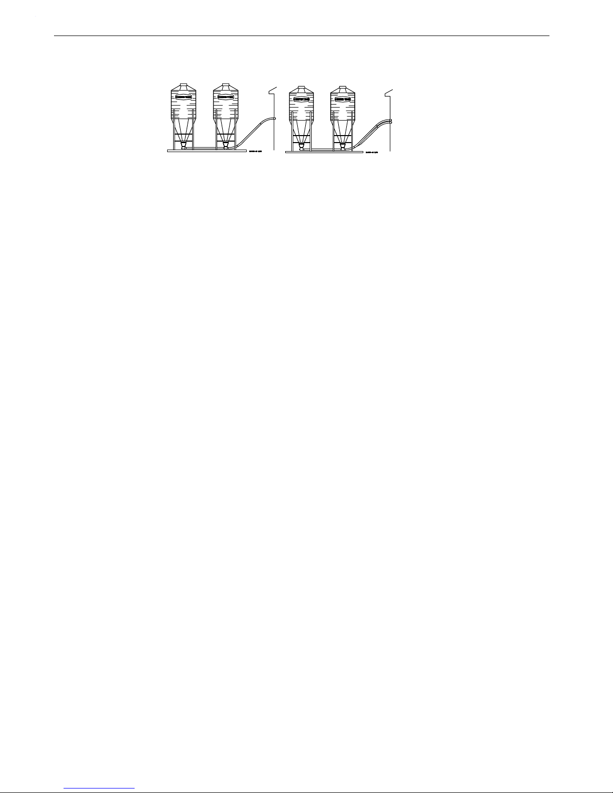
Parts Listing Model 55,75,90, & HMC FLEX-AUGER
Straight-Thru Straight-Thru
Item Description Single Tandem Twin Tandem
--
5
Complete System 65415or 6541SS5* 358805 or 35880SS5*
--
2
Lower Boot Package 36590 or 36590SS* 36394 or 36394SS*
1A630 Degree Upper Boot - - - - - - - 1B6Straight Out Upper Boot 6093R
6
6093R
6
2
3
Transfer Plate Weldment 4359 - - - 3
3
Slide 4357 or 4357SS* - - - 4
3
Slide Shield 4876 - - - 5
3,8
Chain Assembly 27374 27374
7 Neoprene Seal 2613 2613
8 Seal Ring 2612 2612
10 Cannonball 3531 3531
11 Single Boot Body 36588 or 36558SS* - - - 12 Twin Boot Body Weldment - - - - 36350 or 36350SS*
22
4
Back Plate Weldment 6298 or 6298SS* 6298 or 6298SS*
234Clean-Out Cover 6301 or 6301SS* 6301 or 6301SS*
26A Tube Clamp Kit 6515 6515
28
1
5/16-18 x 3/8” Set Screw 1174 1174
2915/8” Set Collar 1386 1386
341Clamp Pin 4702 4702
35
1
5/16-18 x 1/2” Set Screw 5095 5095
361Anchor Shaft 37345 37345
394Sealing Washer 8491 or 8491SS* 8491 or 8491SS*
40
4
5/16-18 Wing Nut 2146 or 2146SS* 2146 or 2146SS*
41 Tube Clamp Kit 4141 4141
4272.75 x 3.0 Tube 6147 6147
43 Insert 6524 6524
44
1
Bearing Cap 35440 35440
451Safety Cap 29702 29702
46
1
Anchor Tube Weldment 6840 6840
47 S-O/S-T Single Baffle 35731 or 35731SS* - - - 54 Twin End Baffle (75) - - - - 35845 or 35845SS*
55 Twin Outlet Baffle (75) - - - - 35846 or 35846SS*
57 Tube Connector 6512 6512
58
3,8
Hairpin 13906 13906
59
8
Slide - - - - 14821 or 14821SS*
608Transfer Plate Assembly - - - - 36642
61
8
Slide Shield Assembly - - - - 14827
1
These components may be ordered as a Model 75 Anchor Bearing Assembly under Chore-Time Part No. 37346 with Long
Restrictor and Chore-Time Part No. 37347 with Short Restrictor.
2
Items 2 through 55 and item 58 (as listed above) make up the Lower Boot Packages (Single or Twin).
3
Items 2 through 5 and item 58 may be ordered under Chore-Time Part No. 6284 or 6284SS.
4
Items 22, 23, 39, & 40 may be ordered under Chore-Time Part No. 6197 or 6197SS Clean-Out Cover Ass’y.
5
All Complete Systems will come with transparent Red upper boot(s) unless specified with a “C” (i.e. Complete System
# 6541C) This “C” indicates the Complete System will come with transparent Clear upper boot(s).
6
Upper boot Part No.’s will have a suffix “R” for transparent Red upper boots (i.e. 4347R) or will have a suffix “C” for
transparent Clear upper boots (i.e. 4347C).
7
Stub Tube (Item 42) For Opposing Anchor.
8
Included in 36683 Twin Boot Slide Assembly.
*SS=Stainless Steel.
Model 75 Boot Components (continued)
See “Boot Components” on page 43 for Part Schematic.
46
MA1702D
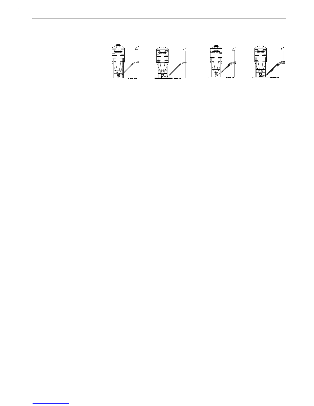
Model 55,75,90, & HMC FLEX-AUGER Parts Listing
30 Degree Straight-Out 30 Degree Straight-Out
Item Description Single Boot Single Boot Twin Boot Twin Boot
--
5
Complete System 61615 or 6161SS5* 61875 or 6187SS5* 68745 or 6874SS5* 65355or 6535SS5*
--
2
Lower Boot Assembly 9301 or 9301SS* 36435 or 36435SS* 36391 or 36391SS* 3 6398 or 363 98SS*
1A630 Degree Upper Boot 4347R
6
- - - - 4347R
6
- - - -
1B6Straight Out Upper Boot - - - - 6093R
6
- - - - 6093R
6
2
3
Transfer Plate Weldment 4359 4359 4359 - - - -
3
3
Slide 4357 or 4357SS* 4357 or 4357SS* 4357 or 4357SS* - - - -
4
3
Slide Shield 4876 4876 4876 - - - -
5
3,7
Chain Assembly 27374 27374 27374 27374
7 Neoprene Seal 5035 5035 5035 5035
8 Seal Ring 2612 2612 2612 2612
10 Cannonball 3531 3531 3531 3531
11 Single Boot Body 28873 or 28873SS* 36433 or 36433SS* - - - - - - - 12 Twin Boot Body - - - - - - - - 36354 or 36354SS* 36354 or 36354SS*
22
4
Back Plate Weldment 6298 or 6298SS* 6298 or 6298SS* 6298 or 6298SS* 6298 or 6298SS*
234Clean-Out Cover 6301 or 6301SS* 6301 or 6301SS* 6301 or 6301SS* 6301 or 6301SS*
26A Tube Clamp Kit 6721 6721 6721 6721
28
1
5/16-18 x 3/8” Set Screw 1174 1174 1174 1174
2915/8” Set Collar 1386 1386 1386 1386
341Clamp Pin 4702 4702 4702 4702
35
1
5/16-18 x 1/2” Set Screw 5095 5095 5095 5095
361Anchor Shaft 43281 43281 43281 43281
371Anchor Tube Weldment - - - - 26048 26048 26048
38
1
Clamp Spacer 5009 5009 5009 5009
394Sealing Washer 8491 or 8491SS* 8491 or 8491SS* 8491 or 8491SS* 8491 or 8491SS*
4045/16-18 Wing Nut 2146 or 2146SS* 2146 2146SS* 2146 2146SS* 2146 2146SS*
41 Tube Clamp Kit 6721 6721 6721 6721
44
1
Bearing Cap Assembly 34830 34830 34830 34830
451Safety Cap 29702 29702 29702 29702
46
1
Anchor Tube Weldment 6833 - - - - - - - - - - - -
49 Cannonball Guard - - - - - - - - 35843 or 35843SS* - - - 50 Twin End Baffle (90) - - - - - - - - 36026 or 36026SS* - - - 51 Single Inlet Baffle (90) - - - - 35998 or 35998SS* - - - - - - - 52 Single Outlet Baffle (90) - - - - 35999 or 35999SS* - - - - - - - 54 Twin Inlet Baffle (90) - - - - - - - - - - - - 36000 or 36000SS*
55 Twin Outlet Baffle (90) - - - - - - - - - - - - 36001 or 36001SS*
58
3,7
Hairpin 13906 13906 13906 13906
59
7
Slide - - - - - - - - - - - - 1 4 8 2 1 o r 1 4 8 2 1 S S *
60
7
Transfer Plate Assembly - - - - - - - - - - - - 36642
617Slide Shield Assembly - - - - - - - - - - - - 14827
1
These components may be ordered as a Model 90 Anchor Bearing Assembly under Chore-Time Part No. 35345 with Short
Restrictor (except for 30° Single Boot Systems, order Part No. 35343 with Long Restrictor).
2
Items 2 through 55 and item 58 (as listed above) make up the Lower Boot Assemblies (Single or Twin).
3
Items 2 through 5 and item 58 may be ordered under Chore-Time Part No. 6284 or 6284SS.
4
Items 22, 23, 39, & 40 may be ordered under Chore-Time Part No. 6197 or 6197SS Clean-Out Cover Ass’y.
5
All Complete Systems will come with transparent Red upper boot(s) unless specified with a “C” (i.e. Complete System #
6161C) This “C” indicates the Complete System will come with a transparent Clear upper boot(s).
6
Upper boot Part No.’s will have a suffix “R” for transparent Red upper boots (i.e. 4347R) or will have a suffix “C” for
transparent Clear upper boots (i.e. 4347C).
7
Included in 36683 Twin Boot Slide Assembly.
*SS=Stainless Steel.
Model 90 Boot Components
See “Boot Components” on page 43 for Part Schematic.
MA1702D
47

Parts Listing Model 55,75,90, & HMC FLEX-AUGER
Straight-Thru Straight-Thru Twin Straight-Thru
Item Description Single Tandem Twin Tandem Three Bin System
--
5
Complete System 62815 or 6281SS5* 65385or 6538SS5* 486605 or 48660SS5*
--
2
Lower Boot Package 36434 or 36434SS* 36388 or 36388SS* 48661 or 48661SS*
1B6Straight Out Upper Boot 6093R
6
6093R
6
6093R
6
2
3
Transfer Plate Weldment 4359 - - - - - - - -
3
3
Slide 4357 or 4357SS* - - - - - - - -
4
3
Slide Shield 4876 - - - - - - - -
5
3
Chain Assembly 27374 27374 27374
7 Neoprene Seal 5035 5035 5035
8 Seal Ring 2612 2612 2612
10 Cannonball 3531 3531 3531
11 Single Boot Body 36433 or 36433SS* - - - - - - - 12 Twin Boot Body Weldment - - - - 36354 or 36354SS* 36354 or 36354SS*
22
4
Back Plate Weldment 6298 or 6298SS* 6298 or 6298SS* 6298 or 6298SS*
23
4
Clean-Out Cover 6301 or 6301SS* 6301 or 6301SS* 6301 or 6301SS*
26A Tube Clamp Kit 6721 6721 6721
2815/16-18 x 3/8” Set Screw 1174 1174 1174
29
1
5/8” Set Collar 1386 1386 1186
341Clamp Pin 4702 4702 4702
3515/16-18 x 1/2” Set Screw 5095 5095 5095
36
1
Anchor Shaft 43281 43281 43281
371Anchor Tube Weldment 26048 26048 26048
381Clamp Spacer 5009 5009 5009
39
4
Sealing Washer 8491 or 8491SS* 8491 or 8491SS* 8491 8491SS*
4045/16-18 Wing Nut 2146 or 2146SS* 2146 or 2146SS* 2146 or 2146SS*
41 Tube Clamp Kit 6721 6721 6721
44
1
Bearing Cap Assembly 34830 34830 34830
451Safety Cap 29702 29702 29702
51 Single Inlet Baffle (90) 35998 or 35998SS* - - - - - - - 52 Single Outlet Baffle (90) 35999 or 35999SS* - - - - - - - 54 Twin Inlet Boot Baffle (90) - - - - 36000 or 36000SS* 36000 or 36000SS*
55 Twin Outlet Boot Baffle (90) - - - - 36001 or 36001SS* 36001 or 36001SS*
58
3
Hairpin 13906 13906 13906
59
7
Slide - - - - 14821 or 14821SS* 14821 or 14821SS*
607Transfer Plate Assembly - - - - 36641 36641
61
7
Slide Shield Assembly - - - - 14827 14827
1
These components may be ordered as a Model 90 Anchor Bearing Assembly under Chore-Time Part No. 35345 with Short
Restrictor.
2
Items 2 through 55 and item 58 (as listed above) make up the Lower Boot Packages (Single or Twin).
3
Items 2 through 5 and item 58 may be ordered under Chore-Time Part No. 6284 or 6284SS*.
4
Items 22, 23, 39, & 40 may be ordered under Chore-Time Part No. 6197 or 6197SS* Clean-Out Cover Ass’y.
5
All Complete Systems will come with transparent Red upper boot(s) unless specified with a “C” (i.e. Complete System #
6281C) This “C” indicates the Complete System will come with transparent Clear upper boot(s).
6
Upper boot Part No.’s will have a suffix “R” for transparent Red upper boots (i.e. 4347R) or will have a suffix “C” for
transparent Clear upper boots (i.e. 4347C).
7
Included in 36683 Twin Boot Slide Assembly.
*SS=Stainless Steel.
Model 90 Boot Components (continued)
See “Boot Components” on page 43 for Part Schematic.
48
MA1702D

Model 55,75,90, & HMC FLEX-AUGER Parts Listing
30 Degree 30 Degree Single Straight- Straight-Thru
Item Description Single Boot Twin Boot Thru Tandem Twin Tandem
--
5
Complete System 79215 or 7921SS5* 79205 or 7921SS5* 400825or 40082SS5* 367955 or 36795SS5*
--
2
Lower Boot Ass’y/Package 38507 or 38507SS* 38506 or 38506SS* 40081 or 40081SS* 36796 or 36796SS*
1A630 Degree Upper Boot 4347R
6
4347R
6
- - - - - - - -
1B
6
Straight-Through Upper Boot - - - - - - - - 6093R
6
6093R
6
2
3
Transfer Plate Weldment 4359 4359 4359 - - - -
3
3
Slide 4357 or 4357SS* 4357 or 4357SS* 4357 or 4357SS* - - - -
4
3
Slide Shield 4876 4876 4876 - - - -
5
3,7
Chain Assembly 27374 27374 27374 27374
7 Neoprene Seal 5035 5035 5035 5035
8 Seal Ring 2612 2612 2612 2612
10 Cannonball 3531 3531 3531 3531
11 Single Boot Body 28873 or 28873SS* - - - - 36433 or 36433SS* - - - 12
4
Twin Boot Body - - - - 28933 or 28933SS* - - - - 36354 or 36354SS*
224Back Plate Weldment 6298 or 6298SS* 6298 or 6298SS* 6298 or 6298SS* 6298 or 6298SS*
23 Clean-Out Cover 6301 or 6301SS* 6301 or 6301SS* 6301 or 6301SS* 6301 or 6301SS*
26 Tube Clamp Kit 6721 6721 6721 6721
28
1
5/16-18 x 3/8” Set Screw 1174 1174 1174 1174
2915/8” Set Collar 1386 1386 1386 1386
34
1
Clamp Pin 4702 4702 4702 4702
3515/16-18 x 1/2” Set Screw 5095 5095 5095 5095
36
1
Anchor Shaft 43281 43281 43281 43281
371Tube Anchor Weldment - - - - - - - - 36393 36393
394Sealing Washer 8491 or 8491SS* 8491 or 8491SS* 8491 or 8491SS* 8491 or 8491SS*
40
4
5/16-18 Wing Nut 2146 or 2146SS* 2146 or 2146SS* 2146 or 2146SS* 2146 or 2146SS*
41 Tube Clamp Kit 6721 6721 6721 6721
441Bearing Cap Assembly 34830 34830 34830 34830
45
1
Safety Cap 29702 29702 29702 29702
461Anchor Tube Weldment 6840 6840 - - - - - - - 51 Single Inlet Baffle (HMC) - - - - - - - - 38638 or 38638SS* - - - 52 Single Outlet Baffle (HMC) - - - - - - - - 38639 or 38639SS* - - - 54 Twin Inlet Boot Baffle (HMC) - - - - - - - - - - - - 36797 or 36797SS*
55 Twin Outlet Boot Baffle (HMC) - - - - - - - - - - - - 36798 or 36798SS*
58
3,7
Hairpin 13906 13906 13906 13906
59
7
Slide - - - - - - - - - - - - 14821 or 14821SS*
607Transfer Plate Assembly - - - - - - - - - - - - 36641
61
7
Slide Shield Assembly - - - - - - - - - - - - 14827
1
These components may be ordered as a Model HMC Anchor Bearing Assembly under Chore-Time Part No. 35344 with Long
Restrictor (except for Tandem Systems, order Part No. 37241 with Short Restrictor).
2
Items 2 through 46 and item 58 (as listed above) make up the Lower Boot Assemblies/Packages (Single or Twin).
3
Items 2 through 5 and item 58 may be ordered under Chore-Time part no. 6284 or 6284SS*.
4
Items 22, 23, 39, & 40 may be ordered under Chore-Time Part No. 6197 or 6197SS* Clean-Out Cover Ass’y.
5
All Complete Systems will come with transparent Red upper boot(s) unless specified with a “C” (i.e. Complete System #
7921C) This “C” indicates the Complete System will come with transparent Clear upper boot(s).
6
Upper boot Part No.’s will have a suffix “R” for transparent Red upper boots (i.e. 4347R) or will have a suffix “C” for trans-
parent Clear upper boots (i.e. 4347C).
7
Included in 36683 Twin Boot Slide Assembly.
Model HMC Boot Components
See “Boot Components” on page 43 for Part Schematic.
MA1702D
49

Troubleshooting Model 55,75,90, & HMC FLEX-AUGER
Problem Possible Cause Corrective Action
Delivery system will not
run.
No power to the system. Check circuits, fuses, and on-off
switches on the equipment.
Bin level switch has stopped the
system due to lack of feed in the
boot.
Check feed supply and for possible bridging.
Motor overloaded and stopped. Check for foreign material in the
line. Push the motor reset button.
Safety switch actuated in the
Control Unit (red pilot light will be
lit).
Determine reason for feed packing in the Control Unit. Feed
level switch out of adjustment?
Motor overloads after
running briefly.
Motor too small. Use recommended size motor for
line length.
Low voltage (motor runs slow
and overheats).
Check line voltage at the motor;
use adequate size wire in circuits.
Foreign object in the auger
(motor runs, stalls, then auger
spins in reverse).
Check auger line, pull auger to
remove objects.
Motor wired in reverse (motor
runs, stalls, no feed conveyed).
Disconnect power and change
wire connections (direct drive
power unit shaft at rear of motor
turns clockwise).
Boot Anchor tight. Check for Anchor binding.
Wet feed being conveyed or
allowed to stand in auger tubes.
Defective motor (over heats without load).
Clean auger and tubes; avoid
conveying wet feed or empty line
after each feeding. Replace
motor.
Motor runs, but auger
does not turn.
Sheared driver bolt at Control
Unit.
Replace driver bolt.
Broken power unit pinion. Examine pinion on motor shaft;
replace BOTH gear head and
pinion if pinion is damaged.
Troubleshooting
ALWAYS DISCONNECT POWER TO THE SYSTEM WHEN SERVICING OR MAINTAINING THE
EQUIPMENT. FAILURE TO DISCONNECT POWER MAY CAUSE INJURY OR DEATH.
Maintenance and repair to the system must be performed by a qualified technician only.
50
MA1702D

Model 55,75,90, & HMC FLEX-AUGER Troubleshooting
Auger wears holes in
tubes.
Auger kinked or poorly brazed. See Auger Brazing section in this
manual
Elbows wear out. Auger is stretched too tight; hori-
zontal L.H. turn; auger has been
run dry.
Lengthen auger; Install an Extension Hopper; wire Boot Switch
into system.
Excessive auger vibration and noise.
System has been operated too
often without feed (auger has
scored the auger tubes).
Wire a Boot Switch to stop the
system when the feed bin is
empty; replace damaged auger
tubes; be sure auger has proper
amount of stretch.
Tubes inadequately supported. Support the tubes every 5’
(1.5 m) or closer.
Horizontal L.H. turn. No outlet drops on or just before
an elbow; lengthen the auger;
install an Extension Hopper
ahead of elbows.
Fill system short cycles. Control end feed level switch
does not provide large enough
feed differential.
Use a time clock to program
operating cycles. Use Control
end feed level switch w/lockout
and time clock.
Extension Hopper packs
full of feed.
Both switches on Extension Hopper are out of adjustment.
Adjust switches as specified in
maintenance section in this manual.
Second portion of
extended length system
will not start.
Lower switch on Extension Hopper out of adjustment.
Adjust switch as specified in the
maintenance section of this manual.
Feed level control at end of line
out of adjustment.
Examine and make necessary
adjustments; see feed level
switch adjustment instruction.
Second portion of
extended length system
short cycles.
Too much Restrictor in the Boot. Shorten Restrictor.
Too much feed is still dispensing
from drops ahead of Extension
Hopper.
Trim Restrictor on first portion to
allow more incoming feed.
Last outlet drop before Extension
Hopper must have full feed drop
out. NOTE: All feeders ahead of
hopper must complete filling
before feed reaches hopper.
MA1702D
51

Maintenance Model 55,75,90, & HMC FLEX-AUGER
Maintenance
The FLEX-AUGER Feed Delivery System requires minimum maintenance. However, a routine periodic
inspection of the equipment will prevent unnecessary problems.
Maintenance should be done by a qualified technician.
ALWAYS DISCONNECT POWER TO THE SYSTEM WHEN SERVICING OR
MAINTAINING THE EQUIPMENT. FAILURE TO DISCONNECT POWER
MAY CAUSE INJURY OR DEATH.
1.Periodically check and tighten the delivery system hardware.
2.Grease boot bearings on grease fittings regularly, using an automotive or
industrial type grease.
3.Keep the FLEX-AUGER tubes level. Adjust if necessary. Wear increases at the
points where tubes sag.
4.Replace the Plastic Shipping Plug in the power unit gear head with the Vented
Plug during installation of the Power Unit.
5.Check the oil level in the gear heads at installation and every 6 months. The Pipe Plug, on the side of the gear
head, indicates proper oil level. Add SAE 40W oil when necessary.
The oil in the gear heads should be replaced every 12 months with new SAE 40W oil.
A. Remove the bottom Pipe Plug to drain the oil. Discard used oil in accordance with local and national codes.
B. Wipe any debris off the magnet on the bottom Pipe Plug and reinstall. Remove the side Pipe Plug and (top)
Vent Plug.
C. Set the power unit in the horizontal position.
D. 2-Stage Gear Heads (3261-5, -6, -7, -8, -10, -11, -13, -16, and -17): Add approximately 9 oz. (266 ml) of
SAE 40W oil through top hole. This should be just enough oil to reach the side Pipe Plug.
3-Stage Gear Heads (3261-14, -15, -21, and -22): Add approximately 13.5 oz. (384 ml) of SAE 40W oil
through top hole. This should be just enough oil to reach the side Pipe Plug.
E. Install the side Pipe Plug and (top) Vent Plug.
6.Extension Hopper Switch Adjustment Procedure:
A. CAUTION: DISCONNECT POWER.
B. Make sure no feed is against the Paddle.
C. Turn adjusting nut clockwise until switch clicks.
D. Turn adjusting nut counterclockwise until switch clicks.
E. Turn adjusting nut counterclockwise one half turn.
7.If the system is not to be used for an extended period of time, remove all the feed from the auger lines.
Disconnect power to the system to prevent accidentally starting the system.
8.If the system must be disassembled, extreme caution must be used to prevent injury from springing auger.
A. Disconnect power to the entire system.
B. Pull the Anchor and Bearing Assembly and approx. 18” (45 cm) of auger out of the boot.
C. Place a clamp or locking pliers on the auger to prevent it from springing back into the auger tubes.
D. Remove Anchor and Bearing Assembly.
E. Carefully release the clamp securing the auger.
CAUTION: Stand clear...the auger will spring back into the tubes.
F. Remove remaining system components in the opposite order they were installed, according to this manual.
52
MA1702D

Model 55,75,90, & HMC FLEX-AUGER Livestock and Poultry Feed Consumption
Livestock and Poultry Feed Consumption
POULTRY
Poultry applications use automatic feeding systems sized for the building density. The FLEX-AUGER® Feed
Delivery System’s delivery rate should be sized to match or exceed the sum of the delivery rates of the
automatic feeders supplied.
CHORE-TIME Floor Feeding Systems Delivery Rates
Model C, C2, H2, and G with 216 RPM Power Unit..................................................10.8 lbs or 4.89 kg/min.*
Model C, C2, H2, and G with 348 RPM Power Unit..................................................17.0 lbs or 7.71 kg/min.*
Model ATF...................................................................................................................18.0 lbs or 8.16 kg/min.*
Pan Breeder Feeder System........................................................................................35.0 lbs or 15.87 kg/min.*
ULTRAFLO Breeder Feeder (per Hopper)............................................................... 52.0 lbs or 23.58 kg/min.*
ULTRAPAN Feeding System (per Hopper).............................................................. 50.0 lbs or 22.68 kg/
min.*
*Based on 40 lbs/ft3 density (64 kg/m3)
Genesis Loop (Per Inlet Boot)....................................................................................65.0 lbs or 29.48 kg/min.*
Genesis Straight-Line.................................................................................................35.0 lbs or 15.9 kg/min.*
HOGS
Live weight-lbs/Hog Total Average Daily Feed-lbs/Head
10-25 (4.5-11.3 kg)............................................................................................................1.2 (.54 kg)
25-50 (11.3-22.7 kg)..........................................................................................................2.5 (1.13 kg)
50-75 (22.7-34 kg).............................................................................................................4.0 (1.81 kg)
75-125 (34-56.7 kg)...........................................................................................................5.2 (2.35 kg)
125-175 (56.7-79.4 kg)......................................................................................................6.7 (3.04 kg)
175-225 (79.4-102 kg).......................................................................................................7.8 (3.54 kg)
Gestating Sows..................................................................................................................5 (2.26 kg)
DAIRY
Milk/Cow/Day-lbs Average Concentrates*/Cow/Day-lbs Average
30 (13.61 kg) 10 (4.53 kg)
50 (22.68 kg) 20 (9.07 kg)
70 (31.75 kg) 30 (13.61 kg)
80 (36.28 kg) 40 (18.14 kg)
TO DETERMINE THE RUNNING TIME PER DAY-Multiply the number of animals by the feed
consumption/head figures from the charts to get Total Feed Consumption.
-Divide Total Feed Consumption by the stated delivery rate of the FLEX-AUGER
get running time per day in minutes. Divide this by 60 to get running time per day in hours.
MA1702D
®
Feed Delivery System to
53

MADE TO WORK.
BUILT TO LAST.
®
Revisions to this Manual
Page No. Description of Change ECO
Various Added Stainless Steel Boots and Components 33783
For additional parts and information, contact your nearest Chore-Time distributor or representative.
Find your nearest distributor at: www.choretime.com/contacts
Chore-Time Group, A division of CTB, Inc.
PO Box 2000
Milford, Indiana 46542-2000 USA
Phone (574) 658-4101 Fax (877) 730-8825
Email: choretime@choretime.com
Internet: www.choretime.com
 Loading...