


Thank You The employees of CTB Inc. would like to thank you for your recent Chore-Time
57" Endura® Fan
Installation & Operator’s
Instruction Manual
Operating static pressure should be less than 0.15 inches water column [37.5 Pa].
The Fan Inlet and exhaust must be kept clear of obstructions. Failure to keep the Fan
airflow path clear of obstructions could cause loss of Fan performance and Fan damage.
purchase. If a problem should arise, your Chore-Time distributor can supply the necessary information
to help you.
Fan Part Numbers and Specifications
Static Pressure at
Fan Part No. Bess Lab
53464-21
53464-21S
53464-22
53464-22S
53464-23 17224 230 1 60 538 4.0 27.5 21200
53464-41
53464-41S
53464-42
53464-42S
53464-51
53464-51S
53464-52
53464-52S
Te st N o .
12615 230 1 60 542 6.9 36.0 30400
12614 230 1 60 543 5.4 27.5 27100
12616 230 3 60 534 4.8 40.0 30000
12619 230 3 60 539 4.1 40.0 26900
12617 230 3 50 527 5.2 45.0 29500
12618 230 3 50 534 4.7 45.0 26500
Voltage Phase Hz Nominal
RPM
Amps Starting
Amps
CFM
[cmh]
[51600]
[46100]23[39.1]
[36000]
[51100]
[45600]
[50100]
[45100]
.10" w.c.
[25 Pa]
CFM/W
[cmh/W]
[34.7]
[41.7]
[35.6]
[39.6]
[35.3]
[38.9]
20.4
24.6
20.9
23.3
20.8
22.9
Static Pressure
at .15" w.c.
[37.5 Pa]
CFM
[cmh]
28400
[48200]
25100
[42700]
18900
[32200]
27800
[47200]
24800
[42200]
27200
[46200]
24500
[41600]
CFM/W
[cmh/W]
18.1
[30.7]
20.1
[34.2]
20.8
[35.3]
18.1
[30.8]
20.4
[34.6]
18.1
[30.8]
20.1
[34.1]
MV2406PAugust 2018

Safety Information 57" Endura® Fan
Component Part Extended Warranty Period
Endura
®
Fan Housing and Cones (Including Composite Shrouds, Composite Doors and HDPE Cone Panels)
Five (5) Years
Safety Information
Carefully read all safety messages in this manual and on your equipment safety signs. Follow recommended precautions
and safe operating practices. Keep safety signs in good condition. Replace missing or damaged safety signs.
DANGER : Electrical Hazard
Disconnect electrical power before inspecting or servicing equipment. Ground all electrical
equipment for safety. All electrical wiring must be done by a qualified electrician in
accordance with local and national electric codes. Ground all non-current carrying metal
parts to guard against electrical shock. With the exception of motor overload protection,
electrical disconnects and over current protection are not supplied with the equipment.
DANGER : Rotating Fan Blade
Keep Hands away. Disconnect power before servicing. Fan may start automatically.
Do not operate the Fan without the screens in place. Disregard to these things will
cause serious injury including death.
Warranty
LIMITED WARRANTY
®
Chore-Time Group, a division of CTB, Inc. (“Chore-Time”) warrants new CHORE-TIME Endura
to be free from defects in material or workmanship under normal usage and conditions, for One (1) year from the date of installation by
the original purchaser (“Warranty”). Chore-Time provides for an extension of the aforementioned Warranty period (“Extended
Warranty Period”) with respect to certain Product parts (“Component Part”) as set forth in the table below. If such a defect is
determined by Chore-Time to exist within the applicable period, Chore-Time will, at its option, (a) repair the Product or Component
Part free of charge, F.O.B. the factory of manufacture or (b) replace the Product or Component Part free of charge, F.O.B. the factory of
manufacture. This Warranty is not transferable, and applies only to the original purchaser of the Product.
Fans manufactured by Chore-Time
CONDITIONS AND LIMITATIONS
THIS WARRANTY CONSTITUTES CHORE-TIME’S ENTIRE AND SOLE WARRANTY AND CHORE-TIME EXPRESSLY
DISCLAIMS ANY AND ALL OTHER WARRANTIES, INCLUDING, BUT NOT LIMITED TO, EXPRESS AND IMPLIED
WARRANTIES, INCLUDING, WIHTOUT LIMITATION, WARRANTIES AS TO MERCHANTABILITY OR FITNESS FOR
PARTICULAR PURPOSES. CHORE-TIME shall not be liable for any direct, indirect, incidental, consequential or special damages
which any purchaser may suffer or claim to suffer as a result of any defect in the Product. Consequential or Special Damages as used
herein include, but are not limited to, lost or damaged products or goods, costs of transportation, lost sales, lost orders, lost income,
increased overhead, labor and incidental costs, and operational inefficiencies. Some jurisdictions prohibit limitations on implied
warranties and/or the exclusion or limitation of such damages, so these limitations and exclusions may not apply to you. This warranty
gives the original purchaser specific legal rights. You may also have other rights based upon your specific jurisdiction.
Compliance with federal, state and local rules which apply to the location, installation and use of the Product are the responsibility of
the original purchaser, and CHORE-TIME shall not be liable for any damages which may result from non-compliance with such rules.
The following circumstances shall render this Warranty void:
· Modifications made to the Product not specifically delineated in the Product manual.
· Product not installed and/or operated in accordance with the instructions published by the CHORE-TIME.
· All components of the Product are not original equipment supplied by CHORE-TIME.
· Product was not purchased from and/or installed by a CHORE-TIME authorized distributor or certified representative.
· Product experienced malfunction or failure resulting from misuse, abuse, mismanagement, negligence, alteration, accident, or
lack of proper maintenance, or from lightning strikes, electric
· Product experienced corrosion, material deterioration and/or equipment malfunction caused by or consistent with the
application of chemicals, minerals, sediments or other foreign elements.
· Product was used for any purpose other than for the care of poultry and livestock.
The Warranty and Extended Warranty may only be modified in writing by an officer of CHORE-TIME. CHORE-TIME shall have no
obligation or responsibility for any representations or warranties made by or on behalf of any distributor, dealer, agent or certified
representative.
al power surges or interruption of electricity.
2
MV2406P

57" Endura® Fan Un-Assembled Parts Packages
Un-Assembled 57" Endura
®
Fan Component Part Numbers
Fan Part No. Drive Assembly Motor Hardware Pkg. Fan Blade
53464-21 53753-1 50496 53788-21XX 53219
53464-21S 53753-1S 50496 53788-21XXS 54529
53464-22 53753-1 49903 53788-22XX 53532
53464-22S 53753-1S 49903 53788-22XXS 54530
53464-41 53753-1 48608 53788-41XX 53219
53464-41S 53753-1S 48608 53788-41XXS 54529
53464-42 53753-1 48608 53788-42XX 53532
53464-42S 53753-1S 48608 53788-42XXS 54530
53464-51 53753-2 48608 53788-51XX 53219
53464-51S 53753-2S 48608 53788-51XXS 54529
53464-52 53753-2 48608 53788-52XX 53532
53464-52S 53753-2S 48608 53788-52XXS 54530
XX= Number of Fans that can be built with components in Package.
Fan Blade Package
(53219-XX, 53532-XX, 54529-XX, or 54530-XX)
(53843-XX)
Component Package
(53850-XX)
Shroud and Door Package
(See Table Below)
Motor Pallet
(53129) Grill
(48794) Inlet Screen
(53788-AAXX, or -AAXXS)
Hardware Package
(53753-1, -2, -1S, -2S)
Drive Assembly 1 or 2
Drives per Box
Grill
Screen
Fan Blade Part No.
(on Blade Spider)
Un-Assembled Parts Packages
MV2406P
3

Assembled Fan Component Part Numbers 57" Endura
®
Fan
4
MV2406P
Assembled Fan Component Part Numbers
Assembled 57" Endura
®
Fan Component Part Numbers
Part Number 53464-21 53464-21S 53464-22 53464-22S 53464-23 53464-41 53464-41S 53464-42 53464-42S 53464-51 53464-51S
Qty
Fan Assembly 1 53464-21P 53464-21PS 53464-22P 53464-22PS 53464-23P 53464-41P 53464-41PS 53464-42P 53464-42PS 53464-51P 53464-51PS
Fan Grill 1 53219 53219 53219 53219 53219 53219 53219 53219 53219 53219 53219
Diverter Kit 1 -- -- -- -- 53057 -- -- -- -- -- --
(53464-XXXP)
Fan Assembly
(53129)
57" Fan Grill

57" Endura® Fan Hardware Needed Per Fan (Un-Assembled)
57" Endura
®
Fan Hardware Items Per Fan
Items are Bulk packed in 53788-AAXX, or 53788-AAXXS (See previous page).
Item Qty. Description Part No.
1 1 Bottom Pivot Plate 53036
2 1 Top Pivot Plate 53037
3 4 Door Hinge Pin 53038
4 1 1/4 x 1-1-8" Sq. Key (For Blade) 2419-2
5 40 5/16-18 x 1 SS Hx Hd Shoulder Bolt 54287
6 55 5/16-18 Hx. Serrated SS Flange Nut 46764
7 2 .38 SS Flat Washer ST99070
8 1 72.5" Fan Cone Cable 53399
9 1 5/16-18 x 3" Eye Bolt 30663
10 2 Ø1/2" x 11" Door Spring 49629
11 24 1/4-10 x 1-1/2" Lag Screw SS 41561
12 7 Open Eye Hook 1214
13 1 Screen Spring (4 pc. per package) 54480-4
14 6 Orifice Frame Bracket 53611
15 2 Cable Clamp 732
16 1 Fan Description Decal 39002-XXX
17 1/3 Anti-Seize Lubricant 47749
18 --
57" Endura
®
Fan Instruction Manual
MV2406
Hardware Needed Per Fan (Un-Assembled)
MV2406P
5

Tools Needed and Supplies 57" Endura® Fan
3/8" socket, 1/2"socket or wrench, Side cutters, 1/4" nut driver, Motor power cord, Wire nuts / terminals, Optional
screw hook installation tool (CTB part number 13150-1), Caulking, 5/32" allen wrench (un-assembled)
Planning the layout of the spacing between Fans is very important. Spacing too close together will cause interference
between the discharge Cones.
5" [12.7cm]
!Important: Provide Shelter over Cones in areas where
snow or ice could cause damage. CTB Inc. Warranty Does
Not cover damage from external sources.
1-3/4" [4.4cm] required at
the bottom of the opening.
Important!
Fan
mounting
surface must be flat.
60-1/16" [152.5cm]
Minimum Spacing if
sides of Cone are flat-
tened (See page 17).
72" [182.9cm]
Recommended Spacing
13-11/16" [34.8cm] Inside Wall to Screen
Minimum Wall Thickness 3-1/2" [8.9cm]
42-13/16"
[108.7cm]
56-5/16" [143cm]
Square
70-1/8" [178.1cm]
60-1/8" [152.7cm]
4-5/16"
[10.9cm]
5-11/16" [14.4cm]
57-1/16" [
144.9cm] Max.
55-5/8" [
141.3cm] Min.
60-1/4" [
153cm]
60-1/4" [153.0cm]
57-3/8" [145.7cm] Max.
55-1/4" [140.3cm] Min.
Tools Needed and Supplies
New Installation Planning
6
MV2406P

57" Endura® Fan Installation
(53626) Center V-Post
(53398) Cross Rod
(7791-3)
Press Stud
(53896) Rod Coupler
(48427) Magnet
(53026) Magnet Side Plate
Third Hole designates the
Top of Shroud.
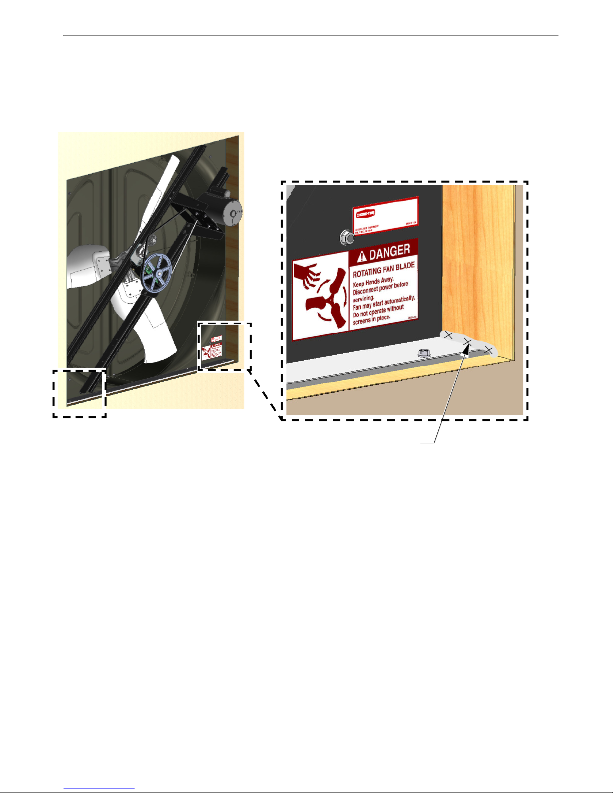
Danger Decal is located in Bottom
Right corner of the Shroud.
Exhaust Side Down
Top of Fan Shroud
Installation
Inspecting the Shroud (For assembled versions skip to page 12)
Inspect the Shroud assembly for hardware as received.
Fan Shroud Assembly (Unassembled version)
Rest Fan Shroud on Saw Horses for ease of Assembly
MV2406P
7

Installation 57" Endura
®
Fan
8
MV2406P
Attaching Fan Posts
(46764) x3
Nut
(53204)
Fan Post
Decal
(46764) x3
Nut
(27868-1) x3
Bolt
(53039)
Cone Bracket
(53206) Bottom Corner
Support Bracket
One Notch
1st Hole
View from Front of Fan
(bottom left corner)
Hardware Full Scale
2nd Hole
Two Notches
(53205) Top Corner
Support Bracket
(53039)
Cone Bracket
(53204)
Fan Post
(27868-1) x3
Bolt
(54287) 5/16-18 x 1.00
SS Shldr. Bolt
(46764) 5/16 Flg. Nut

57" Endura
®
Fan Installation
MV2406P
9
Cone Brackets, Corner Brackets (Corners without Posts)
(46764) Nut
(53205)Top
Corner Sup-
port Bracket
(27868-1)
Bolt
(53039)
Cone Bracket
Two Notches
1st Hole
2nd Hole
One Notch
(53039)
Cone Bracket
(27868-1) Bolt
(53206) Bottom
Corner Support
Bracket
(46764)
Nut
(54287) 5/16-18 x 1.00
SS Shldr. Bolt
(46764) 5/16 Flg. Nut
Hardware Full Scale

Installation 57" Endura® Fan
Apply a Fan Description Decal to the Shroud
as shown
. (Included in Parts Package)
(53753-X)
(46764)
Drive Assembly
(46764)
(48396C) Motor Support
(54287) x8
(54287) 5/16-18 x 1.00
SS Shldr. Bolt
(46764) 5/16 Flg. Nut
Hardware Full Scale
Use the Bottom Set of Holes in the
Posts as shown.
Installing the Drive Assembly and Motor Mount
10
MV2406P

57" Endura® Fan Installation
(53037)
Top Pivot Plate
(46764) Nut
(3066) Eyebolt
(53036) Bottom Pivot Plate
(46764) Nut
(46764)
Nut
Insert (53399) Door Stop Cable
Assembly into Top Pivot Plate
(46764) 5/16 Flg. Nut
Hardware Full Scale
Pivot Plate Tab
Centered in V-Post
V-Post
Pivot Plate Tab
Centered in V-Post
V-Post
Top and Bottom Pivot Plates and Eyebolt, Door Stop Cable
MV2406P
11

Installation 57" Endura® Fan
SS 1/4-10 x 1-1/2" Lag Screws
Tighten until Snug only. Do not
Deform the Bottom Shelf.)
(41561)
(41561) 1/4 x 1-1/2 Lag Screw
Center of Rough
Opening
Outside of House
(53338)
Bottom
Shelf
Center of Bottom
Shelf
If the Shelf is too long Trim
equal amounts from both ends.
This Flange must not be
bowed after installation!
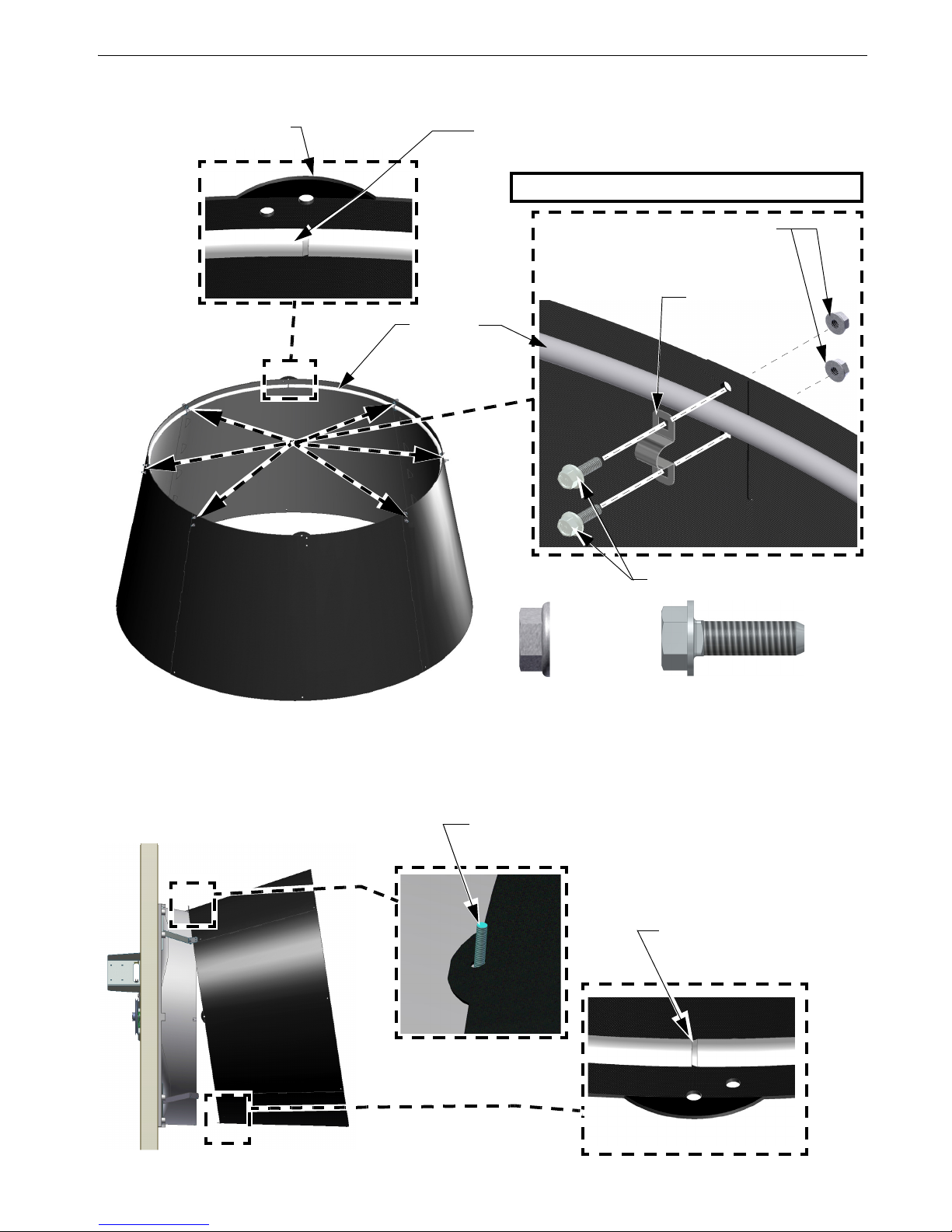
Eyebolt indicates the Top of
the Fan.
Line up the four Holes in the
Shroud with the Holes in the
Bottom Shelf.
Set Fan Shroud on the
Bottom Shelf.
Bottom Shelf Installation
Attaching the Fan to the Wall
12
MV2406P

57" Endura® Fan Installation
It is important when attaching the Fan to the Wall to keep edges of Shroud straight.
5
5
(41561)
(41561)
Pre-drill holes to 3/16" [4.8 mm] to
avoid splitting lumber. If holes do not
line up with the lumber it may be necessary to put Screws through Shroud.
Important! Attach the Fan to the
Wall with 1/4 x 1-1/2" Lag Screws
(41561) in the specific order shown.
Attach with a total of 20 Lag Screws.
5
5
4
1
3
A 600 Lb. Hand Clamp can be used
to straighten Shroud if necessary.
Keep edges of Shroud Straight
2
Use the Hole in the Corner Bracket that is
centered with Lumber to avoid splitting.
(41561) 1/4 x 1-1/2 Lag Screw
MV2406P
13

Installation 57" Endura® Fan
Assemble Cone Panels as shown below.
Two Holes
Prop the Cone
Panels up off
the ground to
ease assembly
One Hole
Tabs Up
Tabs Snap positively
in place
Cone Assembly
14
MV2406P
57" Endura® Fan Installation
(46764)
(54287)
Rounded Tab on the Cone
Orifice Frame Shown Gray for Clarity.
Important! Line up the Seam in the Orifice Frame
with one of the rounded Tabs on the Cone.
(53416)
Orifice
Frame
(53611)
Frame
Bracket
(54287) 5/16-18 x 1.00
SS Shldr. Bolt
(46764) 5/16 Flg. Nut
Hang the Cone on the Eye-Bolt extruding from the top of the Shroud using the hole in
the Cone as shown.
(30663) Eyebolt
Seam in Orifice Frame
Installing the Orifice Frame
Cone Installation
MV2406P
15

Installation 57" Endura® Fan
Attach the cone to the Shroud as shown below.
Use the Bolts in the Cone to attach the Cone to
the Cone Brackets. Use the Bottom set of holes
in the Cone Brackets.
If necessary, slip a thin piece of metal between
the Shroud and Cone and work it around the
Cone to get it on.
Slip the Orifice Frame behind the Bottom Pivot Plate.
Bottom Pivot
Plate
5/16 Flg. Nut (46764)
5/16 Flg. Nut (46764) (46764) 5/16 Flg. Nut
16
MV2406P

57" Endura® Fan Installation
Insert Door Pins in both Doors as shown.
Push Pins in until they bottom out.
Doors are Left and Right specific.
Insert Door Pins into Bottom
Pivot Plate.
Grab the Door in the Center, Bow the Door outward,
and insert the Top Door Pin into the Top Pivot Bracket
as shown. Do not Overbow the Doors!
(53038) Door Pin
Door
Top Pivot Plate
Bottom Pivot Plate
Door Pin
Spring
Holes in
Doors
View of Back of Door View of Back of Door
(53038) Door Pin
Door Assembly and Installation
MV2406P
17

Installation 57" Endura® Fan
Install the Fan Cone Grill (as shown). Attach the end of the Door Stop Cable to the bottom Grill Leg as shown.
(54287)
(46764)
If it is desired to Mount Fans at the minimum spacing cutting the Grills is required as
shown.
(46764)
(ST99070)
(46764)
(54287)
Door Stop
Cable
Door Stop Cable
even with the
edge of Cone
(ST99070)|
3/8 SS Flat Washer
(46764)
5/16 Flg. Nut
(54287)
5/16-18 x 1.00 Bolt
Cut the Grill here
Push the Cone Side
in and use a Clamp to
secure the Grill
Wires.
(732) Clamp (In Parts Package)
Grill Installation
18
MV2406P

57" Endura
®
Fan Installation
MV2406P
19
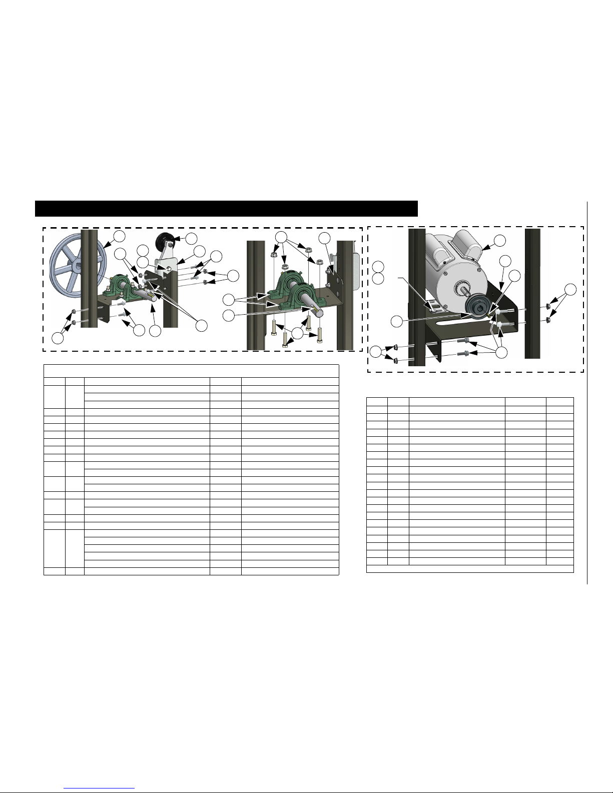
Rotate Motor Support (Assembled Fans)
Rotate the Motor Support Bracket into the upright position by removing the
upper Bolt and Nut, and loosening the lower Bolt and Nut.
Attach the Motor Support Bracket to the Posts with
5/16 Bolts (54287) and 5/16 Flange Nuts (46764).
Remove Bolt
4x (54287) 5/16-18 x 1.00
SS Shldr. Bolt
4x (46764) 5/16 Flg. Nut
Loosen Bolt
(46764)
5/16 Flg. Nut
(54287)
5/16-18 x 1.00 SS Shldr. Bolt

Installation 57" Endura® Fan
Attach Motor to Z-Bracket.
Motor
(54287)
Torque Set Screw to 150-165 IN-LBS
[16.9-18.6 NM]
Motor
Anti-Seize
Motor
Sheave
3/16" Key Supplied (Taped to Motor)
Center the Sheave with the
Hole in the Z-Bracket
(54287) 5/16-18 x 1.00 SS
Shldr. Bolt
(46764)
5/16 Flg. Nut
Z-Bracket
(46764)
Motor Installation
20
MV2406P

57" Endura® Fan Installation
Blade Installation
Motor Sheave
Tensioner Pulley
Belt
Driven Sheave
Fan Blade Part
Number
Push
Anti-Seize
Blade
1/4" Key
Torque Blade Set
Screws to 150 - 160 IN
[16.9-18.1 NM] LBS.
Fan Blade Flush with
the End of Shaft.
Belt Installation
MV2406P
21

Installation 57" Endura® Fan
Spin the Blade by hand and check that there is
minimum of 1/8" [3 mm] Clearance from the
Shroud all the way around orifice.
If Clearance is insufficient, check that the
mounting surface is flat, and that the sides of
the Shroud are straight. To Gain more Tip
Clearance, remove the Lag Screws from the
side with inadequate clearance, push out on the
Shroud orifice. (Push only on the inner most
2" [5.08 cm]of the Shroud or damage could
occur) Re-install Lag Screws in new holes.
Push only on inner most
2" [5.08 cm] of Shroud
1/8" [3mm] Minimum
Door Springs
Rounded end of Springs attached to Eyehook
Elongated end of Spring
attached to Door Hole
Door Spring Installation
22
MV2406P
57" Endura® Fan Installation
Caulk both Ends of the Bottom Shelf and as needed to fill any gaps between the Shroud
and the Framed opening.
Caulk Both Ends of the Bottom Shelf
Caulking
MV2406P
23

Installation 57" Endura® Fan
1. Check that the electrical power
being supplied to the Fan
matches the electrical Specifications on the Fan and Motor
Decals.
2. Remove the Motor Access
Cover.
3. Install an electrical disconnect
within reach of each Fan
installed.
4. Connect the cord to the motor
according to the wiring diagram
on the motor. Verify that the
motor is connected for counter
clockwise rotation (viewing the
back of the motor, opposite the
shaft end.)
5. Follow local, state, and national
electrical codes for wiring.
6. Attach the Cord to the Wall using
a Screwhook as shown. Allow
enough slack in the cord to form
a "drip loop" for moisture to fall
away from the cord and not into
the motor.
Screwhook
Motor Access Cover
Drip Loop
Motor Wiring
24
MV2406P

57" Endura® Fan Installation
2. Install a spring (54480) in the
upper left corner following
steps A through D below. After
Step D is complete go to step 3.
A) Slide a Spring (54480)
over both Screen Panel Wires
exactly as shown.
B) Rotate the Spring CounterClockwise until the end of the
Spring snaps over the Side Panel
Wire.
C) Slide and Pull Spring over
Corner Panel Wire.
D) Twist Spring Clockwise until it is passed
the outside wire and snapped firmly in place.
1. Fold the Screen Sides as shown.
3. Rotate the Screen in the direction
shown installing a Spring at a second
corner. Repeat for remaining Corners.
Pull
Install Spring
per steps A-D
below.
Install a Spring
at each corner.
Adjust Screen Panels so
they are as even as possible
Spring snapped firmly
between wires.
Corner Wire
Slide
Snapped over Side Panel Wire
Screen Assembly
MV2406P
25

Screen Installation
3/4" [1.9cm]
14" [35.6cm]
[71cm]
28"
3/4" [1.9cm]
3/4" [1.9cm]
1" [2.5cm]
3/4"
[1.9cm]
1" [2.5cm]
3/4"
[1.9cm]
[71cm]
28"
14" [35.6cm]
3/8" [1cm]
Depth of
all Screwhooks
3/4" [1.9cm]
Screen Installation 57" Endura® Fan
Continued on next page.....
26
MV2406P

57" Endura® Fan Screen Installation Continued
.
Motor Cord
Hang Screen on Top Screwhooks
Screen Rests on Side
Screwhooks as shown.
Screen Installation Continued
MV2406P
27

Test Fan for proper operation. 57" Endura® Fan
1747-054 04/03
Bad Belt (Needs Replaced)
Bad BeltGood Belt
Tensioner
Tensioner Base
Alignment Mark
1st Line
Idler Support Bracket
1747-053 04/03
Bad Sheave (Needs Replaced)
Good Sheave
Bad Sheave
Test Fan for proper operation.
Plug the Fan in and test for proper operation
Maintenance
IMPORTANT! Disconnect Power Prior To Maintaining Or Cleaning The Fan. The fan may start automatically causing
serious injury or death.
• Service and repair of fans should be done only by a qualified technician.
• Minimize contact of moisture or corrosive chemicals to the surfaces of the fan components to maximize fan life.
• After washing fans, operate fans long enough to remove moisture from all fan surfaces.
• Keep the fan clean for maximum life and best performance. Do Not spray water on the Fan Shaft Bearings, the Belt
Tensioner, or the Motor.
• Periodically check the V-Belt and replace if necessary. A worn Belt will cause a substantial drop in Fan performance or
it can break and cause Fan failure. If a Belt rides below the Sheave edge, replace the belt. (See below)
• Check Belt Tension. The Belt should be tensioned just tight enough to minimize Belt
slippage. Over tensioning the belt will cause
premature Belt and Bearing wear.
• The Alignment Mark on the Tensioner Base
should be lined up with the 1st line on the
Idler Support Bracket.
• Check Sheaves for wear. Replace if a Sheave groove is worn.
28
MV2406P

57" Endura® Fan Maintenance
Note: Some Parts removed for Clarity
Grease Zerk
Grease Zerk
Fan Bearing and Belt Tensioner Lubrication
• Grease zerks are provided for lubrication on the fan shaft bearings and the belt tensioner.
• Lubricate the fan every 2-6 months or whenever these components get wet.
• Disconnect power to the fan before lubricating.
• Clean the zerk before lubricating to prevent contamination from entering the bearing.
• Use a high quality lithium based, NLGI #2, grease such as Shell Gadus S2 V100 2. Do not use incompatible greases
containing aluminum, barium, calcium, bentonite clay or polyurea thickeners.
• Slowly rotate the fan shaft by hand while slowly applying the grease. Rapidly applying grease to a stationary bearing
can damage the bearing seals.
• Apply about .10 oz (2.8 g, 3.1 cc) of grease at a time or until a slight amount of grease can be seen purging from the
seal.
MV2406P
29

Part Numbers (Itemized) 57" Endura
®
Fan
30
MV2406P
Part Numbers (Itemized)
25
6
15
17
x4
26
31
32
32
32
41
46
51
2
47
42
55
40
40
7
56
*
1
31
48
8
49
11
One Notch
Two Notches
Detail "B"
Detail "A"
50
57" Endura
®
Fan Part Numbers
MV2406P
31
Part Numbers
57" Endura
®
Fan Part Numbers 53464-XX, -XXS
Item Qty. Description Part No. Models
1 1 Motor, 1.5H 1PH-60HZ-230V 49903 -22, -22S, -23
Motor, 1.5H 3PH-60/50HZ-200/380-460V 48608 -41,-42,-51,-52,-41S,-42S,-51S,-52S
Motor, 1.5H 1PH-60HZ-230V 50496 -21,-21S
2 2 57" Fan Post 53204 All
3 2 1" Pillow Block Bearing 50553 All
4 1 Idler Drive Bearing Support 48395C All
5 1 Idler Drive Motor Support 48396C All
*6 1 57" Fan Shroud Assembly 52925 All
7 2 Upper Corner Support (2 Notches) 53205 All
8 2 Lower Corner Support (1 Notch) 53206 All
9 1 AFD99100 Composite Sheave 54118 -21,-22,-41,-42,-21S,-22S,-41S,-42S
AK94 x 1.00" Bore Driven Sheave 40274 -51,-52,-51S,-52S
10 1 AK30 3" O.D. x 5/8 Bore Motor Sheave 8773 -21,-22,-41,-42
AK34 37919 -51,-52
11 1 AX60 V-Belt 48541 All
12 1 1" x 11.97" Fan Shaft 52083 -21,-22,-41,-42,-51,-52
1" x 11.97 SS Fan Shaft 54438 -21S,-22S,-41S,-42S,-51S,-52S
13 1 Tensioner Support 49737 All
14 1 Tensioner Assembly 3.5" Arm 3" Dia. 48429 All
15 1 57" Galv. High Capacity Fan Blade 53219 -21,-41,-51
57" Galv. E. Efficiency Fan Blade 53532 -22,-42,-52
57" High Capacity SS Fan Blade 54529 -21S,-41S,-51S
57" E. Efficiency SS Fan Blade 54530 -22S,-42S,-52S
57" Galv. Min. Vent Fan Blade 56108 -23
16 2 1/4" Sq. 1.13" Key 2419-2 All
Item Qty. Description Part No. Models
17 4 Cone Bracket 53039 All
25 1 57" Fan Support Shelf 53338 All
26 1 56 x 56 x 12.35 Inlet Screen 48794 All
31 42 5/16-18 x 1 SS Shoulder Bolt 54287 All
32 57 5/16-18 Hx. Serrated SS Flange Nut 46764 All
33 4 3/8-16 x 1.50 SS HH Bolt 4413-10 All
34 4 3/8-16 SS Serrated Flange Nut 50191 All
35 1 3/8-16 x .75 SS Hx. Bolt ST99277 All
36 1 3/8 SS Lock Washer ST99780 All
40 24 1/4-10 x 1-1/2 Lag Screw SS 41561 All
41 9 Open Eye Hook 1214 All
42 1 Fan Decal 39002-XXX All
46 4 .125 x .50 Magnet 48427 All
47 8 Magnet Side Plate 53026 All
*48 1 57" Fan Cross Rod 53398 All
*49 2 57" Fan Cross Rod Coupler (Rivet) 56339 All
50 2 1/8 x .40 Countersunk SS Pop Rivet 48936 All
*51 1 57" Center V-Post 53626 All
55 1 Screen Spring (Package of 4) 54480-4 All
*56 2 Fan Danger Decal 2527-50 All
57 1 3/16 x 1-3/8 Key (w/motor) -- All
* Fan Shroud Assembly (Item 6) Includes items 48,49,50,51, and 56
9
12
13
14
32
33
32
32
x4
1
10
Detail "A" (From previous page)
31
32
31
31
36
35
31
5
32
34
3
4
16
31
32
57
Detail "B" (From previous page)

Part Numbers Itemized (Continued) 57" Endura
®
Fan
32
MV2406P
Part Numbers Itemized (Continued)
18
20
x4
22
24
27
28
30
32
32
31
32
29
32
32
39
52
32
31
53
21
32
37
**
32
31
23
29
19

57" Endura
®
Fan Part Numbers (Continued)
MV2406P
33
Part Numbers (Continued)
57" Endura
®
Fan Part Numbers 53464-XX, or 53464-XX,XXS
Item Qty. Description Part No. Models
18 1 Orifice Frame 53416 All
19 6 Orifice Frame Bracket 53611 All
20 4 57" Cone Panel 53163 All
21 1 Top Pivot Plate 53037 All
22 1 Bottom Pivot Plate 53036 All
23 1 Ø1/2" x 11" Door Spring 49629 All
24 1 72.5" Fan Cone Cable 53399 All
27** 1 Left 57" Door Assembly 52926L All
28** 1 Right 57" Door Assembly 52926R All
29 4 1/4 x 1-3/4 420 SS Spring Pin 53038 All
30 1 70" Cone Grill 53129 All
31 42 5/16-18 x 1 HXWH SS Shoulder Bolt 54287 All
32 57 5/16-18 Hx. Serrated Flange Nut 46764 All
37 2 3/8 SS Flat Washer ST99070 All
39 1 5/16-18 x 2 SS Eye Bolt 30663 All
52 4 Striker Plate 53027 All
53 2 Cable Clamp 732 All
54 1/3 Anti-Seize (Not Shown) 47749 All
**Doors Include 53027 Striker Plates (Item 52)

Part Numbers (Continued) 57" Endura® Fan
Made to work.
Built to last.
®
Revisions to this Manual
Page No. Description of Change ECO
34 Updated Contact Info 33817
11 Added Pivot Plate Tab Detail
30,31 Item 50 was (7791-3) 1/4-20 x 1/2 Press Stud
30,31 Item 49 was 53896
For additional parts and information, contact your nearest Chore-Time distributor or representative.
Find your nearest distributor at: www.choretime.com/contacts
34
Chore-Time Group, A division of CTB, Inc.
PO Box 2000
Milford, Indiana 46542-2000 USA
Phone (574) 658-4101 Fax (877) 730-8825
Email: choretime@choretime.com
Internet: www.choretime.com
MV2406P
 Loading...