

Page 1

WIRE CUT- EDM
Operation Manual
SOFTWARE VERSION:W5F F0800
MANUAL VER:
B
Copyright Reserved
CHING HUNG MACHINERY & ELECTRIC INDUSTRIAL CO., LTD.
886-4-23500333
Please Read This Manual Thoroughly Before Operation
Page 2

Please Read This Manual Thoroughly Before Operation
Thank you for buying our product, and for the chances of being able to offer you
our high quality wire EDM series machinery and also the best after-sale services.
In order to maintain machine’s peak performance and extend its lif e span as long
as possible, we sincerely suggest all the operators carefully read this manual for
first time operation. Also, for your safety, please read the following “mustknown” precautions:
1. Wire EDM operators should have received relative tr aining from our
local agency, or dir ectly from CHMER headquarter.
2. CHMER wire EDM can only applied to the machining of several kinds
metal work-piece, such as steel, aluminum, tungsten steel, copper and
of
graphite.
3. Push emergent switch before executing any one of following tasks:
(1). Cleaning or sorting waste wire.
(2) Replacing resin or paper f ilte r.
(3) Filling up water tank.
(4) Opening power cabinet.
4. Push emergent switch and turn off r otary switch immediately when any
one of the following situations occurs.
(1) Hearing of funny noise, or any abnormality occurs during
machining.
(2) Unloading any ma chine’s power wire (in power cabinet, water
tank, or cooling machine .). Please contact our local agency first,
or CHMER headquarter for this.
5. To avoid dangerous shock, be sure to stop electricity discharging before
installing copper wire and work-piece.
6. Do not touch any part around worktable (upper/lower head, wire and
water) during m a chining to prevent from high voltage str ike.
7. Do not modify ele ctrical circuit.
8. Please take reference to relative chapter in this manual for daily
maintenance.
9. Please keep this manual closely with the machine .
Thank you again for purchasing CHMER’s product. Please call our Service
Department at 886-4-23500979 anytime for technical support and repair.
It is our honor to be at your service…
Page 3

INDEX
0-1
Company Profile--------------------------------------------------
0-2
Safe Instruction---------------------------------------------------
Chapter 1.
System Introduction
1-1
System Composition---------------------------------------------
1-2
Panel & Keyboard------------------------------------------------
1-3
Machine Body & Filtration Unit-------------------------------
1-4
System Boot Up and Shut O ff----------------------------------
Chapter 2.
W5F Software Function
2-0
Map of W5F Softwar e
2-1
DISP Mode--------------------------------------------------------
2-2
FILE Mode--------------------------------------------------------
2-3
AUTO Mode------------------------------------------------------
2-4
MAN Mode-------------------------------------------------------
2-5
DATA Mode-------------------------------------------------------
2-6
HELP Mode-------------------------------------------------------
Chapter 3
Application of G, M code
3-1
G Code Illustration-----------------------------------------------
3-2
Usage Description of G Code-----------------------------------
3-3
Auxiliary function (M Code)------------------------------------
3-4
G, M Code Comparis on with Others---------------------------
Chapter 4
Appendix
4-1
Consumable List--------------------------------------------------
4-2
Shield Room-------------------------------------------------------
4-3
Precaution for Malfunction--------------------------------------
4-4
Setup of Remote Monitoring Software ------------------------
4-5
Lower Head Disassembled and Assembled-------------------
4-6
Upper Head Disassem bled and Assembled-------------------
0-1
0-5
1-1
1-2
1-16
1-21
2-1
2-10
2-57
2-85
2-126
2-136
VER: E5B-1087B
3-1
3-7
3-42
3-47
4-1
4-5
4-9
4-11
4-15
4-18
DATE: 2012.01
EDITOR: Eirene Wu
Page 4

CHMER Wire-Cut EDM Operation Manual W5F
Taiwan.
2.1976
The first hydraulic co ntrol EDM machine came out.
e functions of free adj ustment of pulse on & of f
was produce d.
4.1979
Moving to the new factor y for developing southeast-Asia market.
5.1980
Leading to export EDM machine made in Taiwan to Europe.
domestic market.
standard bur eau of the re public of Ch ina.
the governm ent.
orbit-cut was produced.
In July , the first EDM machine with the finest and super finish device
of U-SPARK In Taiwan was produced.
◆In August, Sound Best Trading Co., Ltd Establis hed.
◆In September, Hung Yu Trading Co., L td Established.
10.1986
In February, Ching Yeng Machine & Electric Co., Ltd Established.
marketed.
the excellent-product design award from CETRA of Taiwan, ROC
12.1988
In August, small hole drilling EDM was completed.
business – f ounding youth for the 11th term.
13.1989
In March, the giant bridge type of EDM was created.
available for modifying to sparking conditions during machining.
◆In Jun, Chiao Yeng Machine Co., Ltd. Established.
◆In Jun, Hwang Long Machinery Industrial Co., Ltd. Established.
giant bridge type of ED M (NEW MODEL NO.58428)
0-1 Company Profile
CHMER BRIEF EVENTS:
1.1975 ◆CHMER EDM company was founded(with registered ca pital
NT$200.000.-)to marke t the first“Transistor”
◆
3.1977 ◆EDM machine with th
EDM mac hine in
◆
◆
6.1981 ◆Su pplying the first EDM w ith P.W.M. servo motor driver to the
7.1982 ◆Ac hie vi ng tw o pat ent s for the new squ a re axes wi th na ti ona l cen tr a l
8.1983 ◆The first EDM manufacturer obtaining“Golden dragon award”form
9.1985 ◆In A pril, the first multifu nctional CNC EDM machine equipped with
◆
◆
11.1987 ◆In July, the first EDM mac hine without ba cklash on x & y axes was
◆In April, the WIRE-CUT EDM machine was completed and obtained
◆
◆In December, President Wang was honor ed with the model of
◆
◆In April, marketing new type of CNC EDM which interfale wa s
14.1990 ◆ In October, obtaining the patent for structure improvement of the
0-1
Page 5

CHMER Wire-Cut EDM Operation Manual W5F
bridge type of EDM(NEW MODEL NO.68192
tank ascen ding & descending(NEW MODEL NO.74419).
16.1992
In September, capital increased up to N T$50.000.000.-
technology.
In Sep, Hang Zhou Ruipeng Machinery & electric Co., Ltd Established.
In January, NC EDM with programmable Z axis, model CM240Z+50NZ,
from CET RA in Taiwan.
In March, Sound Best Automaticalization Industry Co., Ltd Established.
In December, Yukon CNC Machinery Co., Ltd. Established.
EDM manufactur er, in T aiw an, obta in i ng ce r tif ica te of
Economic A ffairs.
OF TAICHUNG, TAIWAN.
County Gove rn.
TAIWAN”.
directive 89/392/EEC “FROM NOTIFY BOY”
AMTRI VERITAS LTD. certificate number:AV EC 1105(G).
CM855C+75NC, CM645C+ 75NC achieved excellent products award of
again.
“THE INTERNATIONAL GOLDEN GLOBE AWARD FOR
15.1991 ◆In October, the patent for improvement structure of the worktable guide
◆Obtaining the patent for improved structure of the Prototype of EDM
17.1993 ◆In October, moving to the new factory with air—conditioning syste m to
◆
enlarge production covering digital products of high-scientific
)
◆
18.1994 ◆
& CNC EDM with PC base controller, model CM240Z+50NC, achieved
excellent product award of “IT’S VERY WELL MADE IN TAIWAN”
◆
◆
19.1995 ◆In January the 1st
quality ass urance specified as ISO 9002 form the BCIO of Ministry of
◆In March, President Wang, received Award of “GOLDEN TALENT” as
“INVENTIVE ENTERPRISER” from INDUDTRY ASSOCIATION
◆In November, Honored as “MODEL OF INDUSTRY” form Taichung
◆In December, obtained “GRAND GRAGON CENTURY AWARD OF
20.1996 ◆In January, obtain Attest ation of conf ormity for technical file and
non-annex IV machinery with the requir ements of the machinery
◆
◆In February NC EDM with programmable Z axis, m odel
CM380Z+50NZ & CNC EDM with PC base controller , models
“IT’S VERY WELL MADE IN TAIEAN” from CETRA in Taiwan
◆In August, the pr oduc ts of wire-cut EDM, CNC EDM & NC EDM
WITH PROGRAMMABLE Z AXIS obtained
0-2
Page 6

CHMER Wire-Cut EDM Operation Manual W5F
EXCELLENT EXPORT PRODUCT MADE IN TAIWAN”.
TAIWAN”
WELL MADE IN TAIWAN”.
23. 1999
Obtain Rising Star Award and National Award.
24.2000
Enterprise s Professional Manager Award.
wealth” magazine.
EDM.
wealth” magazine.
In January, “CW432S” “A53C+75N” obta ined Award of “IT’S VERY
WELL MADE IN TAIWAN”
Version.
In January, “CM434Z+50EZ ” obtained Award of “IT’S VE RY W ELL
MADE IN T AIWAN”
◆Register i nto Emer ging stock market.
Enterprise Innovation Research Award﹞
Company” award.
VER Y WELL MADE IN TAIWAN” award.
is the 1st among EDM manufacture in Taiwan.
in Taiwa n.
“IT’S VERY WEEL MADE IN TAIEAN” award.
21.1997 ◆In Jan, CNC wire-cut EDM models CW 430F, CW430W, CW530F,
22.1998 ◆CNC Wire-cut EDM models CW640 obtained award of “IT’S VERY
Cw530W obtained award of “IT’S VERY WERY WELL MADE IN
◆
◆
◆The 67th of “Top 100 up growth backbone enterprises”. Statistics by “Common
25.2001 ◆Provide fist precisi on bridge CNC wire cut EDM & CNC powder
◆The 29
th
of “Top 100 potential enter prises” Statistic s by “Common
26.2002 ◆
◆In February, obtained certific ate of quality assurance of ISO 2000
27.2003 ◆
◆In Septembe r, “CM323Z+50EZ+OB-head obtained” ﹝Middle
◆In November, CHMER obtained “The Nest Innovation research
28.2004 ◆In January, “CW-32CF/S”wire-cut ED M model s ob ta ine d o f “I T’ S
◆In March, CHME R obtained IS O 14000 Quality system certified, w ho
◆In March, Intr oduce the 1st linear motor high precision wire-cut EDM
29.2005 ◆In January, “P42SL” high precision wir e-cut EDM model obtained of
0-3
Page 7

CHMER Wire-Cut EDM Operation Manual W5F
COMPANY ORGAIZATION
Taichung Headquarters:
1.CHING HUNG MACHINERY & ELECTRIC INDUSTRIAL CO.,LTD
No.3, Jing-Ke 1st Road, Nantun District, Taichung City 408, Taiwan
TEL:+886 4-23509188 FAX:+886 4-23509199
2.Taipei Branch office
HUNG YU TRADING CO.,L TD.
NO.13,Dec4.Chung Hsing Ed , San Chung City, Taiwan, R.O.C
TEL:02-2988-8668 F AX:02-2985-0850
3.Hang Zhou Factory
HANG ZHOU RUIPENG MACHINERY & ELECTRIC CO.,LTD.
No.25,Ningdong Road Xiaoshan Economic Techinical Development Zone
TEL:0571-8283-1032 FAX:0571-8283-2034
0-4
Page 8
0-2-1Machine stop
CHMER Wire-Cut EDM Operation Manual W5F
0-2 Safety Instruction
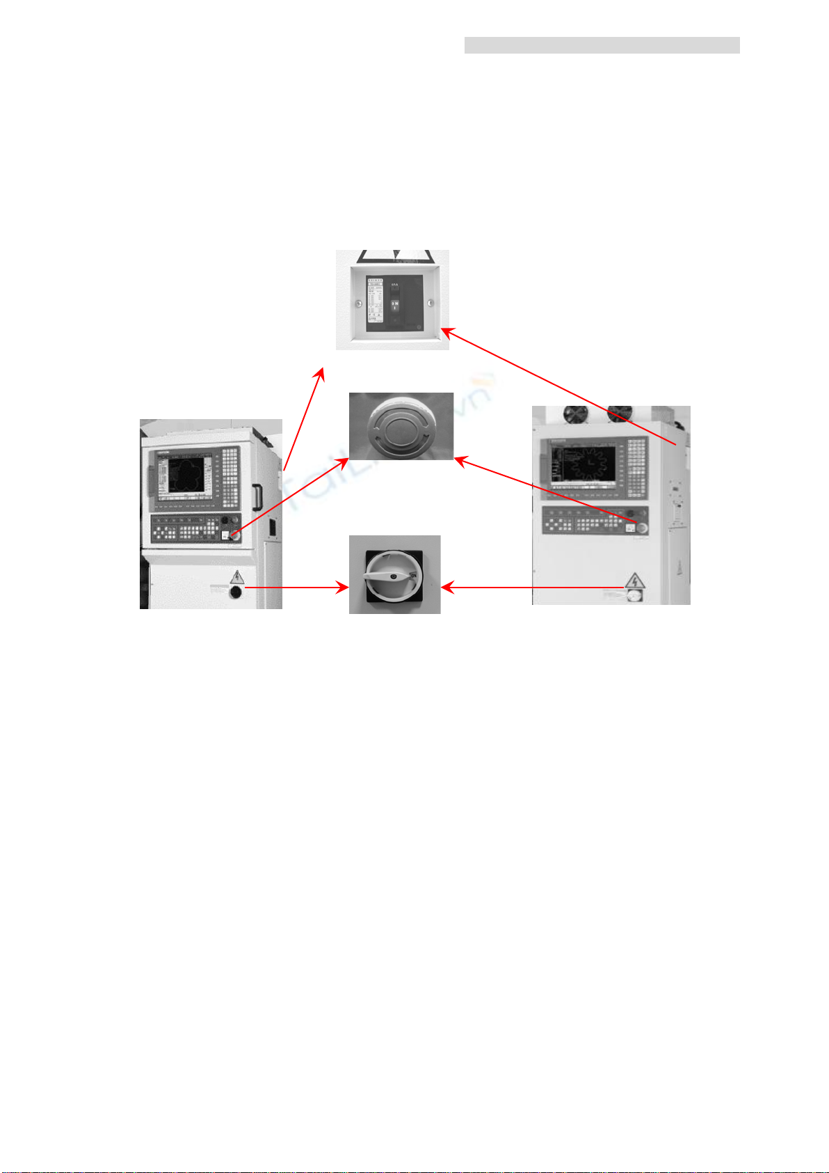
When the emergency occurs, operator can stop machine by following two ways:
Emergency Stop & Main P ower switch.
No Fuse Breaker
Emergency Stop
Main Power
Emergency Stop:Whe n pressed, except of com puter power, motors, pumps
would be shut off .
Main Power:Whe n turned off, the power of machine a nd Power Cabinet will
all be shut off.
No Fuse Br eaker:Be sure to turn off no fuse breake r and main power before
maintenance.
0-2-2 Precaution of safe operation
A safe operati on is re lying on complete preca u tio ns to occ a s iona l acc id ence,
machine bre akdown and operator negligence. Please keep these in mind a nd
check mac hine security every time before actual operation. Even though,
there are many built-in safety constructions in m a chin e, still po s s ible to hav e
potential dangers if de pends on ma chine too much and absent the precautio ns in
mind.
0-5
Page 9

0-2-3 Operation precautions
1. If find or smell or he ar any abnormal conditions, please pr ess emergency
stop button immediately then sta rt to locate the problem.
2. There will have fatal high vol tage high current passing through on duration.
Therefore, strictly prohibit touch anywhere is above water pan during
sparking.
3. There also will have electric power on traveling wire from wire spool to wire
waste box. Prohibit to a ny part s wire wi ll co nta c t dur ing sp a rk ing.
4. Keep away from XY axis and its metal co vers for potential finger-folding
injury at j ogging XY plane.
5. There always will have water on worktable & water pan. Don’t stand on it
anytime.
6. Screw well PE ground line s in powe r ca bi ne t an d elec tr ic al bo x es (on
machine column & water ta nk) for avoiding electric shock.
7. When power on wi ll start exhaustion fans. Don’t insert your fingers into fans
or its filter s.
CHMER Wire-Cut EDM Operation Manual W5F
8. Don’t open power cabinet doors (front door & rear door), doors of electrical
boxes or me tal covers of machine body for avoiding electric shocks.
9. When machi ne shut down, there still have electr ic power on capacitors.
Don’t touch it.
10. Don’t let water s plash on power cabinet or electrical boxes for avoiding
electric shock.
11. Stop machine immediately when finding out split/broken plastic coated of
electrode cables (connect between machine body & power cabinet) and,
don’t start machine before repa ir
12. Don’t dismount lines with E or PE marks grou nd lines to keep away of
electric shock.
13.On machine duration or after machining, there will have hi gher temperature
on work piece. Don’t touch it directly by hands.
14.Watch out of finger cut injury or, as put on work piece with sharp edge or
put on wire spool.
15.Please must shut dow n main power switch before opening po wer cabinet
doors or electrical boxes.
16. Please check and screw well fork pins on terminal blocks before powering
on. If any loosen pin and pow e r on, may cause unbalanc e power input,
motor noise, motor burning, terminal block burning.
17. Regarding t he waste materials like silt, lubrica ting, paper f ilters, used wire,
ion resin and broke n par ts ple a se take ove r with quality recy cle dea ler or
obey local deposition la w.
18. For taking care of water s plash out shall open upper / lower flushing knobs
from minimu m to maximum.
0-6
Page 10

CHMER Wire-Cut EDM Operation Manual W5F
19. Avoiding water splash on floor at any time, that has p otential dangers people
20. The light from the work-lamp could ge ne ra te high he a t on the items
fall down or get electric shock.
Safe operation and place for the personnel
1. Get rid of metal chips, water or oil i s onto around the machine.
illuminated. Please b e aware and keep fusible m a terial such as plastic
cables away from being irra di at ed by work-lamp.
2. Operator p ut s on s afe glas se s and saf e s ho es.
3. When move in/ move out the work piece from working table, watch out the
fall down risk.
Checking points for safe dielectric cutting
1.Ensure work piece is fixed well by proper jigs and fixture ways on working
table.
2.Wire electrode is lo adi n g and traveling well by instr uc ti on s.
3. Electrode cab le s / grou nd li ne s
a. Are they screwed properly?
b. Cable coating in good conditions without any split?
c. Upper/ lower nozzle distances are adjusted well w on’t crash to each
other
Precaution of the use of stainless steel
1.The im proper way of material cons ervation will shorten its life span.
Stainless steel tends to erode m or e rapidly after in touch with other m a terials.
2. The rust from other material could be passed to stainle ss steel if not properly
stored.
Checking points before cutting
1.Dielectric level is set properly (Submerged model)?
2. Is dielectric level drop ping down accidentally?
3. Is work tank loc ked properly (submer ge type)?.
4. Is Rubber Se al of tank door damaged?
Checking points while cutting
1. Make sure no leak age of die lec tr ic .
2. Upper/Lower flush pressure were adjusted to be coincident?
0-7
Page 11

3. Is Cutting technology well setup?
CHMER Wire-Cut EDM Operation Manual W5F
4. For no-man oper ation, ple ase make sure machine ca n achieve:
a. Smooth a nd r eliable cutting condition?
b. Constant and stable flush pressure?
c. Dielectric level (for submerge type) remains constant?
0-8
Page 12

■
1-1
■
1-2
■
1-16
■
1-21
Chapter 1.
System Introduction
1.1
System Composition
1.2 Panel & Keyboard
1.3 Machine Body & Filtration Unit
1.4 System Boot Up and Shut Off
Page 13
1-1 System Composition
CHMER Wire-Cut EDM Operation Manual W5F
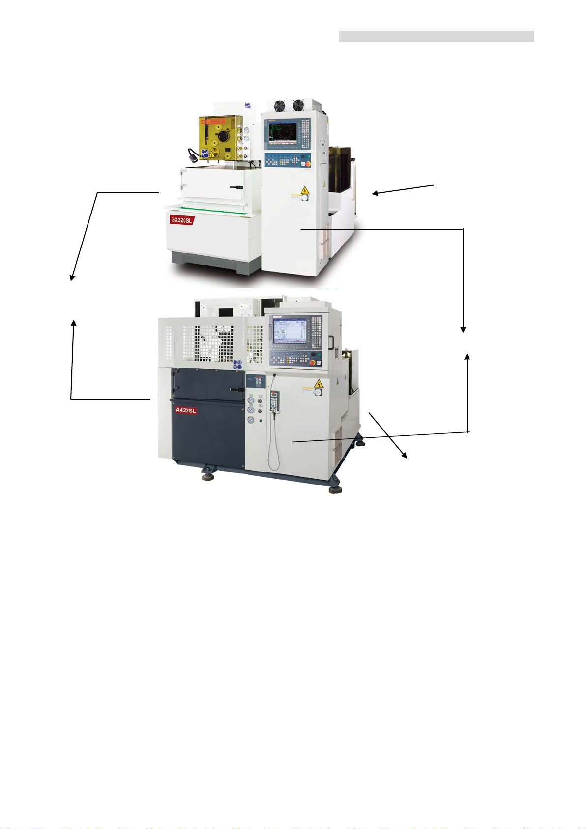
Filtration Unit
Machine Body
Power Cabinet
Filtration Unit
Wire Cut machine is consisted of three major parts:Power Cabinet, Machine Tool, and
Filtration Unit.
1. Power Cabinet
Contains majority of fuses, TFT LCD Display, Pow er Line, Computer and
Sparking Circuit.
2. Machine Tool
There are two types of Machine Tool: Submerge d and Flushing, which differed
from each ot her by whether equipped with (S) a stainless tank or not (F). For
example, CW 530S, CW 530F.
3. Filtration Unit
For dielectric filtration and de-ionization.
1-1
Page 14
CHMER Wire-Cut EDM Operation Manual W5F
Console Panel
5
Power Cabinet
10
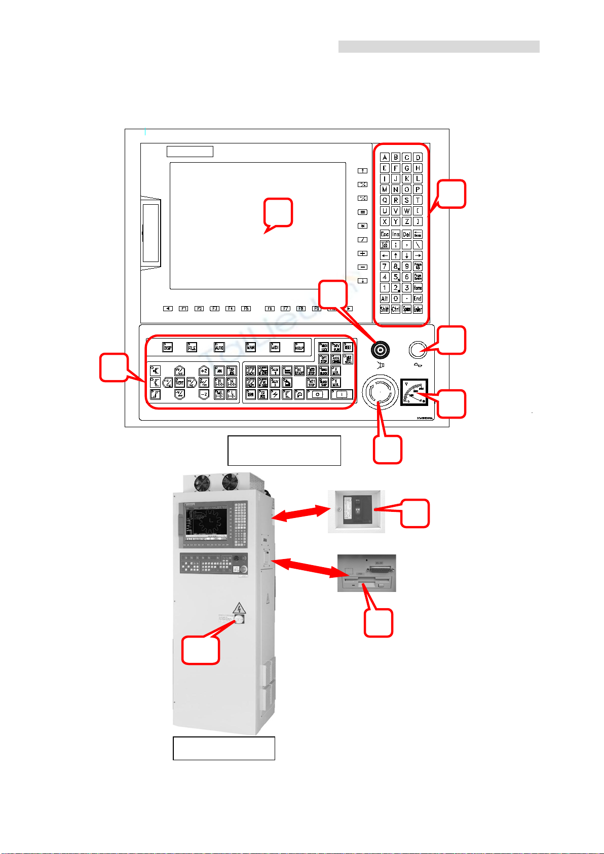
1-2 Power Cabinet, Console Panel and Remote Control
1-2-1 Power Cabinet & Console Panel
2
4
3
6
3
1
9
8
1-2
Page 15

1. Analog V oltage Meter
※
crosoft Mouse / Touch Screen
CHMER Wire-Cut EDM Operation Manual W5F
Display the variation of EDM voltage to control machining speed.
2. Monitor
15”(standard) TFT LCD monitor.
3. Contr ol panel
a. Text key: for norma l information and number input.
b. Hot key: control the EDM conditions. (e .g. EDM power supply, dielectric,
wire feed rate and tension)
c. Function key: system function execution.
4. Buzzer
Provide warning sound to remind the operator.
5. EMG-stop button
Under any situation, push this button will cut off power of the controller.
6. Main Power Switch
Main switch of the CNC controller.
7. Remote control
Contains basic hot ke y to opera te th e machine.
8. No Fuse Breaker
ON/OFF switch for electr ic current inflow and overload protection.
9. CF Card Drive/ USB Card Reader (Reserved for OPT)
Data storage interface of NC program from external computer. CF memory card or
USB for data storage.
10. CNC Power ON button
This button is for CNC controller power actuation. After switching on the main
electric power, push this button will actuate the CNC controller. Also, its power
indicator will be on at the same while .
Optional Functions (have to confirm controller’s version)
a. Mi
b. Memory CF Card capability
c. Installing in-house GENTEC Remote Monitoring software enables N.C. file
download /upload, watching on machining status f rom Client PC through
Internet
1-3
Page 16
1-2-2 Introduction of text keys
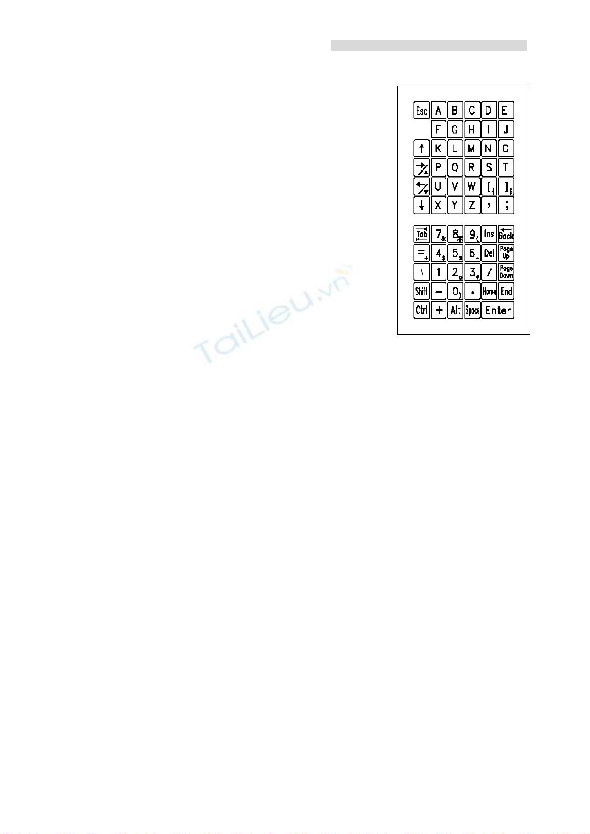
↑,↓
→,←
1. A~Z
Input key of English alphabet
2. 0~9
Number input
3. Page up, Page down
For page exchange (NC program or column)
4. Home, End
When execu ting program edit or data input, move
the cursor t o the left or right of the line.
5. Back
When executing program edit or data input , move the
cursor backwards and delete the original bit.
6. Space
Blank bit.
CHMER Wire-Cut EDM Operation Manual W5F
7. Enter
For data inp ut, function execution or lines addition during program editing.
8. Ins
Switch knob of character insert or replacement when editing pr ogram.
9. Del
When executing program edit or data input, dele te the character on the cursor
10.
For cursor movement or working data c hange when executing program edit or
data input.
11.
For cursor movement when e xec ut ing program edit or data inpu t .
12. +/-
Positive/negative marking of input data or increase/decrease of EDM data.
13. Esc
Cancel the input data.
1-4
Page 17
1-2-3 Introduction of quick func tion key
CHMER Wire-Cut EDM Operation Manual W5F
Operator could apply bel ow quick command:
1. Use +/- button to change the value of each item of sparking data.
2. Type S ???
(ex: S045) in Data Bar is to backup current sparking data to
S-code No. 045.
3. Type E ??? (ex: E045) in Data Bar is to call up existing spa rking data from
S-code No. 045 for use.
4. To reset Work Coordinate., type R in Data Bar t hen pr e s s ENTER.
5. To specify the value of each axis in Work Coordinate., type X??? Y???
Z??? U??? V??? in Data Bar then press ENTER . ??? is specified value.
6. To move axis incrementally, type MX??? MY??? MZ??? MU??? MV???
In Data Bar and press ENTER. M actually means M ove.
7. To move axis by specific Coordinate. System, type M#X??? M#Y???
M#Z??? M#U??? M#V??? in Data Bar and press ENTER. # (0:Machine
Coordinate. / 1:PGM / 2:G92 / 3:Work Coordinate.)
8. To move axis to reference point (G054~G959), type MG#5$X??? Y???
Z??? U??? V???.”# ranges from 0~9, and $ is from 4~9.
9. To move 1/2 distance of what mentioned fr om 6.~8., type MX/2, MY/2,
MU/2, MV/2.
10. In Data Bar, type GO and pr e ss ENTER , machine will move to the zero
points of the coordinate system wher e the cursor is currently on.
11. To execute N.C program from specific line, type N??? under
MEM\F1(MEM. PATH) when RESET button is lit on.
1-5
Page 18
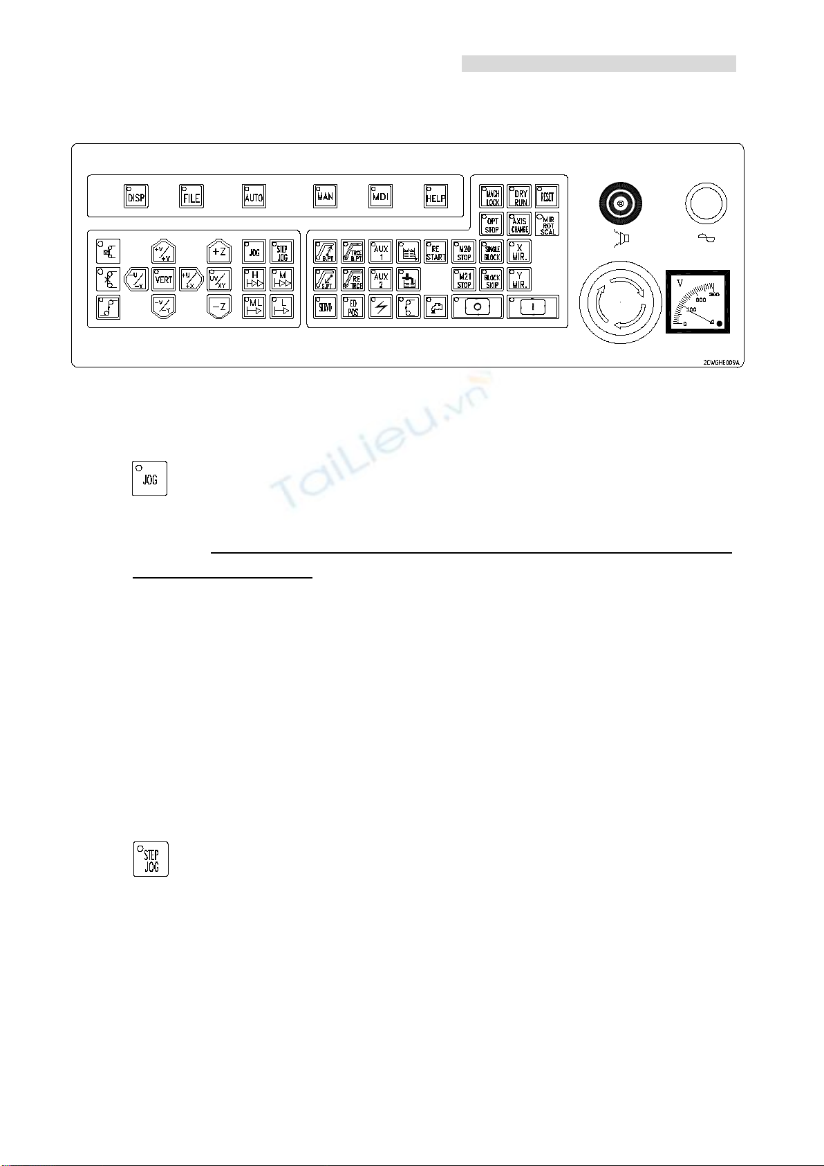
1-2-4 Introduction of operat ion key
2. STEP JOG
CHMER Wire-Cut EDM Operation Manual W5F
1. JOG
If this butt on is pressed, four kinds of table movi ng speed are selectable
including
H (high spe ed), M (middle speed), ML (spee d between middle and
low) and L (low speed). Under this mode, if the axis-moving key is pressed,
the table will move by setting speed. If it is releas ed, the table will stop
moving.
Note: 1. If the JOG b utton is pressed twice in 1 second, it will execute AUTO
mode.
2. The value of JOG feed-rate override may adjust in the mode Help-2
>「System Double Value Parameter」, PA#36~PA#41 (W e strongly
recommend user may not modi fy the value at will, other wise it may
cause unexpe cted damage to machine tool)
If this butt on is pressed, the table will move by set increment. The set
increments include H (1000µ), M (100µ ), ML (10µ) and L (1µ). Under thi s
mode, if the axis-moving ke y is pressed one time, the table will move 1
increment distance. If you want 2 increments move ment, press the axis-moving
key twice.
1-6
Page 19
CHMER Wire-Cut EDM Operation Manual W5F
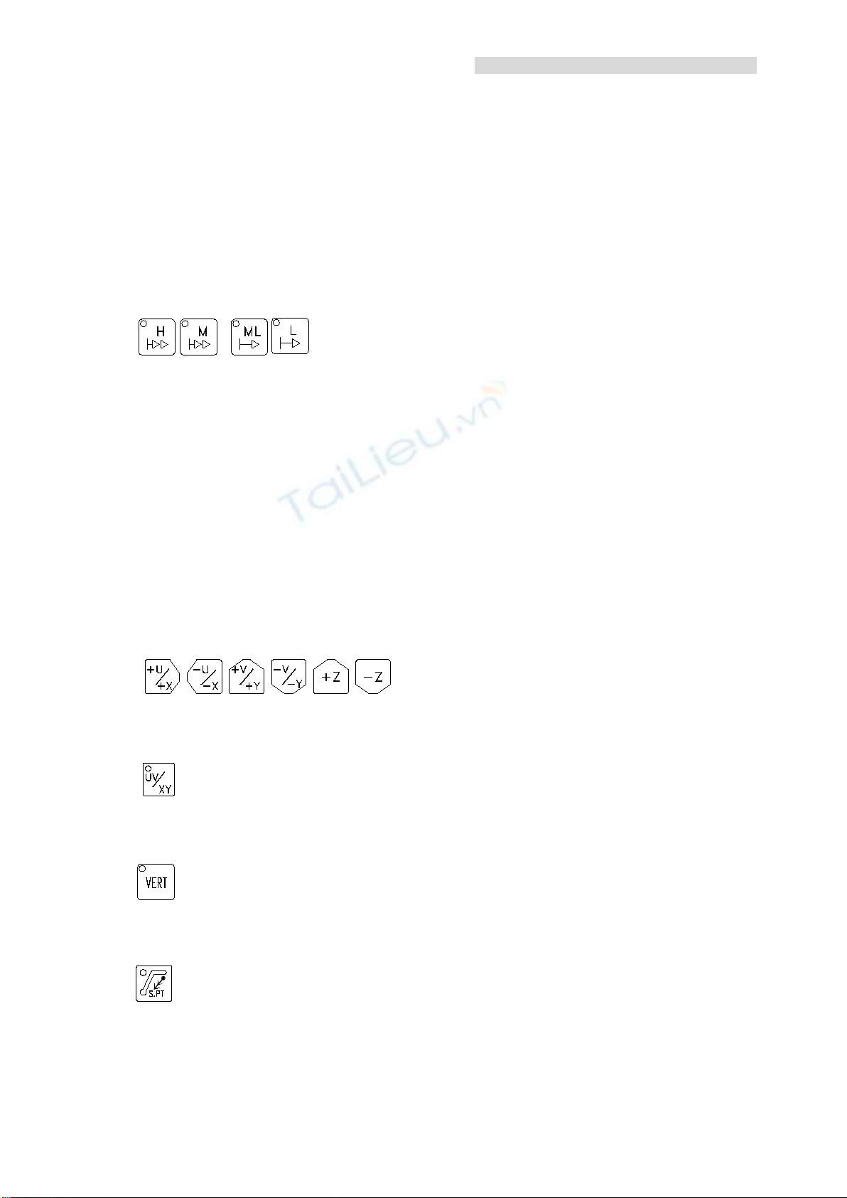
4.
+U/+X,-U/-X,+V/+Y,-V/-Y,+Z,-Z
Note: 1. Ad d it iona l ly increases the JOG spe e d to be 2 ste ps.
Setting method: Press H or M key twice in 1 second. F lash indicator
means that setting is finished.
2. The value of STEP JOG feed-rate override may adjust in the mode
Help-2>「System Double Value Parameter」, PA#42~PA#47 (We
3.
strongly recommend user may not m odify the value at will,
otherwise it may cause unexpected damage to machine tool.)
H, M, ML, L
These four k e ys are for speed setting under JOG mode. However, they are for
moving distance setting under STEP JOG mode.
Note: 1. Add it iona l ly increases the JOG spe e d to be 2 ste ps.
Setting method: Press H or M key twice in 1 second. F lash indicator
means that setting is finished.
2. The value of STEP JOG feed-rate override may adjust in the mode
Help-2>「System Double Value Parameter」, PA#42~PA#47 (We
strongly recommend user may not m odify the value at will,
otherwise it may cause unexpected damage to machine tool.)
These are axis direction keys. Under JOG or STEP JOG mode, they could
control the moving direc tion of the worktable.
5.
UV/XY
This is direction switch key. When the indicator is lit, it repr esents XY plane . On
the contrary, it becomes UV plane. (Parameter 68 bit 1)
6.
VERT
Press twice quickly, then worktable will return to ve rtical point; it ends up
when the LED lights on.
7.
S.PT
This key is f or start point quick return. When i t is pressed, the worktable will
return to start poi nt q uic k ly. If the indicator is lit, it repres en ts t h at the pr e sen t
position is the sta rt p oint.
1-7
Page 20
CHMER Wire-Cut EDM Operation Manual W5F
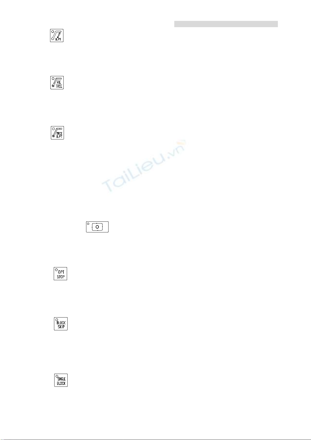
8. B.PT
This key is for br eak point quick return. When it is pressed, the worktable will
return to wir e break point quickly. If the indicator is lit, it represents that the
present position is the break point.
9.
RE-TRACE S.PT
This key is f or start point tracing. When it is presse d, the worktable will return
to wire break point t h en return to the start point alo n g the previous machin i ng
path at last. (Auto wire fe eding)
10.
TRACER B.PT
This key is f or break point tracing. When it is pressed, the worktable will return
to start point then re t urn t o the wire brea k po i nt alo n g the pre vi ou s m ac hini ng
path at last. (Auto wire fe eding)
Note. 1. Those four path trace functions #7~#10 can only be executed
one at a time.
2. The data of trace pat h according to the last G92 coordinate in processi ng.
3. While reboot the machine, it restore the last path data which had be en
stored.
4. Press
can interrupt during the trace function is activated.
5. User can start these four functions (pa th tra ce ) whe n ED M spa rk p ow er
is activated (Water flushing, wire feed, spark, ED -POS).
6. Auto wire feed would be ac tivate when execute those trace func tions.
11.
OPT STOP
This is for o ptional pause . When the in dicator is lit, if the program is execu ted
to M01, the machine will pause and systems of wa ter supply, w ire feeding an d
electric power are will be off. If the indicator is off, M01 will be ignored.
12.
BLOCK SKIP
This is for o ptional block skip. When the indic ator is lit, t he block inte r val
marked by “/” will be ignored. When the information is loaded from memory
to buffer area, the skip setting will be kept. This bottom is unavailable during
processing is activated.
13.
SINGLE BLOCK
This is for single block execution. When pressing this key during progra m
1-8
 Loading...