

Page 1
TECHNICAL MANUAL
942088.001
942088.001 - 24/09/98
1
TABLE OF CONTENTS
1.- INTRODUCTION 1
2.- EXTERNALS COMPONENTS 2
3.- BASIC OPERATION 4
4.- MAINTENANCE PROCEDURE 6
5.- ELECTRONIC BOARD OPERATION 7
1.- INTRODUCTION.
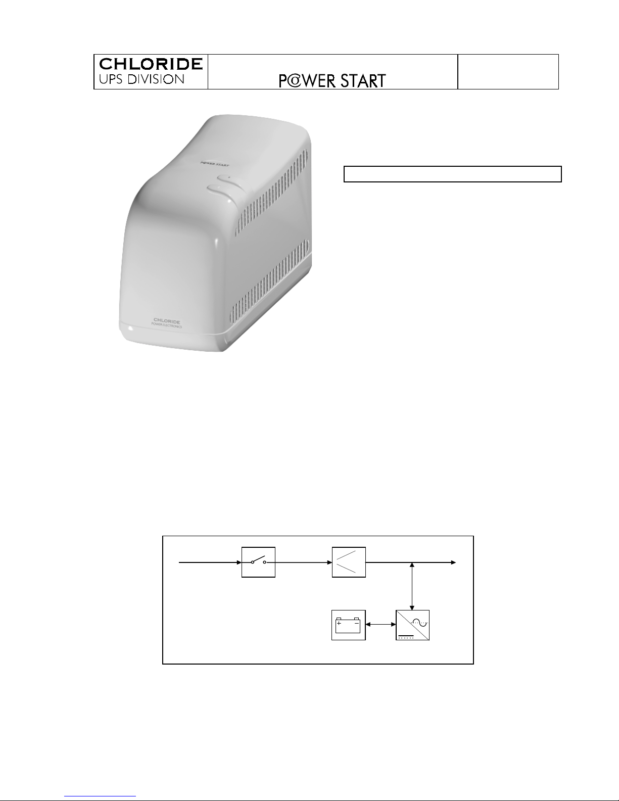
“POWER START” is a single phase line interactive UPS with booster. It is fully
microprocessor controlled with compu ter communication capabilities.
The power rates are 250VA - 400VA - 600VA for 230V 50Hz and 250VA - 400VA - 600VA
for 115V 60Hz all of them with cos ϕ = 0.6 (power factor).
It has automatic voltage regulation in two steeps, central and boost. The unit corrects the
low input voltage with the boost step.
The inverter is “PUSH-PULL” with “NULL”, based on MOSFET technology. The waveform is
regulated pseudosine when the unit operates on-battery.
The charger is based on a lineal regulator with full rectifier bridge.
AC
DC
BOOST
CONVERTER
BATTERY
IN
OUT
The boards’ code is 500152.XXX ( these codes can be changed in the future ).
REVISION NOTE : If any repair or modification affecting the revision of the equipment is
carried out, then this situation should be reflected on the identification sticker.
Page 2
TECHNICAL MANUAL
942088.001
942088.001 - 24/09/98
2
2.- EXTERNALS COMPONENTS.
2.1 - Two output leads ( IEC320 ).
2.2 - Mains connector ( IEC320 ).
2.3 - Fuseholder
250Vac. 5x20mm. Time- lag T. H ig h br eaki ng capaci ty.
250VA 230V
400VA 230V 600VA 230V 250VA 115V 400VA 115V 600VA 115V
2A
4A
4A
8A
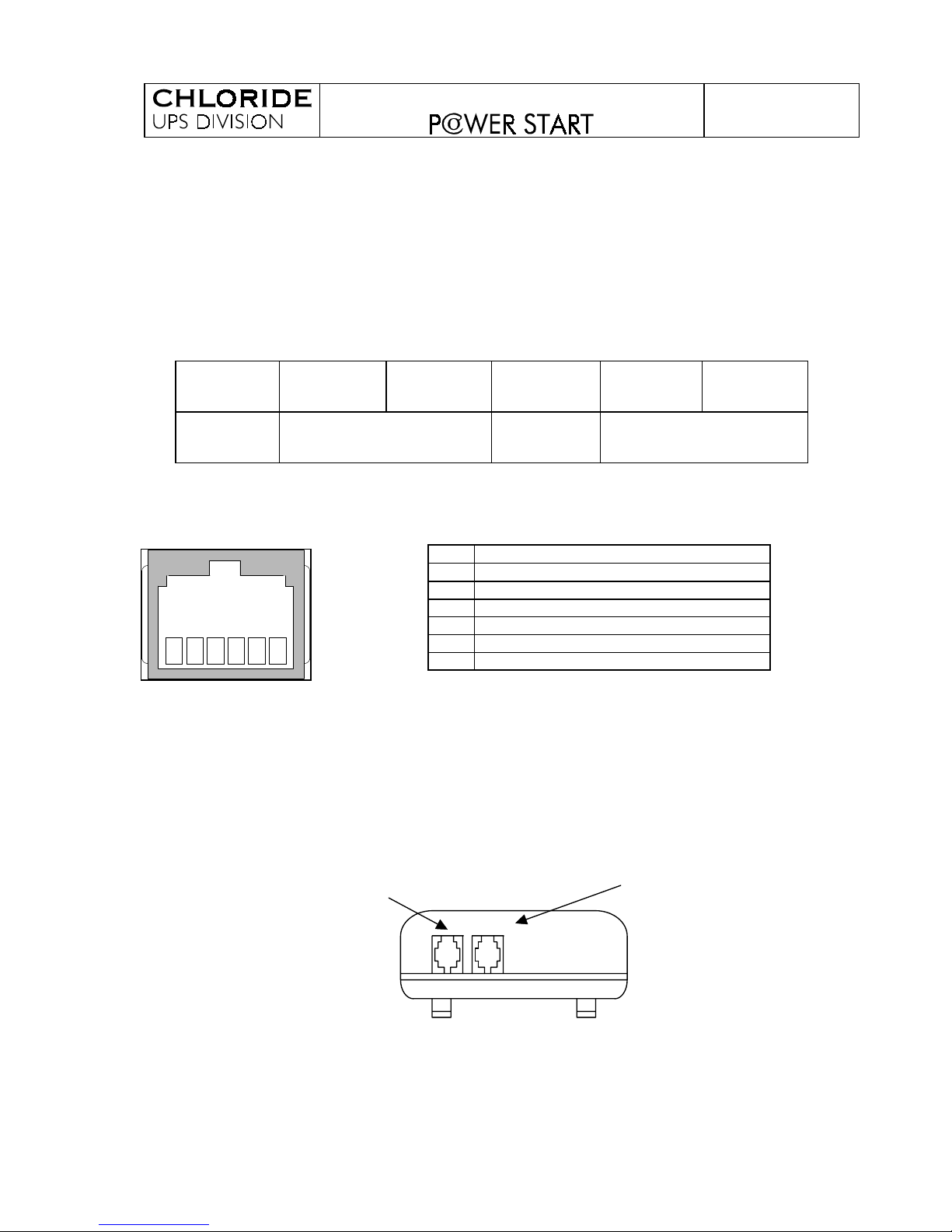
2.4 - Communication connector ( RJ11 6/6 )
Pin Description
1
+5 V @ 20mA
2 Battery Low
3 Mains Failure
4 Ground
5 RDX ( Receives date from a PC )
6 TDX ( Transmits data to a PC )
This connector is used to communicate with the user and maintenance Softw are.
“MUST BE USED WITH ONDYNE COMMUNICATION INTERFACE”.
All signals work with TTL levels.
2.5 - ONDYNE Communication Interface
SHUTDOWN
RS232
6 4
1
235
Page 3
TECHNICAL MANUAL
942088.001
942088.001 - 24/09/98
3
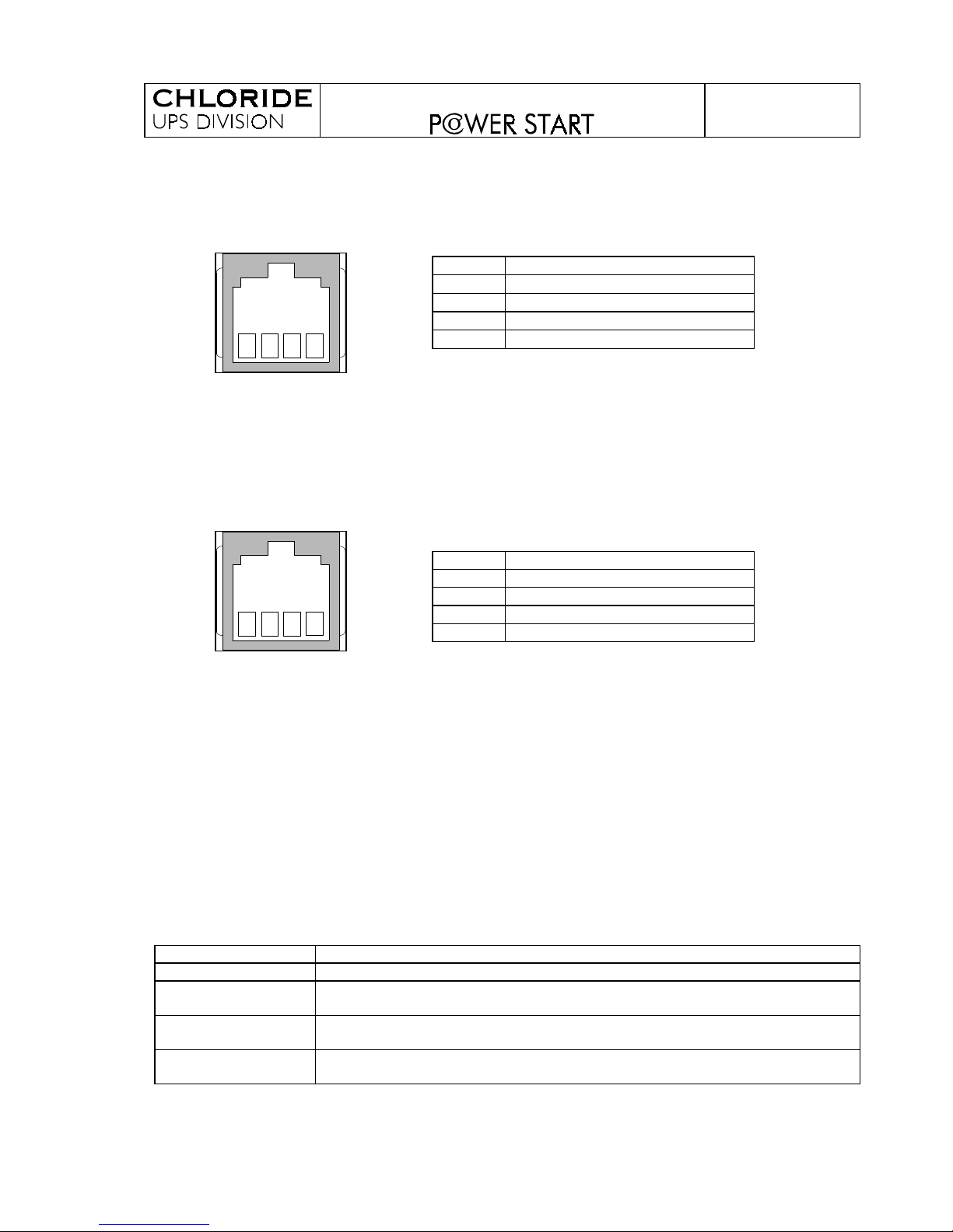
2.5.1 - RS232 connector (RJ11 type) w ith the following signals:
Pin Description
1
Reserved ( +5V @. 10mA )
2
TDX, ( Transmits date to the PC )
3
Ground
4
RDX, ( Receives data from the PC )
Pin 1 is reserved for special purposes. Sig nal s 2 and 4 ar e “R S232” levels. This connector is
used for the serial communication with the PC using the U ser and Technical Softw ar e.
2.5.2 - SHUTDOWN connector (RJ11 type) with the following sig nal s:
Pin Description
1
Battery Low
2
Mains Failure
3
Ground
4
-----------------
It is used for automatic operations such as files server shutdow n, etc.
The signals are “RS232” levels .
It is necessary to use special cables such as MODEL 42 to prov i de Vol t Free C ontacts (VFC ) .
The “Battery Low” and “Mains Fail ure” l og ic si g nal s are Softw ar e configur abl e.
2.6 - LEDs
The green LED indicates us than the unit is operating on mai ns and within its limits.
If the unit is operating on-battery , the red LED i s on.
When the LEDs are off the unit is switched off .
2.7 - Acoustic Signals.
ON BATTERY: One “bip” of 0,5 sec. every 15 sec. The UPS is on-battery and discharging them.
AUTOTEST MODE: Five “bips” every 5 sec. The unit carries out an internal autotest when it starts up.
PREWARNING
MODE:
One “bip” of 0,5 sec every sec. The UPS battery is low.
HISTORIC MODE: Two fast “bips” . An event has occurred and has been storage in the UPS memory.
(Mains failure, overload , etc.).
ALARM MODE: Four small “bips” and one long “bip” every second. An user’s alarm has been
activated ( overload ).
4
1
23
4
1
23
Page 4

TECHNICAL MANUAL
942088.001
942088.001 - 24/09/98
4
3.- BASIC OPERATION.
“POWER START” has no ON/OFF switch, when the mains voltage is present the unit
automatically starts up. The UPS can turn its output off by the “TIME PROGRAM M ER” or by
“AUTO-OFF”.
During the start up, the UPS does an “AUTOTEST”, if the battery, internal ci r cui ts and
the mains are correct, it will connect the relays supplying voltag e to the output.
The microprocessor continually checks the mains, when it fails, the inverter supplies
AC power to the load. The load normally operates until the battery is exhausted. The UPS
automatically transfers the load back to the mains power and recharges the batteries when
the mains voltage returns to normal.
The UPS provides automatic voltage regulator in two steeps, central and boost. It
corrects low input voltage without drawing power from the battery. Even with low input
voltage the unit can recharge the battery.
The commutation between steps is performed using relays. The unit will turn to
batteries for a few seconds, thus the commutation time will be lower.
The UPS operation is fully controlled by a microprocessor that is continuously
checking all the parameters and processes:
- Battery voltage.
- Output current (only on inverter).
- Mains input voltage, zero crossing points and phase.
- Output voltage.
- Vigilance of the internal voltages.
- Vigilance of the inverter.
- Relays (back - feed and voltage regulation)
- Charger of the battery
- RS232 Communication
Explanation about the types of switching off the UPS:
1.- AUTO-OFF : Automatic switch off. When the UPS is working on battery and the output
current is lower than the “MINIMUM THRESHOLD” the UPS will turn its output off after 30
seconds. The unit starts up again when the mains is present.
2.- Switch off by SOFTWARE. There are three possible commands :
•
IMMEDIATE switch off: the UPS will immediately cut its output off after receiving this
command. The UPS will remain in “STAND-BY” mode. The UPS can be only started up
using the “START UP” command.
•
PREWARNING switch off: the UPS will go on batteries for a period of time equal to the
“PREWARNING TIME”, and then the unit will stop. The UPS will remain in “STAND-BY”
mode. The UPS can be only started up using the “START UP” command.
•
TOTAL switch off : After receiving this order the UPS cuts its output vol tag e and i ts
internal power supply off. With this switch off mode the UPS losses the date the time and
cannot communicate with the computer. It will start up when the mains come back.
Page 5
TECHNICAL MANUAL
942088.001
942088.001 - 24/09/98
5
3.- TIMER switch off: The UPS switch off will be carried out at the time and the date recorded.
The UPS will remain in “STAND-BY” mode. The UPS will start up with the “TIMER” switch
or with “START UP” command if the mains is present.
4.- Stop due to protection: The UPS has one protective feature that could force it to stop (
Short circuit in the Output). The UPS will remain in “STAND-BY” mode.
5.- Exhausted Autonomy: If the UPS is on battery the UPS will stop when the time of
“AUTHORIZED AUTONOMY” has passed or the batter y voltage reaches 10V. The UPS
will remain in “STAND-BY” mode.
Notes:
In “STAND-BY” mode the UPS is consuming batter y for its internal electronic circuits. In
order to preserve the battery energy this power supply will be stopped when the
“MAXIMUM TIME IN STAND-BY ” has finished or the batter y voltage has reaches 11V.
The unit must be recharged after a long time in storag e.
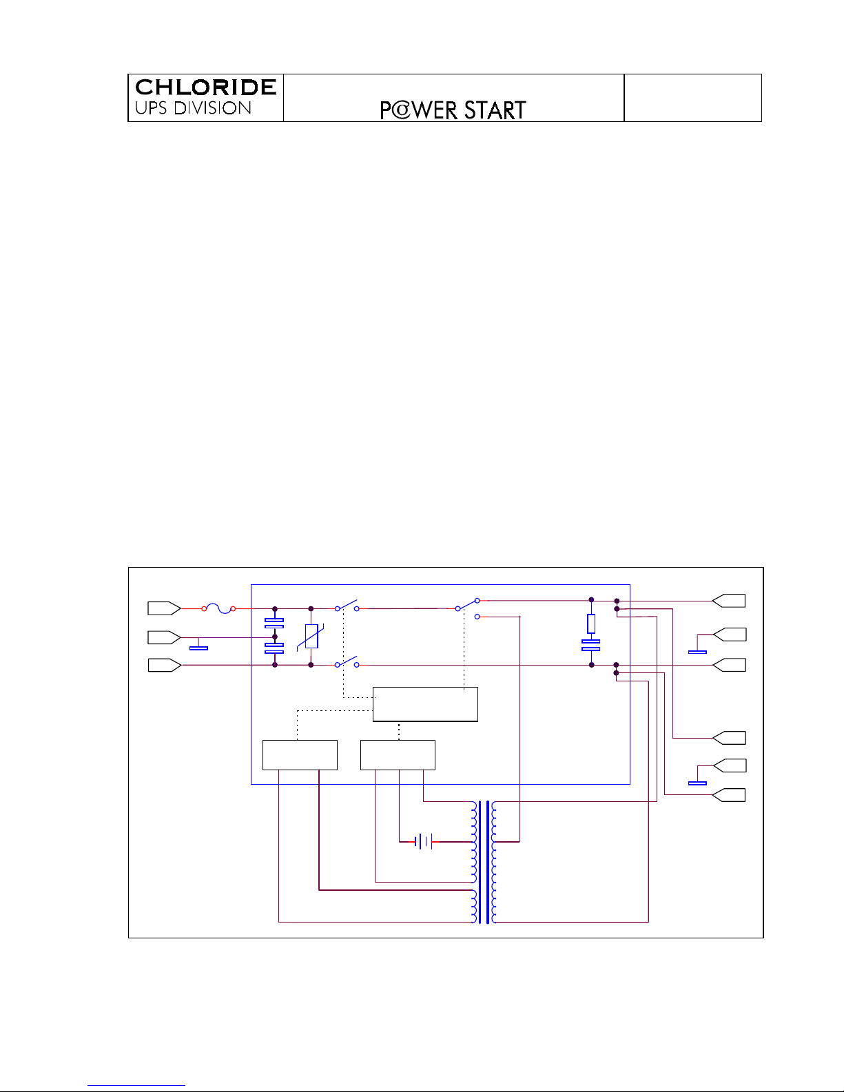
BLOCK DIAGRAM
A
B
S
C
D
N
KML
INPUT OUTPUT 1
OUTPUT 2
BOARD
H
ST1
INVERTER
BAT.
RL2
RL1
RL3
D
C
B
Nin
G
G
A
Lin
G
CPU
CHARGER
Page 6

TECHNICAL MANUAL
942088.001
942088.001 - 24/09/98
6
4.- MAINTENANCE PROCEDURE
1º If the UPS does not provide the expected back up time, recharge the battery for at
least 8 hours. If the autonomy is still low replace the battery. (Take care not to
damage the LEDs’ cover during the replacement).
Replace the battery with the same type as originally installed ( Sealed lead acid, maintenance free 12V
- 7Ah), supplied by the UPS manufacturer (Chloride Part. No.580085.000) with a polarised connector.
The battery contains toxic materials. Dispose of battery properly (must be recycled).
2º Look inside the unit and look for any damag e. ( Take care not to damag e the LED s’
cover when you are openi ng the uni t).
3º Check battery fuses. If the fuses are broken we can change them but not without
knowing the cause of this failure.
The battery fuses are on the PCB. They ar e automotive fuses of 30A and 32V
4º Connect the UPS to the mains for 1 or 2 seconds, this is onl y to wake-up its circuits .
5º Check the historic to find the possible fault. If the unit doesn’t communicate perhaps
there’s something wrong i n the communicati on ci rc uit or i n the micr opr ocessor or with
the voltage.
6º Use the soft to verify that the sy stem variables have the right values.
7º Apply the mains and w ait for the start up. If the unit doesn’t star t, check the
“AUTOTEST BYTE” and see why it hasn’t started. If every thi ng i s r i g ht, check the
“STATUS BYTE” to verify if the unit was stopped by Softw are or by “TIMER”.
8º When the UPS is operating, we must calibrate it w i th the automati c cali br ation
program.
9º Finally, di scharge the unit for a few minutes with the nominal charge and later plug the
unit to the mains for at least eight hours to totally charge the battery.
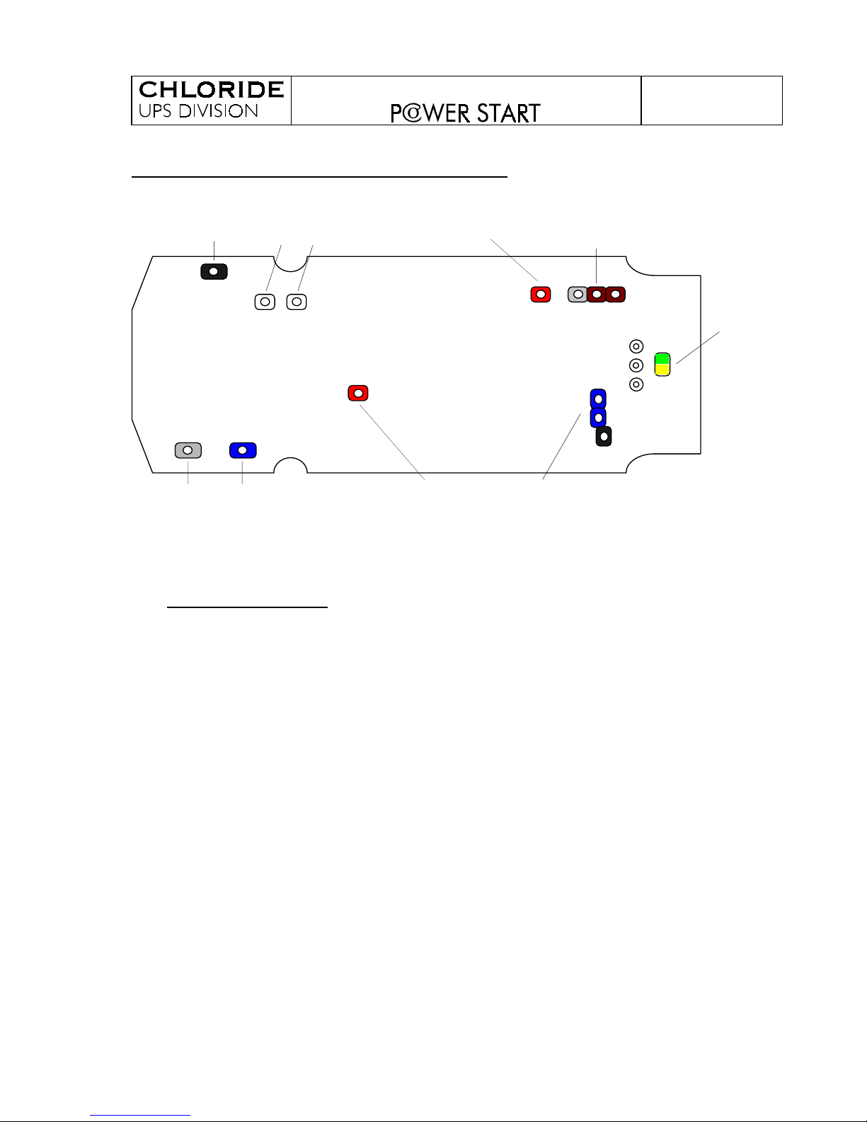
NOTE: In the next figur e you can see the correct position of the PCB wires.
Recommended for security, put the black w i re ( N eg . Batt.) in the l ast positi on.
And take care not to touch the heatsinks with this wir e.
REVISION NOTE : If any repair or modification, affecting the revision of the equipment, is
carried out, then this situation should be reflected on the identification sticker.
Page 7
TECHNICAL MANUAL
942088.001
942088.001 - 24/09/98
7
WIRES SOLDER TO THE POWER START BOARDS
WHITE WHITE
(L) (M)
GRAY 4
(I)
BLUE 4
(K)
BLACK 4
(NEG BAT)
BLUE BLACK BLACK
(N,C,D)
GRAY BROWN BROWN
(Lin)
GREEN
YELLOW
RED ST1
RED (+BAT)
5.- ELECTRONIC BOARD OPERATION
5.1 Measurements circuits.
5.1.1
Battery Voltage: R8 and R9 provide to the microprocessor PD2 pin (analogy input)
an image of the battery voltage.
5.1.2
Output Current: The UPS will only measure the output current when operating onbattery. It measures the MOSFET power transistors VDSon. This voltage is
amplified with IC4D and is applied to the PD4 pin.
5.1.3
Mains Measurement: In the microprocessor PD1 pin there is an image of the input
voltage, this is provided by TR1 transformer, a bridge rectifier (D21, D22, D23 and
D24) and a divider (R15, R43).
TR1 and previous diodes make an interruption to the micro ( IRQ ) when the mains
crosses zero. This signal is filtered through R30 and C17.
With the previous circuit and R13, the micro knows the mains voltage phase.
The diodes D13, D14 and D15 are used as pull-up protection.
5.1.4
Output Voltage: Through a bridge rectifier (D18, D19, T4 and T5) and a divider
(R29, R48) is performed the measurement of the output voltage in the input PD7.
Page 8
TECHNICAL MANUAL
942088.001
942088.001 - 24/09/98
8
5.2 Charger block and internal mains
The L and M terminals are connected to the transformer winding charger. This signal
is rectified with D4, D3, T4 and T5. IC5 regulates the charger voltage in function of the
voltage of the ADJ pin. With IC2B, the micro can stop the charger. The control of the
charger current is made with R19, R20, R21 and R22.
The battery or IC5 supply the voltage for the internal circuits. IC3 output supplies five
volts.
5.3 Start up circuits.
When there is mains voltage, the transformer TR1 voltage switches T3 on, T1 is also
switched on and IC3 supplies 5V.
When the mains is cut off or out of range, the microprocessor supplies voltage to PB0
during “STAND-BY”.
5.4 Reset Circuits.
This circuit makes a reset to the microprocessor when the 5V supply drops bellow the
security level. IC2A compares supply voltage, through R33 and R34, with a reference
of 0,6V fixed by D1 and R32.
5.5 Output Block.
The A, B, S and N, C, D are the UPS output terminals. When the unit works with
mains RL2 and RL3 (Back-Feed relays) are activated, when it’s on-battery RL2 and
RL3 aren’t activated.
RL1 controls the steps (Central and Boost). In normal operation the RL1 isn’t activated
and the unit is in the central step. When the input voltage is low the boost step is
activated (RL1).
5.6 Power Block.
It is a Push-Pull converter ( T7, T10 and T8, T9 ) and Null ( T4 and T5 ). With IC4A,
IC4B and IC4C the micro controls the power MOSFET.
5.7 Protection Circuit for VDSon
.
With this circuit the micro studies the MOSFET current when the unit is on-battery.
IC2C compares the VDSon with a reference voltage fixed by R12 and R46, so that if
the VDSon is higher than the reference voltage, IC2C sends an interruption to the
micro. IC2D initialises the protection in each branch.
Page 9
TECHNICAL MANUAL
942088.001
942088.001 - 24/09/98
9
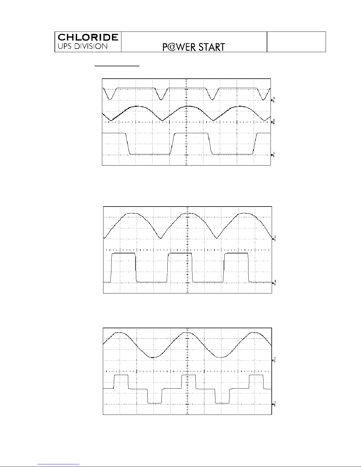
5.8 Boards Signals.
Mains voltage measurement ( 3.- Zero crossing IRQ )
( 2.- Mains voltage )
( 1.- Mains phase )
Output voltage measurement ( 2.- On mains )
( 1.- On inverter )
Output voltage waveform ( 2.- On mains )
( 1.- On inverter )
 Loading...