

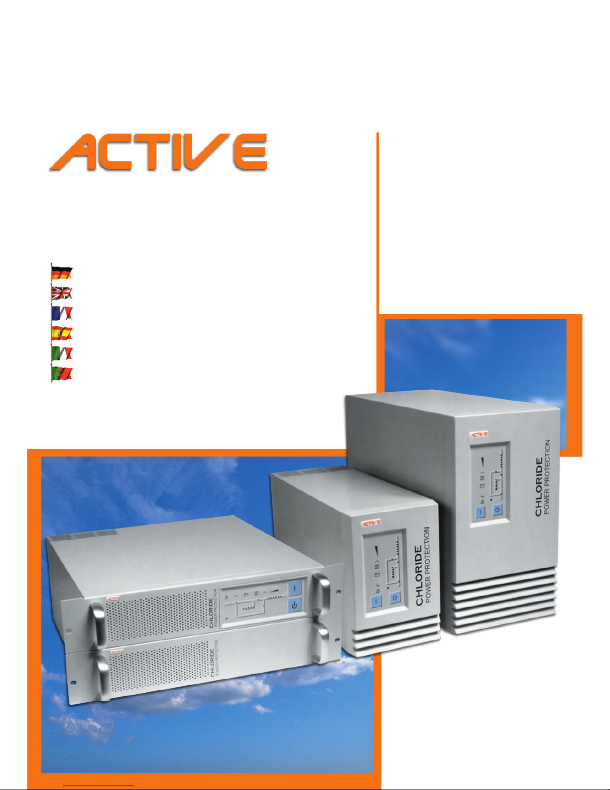
Chloride ACTIVE 700, ACTIVE 3000, ACTIVE 1000, ACTIVE 700-19, ACTIVE 1000-19 Operating Manual
...Page 1
&+/25,'(
219'42416'%6+10
Bedienungsanleitung
Operating Manual
Manuel utilisateur
Instrucciones de servicio
Istruzioni per l’uso
Manual de instruções
• Unterbrechungsfreie Stromversorgung
• Uninterruptible Power System
• Alimentation Sans Interruptio n
• Sistema de Alimentación Ininterrumpida
• Gruppo di continuità
• Sistema ininterrupto de alimentação
TOWER
DFWLYH
DFWLYH
DFWLYH
DFWLYH
RACK
DFWLYH
DFWLYH
DFWLYH
DFWLYH
Page 2

Page 3

D
F
E
I
G
B
P
• Unterbrechungsfreie
Stromversorgung
• Uninterruptible
Power System
• Alimentation Sans
Interruption
• Sistema de Alimentación
Ininterrumpida
• Gruppo di continuità
• Sistema ininterrupto
de alimentação
TOWER RACK
DFWLYH DFWLYH
DFWLYH DFWLYH
DFWLYH DFWLYH
DFWLYH DFWLYH
Bedienungsanleitung
Operating Manual
Manuel utilisateur
Instrucciones de servicio
Istruzioni per l’uso
Manual de instruções
&+/25,'(
219'42416'%6+10
Page 4

Alle Rechte vorbehalten, insbesondere
(auch auszugsweise) die der Übersetzung,
des Nachdrucks und der Wiedergabe durch
Kopieren oder ähnliche Verfahren.
Zuwiderhandlungen verpflichten zu
Schadenersatz.
Alle Rechte vorbehalten, insbesondere für
den Fall der Patenterteilung oder
GM-Eintragung.
Liefermöglichkeiten und technische Änderungen vorbehalten.
D
Copyright © CHLORIDE POWER PROTECTION
Tous droits réservés, y compris pour la traduction, la reproduction même partielle par
impression, photocopie ou autres méthodes
analogues.
Les infractions sont passibles de poursuites.
Tous droits réservés, y compris ceux issus de
l'attribution d'un brevet ou de l'enregistrement
d'un modèle ou d'un dessin d'utilité.
Livraison en fonction des disponibilités. Siemens se réserve le droit d'apporter des modifications sans préavis.
Reservados todos los derechos, incluso el derecho de la traducción completa o parcial, la
reimpresión, la reproducción por copias o por
otros métodos análogos.
Las infacciones darán derecho a una indemnización por daños sufridos.
Reservados todos los derechos especialmente en caso de la concesión de patentes o de
modelos de utilidad.
Entrega sometida a disponibilidad. Reservado
el derecho de establecer modificaciones técnicas.
F
E
All rights, including rights of translation, reproduction by printing, copying or similar methods, even of parts, are reserved.
Offenders will be liable for damages.
All rights, including rights created by patent
grant or registration of utility model or desig n,
are reserved.
Delivery subject to availability. Right of technical modification reserved
GB
Todos os direitos reservados, sobretudo os
de tradução (também parcial), de reprod ução
gráfica e de reprodução por meio de có pias e
processos semelhantes.
Não observância implica em cobrança de indenização.
Todos os direitos reservados, sobretudo em
caso de conferência de patente ou marca registrada.
Possibilidades de entrega e alterações técnicas estão reservadas.
P
Tutti i diritti riservati, inclusa la traduzione, ristampa e riproduzione anche parziale, a
mezzo di fotocopie o con metodi simili.
Le infrazioni comportano il risarcimento dei
danni.
Tutti i diritti riservati, inclusi i diritti derivanti
da eventuale concessione di brevetto e registrazione del modello di utilità.
Fornitura in base alle disponibilità . Con riserva del diritto di apportare modifiche tecniche.
I
Page 5

945040.066 V02OCT/01 GB - 1
CHLORIDE ACTIVE Table of contents
G
B
Table of contents
Chapter overview
Table of contents............................................................................ GB - 1
Chapter overview GB - 1
Tables and figures GB - 3
About these operating instructions .............................................. GB - 5
Device overview GB - 5
Notices regarding the EU Declaration of Conformity GB - 6
Symbols and pictograms GB - 6
Documentation structure GB - 6
Safety ............................................................................................... GB - 7
Intended use GB - 7
Safety Notices GB - 7
Introduction..................................................................................... GB - 9
Indicator and operating elements ............................................... GB - 12
Front side GB - 12
Rear side (upright devices) GB - 13
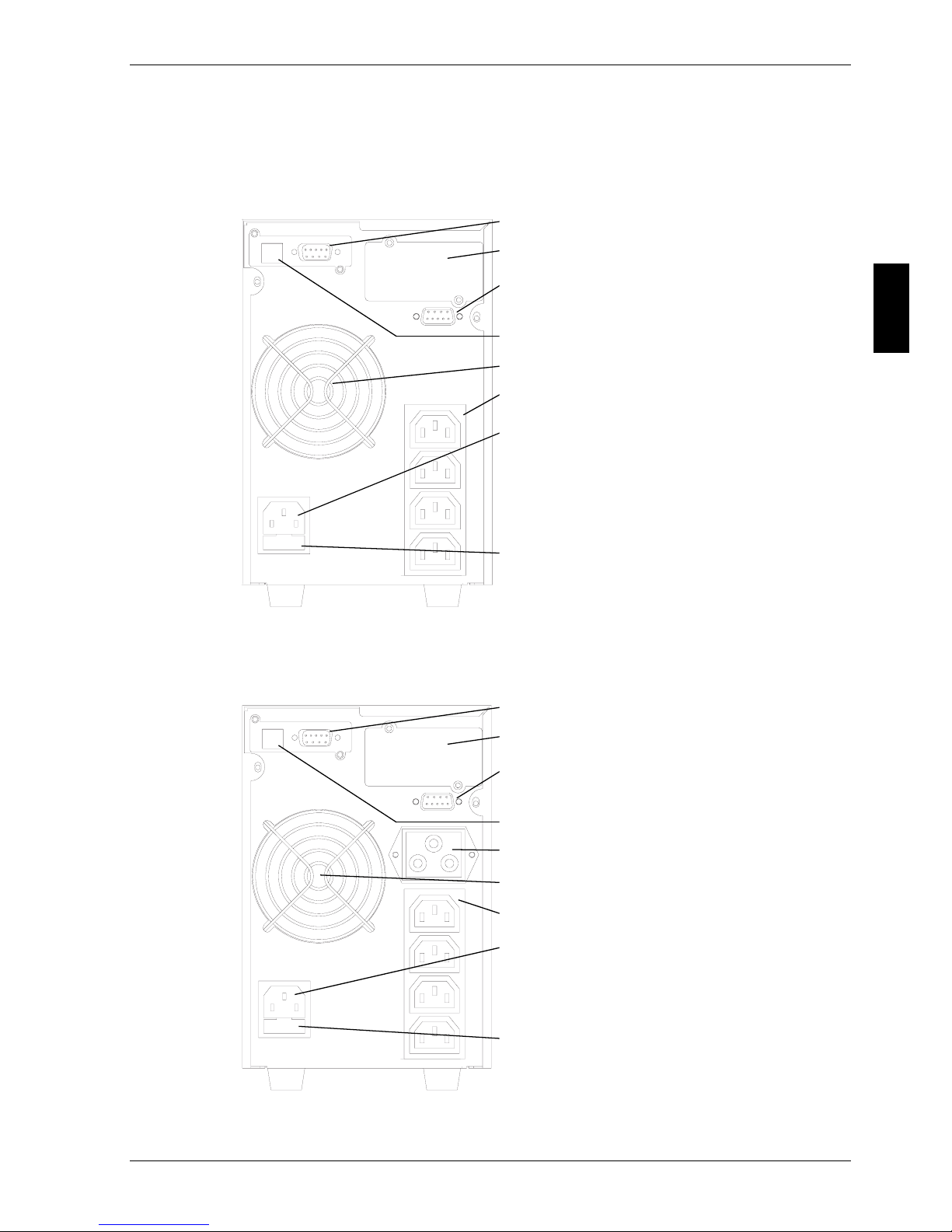
Models ACTIVE 700 and ACTIVE 1000 GB - 13
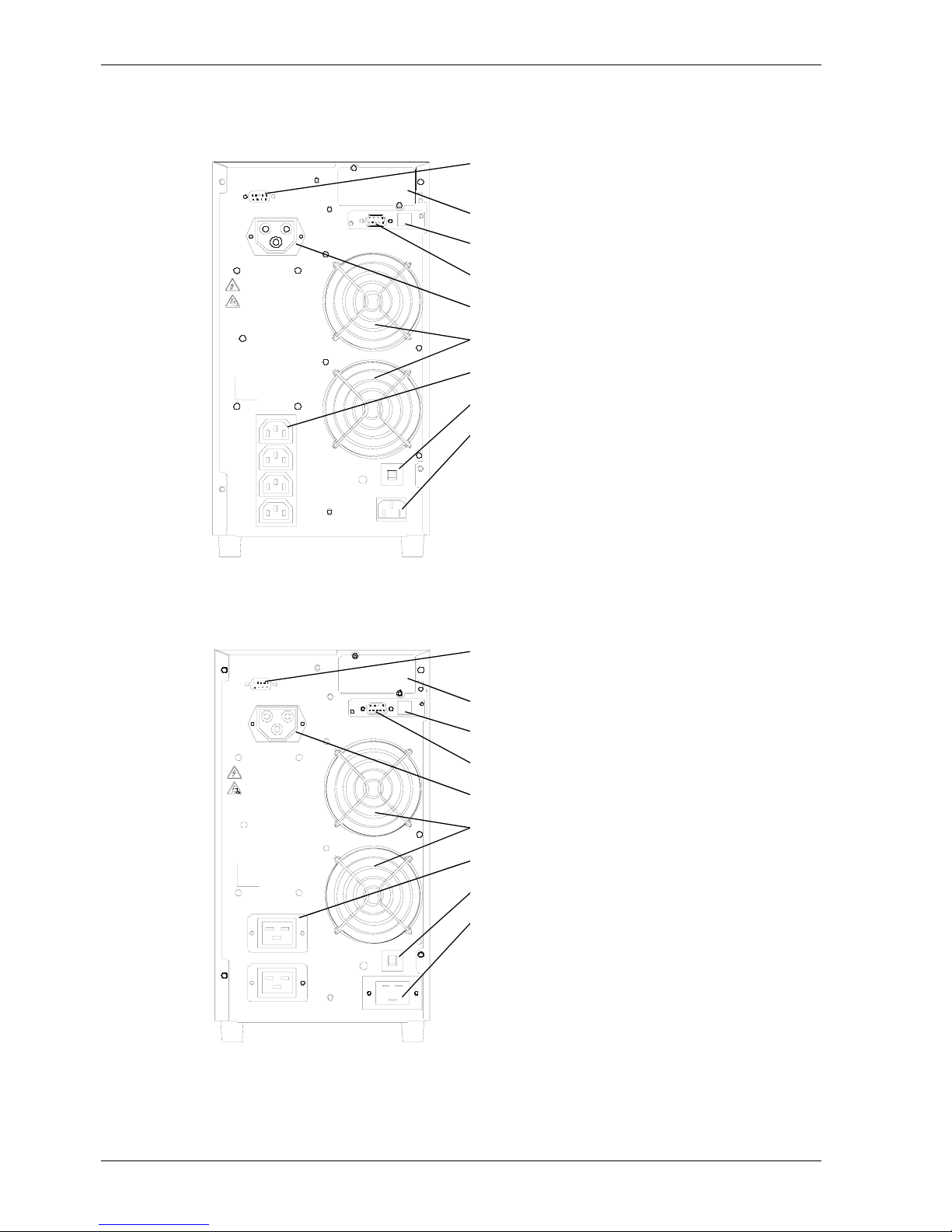
Models ACTIVE 2000 and ACTIVE 3000 GB - 14
Rear side (rack-mounting devices) GB - 15
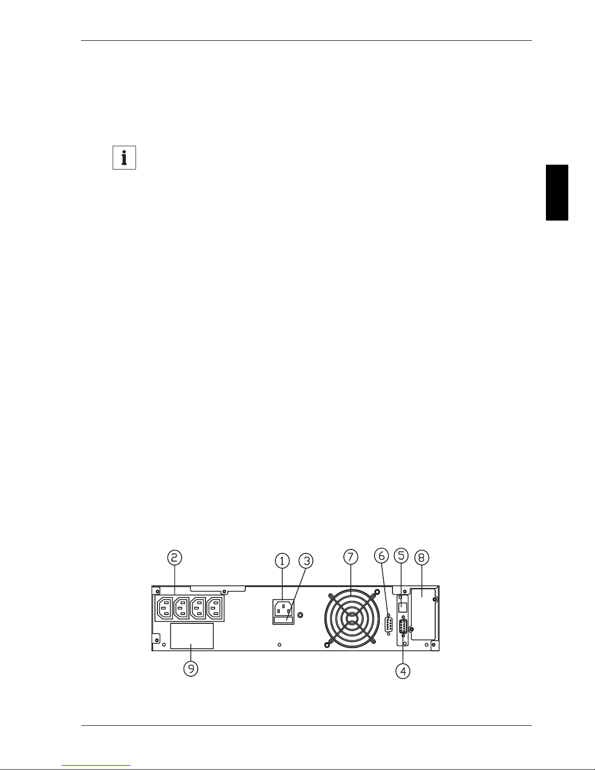
Models ACTIVE 700-19 and ACTIVE 1000-19 GB - 15
Models ACTIVE 2000-19 and ACTIVE 3000-19 GB - 17
Installation and commissioning.................................................. GB - 19
Installation notes for rack-mounting devices GB - 19
Selecting the installation site: GB - 19
Mechanical fixing: GB - 20
Installing the UPS devices GB - 21
Commissioning the UPS devices GB - 22
Commissioning of an external battery extension GB - 23
Special information for ACTIVE 2000-19 and ACTIVE 3000-19 GB - 24
Adjusting the number of external battery extensions GB - 25
Operational behaviour.................................................................. GB - 27
Checking the operational readiness GB - 27
Automatic test GB - 27
Lamp test GB - 27
Battery test GB - 28
Operating modes GB - 29
Normal operation (mains supply present) GB - 29
Battery operation (mains failure) GB - 30
Bypass operation (overload > 130 %) GB - 30
Page 6

GB - 2 V02OCT/01 945040.066
Table of contents CHLORIDE ACTIVE
Interface description ..................................................................... GB - 31
COM 3 standard interface GB - 31
USB interface GB - 32
Optional COM interface GB - 32
EXT. OUTLETS CONTROL interface GB - 34
Maintenance................................................................................... GB - 35
Storage GB - 35
Cleaning GB - 36
Troubleshooting ............................................................................ GB - 37
Technical data.......................................... ... ......................... ... ....... GB - 39
Technical data for the models ACTIVE 700 to ACTIVE 3000 GB - 39
Technical data for the models ACTIVE 700-19 to ACTIVE 3000-19 GB - 42
Usable Battery lifetime GB - 45
Typical battery backup times GB - 46
Page 7

945040.066 V02OCT/01 GB - 3
CHLORIDE ACTIVE Tables and figures
G
B
Tables and figures
Overview of UPS devices .................................................................. GB - 5
Overview of battery extensions.......................................................... GB - 5
Backup time..................................................................................... GB - 10
Battery capacity ............................................................................... GB - 10
Symbols on the front side of the UPS.............................................. GB - 11
UPS control panel................................... ... ...................................... GB - 12
Rear side ACTIVE 700..................................................................... GB - 13
Rear side ACTIVE 1000........................................... ... ..................... GB - 13
Rear side ACTIVE 2000........................................... ... ..................... GB - 14
Rear side ACTIVE 3000........................................... ... ..................... GB - 14
Rear side ACTIVE 700-19 ............................................................... GB - 15
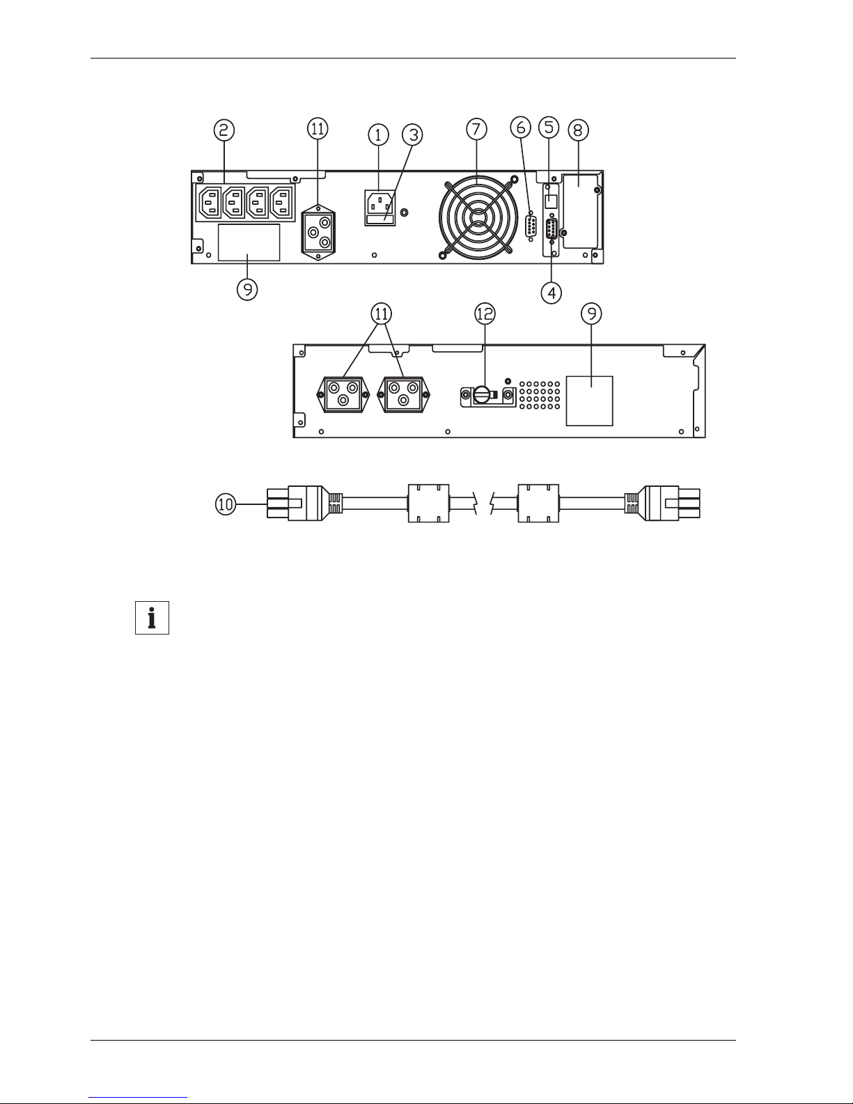
Rear side, ACTIVE 1000-19 and battery extension......................... GB - 16
Rear side ACTIVE 2000-19 and battery extension.......................... GB - 17
Rear side ACTIVE 3000-19 and battery extension.......................... GB - 18
Installing the slide rails on the UPS or battery extension................. GB - 20
Battery extensions (maximum expansion)....................................... GB - 23
Connection of battery extensions..................................................... GB - 24
Number of external battery extensions .......................................... .. GB - 26
UPS control panel in normal operation............................................ GB - 29
UPS control panel in battery operation............................................ GB - 30
UPS control panel in bypass operation............................................ GB - 30
COM 3 interface............................................................................... GB - 31
COM 1 interface............................................................................... GB - 33
Rectification of errors.................................... ... .. .............................. GB - 37
Electrical data (ACTIVE 700 to ACTIVE 3000)................................ GB - 39
General data (ACTIVE 700 to ACTIVE 3000).................................. GB - 40
Mechanical data (ACTIVE 700 to ACTIVE 3000) ............................ GB - 40
Connections (ACTIVE 700 to ACTIVE 3000)................................... GB - 41
Other data (ACTIVE 700 to ACTIVE 3000)...................................... GB - 41
Electrical data (ACTIVE 700-19 to ACTIVE 3000-19)...................... GB - 42
General data (ACTIVE 700-19 to ACTIVE 3000-19) ....................... GB - 43
Mechanical data (ACTIVE 700-19 to ACTIVE 3000-19).................. GB - 43
Connections (ACTIVE 700-19 to ACTIVE 3000-19)........................ GB - 44
Other data (ACTIVE 700-19 to ACTIVE 3000-19)........................... GB - 44
Usable battery lifetime ..................................................................... GB - 45
Backup times ACTIVE 700(-19) and ACTIVE 1000(-19)................. GB - 46
Backup times ACTIVE 2000(-19)..................................................... GB - 46
Backup times ACTIVE 3000(-19)..................................................... GB - 47
Page 8
GB - 4 V02OCT/01 945040.066
CHLORIDE ACTIVE Tables and figures
Notice
For reasons of clarity, these operating instructions do no t contain
complete and detailed information about product types and do not
take into account all possible installation, operation and maintenance
cases.
Should you require additional informa tion, you can request the necessary information from your local CHLORIDE office (see section
“CHLORIDE ADDRESSES” at the end of this manual).
The contents of these operating instructions shall not become part of
or modify any prior agreement, commitment or relationship. The
sales contract contains the entire obligations of CHLORIDE. The
warranty contained in the contract between the parties is the sole
warranty of . Any statements contained herein do not create any new
warranties or modify the existing warranty.
Warning
Carefully read these instructions completely before installation in order to get accustomed with the correct handling of the CHLORIDE
ACTIVE UPS. Otherwise, especially during installation and operation, dangerous situations could arise.
Page 9

CHLORIDE ACTIVE About these operating instructions
945040.066 V02OCT/01 GB - 5
G
B
About these operating instructions
Device overview
The CHLORIDE ACTIVE UPS devices are delivered with various nomi nal
powers and in various housings. The following table provides an overview
of all device variants:
The following battery extensions are available:
The above listed rack-mounting devices (racks) with a mounting height of
2 HU are designed fo r horizontal installation in industri al standard 19-inch
cubicles.
Housing Designation Order No. Nominal power
Tower
(upright device)
ACTIVE 700 570219.200 700 VA
ACTIVE 1000 570220.200 1000 VA
ACTIVE 2000 570221.200 2000 VA
ACTIVE 3000 570222.200 3000 VA
Rack
(rack-mounting
device)
ACTIVE 700-19 570223.200 700 VA
ACTIVE 1000-19 570224.200 1000 VA
ACTIVE 2000-19 570225.200 2000 VA
ACTIVE 3000-19 570226.200 3000 VA
Table 1: Overview of UPS devices
Housing Designation Order No. for UPS device
Tower
(upright device)
BPACTIVE1000 570227.001 ACTIVE 1000
BPACTIVE3000 570227.101
ACTIVE 2000
ACTIVE 3000
Rack
(rack-mounting
device)
BPACTIVE1000-19 570228.001 ACTIVE 1000-19
BPACTIVE3000-19 570228.101
ACTIVE 2000-19
ACTIVE 3000-19
Table 2: Overview of battery extensions
Page 10

About these operating instructions CHLORIDE ACTIVE
GB - 6 V02OCT/01 945040.066
Notices regarding the EU Declaration of Conformity
The UPS devices CHLORIDE ACTIVE are in conformity with the following
European directives:
73/23/EWG Directive of the council for adaptation of the legal regulations of the member
states regarding electrical equipment for use with in specific voltage limits,
modified by directive 93/68/EWG.
89/336/EWG Directive of the council for adaptation of the legal regulations of the member
states regarding electromagnetic compatibility, modified by directive
91/263/EWG, 92/31/EWG and 93/68/EWG.
Conformity is established through compliance with the following standards:
• EN 50091-1-1 : 1996
• EN 50091-2 : 1995
Additional information regarding adherence to these directives is included in
the appendices NSR and EMC of the EU Declaration of Conformity.
If needed, the EU Declaration of Conformity can be requested from
CHLORIDE.
Symbols and pictograms
The following symbols and pictograms are used in this handbook:
Danger
Indicates notices which, if not observed, endanger your life, your
health, the reliability of your device or the security of your data.
Notice
Indicates additional information and tips.
Indicates a step that you must carry out.
Documentation structure
These instructions can be supplemented with additio nal sheets, which e.g.
describe specific extensions or options.
Page 11

CHLORIDE ACTIVE Safety
945040.066 V02OCT/01 GB - 7
G
B
Safety
Intended use
UPS devices serve as an uninterruptible power supply for connected loads.
They are in compliance with all relevant safety regulations concerning information technology equipment, including electronic office machines for u se
in an office environment.
In certain configurations, battery packs are part of the UPS devices. These
battery packs may only be connected electrically with the corresponding
base device.
Safety Notices
Danger
Carefully read the following safety notices! Failure to observe the notices endangers your life, your health, the reliability of your device or
the security your data.
• Use only suitable packaging to transport the device (protect agai nst
shock and impact).
• If the device is brought in from a cold environment, moisture condensation can occur. Before commissioning the device, it must be completely dry. For this reason, an acclimation time of at least two hours
is required.
• When selecting a location for the device and during commissioning,
observe the notices concerning environmental conditions given in
chapter “Technical data” on page GB - 39.
• Rack-mounting devices as well as the corresponding battery extensions must only be mounted in horizontal position (see chapter “Installation notes for rack-mounting devices” on page GB - 19).
• This device is equipped with a safe ty-inspected mains line and must
only be connected to a grounded earthing-contact socket.
•The button does not separate
the device from mains. To completely separate from mains, the UPS must be switched to bypass and
the mains plug pulled (see chapter “Indicator and operating elements”
on page GB - 12).
• Make certai n that the socket on the device or the earthing-contact
socket of the house installation is freely accessible.
Page 12

Safety CHLORIDE ACTIVE
GB - 8 V02OCT/01 945040.066
• Upon disconne ction from mains, the built-in battery continues to supply the loads.
• Lay the lines in such a way that no one can step on or trip over them
and so that the lines are not pinched. When connecting the device,
observe the notices in chapter “Installation and commissioning” on
page GB - 19.
• During thunderstorms, data transfer cables must not be conn ected or
disconnected.
• Ensure that no objects (e.g. jewellery chains, paper clips etc.) are left
inside of the device.
• In the event of an emergency (e.g. damaged housing, operating elements or mains lines, penetration of fluids or foreign bodies), switch off
the device, pull the mains plug and contact the responsible customer
service representative.
• Repair work may only be carried out by authorised personnel. Unauthorised opening and improper repairs can expose the user to serious
danger.
• Do not connect any devices which overload the UPS (e.g. laser printer
or vacuum cleaner) or which draw DC current from the UPS (e.g. halfwave rectifiers found in hair dryers).
• When cleaning, observe the notices in chapter “Maintenance” on page
GB - 35.
• The sum of the leakage currents (current in the earth conductor) from
the UPS and connected loads must not exceed the value of 3.5 mA for
the models ACTIVE 700(-19), ACTIVE 1000(-19), ACTIVE 2000(-19)
and ACTIVE 3000(-19).
Page 13

CHLORIDE ACTIVE Introduction
945040.066 V02OCT/01 GB - 9
G
B
Introduction
These operating instructions contain all the information needed to install and
operate the UPS.
The uninterruptible power supply (UPS) is connected between mains and
the electrical load. It protects the load from mains interruptions, especially
power failures.
This UPS operates according to the on-lin e principle. This means that the
connected loads are supplied via the inverter o f the UPS. This pr otects the
load from mains supply disturbances and provides a secure mains supply
for electrical loads (PCs, network servers, multi-console systems).
In case of a mains failure, the built-in, maintenance-free batteries provide
uninterrupted power to the loads. In actual use, mains failures are, depending on the quality of the mains supply, relatively short in duration. Thus, the
power supplied by the UPS is adequate to allow work to continue on your
computer system until mains voltage has been restored. In the event of an
extended mains failure, you should nevertheless store your data and discontinue your work.
You will be alerted by means of acoustical (buzzer) and optical (LED) alarms
contained in the UPS that a mains failure has occurred or is occurring. Listed
below are procedures which are intended to assist you in determining how
critical it is that work be discontinued in the event of an extended mains failure.
Which procedure you select depends primarily on the length of time required
to safely end your application and shutdown your operating system.
• In the extreme case, it is possible to work on a UPS-protected PC un til
the battery has reached its minimum power level. In the event of a
mains failure, an acoustical signal is output by the UPS every 4 seconds; if the minimum power level of the batteries is nearly reached,
this signal is output every second. This procedure is, however, seldom
required. While battery recharging begins immediately following restoration of the mains supply, the procedure may require several hours to
complete.
Page 14
Introduction CHLORIDE ACTIVE
GB - 10 V02OCT/01 945040.066
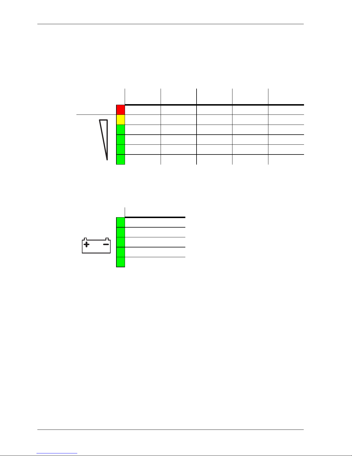
• The situation can be more accurately assessed using the load indicator on the UPS. If the load condition remains constant, it is possible to
use this indicator to deduce the remaining backup time. The following
figure illustrates the approximate values of the backup time for a fully
charged battery at the start of the mains failure.
• The current battery capacity can be read on the LED strip with the battery symbol (see table below).
• The most reliable method is, however, the use of the CHLORIDE UPS
software. This can be used to continuously display the estimated
remaining capacity of the battery prior to and during a mains failure. In
addition, you can automate shutdown processes. Depending on the
user program, operating system and computer hardware, you can
ensure that, during a mains failure, user programs are automatically
closed, users logged into the server are logged off, data are saved and
the operating system is shutdown. For further information, you are
referred at this point to the documentation for the CHLORIDE communication software.
After mains voltage is restored, the UPS automatically starts. The connected
computer systems start their operating systems. Depending on what UPS
software is installed, it is possible to restore the state which existed prior to
the mains failure.
Load in %
ACTIVE
700(-19)
ACTIVE
1000(-19)
ACTIVE
2000(-19)
ACTIVE
3000(-19)
Overload
> 105
Load
95-105 6 min 7 min 10 min 6 min
75-95 7 min 8 min 13 min 7 min
55-75 10 min 12 min 19 min 11 min
35-55 16 min 20 min 31 min 18 min
1-35 33 min 36 min 60 min 38 min
Table 3: Backup time
Battery capacity in %
1-35
35-55
55-75
75-95
95-100
Table 4: Battery capacity
Page 15

CHLORIDE ACTIVE Introduction
945040.066 V02OCT/01 GB - 11
G
B
In the event of an overload or an internal failure, the load is supplied without
interruption directly by the mains supply via the automatic bypass. As soon
as normal operating conditions are restored, the system automatically
switches back to inverter operation.
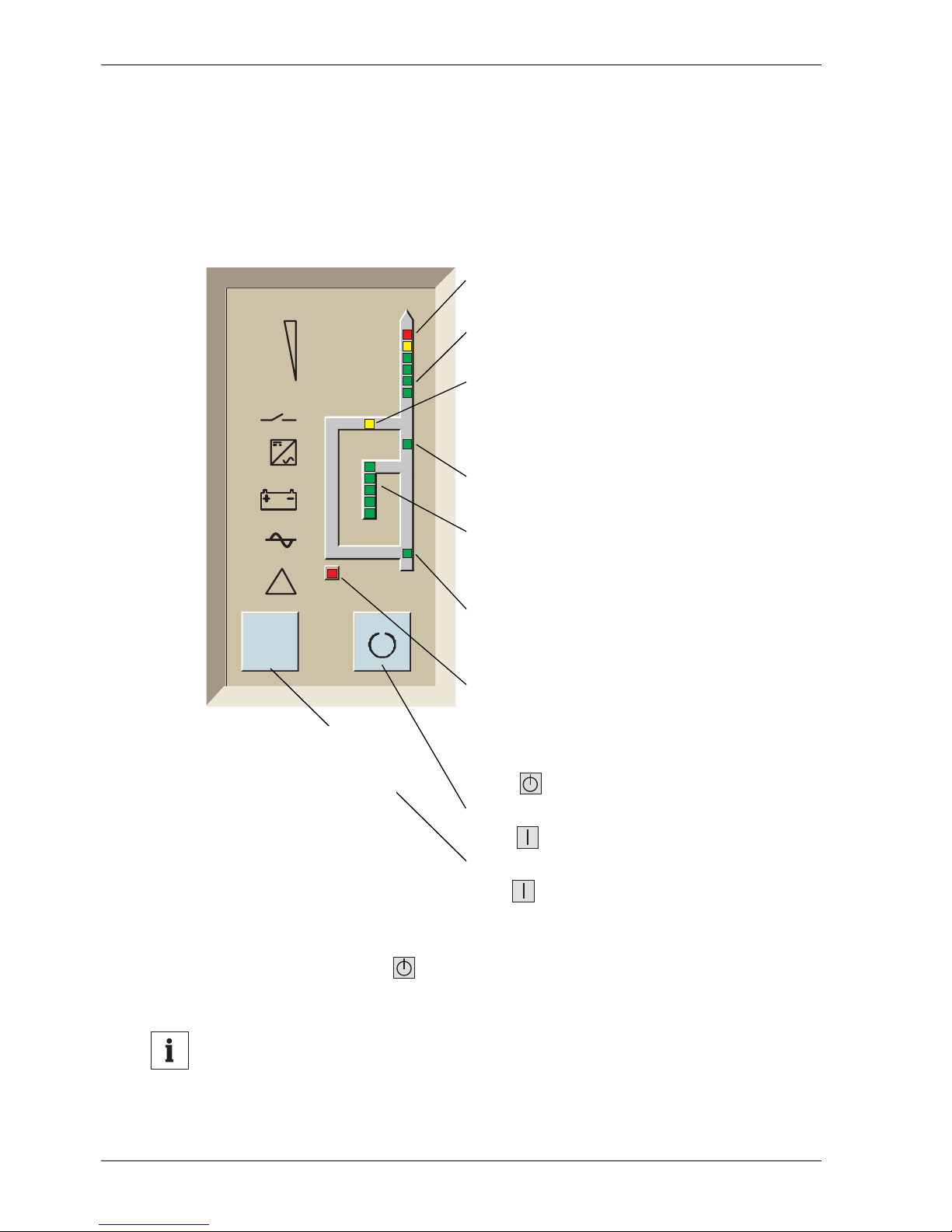
Below, the symbols located on the front side of the UPS are shown and
described:
Fig. 1: Symbols on the front side of the UPS
!
LOAD BYPASS INVERTER BATTERY MAINS ALARM
Page 16
Indicator and operating elements CHLORIDE ACTIVE
GB - 12 V02OCT/01 945040.066
Indicator and operating elements
Front side
The OVERLOAD indicator illuminates if
the UPS is overloaded.
The LOAD LED strip displays the load status of the UPS.
The BYPASS indicator illuminates when
the UPS delivers voltage supplied from
the mains supply via the bypass.
The INVERTER indicator illuminates
when the inverter is activated.
The BATTERY LED strip indicates the
charging state of the battery (normal operation).
The MAINS indicator illumina tes when
normal mains voltage is present at the
UPS input.
The ALARM indicator illuminates when
the UPS is in a faulty state. An acoustical
warning signal is output at the same time;
this signal is reset when the UPS is
switched off.
The button switches the inverter off
and the bypass on.
The button switches on the inverter.
The inverter is activated upon activation of
the button. Following a delay time of
approx. 5 seconds, the BYPASS indicator extinguishes and the INVERTER
indicator illuminates.
Upon activation of the button, the inverte r is blocked and i s switched to
bypass. The UPS output carries voltage.
Notice
To trigger an action, the buttons must be pressed for at least 1 second! (Acceptance of the input is confirmed acoustically)
I
I
!
Fig. 2: UPS control panel
Note: Fig. 2 corresponds
to the upright devices; the
display and operating elements for rack-mounting
devices are identical.
Page 17
CHLORIDE ACTIVE Indicator and operating elements
945040.066 V02OCT/01 GB - 13
G
B
Rear side (upright devices)
Models ACTIVE 700 and ACTIVE 1000
COM 3 interface
COM interface (optional)
EXT. OUTLETS CONTROL
interface
USB interface
Fan
Output sockets (AC OUTPUT)
Mains connection (AC INPUT)
Input fuse
The fuse must only be changed when the
device is switched off and the mains connection cable disconnected.
COM 3 interface
COM interface (optional)
EXT. OUTLETS CONTROL
interface
USB interface
Connection for battery extension
Fan
Output sockets (AC OUTPUT)
Mains connection (AC INPUT)
Input fuse
The fuse must only be changed when the
device is switched off and the mains connection cable disconnected.
Fig. 3: Rear side ACTIVE 700
Fig. 4: Rear side ACTIVE 1000
Page 18
Indicator and operating elements CHLORIDE ACTIVE
GB - 14 V02OCT/01 945040.066
Models ACTIVE 2000 and ACTIVE 3000
EXT. OUTLETS CONTROL
interface
COM interface (optional)
USB interface
COM 3 interface
Connection for battery extension
Fan
Output sockets (AC OUTPUT)
Input circuit breaker
Mains connection (AC INPUT)
EXT. OUTLETS CONTROL
interface
COM interface (optional)
USB interface
COM 3 interface
Connection for battery extension
Fan
Output sockets (AC OUTPUT)
Input circuit breaker
Mains connection (AC INPUT)
'
'
'
Fig. 5: Rear side ACTIVE 2000
Fig. 6: Rear side ACTIVE 3000
Page 19
CHLORIDE ACTIVE Indicator and operating elements
945040.066 V02OCT/01 GB - 15
G
B
Rear side (rack-mounting devices)
The following figures show the UPS rack-mou nting devices with the corresponding battery extensions.
Notice
No battery extensions can be connected to the ACTIVE 700-19
device.
Models ACTIVE 700-19 and ACTIVE 1000-19
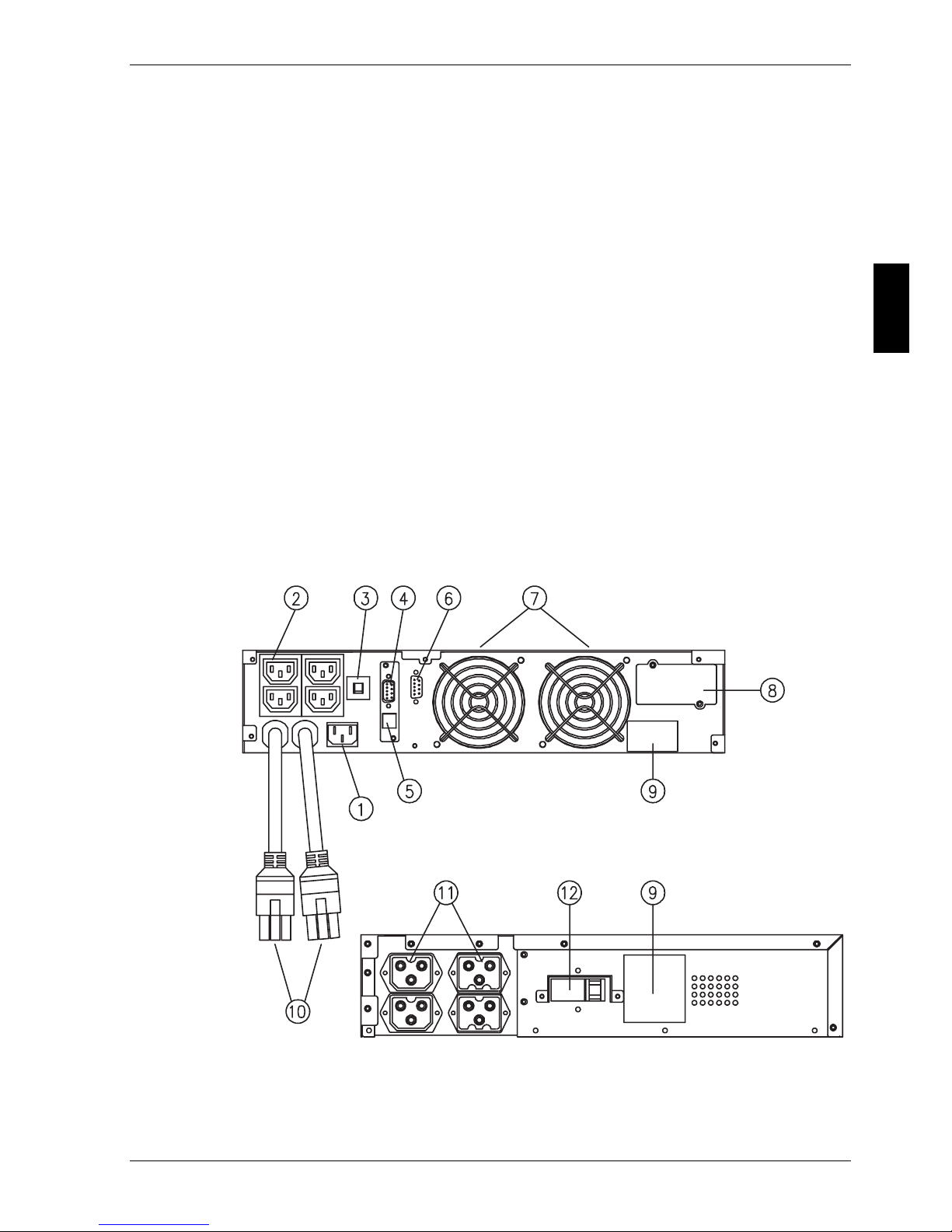
The following legend applies to figures Fig. 7 and Fig. 8:
(1) Mains connection (AC INPUT)
(2) Output sockets (AC OUTPUT)
(3) Input fuse
The fuse must only be changed when the device is switched off and
the mains connection cable disconnected.
(4) Interface COM 3
(5) Interface USB
(6) Interface EXT. OUTLETS CONTROL
(7) Fan
(8) COM interface (optional)
(9) Nameplate
(10) Battery-extension cable (not with ACTIVE 700-19)
(11) Connection for battery extension (not with ACTIVE 700-19)
(12) Battery switch (not with ACTIVE 700-19)
Fig. 7: Rear side ACTIVE 700-19
ACTIVE 700-19
Page 20
Indicator and operating elements CHLORIDE ACTIVE
GB - 16 V02OCT/01 945040.066
Fig. 8: Rear side, ACTIVE 1000-19 and battery extension
Notice
To connect the BPACTIVE1000-19 battery extension to the UPS
ACTIVE 1000-19, use the separate cable (10) provided in the
delivery contents.
ACTIVE 1000-19
BPACTIVE1000-19
Page 21
CHLORIDE ACTIVE Indicator and operating elements
945040.066 V02OCT/01 GB - 17
G
B
Models ACTIVE 2000-19 and ACTIVE 3000-19
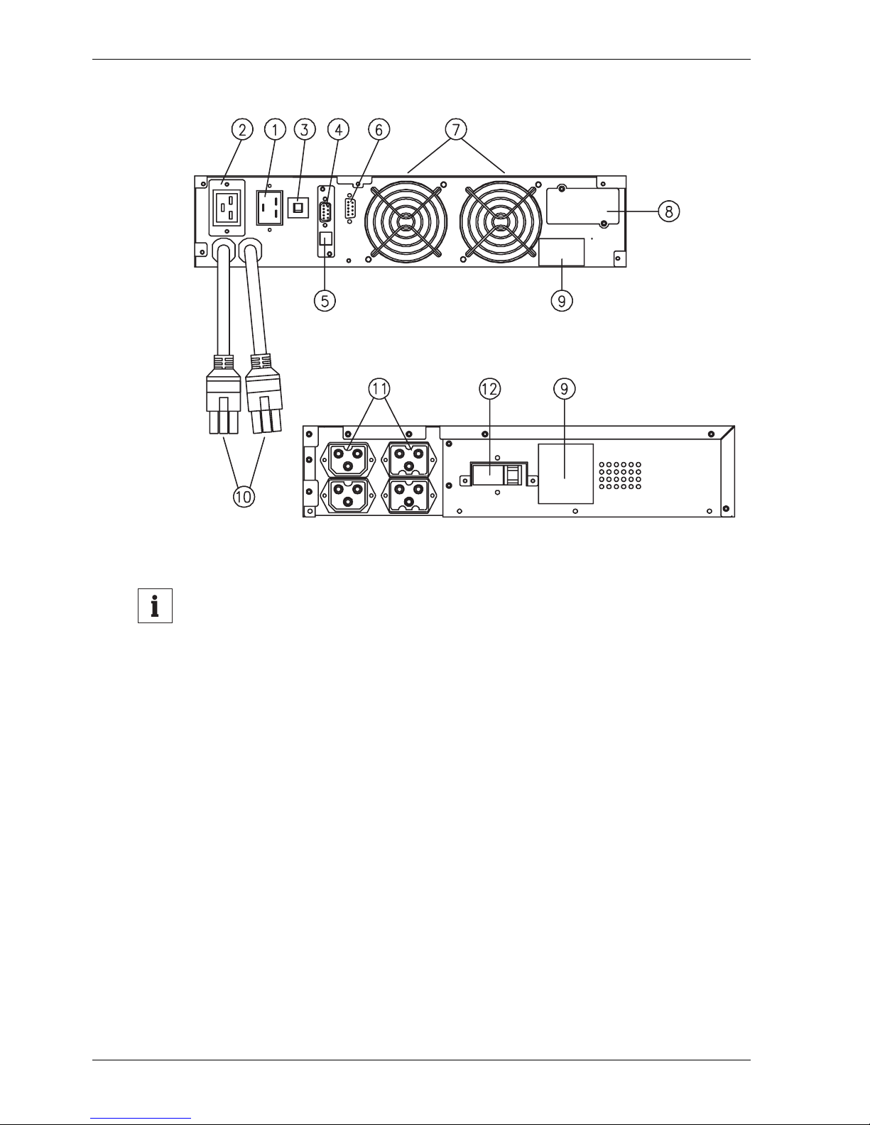
The following legend applies to figures Fig. 9 and Fig. 10:
(1) Mains connection (AC INPUT)
(2) Output sockets (AC OUTPUT)
(3) Input circuit breaker
(4) Interface COM 3
(5) Interface USB
(6) Interface EXT. OUTLETS CONTROL
(7) Fan
(8) COM interface (optional)
(9) Nameplate
(10) Battery extension cable (permanently mounted)
(11) Connection for battery extension
(12) Battery switch
Fig. 9: Rear side ACTIVE 2000-19 and battery extension
ACTIVE 2000-19
BPACTIVE3000-19
Page 22
Indicator and operating elements CHLORIDE ACTIVE
GB - 18 V02OCT/01 945040.066
Fig. 10: Rear side ACTIVE 3000-19 and battery extension
Notice
Included in the delivery contents for each BPACTIVE3000-19 battery
extension are two battery extension cables. The first extension is
connected to battery cable (10) of the UPS, each additional extension is connected via the two aforementioned cables. Protection
against polarity reversal at the battery extensions is ensured through
the coding of the plug (10) on the UPS device and the connection
socket (11).
ACTIVE 3000-19
BPACTIVE3000-19
Page 23

CHLORIDE ACTIVE Installation and commissioning
945040.066 V02OCT/01 GB - 19
G
B
Installation and commissioning
Inspect the packaging and the device for damages.
Should you find damages, please contact the delivery firm immediately.
Scope of delivery
• This manual
• UPS device
• Connection cable with IEC 320 plug for the UPS input
• Connection distribu tor with IEC 320 connection for the UPS output
• Communication softwa re (CD)
• RS 232 interface cable
Installation notes for rack-mounting devices
Selecting the installation site:
All rack-mounting devices (ACTIVE …-19) are intended for horizontal installation in 19-inch cubicles.
Notice
When installing the UPS, bear in mind the large weight of the individual components.
For weight purposes, mount the devices as low as possible in the cubicle.
When mounting UPS systems consisting of multiple components, mount the battery
extensions either directly below or directly above the UPS rack device.
Page 24
Installation and commissioning CHLORIDE ACTIVE
GB - 20 V02OCT/01 945040.066
Mechanical fixing:
Notice
The devices must be fixed in the cubicle on both sides. Moreover, the
front plate of the device must be screwed to the cubicle. The device
must only be installed in horizontal position.
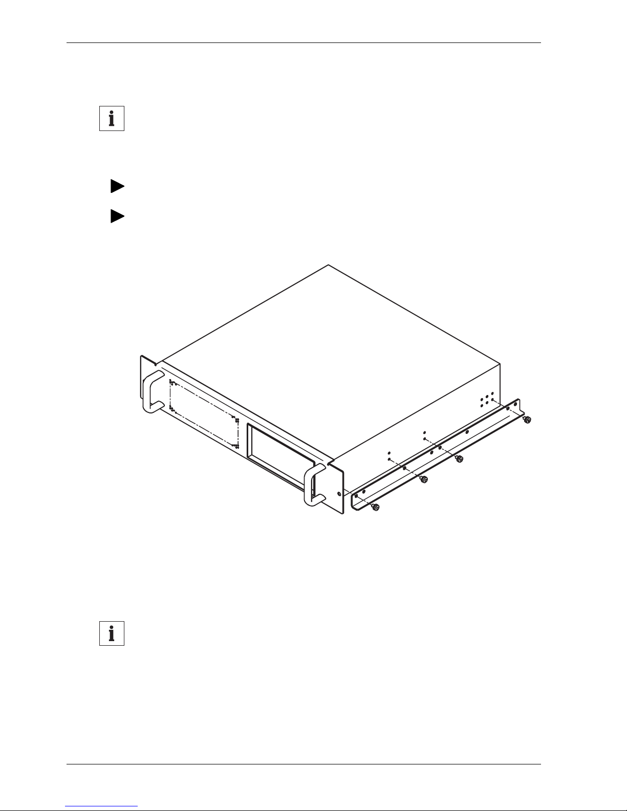
Secure both sides of the device in the cubicle.
If necessary, use the included installation rails. When used, these allow the device to
be easily inserted into and pulled out of a 2 HU installation slot.
Fig. 11: Installing the slide rails on the UPS or battery extension
Slide rails for the installation in cubicles are available as accessories for various cubicle systems. To fix the device in the horizontal position, the front
plate has to be fixed to the 19-inch cubicle at the indicated points on both
sides of the device.
Notice
It is not permissible to fix the device only at the front plate. This may
damage the device and/or other mounted devices.
Page 25
CHLORIDE ACTIVE Installation and commissioning
945040.066 V02OCT/01 GB - 21
G
B
Installing the UPS devices
Notice
When installing the rack-mounting devices (ACTIVE …-19), observe
the additional information in chapter “Installation notes for rackmounting devices” on page GB - 19.
Unpack the device and place it on a solid, horizontal base.
Do not stack multiple devices or battery packs on top of one another. Do not place other objects on the device.
Connect the UPS to an earthing-contact socket (PE) at (AC INPUT).
Danger
As soon as the UPS is connected to the AC mains supply, voltage is
available at the output sockets (AC OUTPUT), even when the UPS
is not switched on via the button on the front side.
The "MAINS" and "BYPASS" LEDs illuminate.
Danger
Keep the air inlet and outlet openings on the rear and front sides of
the device free of obstruction. Do not operate the device or the battery packs upside down or on their sides.
Notice
For proper operation of the UPS, use onl y the supplied connection
cables. The total length of the connection cables at the UPS output
must not exceed 10 m.
The devices are provided with phase detection. If the "MAINS" LED flashes:
pull out the mains plug, turn it 180 degrees and plug it back into the mains socket.
The "MAINS" LED now illuminates permanently.
Page 26
Installation and commissioning CHLORIDE ACTIVE
GB - 22 V02OCT/01 945040.066
Commissioning the UPS devices
Upon connection to mains, the batteries in the UPS are charged automa tically.
Before using the device, charge the batteries for 6 hours.
You may use the UPS immediately without charging the batteries, however
the specified maximum backup time (or discharge time) is not yet available.
After charging, connect your loads to the UPS.
Notice
Do not connect any devices which overload the UPS or which draw
direct current from the UPS (e.g. hair dryer, vacuum cleaner).
If an interface (RS 232 / USB) is used:
Connect the connection cable (accessory) between the UPS and the computer system.
Observe any additional notices provided in the material supplied with you r
accessory.
Switch on your loads.
Now switch on the UPS by pressing the button on the front side.
In addition to the "MAINS" and "BYPASS" indicators, the "LOAD" (output
load) indicator now illuminates. After a few seconds, the "INVERTER" indicator also illuminates and the "BYPASS" indicator extinguishes. The UPS
now operates in online operation.
Danger
If the "LOAD" indicator (output load) displays more than 100 % and
an acoustical warning (1 signal tone/second) sounds, too many loads
are connected to the UPS. If only one load has been connected to
the UPS, the power requirement exceeds the nominal power of the
UPS and a larger UPS must be used.
Notice
UPS devices can also be commissioned without the presence of
mains voltage. The batteries should, however, be sufficiently
charged (see above).
Page 27
CHLORIDE ACTIVE Installation and commissioning
945040.066 V02OCT/01 GB - 23
G
B
Notice
On delivery, the nominal voltage of the UPS devices is 230 V. Using
software, the output voltage of the UPS can be set to other values
(see Table 7 on page GB - 39). The required software can be downloaded from the CHLORIDE Internet page (http://www.chloridepower.com).
Commissioning of an external battery extension
The table below contains an overview of the designations of the battery
extensions available for the UPS devices.
Upright devices: A maximum of two
battery extensions may be connected
to a UPS device.
Rack-mounting devices: A maximum of two
battery extensions may be
connected to the ACTIVE 1000-19 UPS device and five battery extensions
to the ACTIVE 2000-19 and ACTIVE 3000-19 UPS devices.
Danger
Make certain that the circuit b reaker on the battery extension is in the
"OFF" position.
For models ACTIVE 1000(-19) to ACTIVE 3000(-19), connect the battery extension to
the UPS using the supplied cable.
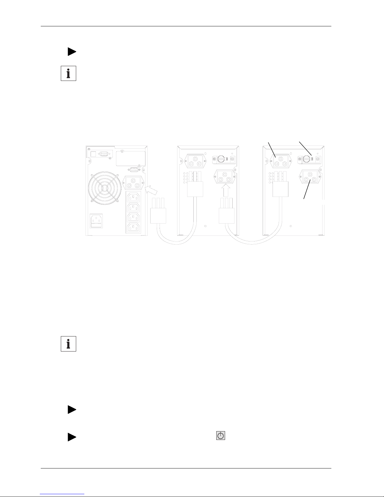
The arrangement of the connection cable is shown i n the following figures
using the upright device as an example.
UPS model Battery extension model Battery used
Maximum number which
may be connected
ACTIVE 700 not possible
ACTIVE 1000 BPACTIVE1000 2 x (3 x 7.0 Ah) 2 pieces
ACTIVE 2000 BPACTIVE3000 2 x (8 x 7.0 Ah) 2 pieces
ACTIVE 3000 BPACTIVE3000 2 x (8 x 7.0 Ah) 2 pieces
ACTIVE 700-19 not possible
ACTIVE 1000-19 BPACTI VE1000-19 2 x (3 x 7.0 Ah) 2 pieces
ACTIVE 2000-19 BPACTIVE2000-19 1 x (8 x 7.0 Ah) 5 pieces
ACTIVE 3000-19 BPACTIVE3000-19 1 x (8 x 7.0 Ah) 5 pieces
Table 5: Battery extensions (maximum expansion)
Page 28
Installation and commissioning CHLORIDE ACTIVE
GB - 24 V02OCT/01 945040.066
Move the circuit breaker on the battery extension to the "ON" position.
Notice
When operating with an external battery extension, the charging
process requires additional time.
Connecting battery extension using the ACTIVE 1000 through
ACTIVE 3000 as an example:
Fig. 12: Connection of battery extensions
Special information for ACTIVE 2000-19 and
ACTIVE 3000-19
Notice
Please note that the ACTIVE 2000-19 and ACTIVE 3000-19 devices
do not contain internal batteries. Therefore, during commissioning of
the first connected BPACTIVE3000-19 battery, they do not provide
protection against mains failure!
If no battery is connected to the device, an alarm is output.
To cancel the alarm, move the battery circuit breaker to the "ON" position or connect
the battery.
Then acknowledge the alarm by pressing the button.
ACTIVE 1000, ACTIVE 2000
or ACTIVE 3000
Battery
extension 1
Battery
extension 2
Battery plug 1
Battery plug 2
Circuit breaker
Page 29
CHLORIDE ACTIVE Installation and commissioning
945040.066 V02OCT/01 GB - 25
G
B
Now it is possible to switch to online operation by pressing the button.
The device again tests the battery voltage (device beeps) and remains in
bypass mode until a constant battery voltage is present.
Notice
If more than one battery extension is connected to the ACTIVE 200019 and ACTIVE 3000-19 devices, the actual number of battery extensions is to be set as described in the following section “Adjusting
the number of external battery extensions” .
Adjusting the number of external battery extensions
Notice
The UPS calculates the available battery capacity. For a correct calculation, it is necessary to set the number of externally connected
battery extensions. Proceed as follows:
Press the button to switch the UPS to BYPASS operation.
Press the button again and do not release it until the UPS emits an acoustical
signal.
After you have released the button, all LEDs on the "BATTERY" indicator
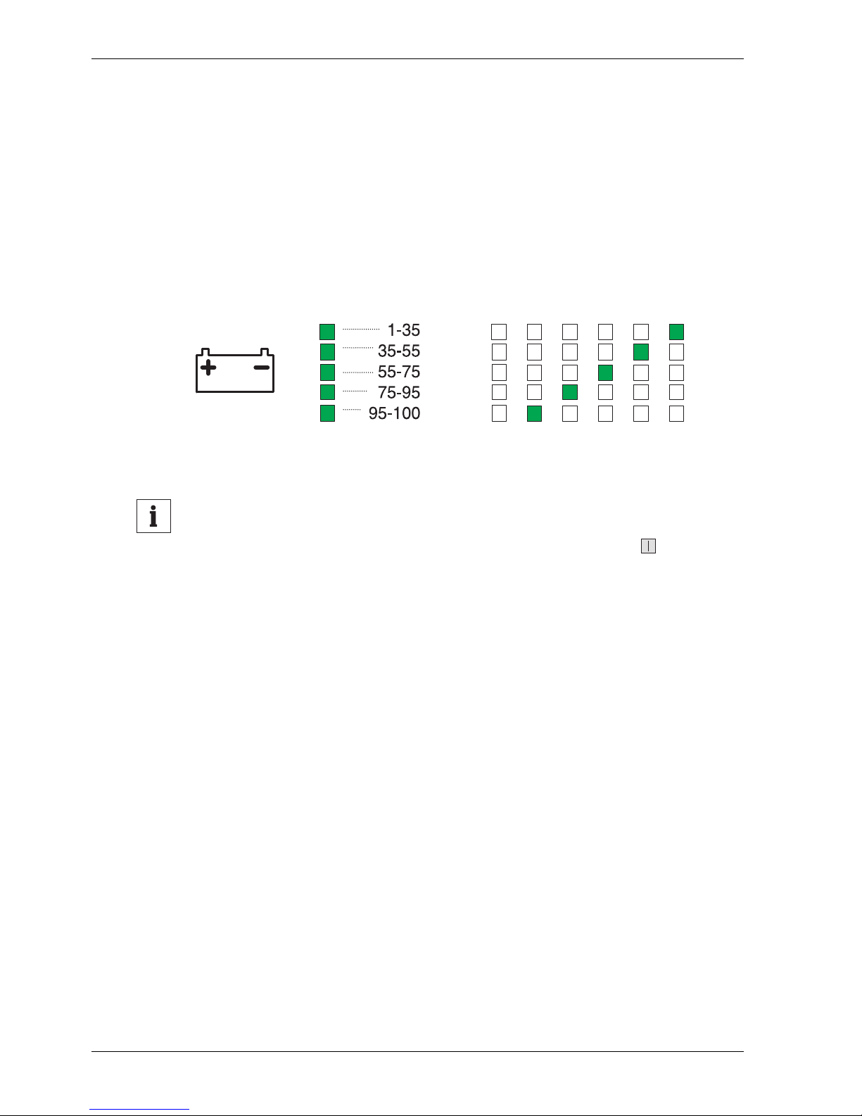
flash twice. The current setting for the number of externally connected battery extensions is then displayed. The possible displays are shown in the figure below.
You can now select the number of connected external battery extensions by pressing
the button multiple times.
Notice
If you do not press the button within 3 seconds, the UPS exits the
mode and you must restart the adjustment procedure.
Once the correct number of connected external battery extensions is displayed, the information must be saved.
To do this, press the button and keep pressed down until an acoustical signal
tones.
The adjustment procedure is now concluded.
Page 30
Installation and commissioning CHLORIDE ACTIVE
GB - 26 V02OCT/01 945040.066
The following graphic shows the displays of the BATTERY LED strip possible while setting the number of external battery extensions:
Fig. 13: Number of external battery extensions
Notice
Upon conclusion of the adjustment procedure, the UPS is in bypass
operation. Switch the UPS to online operation by pressing the button for at least 1 second.
Capacity in %
0
B
a
t
te
r
y
e
x
t
e
n
s
i
o
n
s
1
B
a
t
te
r
y
e
x
te
n
s
i
o
n
2
B
a
tt
e
r
y
e
x
t
e
n
s
i
o
n
s
3
B
a
t
t
e
r
y
e
x
t
e
n
s
i
o
n
s
4
B
a
tt
e
r
y
e
x
t
e
n
s
i
o
n
s
5
B
a
tt
e
r
y
e
x
t
e
n
s
i
o
n
s
Page 31

CHLORIDE ACTIVE Operational behaviour
945040.066 V02OCT/01 GB - 27
G
B
Operational behaviour
Checking the operational readiness
Now disconnect the UPS from the mains supply in order to check the mains backup
function.
If functioning properly and if batteries are charged, a signal ton e should be
audible in 4-second intervals. The "MAINS" LED (mains voltage) extinguishes. If the pause between the signal tones shortens to 1 second, the
UPS can continue to provide power for a maximum of 3 minutes before it
automatically shuts down.
Your computer system is powered by the batteries up until the end of the
backup time. If this is not the case, refer to chapter “Troubleshooting” on
page GB - 37.
Reconnect the UPS to mains.
Your UPS is now again ready for operation. Note that the batteries must be
recharged before the full backup time is again available.
Automatic test
Lamp test
While the device is connected to mains, press the button for at least 1 second in
order to switch the device to bypass operation.
Notice
The supplied load is not protected from mains disturbances in this
operating mode!
The input is confirmed by a single acoustical signal.
Then press the button for at least 1 second in order to switch the device back to
online operation.
The elements of the "BATTERY" LED strip indicate the corresponding
charging state of the battery. The "MAINS" and "INVERTER" indicators illuminate.
Page 32

Operational behaviour CHLORIDE ACTIVE
GB - 28 V02OCT/01 945040.066
Initially, all elements of the "LOAD" LED strip illuminate. Beginning with the
1 - 35 % indicator, the remaining elements in this LED strip are extinguished
one after the other. Afterward, the elements which correspond to the load
state of the device illuminate.
After approx. 5 seconds, the "BYPASS" indicator extinguishes and the
"INVERTER" indicator illumi nates. The connected loads are supplied fro m
the mains supply via the inverter.
Battery test
The device must be in online operation.
With the device connected to mains, press the button for at least 1 second.
• The input is confirmed by a single acoustical signal, and the connected
load is now supplied by the battery for 10 seconds.
• The elements of the "BATTERY" LED strip correspond to the charging
state of the battery and the "LOAD" LED strip corresponds to the load
factor. The "MAINS" and "INVERTER" indicators illuminate. An acoustical signal sounds during the test (as in battery operation of the UPS).
• If the test has been completed successfully, the "BATTERY" LED strip
ceases to flash after approx. 10 seconds and the UPS returns to online
operation. If a problem exists with the batteries, an alarm is triggered.
Page 33
CHLORIDE ACTIVE Operational behaviour
945040.066 V02OCT/01 GB - 29
G
B
Operating modes
The UPS has three different operating modes when it is switched on.
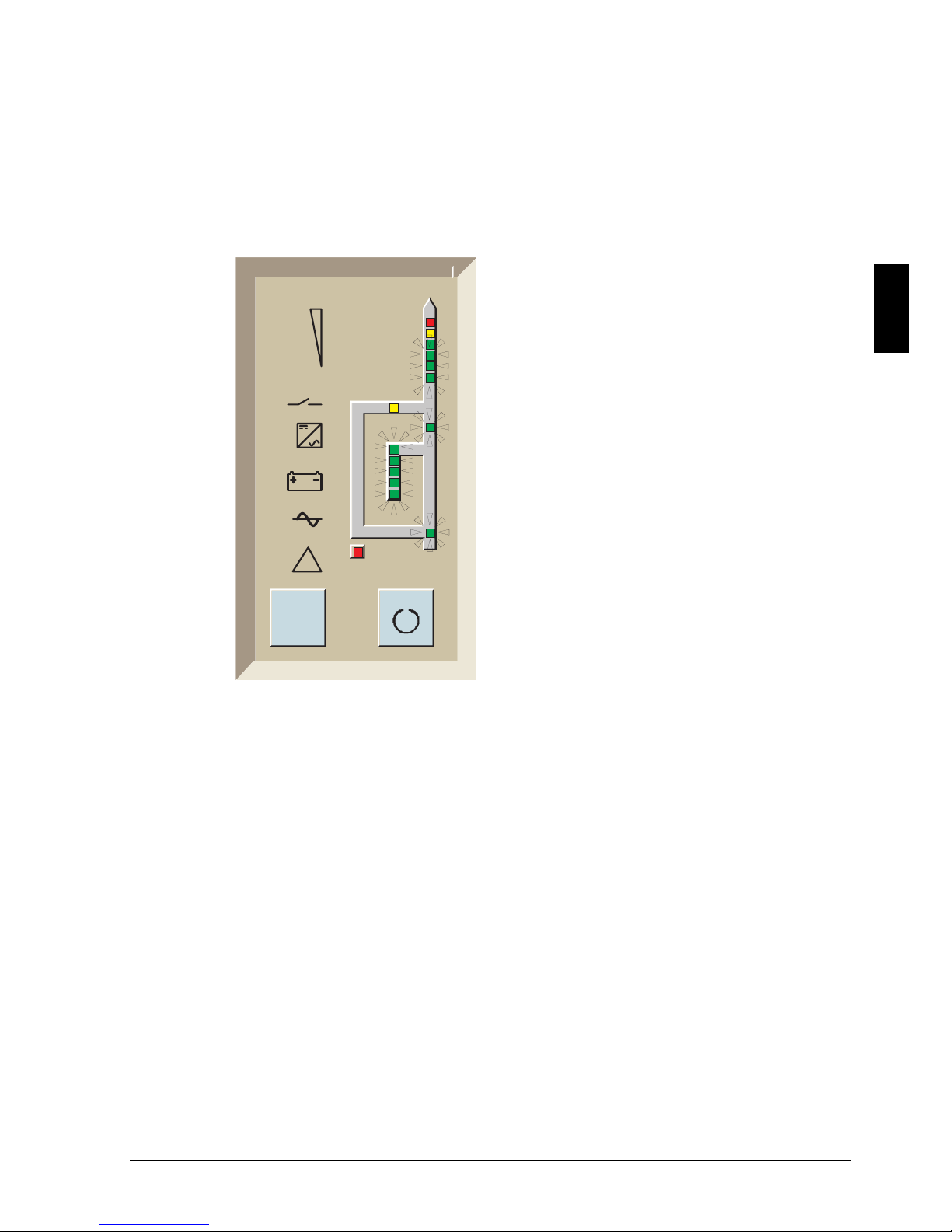
Normal operation (mains supply present)
The loads are supplied directly from
mains via the inverter.
I
I
!
Fig. 14: UPS control panel in normal
operation
Page 34
Operational behaviour CHLORIDE ACTIVE
GB - 30 V02OCT/01 945040.066
Battery operation (mains failure)
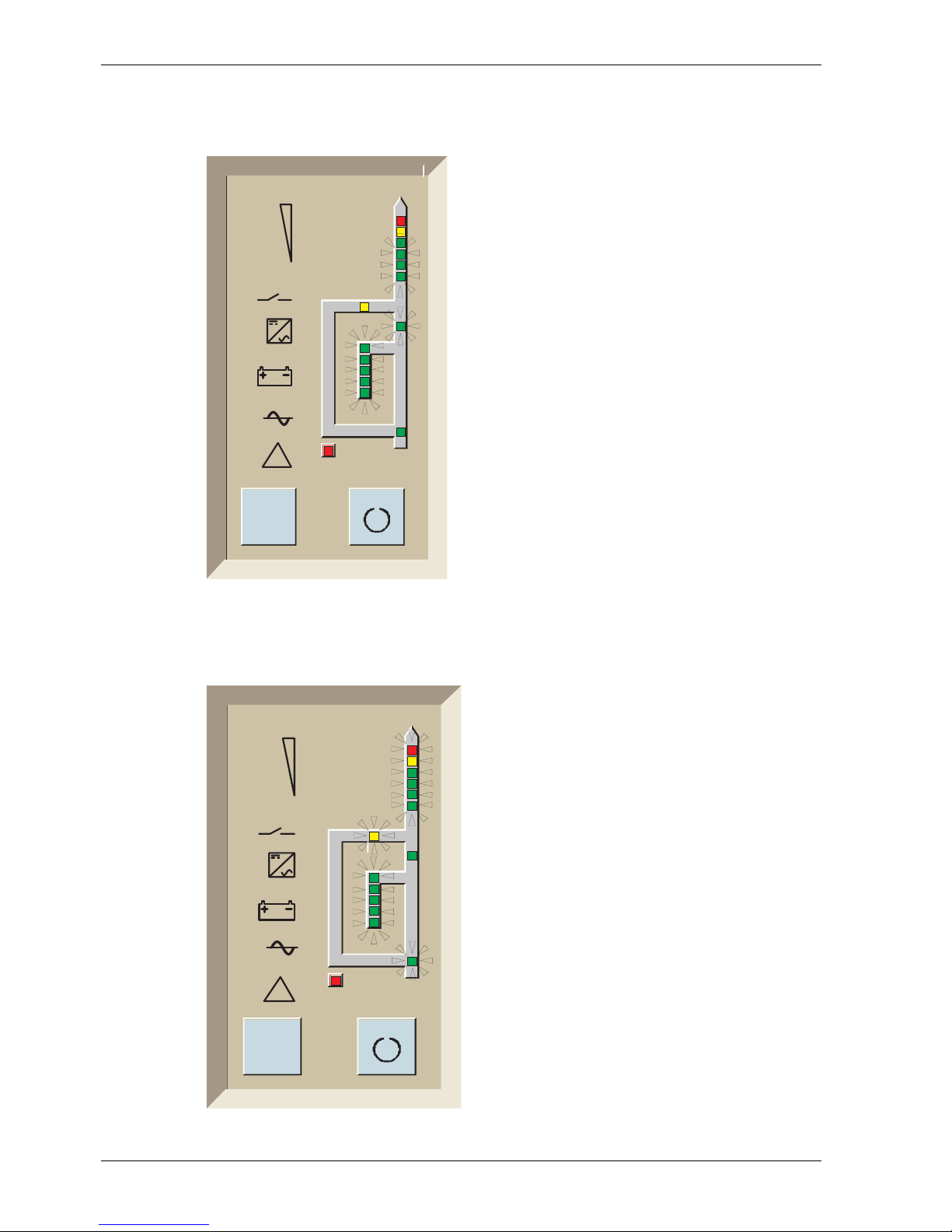
In the event of a mains failure, the
inverter supplies the loads without interruption; the power is supplied by the
battery.
In this operating mode, an acoustical
sound is emitted in intervals of approx.
4 seconds. If the minimum power level
of the battery is reached, the signal is
emitted every second.
Bypass operation (overload > 130 %)
In the event of a large overload
(> 130 %), the device switches to
bypass and the inverter is blocked.
Power is supplied by the mains supply.
This is not a normal operating state. If
the mains supply fails, the loads are no
longer supplied (no UPS operation).
I
I
!
Fig. 15: UPS control panel in battery
o
peration
I
I
!
Fig. 16: UPS control panel in bypass
op
eration
Page 35

CHLORIDE ACTIVE Interface description
945040.066 V02OCT/01 GB - 31
G
B
Interface description
The UPS provides a COM 3 standard interface, a USB and an optional COM
interface. These combine protocol-data transfer via a serial RS 232 interface or USB interface and the signal exchange via a contact interface (UPS
interface). Moreover, an interface is provided for controlling switchable load
distributors (ECO).
The interfaces can be used for:
• direct communication between UPS and computer
• integrating the UPS as a client into a network with central monitoring
(SNMP)
• passing on operating states to external message systems
• load management by means of switchable load distributors
The necessary communication software packets, interface cards and extension modules are available as accessories.
COM 3 standard interface
The 9-pin Sub-D connection (pin contacts) carries the RS 232 signals.
Fig. 17: COM 3 interface
2
3
4
7
8
1
9
6
5
RxD
TxD
8 ... 10 V
SGN
Page 36

Interface description CHLORIDE ACTIVE
GB - 32 V02OCT/01 945040.066
The COM 3 interface is ele ctri c a l ly isolated from all other current circuits.
• SGN at pin 5
This connection is the reference point for all signals.
• RXD at pin 2 and TXD at pin 3
correspond to the normal assignment of an RS 232 interface.
• In addition, an isolated auxiliary voltage is made available at pin 7
(+8…+10VDC).
USB interface
As with the COM 3 standard interface, the USB interface facilitates the protocol-data transfer. A standard communication cable can be used for establishing communication between the UPS and PC. If the USB interface is
used for communication purposes, the COM 3 interface is not operational.
Optional COM interface
The optional COM interface can be fitted with various i nterface cards. The
code located next to the plug is then dependent on the interface card model.
A detailed description is included with the various interface cards, which are
available as accessories.
Possible interface cards: SNMP adapter cards for integrating the devices
into a network or potential-free signalling contacts as per COM 1 (SIC
assembly). Observe the installation instructions included with the accessory.
Described below is the function of the interface signals in the COM 1 variant.
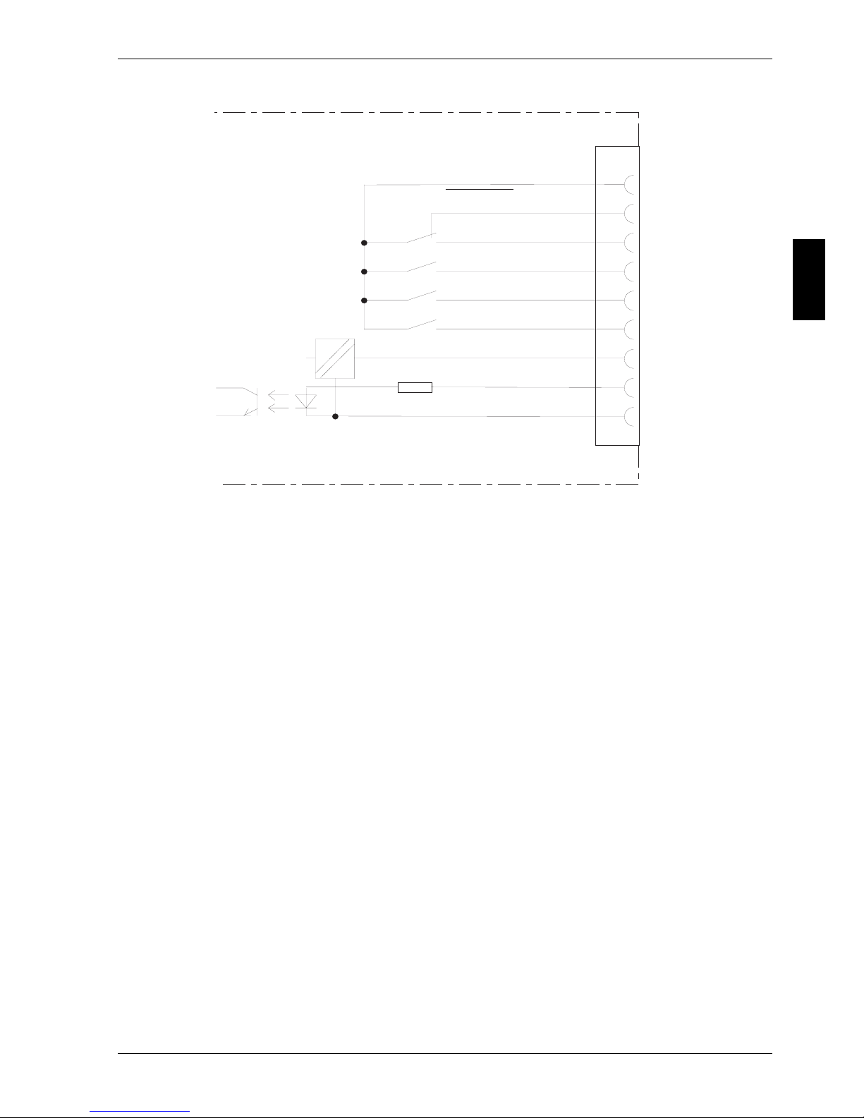
The optional COM 1 interface makes available potential-free signalling contacts, a shutdown input an d an isolated auxiliary voltage.
Page 37
CHLORIDE ACTIVE Interface description
945040.066 V02OCT/01 GB - 33
G
B
Fig. 18: COM 1 interface
INV SHUTDOWN
This input (pin 6: high signal +5 V … +12 V, t 1 s, pin 7: 0 V) makes it possible for the control computer to switch off the UPS in the event of a mains
failure. Upon mains restoration, the UPS starts independent of this signal
state.
AC FAIL
(N.O. between pins 2 and 4, N.C. between pins 3 and 4)
This signal is active when the mains voltage at the UPS input is not present
for at least 10 seconds or the mains voltage exits the tolerance range. The
signal is cancelled 850 ms following mains restoration.
BATT LOW
(N.O. between 5 and 4)
This output is active when the battery can continue to supply curren t at the
nominal load for only approx. 3 minutes.
=
=
4
3
2
5
1
8
9
6
7
COMMON
AC FAIL
AC FAIL
BATT LOW
BYPASS ACTIVE
SUM ALARM
INV SHUTDOWN
12V
GND
COM 1
Page 38

Interface description CHLORIDE ACTIVE
GB - 34 V02OCT/01 945040.066
BYPASS ACTIVE
(N.O. between 1 and 4)
This signal is active when the device has been switched to bypass, the
inverter is blocked and the power is supplied from the mains supply.
SUM ALARM
(N.O. between 8 and 4)
This output is active when one of the messages "AC FAIL", "BATT LOW" or
"BYPASS ACTIVE" has been output or the "ALARM" display on the front
side illuminates.
The contact rating of the signalling contacts is 1 A / 24 V DC or
1A / 120VAC.
In addition, an isolated auxiliary voltage 12 V DC is made available (pi n 9:
+12 V, 50 mA; pin 7: GND)
EXT. OUTLETS CONTROL interface
The UPS is capable of switching specific connected loads through the EXT.
OUTLETS CONTROL interface. In combination with an output distributor
(ECO), available as an accessory, it is thus possible to operate a load management system. For a description of the functionality, please refer to the
operating instructions included with the output distributor.
Page 39

CHLORIDE ACTIVE Maintenance
945040.066 V02OCT/01 GB - 35
G
B
Maintenance
The UPS requires no maintenance by the user. When the usable lifetime of
the battery has expired, the UPS and the battery connections eventually
connected must be replaced by the responsible customer service representative.
As a rule, the usable lifetime of the battery is 4 years at 25°C ambient temperature; it is, however, dependent on the frequency and duration o f mains
failures.
The device indicates that the battery usable lifetime has expired by flashing
the "BATTERY" LED strip. The flash frequency is approx. 0.25 Hz
(2 seconds on and 2 seconds off). In addition, an acoustical signal is emitted
every minute.
Check whether the backup time of the UPS is still adequate for your application (see
"Checking the operational readiness") in regular intervals (6 … 12 months).
Storage
When storing for longer periods in regi ons with mo derate cli mate s, the batteries should be charged every 3 months for 5 hours. In areas with high er
temperatures, this interval should be reduced to 2 months.
Connect the UPS, as described in chapter “Installation and commissioning”, to an
earthing-contact socket. For the models with permanent connection, switch on the input circuit breaker located on the rear side of the device.
After 5 hours, pull out the mains plug and uninstall the UPS in reverse order of that
described in chapter“Installation and commissioning”.
Record the charging date, e.g. on the packaging.
Page 40

Maintenance CHLORIDE ACTIVE
GB - 36 V02OCT/01 945040.066
Cleaning
Danger
Risk of electrical shock during cleaning an operationally ready UPS
Switch off the UPS by pressing the button and pull the mains plug out of the socket.
When cleaning, do not use scouring agents or cleaning agents which are
damaging to plastics.
Make certain that no fluids enter the interior of the UPS.
Make certain that the ventilation slits on the UPS remain open.
The surface of the UPS housing can be cleaned with either a dry or damp
cloth.
Page 41

CHLORIDE ACTIVE Troubleshooting
945040.066 V02OCT/01 GB - 37
G
B
Troubleshooting
If, in spite of the high reliability of this device, problems should occur, please
check the following points before contacting the responsible customer service representative:
• Is the mains voltage present at the UPS input?
• Is the input fuse defective or have circuit brea kers tripped?
If you contact the responsible customer service representative, please have
the following information ready:
• Device information = model, order no., series no. as per nameplate
• An exact description of the problem (what loads are being operated,
does the problem occur regularly or sporadically etc.)
Problem Possible cause Measure
No display
No alarm
(UPS switched off)
Main switch switched off Switch on main switch
No mains voltage present
Have mains inspected by qualified
electrician
Input fuse defective or input
circuit breaker tripped
Replace with fuse of same type or
switch on circuit breaker. If the problem persists, contact the responsible
customer service representative.
MAINS indicator does
not illuminate, acoustical alarm sounds in
intervals
No mains voltage present
UPS operation (see “Operational
behaviour” on page GB - 27)
MAINS indicator flashes
Phase and neutral lines
swapped at UPS input.
Pull out mains plug and plug back in
correctly (see “Installing the UPS
devices” on page GB - 21)
MAINS indicator does
not illuminate when
mains voltage present,
acoustical alarm sounds
in intervals
Input fuse defective or input
circuit breaker tripped
Replace with fuse of same type or
switch on circuit breaker. If the problem persists, contact the responsible
customer service representative.
ALARM indicator illuminates, acoustical alarm
sounds continuously
UPS error
Contact the responsible customer
service representative
Overheating Decrease ambient te mperature
Table 6: Rectification of errors
Page 42

Troubleshooting CHLORIDE ACTIVE
GB - 38 V02OCT/01 945040.066
Backup time less than
that specified
The fuse switch of the battery
extension(s) is in the "OFF"
position.
Move the fuse switch to the "ON"
position.
The number of externally connected battery extensions was
set incorrectly.
Correct settings (see “Commissioning of an external battery extension”
on page GB - 23)
Batteries are not completely
charged
Charge batteries (see “Commissioning the UPS devices” on page GB -
22) and test backup time. If the problem persists, contact the responsible
customer service representative.
Batteries are defective Contact customer service
Charging device is defective Contact customer service
OVERLOAD LED illuminates
Overload at UPS output Reduce load to the permissible value
No communication
between UPS and PC
Wrong serial connection cable
Check whether the correct cable has
been used (standard modem/null
modem cables are not permissible)
Interface on the PC is being
used by another process or is
defective.
Check whether other software/service is accessing the interface on the
PC; try selecting a different serial
interface.
Interference on the data cable Lay cable differently.
Problem Possible cause Measure
Table 6: Rectification of errors
Page 43
CHLORIDE ACTIVE Technical data
945040.066 V02OCT/01 GB - 39
G
B
Technical data
Technical data for the models ACTIVE 700 to
ACTIVE 3000
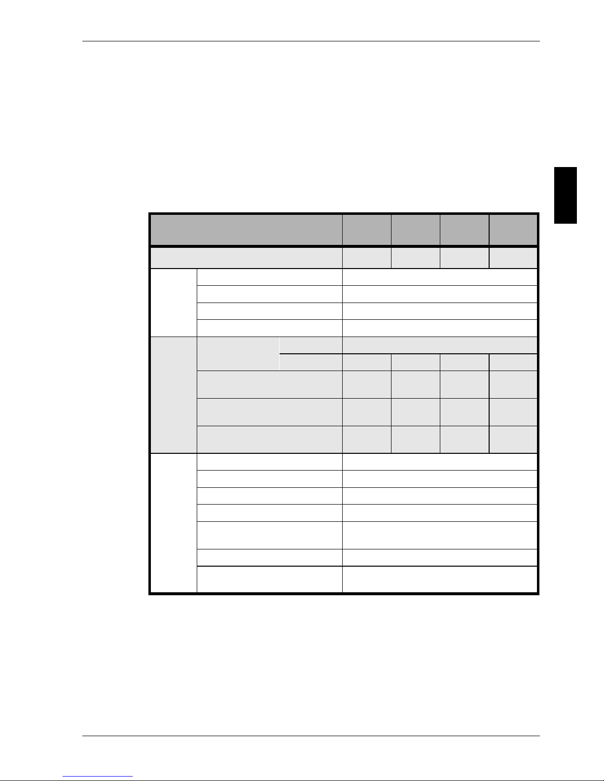
UPS model
ACTIVE
700
ACTIVE
1000
ACTIVE
2000
ACTIVE
3000
Power
700 VA 1 kVA 2 kVA 3 kVA
Input
Voltage 1 N AC 220/230/240V
Voltage range 160 V to 276 V
Frequency 50/60Hz ± 5%, automat. frequency detection
Power factor (lambda) 0,95
Battery
Integrated battery
Model Lead, maintenance free
Voltage/V 24 36 96 96
Autonomy time,
half-load/full-load/min
12/6 15/7 24/10 14/6
Autonomy time, 1 battery extension half-load/full-load/min
56/28 84/37 52/25
Autonomy time, 2 battery extensions half-load/full-load/min
105/48 157/69 97/43
Output
Voltage 1 N AC 220,230,240 V
Voltage tolerance ± 3%
Frequency line-clocked see Input frequency
Frequency self-clocked 50/60Hz ± 0.5%
Harmonic distortion
(linear/non-linear load)
max. 4% / max. 8%
Perm. crest factor 3
Overload capacity
130% for 1.5 sec, 110% for 10 sec
Output is short-circuit proof
Table 7: Electrical data (ACTIVE 700 to ACTIVE 3000)
Page 44
Technical data CHLORIDE ACTIVE
GB - 40 V02OCT/01 945040.066
UPS model
ACTIVE
700
ACTIVE
1000
ACTIVE
2000
ACTIVE
3000
Electrical safety EN 50091-1; EN 60950
Radio interference level EN 50091-2, Class B
Emitted interference EN 50081-1
Interference immunity
EN 50082-1
IEC 801-2,Level 4 / IEC 801-3,Level 3
IEC 801-4,Level 4 / IEC 801-5,Level 3
Mains pollution EN 61000-3-2, EN 61000-3-3
Efficiency > 83 % 90 %
Degree of protection IP20
Cooling Fan
Noise level
in dB(A), typical
Mains operation, <39 <39 <45 <45
battery operation <40 <40 <46 <46
Perm. ambient temperature during operation
10°C to + 40°C
recommended +15°C to + 32°C
Perm. ambient temperature during storage -15°C to + 40°C
Perm. rel. humidity during operation 20% to 90%, no condensation perm.
Installation altitude
max. 3000m, from 1500m max.
Ambient temperature = 35°C
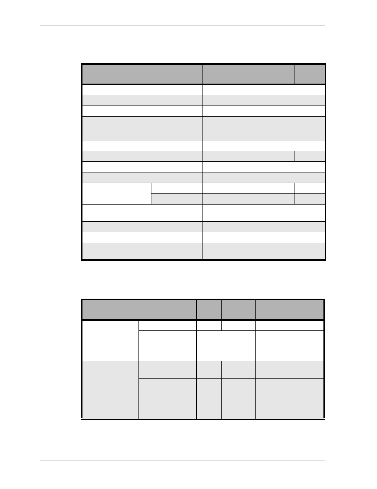
Table 8: General data (ACTIVE 700 to ACTIVE 3000)
UPS model
ACTIVE
700
ACTIVE
1000
ACTIVE
2000
ACTIVE
3000
UPS
Weight / kg 11,5 14 33 33
Dimensions / mm
Width
Height
Depth
145
225
405
200
350
405
Battery extension
Model
BPACTIVE
1000
BPACTIVE
3000
BPACTIVE
3000
Weight / kg 19 48 48
Dimensions / mm
Width
Height
Depth
145
225
405
200
350
470
Table 9: Mechanical data (ACTIVE 700 to ACTIVE 3000)
Page 45
CHLORIDE ACTIVE Technical data
945040.066 V02OCT/01 GB - 41
G
B
UPS model
ACTIVE
700
ACTIVE
1000
ACTIVE
2000
ACTIVE
3000
Mains connection
Model IEC 320 IEC320
Nominal current 10 A 16 A
Fuse protection of mains supply 6 A 10 A 12 A 16 A
Load connection
Number 4 4 4 2
Model IEC 320 IEC 320 IEC 320 IEC 320
Nominal current 10 A 10 A 10 A 16 A
COM 3 interface SUB-D, 9 pin, pins
USB interface USB, type B
COM interface (optional) SUB-D, 9 pin, socket
EXT. OUTLETS CONTROL interface SUB-D, 9 pin, socket
Battery extension none plug, 3 pin
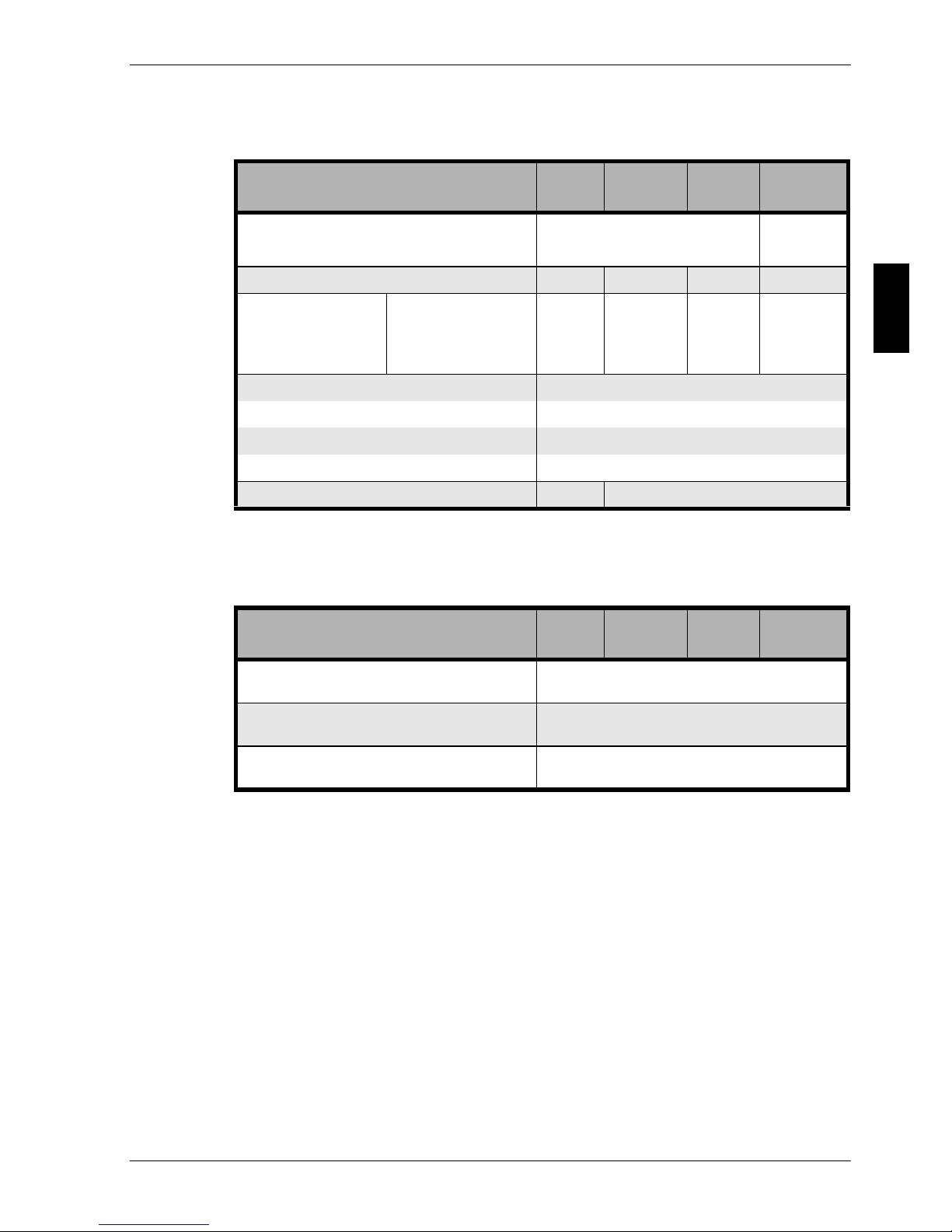
Table 10: Connections (ACTIVE 700 to ACTIVE 3000)
UPS model
ACTIVE
700
ACTIVE
1000
ACTIVE
2000
ACTIVE
3000
Signalling
LED indicator on front side
Acoustical alarm
Message
Message contacts, see SIC option
Interface RS 232/USB
Operation
Signal input, see SIC option
Interface RS 232/USB
Table 11: Other data (ACTIVE 700 to ACTIVE 3000)
Page 46
Technical data CHLORIDE ACTIVE
GB - 42 V02OCT/01 945040.066
Technical data for the models ACTIVE 700-19 to
ACTIVE 3000-19
UPS model
ACTIVE
700-19
ACTIVE
1000-19
ACTIVE
2000-19
ACTIVE
3000-19
Power
700 VA 1 kVA 2 kVA 3 kVA
Input
Voltage 1 N AC 230 V
Voltage range 160 V to 276 V
Frequency 50/60Hz ± 5%, automat. frequency detection
Power factor (lambda) 0,95
Battery
Integrated battery
Model
Lead, maintenance
free
External battery exten-
sions only
Voltage/V 24 36 96 96
Autonomy time,
half-load/full-load/min
12/6 15/7
Autonomy time, 1 battery extension half-load/full-load/min
56/28 24/10 14/6
Autonomy time, 2 battery extensions half-load/full-load/min
105/48 51/24 31/14
Output
Voltage 1 N AC 220,230,240 V
Voltage tolerance ± 3%
Frequency line-clocked see Input frequency
Frequency self-clocked 50/60Hz ± 0.5%
Harmonic distortion
(linear/non-linear load)
max. 4% / max. 8%
Perm. crest factor 3:1
Overload capacity
> 130% for 1,5 sec, ~ 4 periods
> 110% for 10 sec
Output is short-circuit proof
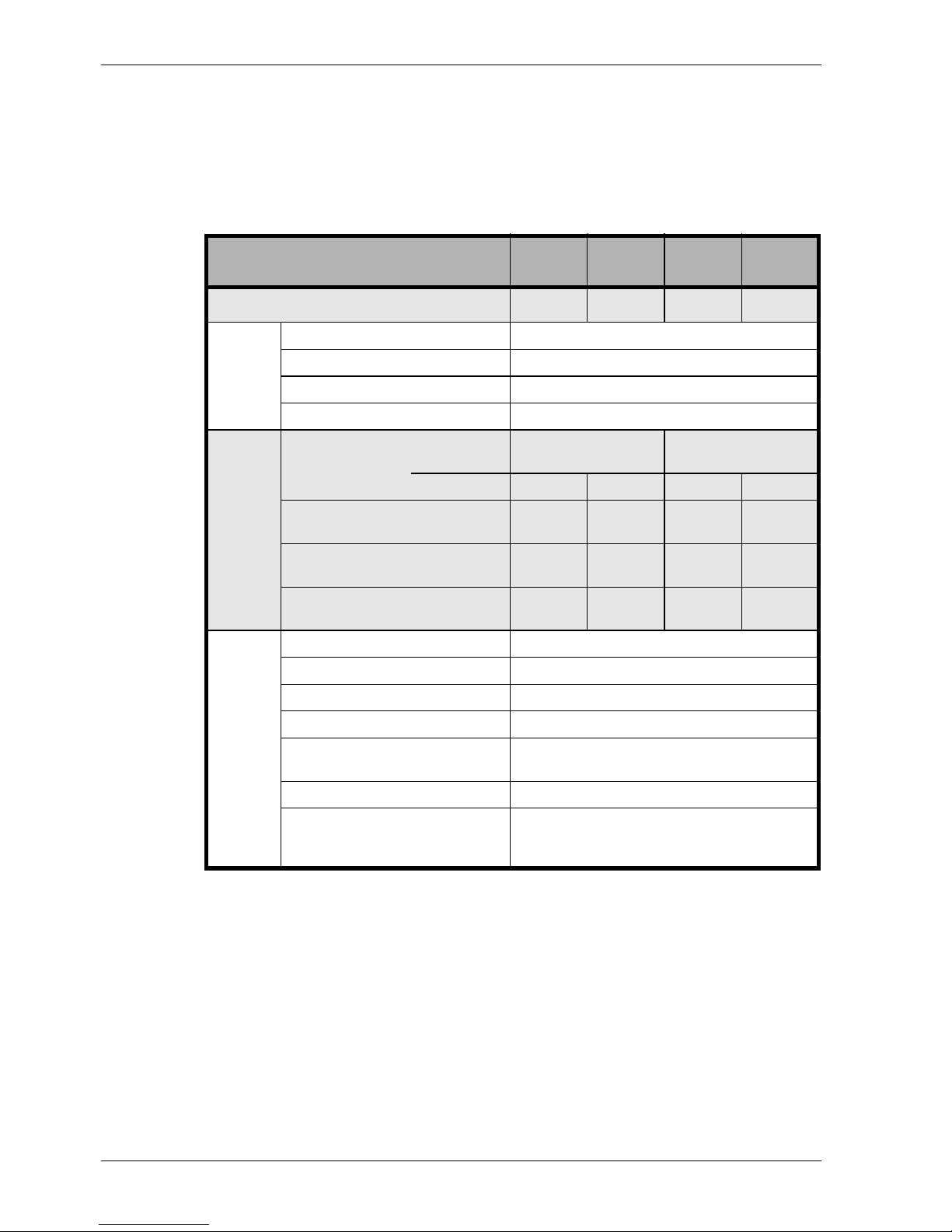
Table 12: Electrical data (ACTIVE 700-19 to ACTIVE 3000-19)
Page 47
CHLORIDE ACTIVE Technical data
945040.066 V02OCT/01 GB - 43
G
B
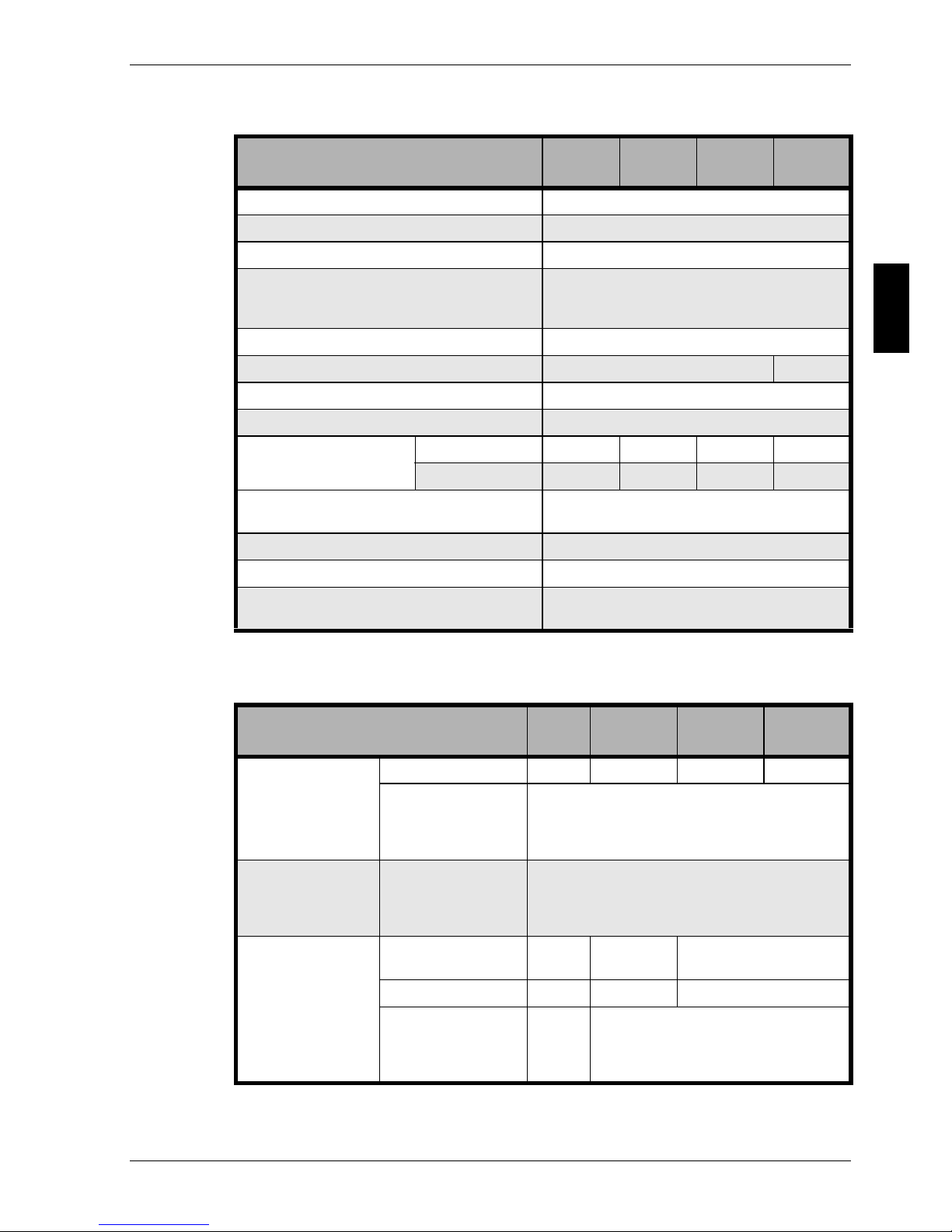
UPS model
ACTIVE
700-19
ACTIVE
1000-19
ACTIVE
2000-19
ACTIVE
3000-19
Electrical safety EN 50091-1; EN 60950
Radio interference level EN 50091-2, Class B
Emitted interference EN 50081-1
Interference immunity
EN 50082-1
IEC 801-2,Level 4 / IEC 801-3,Level 3
IEC 801-4,Level 4 / IEC 801-5,Level 3
Mains pollution EN 61000-3-2, EN 61000-3-3
Efficiency > 83 % 90 %
Degree of protection IP20
Cooling Fan
Noise level
in dB(A), typical
Mains operation, 40 dB 40 dB 46 dB 46 dB
battery operation 40 dB 40 dB 46 dB 46 dB
Perm. ambient temperature during operation
10°C to + 40°C
recommended +15°C to + 32°C
Perm. ambient temperature during storage -15°C to + 40°C
Perm. rel. humidity during operation 20% to 90%, no condensation perm.
Installation altitude
max. 3000m, from 1500m max.
Ambient temperature = 35°C
Table 13: General data (ACTIVE 700-19 to ACTIVE 3000-19)
UPS model
ACTIVE
700-19
ACTIVE
1000-19
ACTIVE
2000-19
ACTIVE
3000-19
UPS
Weight / kg 13 16 10 11
Dimensions / mm
Width
Height
Depth
482,6
87
485
Body size
Dimensions / mm
Width
Height
Depth
410
87
412
Battery extension
Model
BPACTIVE
1000-19
BPACTIVE
3000-19
Weight / kg 21,5 27
Dimensions / mm
Width
Height
Depth
482,6
87
448
Table 14: Mechanical data (ACTIVE 700-19 to ACTIVE 3000-19)
Page 48
Technical data CHLORIDE ACTIVE
GB - 44 V02OCT/01 945040.066
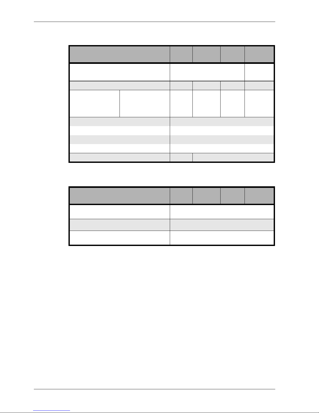
UPS model
ACTIVE
700-19
ACTIVE
1000-19
ACTIVE
2000-19
ACTIVE
3000-19
Mains connection
Model IEC 320 IEC 320
Nominal current 10 A 16 A
Fuse protection of mains supply 6 A 10 A 12 A 16 A
Load connection
Number 4 4 4 1
Model IEC 320 IEC 320 IEC 320 IEC 320
Nominal current 10 A 10 A 10 A 16 A
COM 3 interface SUB-D, 9 pin, pins
USB interface USB, type B
COM interface (optional) SUB-D, 9 pin, socket
EXT. OUTLETS CONTROL interface SUB-D, 9 pin, socket
Battery extension none plug, 3 pin
Table 15: Connections (ACTIVE 700-19 to ACTIVE 3000-19)
UPS model
ACTIVE
700-19
ACTIVE
1000-19
ACTIVE
2000-19
ACTIVE
3000-19
Signalling
LED indicator on front side
Acoustical alarm
Message
Signalling contact +5V … +12V (SIC)
Operation
Signal input +5V … +12V (SIC)
Interface RS 232
Table 16: Other data (ACTIVE 700-19 to ACTIVE 3000-19)
Page 49
CHLORIDE ACTIVE Technical data
945040.066 V02OCT/01 GB - 45
G
B
Usable Battery lifetime
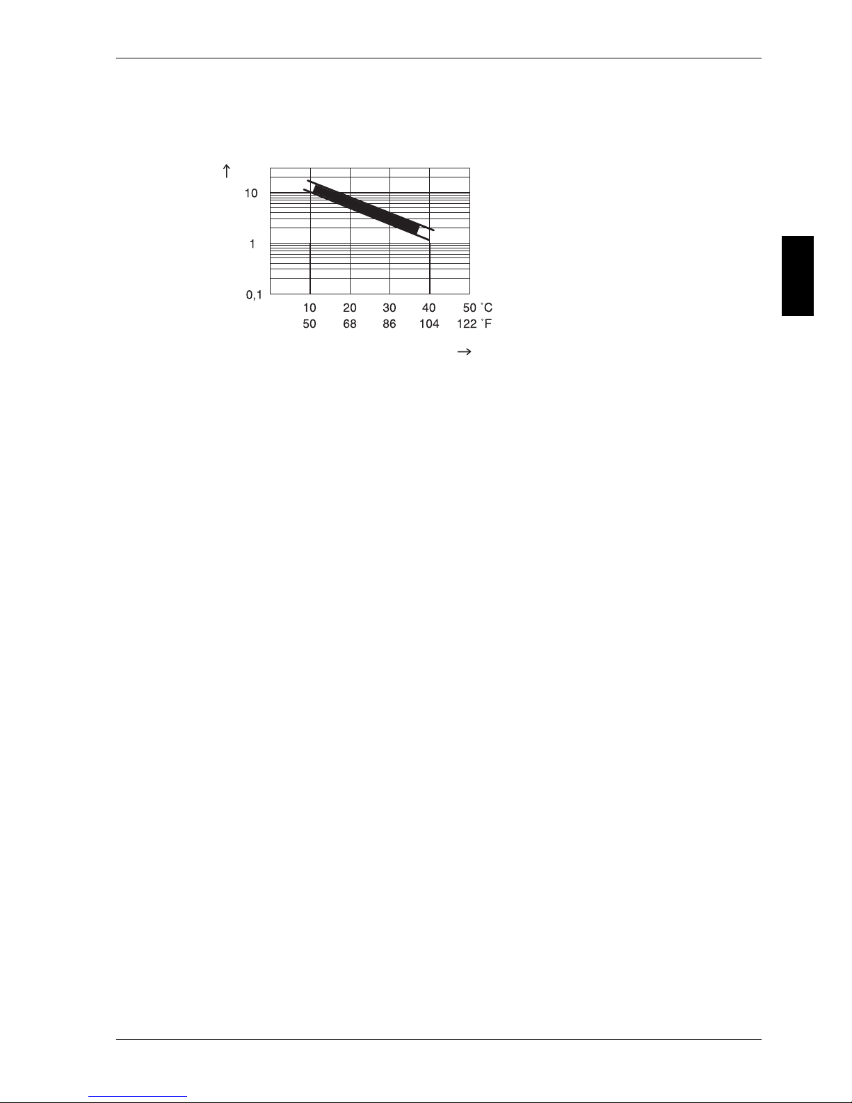
Fig. 19: Usable battery lifetime
The diagram shows the typical usable lif etimes of the batteries used in the
UPS devices (only as a function of the ambient temperature of the devices).
In addition, the usable lifetime is also d ependent on the cyclical u se of the
batteries, i.e. the frequency and duration of mains failures also reduces the
usable lifetimes of the batteries.
Ambient temperature
Usable lifetime / years
Page 50

Technical data CHLORIDE ACTIVE
GB - 46 V02OCT/01 945040.066
Typical battery backup times
By combining UPS and battery extensions (BP), the typical backup times
achieved with new, fully loaded batteries listed in the following table can be
achieved (all listed autonomy times in min).
VA Watt
ACTIVE
700(-19)
ACTIVE
1000(-19)
ACTIVE
1000(-19) + 1 BP
ACTIVE
1000(-19) + 2 BP
100 70 33 63 242 452
200 140 23 36 139 261
300 210 14,5 27 95 178
350 245 12 24 86 152
400 280 10,5 20 71 133
500 350 9 15 56 105
600 420 7 12 46 86
700 490 6 10 39 72
800 560 8,5 33 62
1000 700 72848
Table 17: Backup times ACTIVE 700(-19) and ACTIVE 1000(-19)
VA Watt
ACTIVE 2000
ACTIVE
2000-19
+ 1 BP
ACTIVE
2000-19
+ 2 BP
ACTIVE 2000
+ 1 BP
ACTIVE
2000-19
+ 3 BP
ACTIVE
2000-19
+ 4 BP
ACTIVE 2000
+ 2 BP
ACTIVE
2000-19
+ 5 BP
400 280 62 145 238 338 445
500 350 51 119 193 278 366
600 420 43 100 164 233 307
700 490 36 84 138 196 258
800 560 31 72 119 169 222
1000 700 24 51 84 119 157
1250 875 19 43 71 102 133
1500 1050 16 35 56 80 105
1750 1225 13 28 48 68 89
2000 1400 10 24 37 53 69
Table 18: Backup times ACTIVE 2000(-19)
Page 51

CHLORIDE ACTIVE Technical data
945040.066 V02OCT/01 GB - 47
G
B
VA Watt
ACTIVE 3000
ACTIVE
3000-19
+ 1 BP
ACTIVE
3000-19
+ 2 BP
ACTIVE 3000
+ 1 BP
ACTIVE
3000-19
+ 3 BP
ACTIVE
3000-19
+ 4 BP
ACTIVE 3000
+ 2 BP
ACTIVE
3000-19
+ 5 BP
600 420 38 90 148 210 277
700 490 34 80 131 189 248
800 560 29 70 114 163 216
1000 700 22 54 90 128 168
1250 875 19 42 70 100 131
1500 1050 14 31 52 74 97
1750 1225 13 27 47 67 88
2000 1400 11 24 40 56 73
2250 1575 9 22 35 49 65
2500 1750 7 19 30 44 57
2750 1925 6,5 18 26 39 51
3000 2100 6 14253243
Table 19: Backup times ACTIVE 3000(-19)
Page 52

Technical data CHLORIDE ACTIVE
GB - 48 V02OCT/01 945040.066
Page 53

CHLORIDE ACTIVE CHLORIDE ADDRESSES
945040.066 V02OCT/01 I
CHLORIDE ADDRESSES
CHLORIDE WORLD HEADQUARTERS
Chloride Silectron
Via Fornace 30
40023 Castel Guelfo
Bologna
Italy
Telephone: +39 054 2632 111
Facsimile: +39 054 2632 120
[email protected]
AUSTRALIA
Chloride Hytek PTY LTD
Units C1A and C1B
Centrecourt Business Park
25-27 Paul Street North
North Ryde NSW 2113
Australia
Telephone: +61 2 9888 1266
Facsimile: +61 2 9888 1966
[email protected]
FRANCE
Chloride Power Protection
1 rue Felix Potin
ZA Les Belles Vues
91290 Arpajon
France
Telephone: +33 1 6926 1281
Facsimile: +33 1 6083 1816
[email protected]
Page 54

CHLORIDE ADDRESSES CHLORIDE ACTIVE
II V02OCT/01 945040.066
Chloride Industrial Systems
30 Avenue Montgolfier - BP 90
F-69684 Chassieu Cedex
France
Telephone: +33 4 7840 1356
Facsimile: +33 4 7890 5890
[email protected]
Chloride Telecom Systems
ZA Les Rolandières
35120 Dol de Bretagne
France
Telephone: + 33 299 48 2068
Facsimile: + 33 299 48 3394
[email protected]
GERMANY
Masterguard
Schallershofer Str. 141
D-91056 Erlangen
Germany
Telephone: +49 9131 9855 100
Facsimile: +49 9131 9855 270
[email protected]
ITALY
Chloride Silectron
Via Fornace 30
40023 Castel Guelfo
Bologna
Italy
Telephone: +39 054 2632 111
Facsimile: +39 054 2632 120
[email protected]
Page 55

CHLORIDE ACTIVE CHLORIDE ADDRESSES
945040.066 V02OCT/01 III
PORTUGAL
Chloride Power Protection
Rua dos Tercos 574
Zona Industrial de Canelas
4405 270 Canelas VNG. Oporto
Portugal
Telephone: +351 22 7151 210
Facsimile: + 351 22 7126 337
[email protected]
SPAIN
Chloride Boar
Azufre 8-10
Polígono Industrial Sur
28770 Colmenar Viejo, Madrid
Spain
Telephone : +34 91 848 84 00
Facsimile : +34 91 845 51 32
[email protected]
THAILAND
Chloride Power Electronics LTD
Panjathani Tower, 20th Floor
127/25 Nonsee Road
Chongnonsee, Yannawa
Bangkok 10120
Thailand
Telephone: + 662 6810 100
Facsimile: + 662 6810 109
[email protected]
Sebnem Sok. Nº 14, Kat: 3-4-7-8
81110 Bostanci Istambul
Page 56

CHLORIDE ADDRESSES CHLORIDE ACTIVE
IV V02OCT/01 945040.066
TURKEY
Masterguard
Sebnem Sok. Nº 14, Kat: 3-4-7-8
81110 Bostanci Istambul
Turkey
Telephone: +90 216 464 47 00
Facsimile: +90 216 464 47 15
[email protected]
UK
Chloride Power Protection
George Curl Way
Southampton
Hampshire, SO18 2RY
United Kingdom
Telephone: +44 (0) 23 8061 0311
Facsimile: +44 (0) 23 8061 0852
[email protected]
Oneac UK
18 & 20 Blacklands Way
Abingdon Business Park
Abingdon
Oxfordshire, OX14 1DY
United Kingdom
Telephone: +44 (0) 1235 534 721
Facsimile: + 44 (0) 1235 534 197
[email protected]
USA
Chloride Power Protection
28430 N. Ballard
Lake Forest IL 60045
USA
Telephone: +1 800 239 2257
Facsimile: +1 800 833 6829
Page 57

CHLORIDE ACTIVE CHLORIDE ADDRESSES
945040.066 V02OCT/01 V
Oneac Corporation
27944 North Bradley Road
Libertyville
Illinois 60048-9700
USA
Telephone: +1 847 816 6000
Facsimile: +1 847 680 5124
[email protected]
INTERNATIONAL SALES
Europe, Middle East and Africa
Chloride Power Protection
George Curl Way
Southampton
Hampshire, SO18 2RY
United Kingdom
Telephone: +44 (0) 23 8061 0311
Facsimile: +44 (0) 23 8061 0852
[email protected]
Chloride Industrial Middle-East (CIME)
PO Box 17693
Dubai
United Arab Emirates
Telephone: +971 (4) 881 8848
Facsimile:+971 (4) 881 4518
Page 58

CHLORIDE ADDRESSES CHLORIDE ACTIVE
VI V02OCT/01 945040.066
Latin America
Chloride Power Protection Latin America
Rua Arizona 1349
Brooklin Novo
Sao Paulo CEP 04567-002
Brazil
Telephone: +55 11 5505 4661
Facsimile: +55 11 5505 4832
[email protected]
Asia Pacific
Chloride Power Protection
80 Marine Parade Road
#10-08 Parkway Parade
449269
Singapore
Telephone: +65 348 5288
Facsimile: +65 348 3400
[email protected]
Page 59

MASTERGUARD
Page 60

Herausgegeben von / Published by / Publié par / Publicado por / Pubblicato da / Editado por
CHLORIDE SILECTRON
Via Fornace 30
40023 Castel Guelfo
Bologna
Italy
Bestell-Nr. / Order No. / No. de réf. / Nº de pedido / Codice di ord. N° / Nº de e n comenda
945040.066
V02OCT/01
 Loading...