

Chloride Power Protection Active 700, Power Protection Active 2000, Active 3000, Active 1000, Active 1500 Operating Manual
...Page 1
UK
Page 2

1
Chloride Active
UK
Page 3

1
Chloride Active
ENGLISH
DEUTSCH
ESPAÑOL
FRANÇAIS
ITALIANO
PORTUGUÊS
UK
DE
E
FR
I
P
Page 4

2
Chloride Active
945044.066
All rights, including rights of translation,
reproduction by printing, copying or similar
methods even by printing, are reserved.
Offenders will be liable for damages.
All rights, including rights created by patent
grant of registration of utility model or design,
are reserved.
Delivery subject to availability. Right of
technical modi cation reserved.
Reservados todos los derechos, incluso el
derecho de la traducción completa o parcial,
la reimpresión, la reproducción por copias
o por otros métodos análogos.
Las infracciones darán derecho a una
indemnización por daños sufridos.
Reservados todos los derechos especialmente en caso de la concesión de patentes
o de modelos de utilidad.
Entrega sometida a disponibilidad.
Reservado el derecho de establecer
modi caciones técnicas.
Alle Rechte vorbehalten, insbesondere (auch
auszugsweise) die der Übersetzung, des
Nachdrucks und Wiedergabe durch Kopieren
oder ähnliche Verfahren. Zuwiderhanlungen
verp ichten zu Schadenersatz.
Alle Rechte vorbehalten, insbesondere für
den Fall der Patenterteilung oder der GMEintragung.
Lieferung je nach Verfügbarkeit. Technische
Änderungen vorbehalten.
Tutti i diritti, incluso quelli di traduzione,
riproduzione di stampa, copia, concessione
di licenze e di utilizzo e simili, anche solo di
parti del testo, sono riservati.
I trasgressori seranno perseguiti per
danni.
La consegna è soggetta alla disponibilità.
L’azienda si riserva il diritto di variare
qualunque informazione tecnica riportata.
Todos os direitos reservados, em especial o
direito de traduçao (também parcialmente),
reproduçao, completa ou de partes
por reimpressão, cópias ou métodos
similares.
Os infratores estarão sueitos a ressarcir
os prejuicios.
Todos os direitos reservados, incluindo
a concessão de patentes e utilizaçao
de modelos. Entregas são sujeitas à
disponibilidade. Reservados os direitos de
realizar modi caçoes técnicas.
Touts droits réservés, y compris pour la
traduction, la réproduction même partielle par
impression, photocopie ou autres méthodes
analogues.
Les infractions sont passibles de
poursuites.
Tous droits réservés, y compris ceux issus de
l’attribution d’un brevet ou de l’enregistrement
d’un modéle ou d’un dessin d’utilité.
Livraison en fonction des disponibilités.
Siemens se réserve le droit d’apporter des
modi cations sans préavis.
UK DE
E FR
I P
Page 5

3
Chloride Active
UK
UK
DE
E
FR
I
P
OPERATING MANUAL
BEDIENUNGSANLEITUNG
MANUAL DE USUARIO
MANUAL UTILISATEUR
MANUALE D’USO
MANUAL DE INSTRUÇÕES
4
42
80
118
156
194
Page 6

4
UK
Chloride Active
945044.066
1. Safety
1.1 Intended use
1.2 General Warnings
1.3 Safety Notices
1.4 Battery Safety
1.5 Environmental Considerations
1.6 Notices Regarding the EU Declaration of Conformity
1.7 Repacking of Unit
2. About This Manual
2.1 Introduction
2.2 Device Overview
2.3 Symbols
2.4 Documentation Structure
3. Setup and Installation
3.1 Delivery
3.2 Unpacking
3.3 Scope of Delivery
3.3.1 Tower Units (UPS)
3.3.2 Tower Units (Battery Packs)
3.3.3 Rack/Tower Units (UPS)
3.3.4 Rack/Tower Units (Battery Packs)
3.4 Storage
3.5 Handling
3.6 Environmental Conditions
3.7 Floor Loading
3.8 Rack Loading
3.9 Ventilation
3.10 Installation Data
3.11 Rack-Mounting the UPS or External Battery Cabinets (RT Models Only)
3.12 Floor-Mounting the UPS or External Battery Cabinets (RT Models Only)
3.12.1 Mounting the UPS Only
3.12.2 Mounting the UPS plus One External Battery
4. Operation and Commissioning
4.1 Theory of Operation
4.1.1 Line Mode
4.1.2 Battery Mode
4.1.3 Bypass Mode
4.1.4 ECO Mode
4.1.5 Frequency Converter Mode
4.1.6 Other Operating Details
4.1.7Block Diagram
4.2 Front Panel Indicators and Operating Elements Description
4.2.1Units with LED Indicators
4.2.1.1 Description of the elements
4.2.1.2 Operation
4.2.1.3 Indicators
4.2.2Units with LCD Display
4.2.2.1 Menus and Functionalities
4.2.2.2 Warnings and Fault Indicators
4.3 Rear Side
4.3.1Tower Units
6
6
6
6
7
7
8
8
9
9
9
10
10
11
11
11
11
11
11
11
12
12
12
12
13
13
13
13
13
15
15
15
16
16
16
16
16
16
16
17
17
18
18
18
19
20
21
22
24
24
24
Page 7

5
Chloride Active
UK
4.3.2 Rack/Tower Units
4.4Commissioning and Shutdown
4.4.1 Electrical Preparations
4.4.2 Connections
4.4.2.1 External Battery Packs Connection
4.4.2.2 Power Connections
4.4.3 Start-Up Procedure
4.4.3.1 Initial UPS Start-Up Procedure
4.4.3.2 Normal Start-Up Procedure
4.4.4 Forced Bypass Procedure
4.4.5 ECO Mode Activation/Deactivation Procedure
4.4.6 Frequency Converter Mode Procedure
4.4.7 UPS Shutdown Procedure
4.4.8 Remote Power Off (RPO) / Remote On Off (ROO)
5. Communication Interfaces
5.1 Serial Interface
5.2 DB9 Port
5.3 USB Port
5.4 Interface Slot
6. Maintenance
6.1 Cleaning
6.2 UPS Storage
6.3 Battery Testing
6.4 Battery Replacement
6.4.1 Replacing the UPS internal batteries
6.4.2 Battery Disposal
6.5 Front Panel with LCD Display Installation
7. Troubleshooting
8. Technical Speci cations & Runtime Charts
8.1 Speci cations
8.1.1 Uninterruptible Power Supplies
8.1.2 Battery Packs
8.2 Runtime Charts
26
27
27
27
27
28
28
28
29
29
29
30
30
30
31
31
31
32
32
33
33
33
33
33
33
35
35
37
38
38
38
40
40
Page 8

6
UK
Chloride Active
945044.066
1. Safety
1.1 Intended use
This unit serves as an uninterruptible power supply (UPS) for connected loads. The unit is in compliance with all
relevant safety regulations concerning information technology equipment, for use in an of ce environment.
Depending on the type and rating of the UPS unit, certain con gurations of battery extensions may be connected.
These battery packs may only be connected to the compatible basic UPS unit.
1.2 General Warnings
WARNING: We consider the safety of personnel to be of paramount importance. For this reason, it is essential
that procedures relating to safety in this manual be carefully reviewed before commencing work, and properly
adhered to thereafter. The User or Operator may intervene in the operation of the UPS provided that the
instructions laid out in the section 3 (“Setup and Installation”) are strictly followed.
WARNING: Even when all switches and/or circuit breakers are open, dangerous voltages are present within this
unit. There are no user-serviceable parts inside. Only factory authorized personnel may carry out any operation
that requires protection panels to be opened and/or removed. Any repairs or modi cations by the user may
result in out-of-warranty repair charges, unsafe electrical conditions or violation of electrical codes.
WARNING: In order to comply with UL requirements, a disconnection device shall be available at the UPS
output (note: the output plug can be considered as a disconnection device).
WARNING: In order to comply with UL requirements; to reduce the risk of re, connect the UPS input only
to a circuit provided with branch circuit overcurrent protection for 20 amperes rating in accordance with the
National Electric Code, ANSI/NFPA 70)
1.3 Safety Notices
WARNING: Read the following safety notices carefully! Disregard of these safety notices may endanger your
life, your health, the reliability of your unit and the security of your data.
- Transport the unit only in suitable packaging (protected against jolts and shocks).
- If the UPS is moved from a cold environment to a warmer operating location, condensation may occur. Before
you switch on the unit it must be absolutely dry. An acclimatization period of at least two hours is required.
- The UPS must be installed in accordance with the environmental conditions speci ed in sections 3.6 and
3.10.
- Even with all buttons in “OFF” position, the unit (UPS) is not isolated from the mains. To isolate completely
from the mains, the input power cord must be disconnected.
- This unit services power from more than one source. The output terminals and/or receptacles may have
voltage present even when the unit is unplugged. UPS’s present a different safety issue than most electrical
equipment because unplugging the unit puts it into battery mode. Unplugging the UPS does not remove
electrical charge.
- In case of interruption of the mains voltage, the integrated battery maintains the power supply to the user’s
equipment.
- Place all cords so that nobody can stand on them or trip over them. When connecting the unit to the power
supply, follow the instructions in section 3 (“Setup and Installation”).
- Make sure that no objects (e.g. necklaces, paper clips, etc) get inside the unit.
- In emergencies (e.g. damaged case, controls or power cables, penetration of liquids or foreign bodies) switch
off the unit, disconnect from mains and contact the responsible customer service representative.
- Do not connect equipment that will overload the UPS or demand DC current.
- When cleaning the unit, follow the instructions in section 6 (“Maintenance”).
- Data transmission lines should not be connected or disconnected during a thunderstorm.
- The sum of the leakage currents (currents in the earth conductor) from the UPS and connected loads must
not exceed the value of 3.5 mA.
- Remote Power Off (RPO) and Remote On Off (ROO) terminals are located on the rear side of the unit (see
section 4.4.8) When the relevant connections are open, the logic circuit will immediately shut down the UPS
output.
- When installing units in racks, do not allow racks to become “top heavy”. Install heaviest equipment (typically
the UPS and batteries) near bottom of rack, and install this equipment before installing equipment higher in
Page 9

7
Chloride Active
UK
the rack.
- This unit is equipped with a safety-inspected mains line and must only be connected to a grounded earthingcontact socket.
- Make certain that the socket on the unit or the earthing contact socket of the house installation is freely
accessible.
- This is a category C2 UPS product. In a residential environment, this product may
cause radio interference, in which case the user may be required to take additional measures.
1.4 Battery Safety
WARNING: The batteries installed in the UPS and within the battery packs contain electrolyte. Under normal
conditions the containers are dry. A damaged battery may leak electrolyte that can be dangerous in contact
with the skin and cause irritation to the eyes. Should this happen, wash the affected part with copious amounts
of water and seek immediate medical advice.
- Voltage is always present on the battery terminals.
- Even when discharged, a battery has the capacity to supply a high short circuit current, which, in addition to
causing damage to the battery itself and to associated cables, may expose the operator to the risk of burns.
- Batteries should not be kept in storage for periods exceeding 6 months at 25ºC without being recharged
(having been charged to 100% at the beginning of any such period). If these conditions are not respected
the performance of the battery can no longer be guaranteed. It is advisable to recharge the batteries at least
once every 4 months.
- Since new batteries often do not provide full capacity after an initial charge it may be necessary to carry out
a number of discharge/recharge cycles before optimum performance is achieved.
- In order to protect the environment, batteries must be disposed of in accordance with the regulations governing
disposal/recycling of toxic and harmful waste.
For replacement of batteries located in a service access area:
- Servicing of batteries should be performed or supervised by personnel knowledgeable about batteries and
the required precautions.
- When replacing batteries, replace with the same type and number of batteries or battery packs.
- Do not dispose of batteries in a re. The batteries may explode.
- Do not open or mutilate batteries. Released electrolyte is harmful to the skin and eyes. It may be toxic
- A battery can present a risk of electrical shock and high short-circuit current. The following precautions should
be observed when working on batteries:
·Remove watches, rings, or other metal objects.
·Use tools with insulated handles.
·Wear rubber gloves and boots.
·Do not lay tools or metal parts on top of batteries
·Disconnect charging source prior to connecting or disconnecting battery terminals.
·Determine if battery is inadvertently grounded. If inadvertently grounded, remove source from
ground. Contact with any part of a grounded battery can result in electrical shock. The likelihood
of such shock can be reduced if such grounds are removed during installation and maintenance
(applicable to equipment and remote battery supplies not having a grounded supply circuit).
1.5 Environmental Considerations
This unit contains batteries. Their disposal should be made in accordance with the applicable legislation in
your country.
The lead and acid contained by the batteries can be harmful for the environment.
The units should be disposed of at the end of their lifetime in accordance with the applicable legislation in
your country.
We take into consideration environmental aspects as a part of the design of our units, trying to minimize their
environmental impact. This implies using those technological advantages that allow reduction of the use of
hazardous substances and the generation of toxic and dangerous residues.
This manual includes recommendations created to optimize the operation of the unit and its components.
Page 10

8
UK
Chloride Active
945044.066
1.6 Notices regarding the EU Declaration of Conformity
This unit is in conformity with the following European directives:
73/23/EWG. Directive of the council for adaptation of the legal regulations of the member states regarding
electrical equipment for use within speci c voltage limits, modi ed by directive 93/68/EWG.
89/336/EWG. Directive of the council for adaptation of the legal regulations of the member states regarding
electromagnetical compatibility, modi ed by directive 91/263/EWG, 92/31/EWG and 93/68/EWG.
Conformity is established through compliance with the following standards:
-EN 62040-1-1
-EN 62040-2
Additional information regarding adherence to these directives is included in the appendices NSR and EMC
of the EU Declaration of Conformity.
If needed, the EU Declaration of Conformity can be requested from the manufacturer.
1.7 Repacking of Unit
Do not pack the unit until at least two hours have elapsed since the last recharge.
Place the equipment in bags made of a material suf ciently porous to allow it to breathe (e.g. 100m
polyethylene).
Do not remove air from the packaging.
When packing unit for movement by common carrier, place in original or equivalent packaging container.
Page 11
9
Chloride Active
UK
2 About This Manual
2.1 Introduction
This manual contains information regarding the installation, operation and use of the Uninterruptible Power
Supply (UPS).
Consult this manual before installation of the equipment. This manual should be kept for later reference for
operation and maintenance of the UPS.
2.2 Device Overview
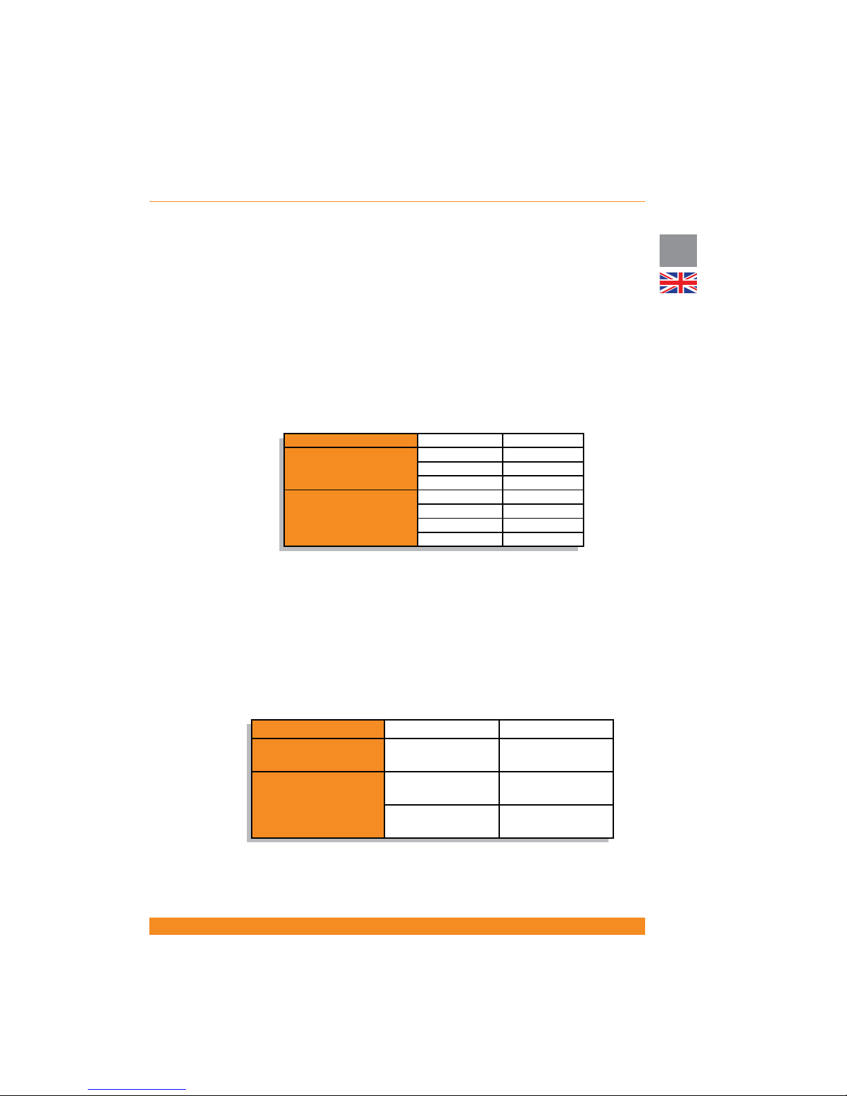
These UPS units are delivered with various nominal powers and in various housings.
The following table provides an overview of the various versions of the unit:
Depending on your local market, these units can include a front panel based on LED indicators or a front
panel with a LCD Display.
For units which include a front panel based on LED indicators as standard, front panels with LCD display are
available as accessory. These front panels have to be ordered separately. Installation of the front panel with
LCD display must be carried out by quali ed technicians. Please contact the responsible customer service
representative. For further details on installation, please see section 6.5.
The following battery packs are available:
Housing Designation
Nominal Power
Tower
(upright unit)
Active 700 T 700 VA
Active 1000 T 1000 VA
Active 1500 T 1500 VA
Rack/Tower convertible
(can be upright or rack-
mounting unit)
Active 1000 RT 1000 VA
Active 1500 RT 1500 VA
Active 2000 RT 2000 VA
Active 3000 RT 3000 VA
Housing Designation Compatible UPS Unit
Tower
(upright unit)
BP-A1000/1500 T
Active 1000 T
Active 1500 T
Rack/Tower convertible
(can be upright or rack-
mounting unit)
BP-A1000/1500 RT
Active 1000 RT
Active 1500 RT
BP-A2000/3000 RT
Active 2000 RT
Active 3000 RT
Page 12

10
UK
Chloride Active
945044.066
2.3 Symbols
ATTENTION: Indicates instructions, which if not observed, may endanger reliability of your UPS or the security
of your data.
WARNING: Indicates instructions, which if not observed, present risk of electric shock, may endanger your
life, your health, reliability of your UPS or the security of your data.
NOTE: Indicates instructions and comments that provide further details on the UPS and complement the
main text.
2.4 Documentation structure
These instructions can be supplemented with additional sheets, which e.g. describe speci c extensions or
options.
Page 13
11
Chloride Active
UK
3 Setup and Installation
3.1 Delivery
This unit has been thoroughly checked before shipment. Upon receipt, check the packaging and ensure that
the contents are undamaged. Any damage must be reported to the shipper and any missing parts must be
reported to the supplier immediately.
3.2 Unpacking
Care should be taken when removing the packaging in order to avoid damaging the unit. Check all packaging
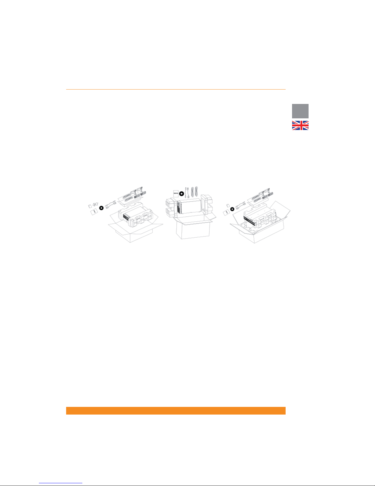
materials to ensure that no items are discarded (please see below gures). Note that they are only descriptive
gures whose content is subject to changes according to local markets.
3.3 Scope of delivery
The following items are included within the packaging:
3.3.1 Tower units (UPS)
- 1 x this user manual
- 1 x UPS unit
- 1 x quickstart guide
- 1 x CD with user software
- 2 x connection cables IEC320 C14 (male) - IEC C13 (female) for the UPS output
- 1 x RS232 interface cable
- 1 x USB cable
3.3.2 Tower units (Battery Packs)
- 1 x Battery Pack unit
- 1 x battery extension cable
- 1 x battery pack detection cable for auto-detection of number of battery packs connected
3.3.3 Rack/Tower units (UPS)
- 1 x this user manual
- 1 x UPS unit
- 1 x quickstart guide
- 1 x CD with user software
- Connection cables as per below:
1 and 1.5kVA rack/tower units
2 and 3kVA rack/tower units
Tower units
Page 14
12
UK
Chloride Active
945044.066
- 1 x RS232 interface cable
- 1 x USB cable
- 2 x front brackets for rack-mounting and required mounting hardware
- 2 x sets of tower feet for oor-mounting
- 2 x sliding rail kits for rack-mounting (optionally) and required mounting hardware
3.3.4 Rack/Tower units (battery packs)
- 1 x Battery Pack unit
- 1 x battery extension cable
- 1 x battery pack detection cable for auto-detection of number of battery packs connected
- 2 x front brackets for rack-mounting and required mounting hardware
- 2 x spacers to be assembled with the sets of tower feet for oor-mounting
- 1 x plate for securing the battery pack to the UPS for oor-mounting
- 2 x sliding rail kits for rack-mounting (optionally) and required mounting hardware
3.4 Storage
If it is not intended that the UPS be used within seven days of delivery, attention shall be paid to the storage
conditions.
The UPS should be stored in a clean, dry environment and away from temperature extremes. It is
recommended that the unit be stored in a temperature controlled, moderate humidity environment. The
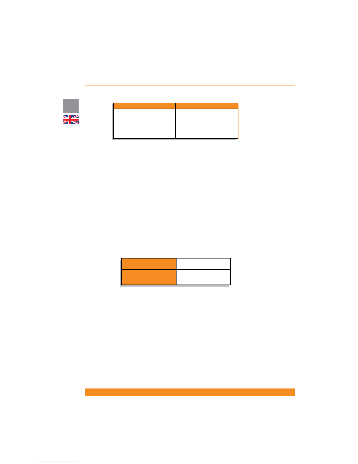
table below provides the temperature and humidity storage limits:
3.5 Handling
The UPS must be kept upright at all times and handled with care. Damage may be caused if dropped or
subjected to severe impact.
3.6 Environmental Conditions
The UPS tower version must be installed vertically. The UPS rack/tower version (RT hereinafter) can be
installed vertically or horizontally, depending on the desired arrangement.
In any case, it must be installed on a level and even surface and in an area protected from extremes of
temperature, water, humidity and the presence of conductive powder or dust (see section 3.10). Do not
stack units and do not place any objects on top of a unit.
The functional temperature range of the UPS is speci ed in section 8 (“Technical Speci cations”).
The ideal ambient temperature range is 15ºC to 25ºC.
Expected battery runtimes and battery life is de ned at 20ºC. Increments of temperature above 25ºC will
reduce the expected battery life.
1000, 1500 and 2000VA models 3000VA models
2 x connection cables IEC320
C14 (male) - IEC C13 (female)
for the UPS output
1 x connection cable Schuko
(male) - IEC320 C19 (female) for
the UPS input
1 x multisocket extension
IEC320 C20 (male) - 3 x Schuko
(female) for the UPS output
Temperature limits
-25ºC/50ºC (w/o batteries)
-15ºC/40ºC (with batteries)
Relative humidity (non-
condensing)
10-90%
Page 15

13
Chloride Active
UK
3.7 Floor Loading
Taking into consideration the weight of the UPS and extension battery packs of Tower models and RT
models operating as Tower, it is necessary that the oor in the chosen location be capable of supporting the
weight of the units.
NOTE: Weights for the UPS and battery packs are shown in section 8 (“Technical Speci cations”).
3.8 Rack Loading
Taking into consideration the weight of the UPS and extension battery packs of RT models that may be
mounted in an associated rack, it is necessary that the chosen cabinet be capable of supporting the weight
of the units.
NOTE: Weights for the UPS and battery packs are shown in section 8 (“Technical Speci cations”).
3.9 Ventilation
It is necessary to leave a minimum space of at least 50 mm in front and rear of the UPS to allow a ow of
air.
Electrical maintenance and servicing requires access to the front and back of the UPS. Provide the
necessary space to allow service personnel access to the UPS.
3.10 Installation Data
3.11 Rack-Mounting the UPS or External Battery Cabinets (RT Models Only)
The Rack/Tower UPS’s and external battery packs can be rack-mounted in four-post frames. The UPS and
external battery packs use identical mounting hardware and the procedure for mounting either is the same.
ATTENTION: The UPS draws cooling air from the front. If the rack has a door on the front, make sure that
there is some clearance between the vents and the rack door.
Because of the weight and dimensions of these units (particularly the 2 and 3kVA models), it is strongly
recommended that two people lift the unit for rack-mounting. If only one person is available, it may be
possible to disconnect and take out the UPS internal batteries, rack-mount the UPS without batteries (less
weight) and re-connect the internal batteries once that the UPS is rack-mounted.
Item Speci cation
Ambient temperature 0ºC to 40ºC
Relative humidity (non condensing) 20%-90%
Environment Controlled (of ce or similar)
Max. altitude (w/o derating) 3.000 meters
Input power connection Rear
Output power connection Rear
Battery power connection Rear
Air inlet Front
Air outlet Rear
Page 16
14
UK
Chloride Active
945044.066
Please use only the supplied fasteners to attach the supplied mounting brackets to the UPS or external
battery packs.
If external battery packs are included in your installation, please mount them rst and as low as possible.
Start with the lowest available position and work up. Your UPS should be installed last and end up on the
top of all the battery units for proper cable routing.
ATTENTION: Use all supplied mounting hardware on each UPS and external battery pack. NEVER depend
on lower devices to support other devices.
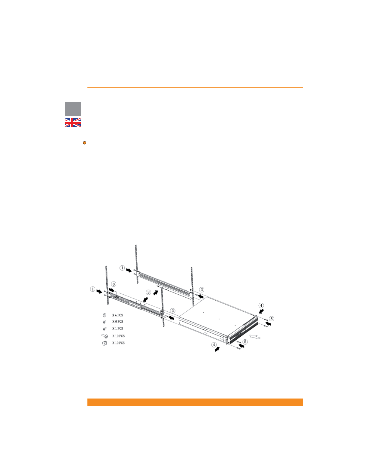
All mounting materials are available (bundled or optionally) to install the UPS into a rack. To prepare the
UPS and external batteries for use in a rack con guration, rst install the sliding rails (optional accessory),
and then install the UPS and batteries following the steps below:
1. Attach rear of rails to rear of rack with two screws provided
2. Attach front of rails to front of rack with one screw provided
3. Assemble side rails and secure each rail together with three screws
4. Attach front brackets to each side of UPS with four screws on each side
5. Slide UPS into position in the rack and secure with two screws on each side of UPS
6. Attach rail to rear side of the UPS ( xing point for safer transportation)
7. Repeat the above steps for each UPS or battery pack to be mounted
After mechanical installation is complete, please read section 4 for proper commissioning and operation of
the system.
Page 17
15
Chloride Active
UK
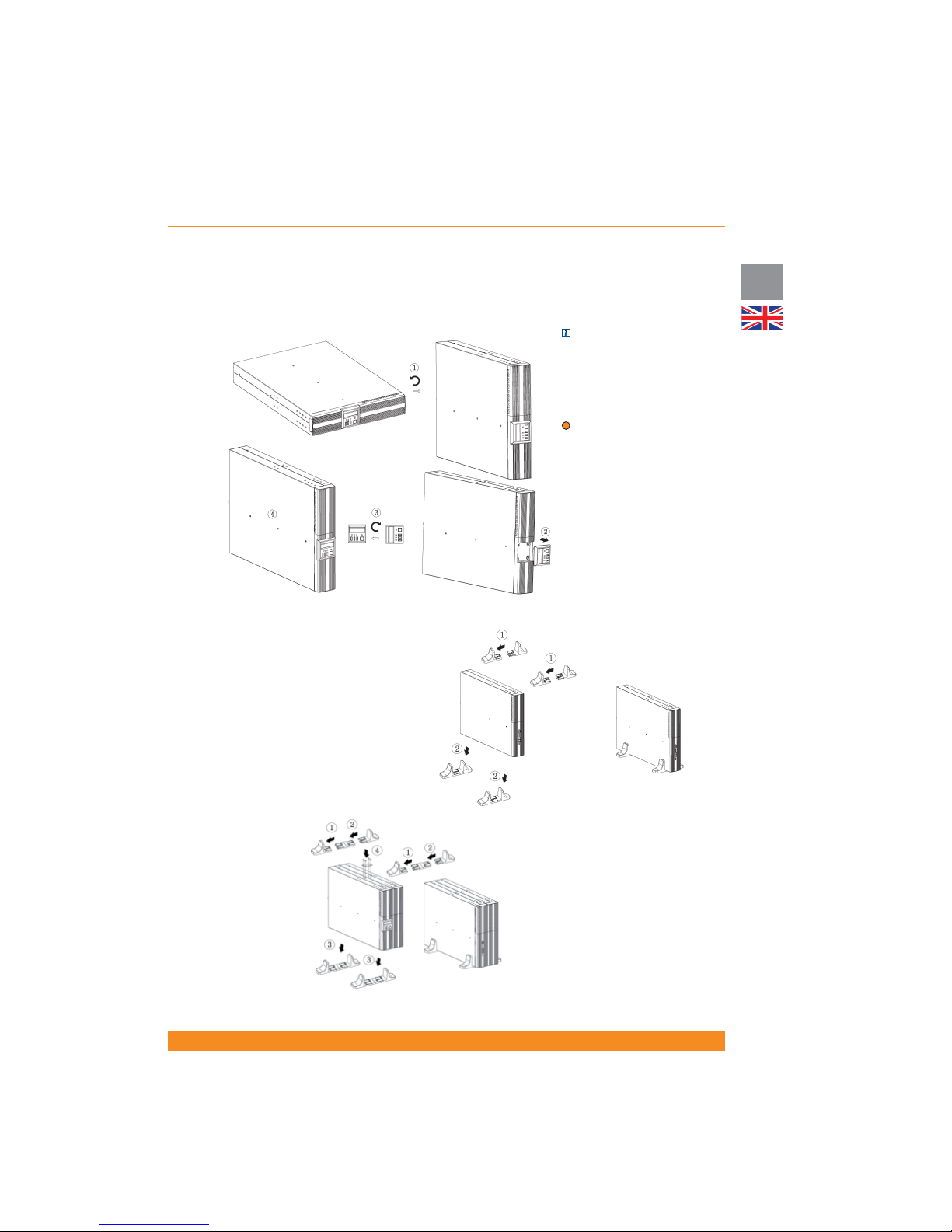
3.12 Floor Mounting the UPS or External Battery Cabinets (RT Models Only)
The RT UPS and external battery packs are designed to be oor standing as an alternative to rack
mounting.
NOTE: (only for units with front
panel with LCD display). The
LCD Display can be rotated to
the adequate position when it is
oor-mounted as illustrated in the
next gure.
ATTENTION: Use all supplied
mounting hardware on each UPS
and external battery
After mechanical installation is
complete, please read section
4 for proper commissioning and
operation of the system.
3.12.1 Mounting the UPS
only
Assemble the two sets of feet
included with the UPS and place
the UPS between feet as shown
in the next gures.
3.12.2 Mounting the UPS
plus One External Battery
Assemble the two sets of feet
with the spacer provided and
place the UPS and battery pack
between feet as shown in the
next gure. Then secure UPS
and battery pack with plates and
screws provided.
Page 18

16
UK
Chloride Active
945044.066
4 Operation and Commissioning
4.1 Theory of Operation
ATTENTION: This UPS is supplied with standard power cords and receptacles suitable for its use in your
area of operation. It may be installed and operated by non-technician personnel.
4.1.1 Line Mode
In use, the UPS is connected between AC input power and the load. The operation of this UPS is based
on the on-line double conversion principle in which the input AC power is rst converted to DC, and
secondarily converted back to a sine wave of a xed frequency and voltage to supply controlled power
to the load. This UPS topology is used to prevent the critical load from suffering a variety of power line
problems, including the total loss of input AC power.
4.1.2 Battery Mode
In the event of a mains failure, the maintenance-free batteries will continue to provide an uninterrupted
supply of energy to the load. In practice, most mains failures are of relatively short duration. Therefore,
the energy stored in the UPS’s batteries is, in most cases, suf cient to ensure continuous operation of the
connected systems until the mains power is re-established. In the event of a long lasting mains failure, the
UPS can be utilized with shutdown software to enable a controlled shutdown of connected systems.
The most reliable method for determining the estimated battery runtime is the use of the LCD Display or the
application of the user software or SNMP network card. With this software, the estimated remaining battery
capacity is indicated before and during an AC power failure. These products also allow for automated
shutdown procedures that can shut down the attached devices after safely closing open applications
programs and the operating system. After return of the mains voltage, the UPS automatically restores
power to the connected equipment and starts recharging the batteries.
4.1.3 Bypass Mode
If the UPS is in bypass mode, the load is supplied directly from the AC mains via the internal automatic
bypass.
The unit automatically starts up in bypass when it is connected to the AC mains, supplying voltage
immediately to the load. It is necessary to press the Inverter ON button to start the inverter and switch the
unit to line mode (normal operation).
In the event of an overload on the UPS or internal UPS failure, the load is immediately supplied directly
from the mains via this automatic internal bypass. As soon as normal status is re-established, an automatic
switch over to inverter operation is performed.
Alternatively, the unit can be forced to bypass by the user using the front panel buttons or LCD Display.
In this case, if the input parameters (voltage, frequency) go out of tolerances, the unit automatically shuts
down.
4.1.4 ECO Mode
When the ECO Mode is enabled and mains conditions are within tolerances, the output is fed directly from
the input via the internal bypass, thus achieving very high ef ciency values and therefore saving energy.
When ECO mode is activated and mains conditions go out of tolerances, the unit automatically feeds the
load through the inverter to keep the load protected.
When the unit is operating on ECO mode, the internal battery charger is working. Therefore, batteries are
kept charged.
For details on how to enable/disable this mode, please refer to 4.4.5.
4.1.5 Frequency Converter Mode
The UPS can operate as a frequency converter, providing 50Hz or 60Hz (whichever is selected) to the
output when the input frequency is within the 40-70Hz range.
Page 19
17
Chloride Active
UK
When the unit is operating in this mode, there is a 50% power de-rating. This means that only 50% of the
UPS nominal power can be used when operating in this mode.
If the unit is operating as a Frequency Converter, neither can ECO Mode be activated nor can the unit be
forced to Bypass Mode.
For details on how to enable/disable this mode, please refer to 4.4.6.
4.1.6 Other Operating Details
This section covers other functionalities featured by the unit. For operating details on them, please see
sections 4.2, 4.3 and 4.4.
a) Green Power Function: when the unit is on battery mode and there is no output load, the unit
automatically shuts down after ve minutes for battery and energy saving.
b) Cold Start: when this functionality is enabled, the unit has the capability to start up when mains power is
not present, thus powering the load directly from the batteries.
ATTENTION: When the UPS is started for the rst time, AC power must be present
c) Auto-Restart: when this functionality is enabled, the unit automatically starts up after autonomy time has
nished upon mains power comeback. Otherwise, it is necessary to start up the unit manually.
NOTE: assuming that this functionality is activated, if there is a mains failure just after the unit has
automatically started up, autonomy time will be short as the batteries have not been fully charged.
d) Site Wiring Fault detection: the unit can detect if input line and input neutral have been inverted and
report a fault in that case.
e) Battery test: the UPS can perform a battery test in two different ways: manually, upon user request, or
automatically, with a xed interval between tests.
f) Controllable outlets: this UPS includes two groups of output controllable sockets (outlet 1 and outlet 2).
Each group can be con gured to automatically shut down when the remaining battery capacity goes below
a certain value (75%, 50%, 25% or 0%) or upon user request.
ATTENTION: It is suggested that the highest priority equipment be attached to the main outlets and that
lower priority loads be attached to the controllable outlets.
g) Remote On Off (ROO) / Remote Power Off (RPO): the unit has terminals on the rear side that allow the
user to remotely shut down and start up the unit (ROO) or remotely shut down the unit without the option of
re-starting it remotely (RPO). For operating details, please see section 4.4.8.
h) Compatibility with gensets: this UPS can operate with most of the gensets available in the market.
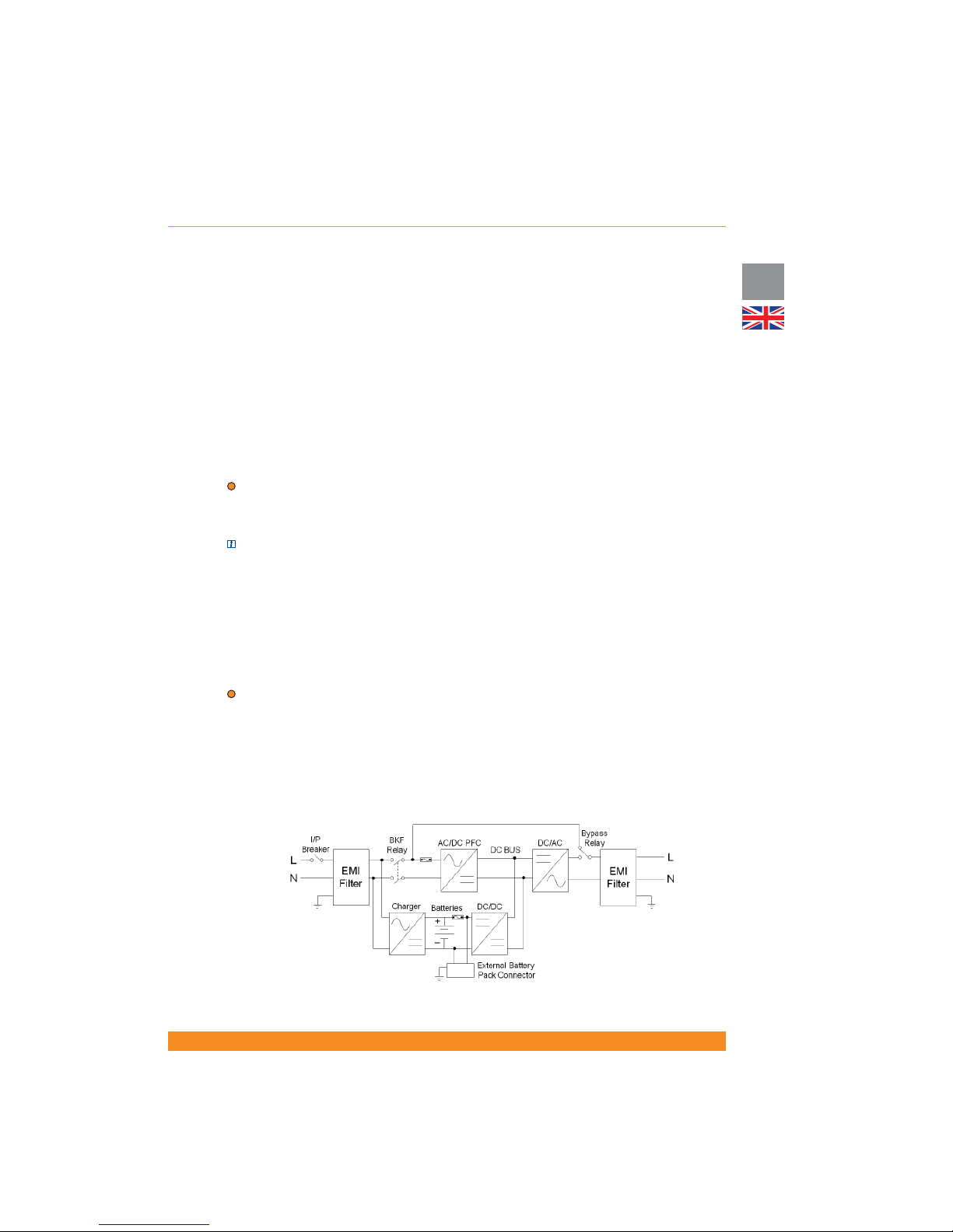
4.1.7 Block Diagram
Page 20
18
UK
Chloride Active
945044.066
4.2 Front Panel Indicators and Operating Elements Description
4.2.1 Units with LED indicators
Depending on your local market, the UPS can be equipped with a front panel containing a series of
switches and indicator LED’s that provide the operator with the current status of the UPS and the ability to
change UPS operational mode.
NOTE: for units with front panels with LED indicators, front panels with LCD display are available as an
accessory and have to be ordered separately. For operation details about them please refer to section 4.2.2
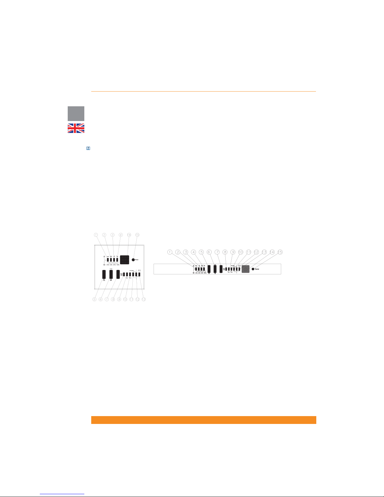
4.2.1.1 Description of the elements
The front panel contains a series of switches and indicator LEDs that provide the operator with the current
status of the UPS and the ability to change UPS operational mode:
- Inverter ON/OFF switch and LED
- A simpli ed block diagram of the UPS shows the current operational mode of the UPS (i.e. line mode,
battery mode, bypass mode)
- Two LED indicators show the current status (ON or OFF) of the controllable outlets 1 and 2.
- Four additional LEDs provide error status, UPS load percentage or battery charge percentage depending
on the associated front panel button status.
- Site Wiring Fault detection switch and LED
9. Outlet 1 ON/OFF LED
10. Outlet 2 ON/OFF LED
11. Bypass Mode LED
12. Line Mode LED
13. Battery Mode LED
14. Inverter ON/OFF Button
15. Inverter ON LED
1. Site Wiring Fault Detection LED
2. Battery Fault LED
3. UPS Fault LED
4. UPS Overload LED
5. Display Selection Button
6. LED Test/Alarm Reset Button
7. Site Wiring Fault E/D Button
8. Site Wiring Fault E/D LED
Page 21

19
Chloride Active
UK
4.2.1.2 Operation
The following chart describes functions and operations of these buttons and LEDs
(*) These LEDs show battery capacity level or output load level (depending on button 5) and normally they should be read
as a group. However, in case of certain events (SWF, Battery Fault, UPS Fault or UPS Overload), they pass to indicate it by
ashing and should be read individually.
Button/LED Function Operation/De nition
Button 14 Inverter ON/OFF Button
Press one second to switch on/off the inverter
Button 7 Site Wiring Fault E/D Button
Press seven seconds to enable/disable Site
Wiring Fault detection
Button 6
Mute Buzzer (Alarm Reset) Press one second to mute the buzzer
LED test Press for LED test (all LEDs ashing)
Force the unit to bypass or
comeback
Press buttons 6 and 5 for four seconds to force
the unit to bypass or to return from bypass
Reset LCM Alarm (alarm which
indicates end of estimated
battery life)
Press buttons 6 and 5 for three seconds to
reset this alarm (if the alarm is active, it is
necessary to push these buttons 4 more
seconds to switch the unit to bypass, as per
above functionality)
Button 5
Show Output Load level
Press to show output load level on LEDs 1, 2
3 and 4 (by default they show battery capacity
level)
Cold Start Enable/Disable
Press ve seconds to enable/disable cold start
functionality
LED 1 (*) Site Wiring Fault Detection LED
Indicates if Site Wiring Fault has been detected
LED 2 (*) Battery Fault LED
Indicates if a battery fault has been detected
LED 3 (*)
UPS Fault LED
Indicates if a UPS fault has been detected
LED 4 (*) UPS Overload LED
Indicates if an output overload has been
detected
LEDs 1, 2, 3
& 4 (*)
Battery Capacity Level / Output
Load Level
Indicates battery capacity level (by default), or
output load level if button 5 is pressed
LED 8
Site Wiring Fault E/D LED Indicates if Site Wiring Fault detection is enabled
or disabled (enabled: ON; disabled: OFF)
LED 9
Outlet 1 ON/OFF LED
Indicates if group 1 of the output controllable
sockets is supplying power or not (supplying
power: ON; not supplying power: OFF; status
change in progress: ashing)
LED 10
Outlet 2 ON/OFF LED
Indicates if group 2 of the output controllable
sockets is supplying power or not (supplying
power: ON; not supplying power: OFF; status
change in progress: ashing)
LED 11 Bypass Mode LED Indicates if the unit is on bypass mode ( ashing)
LED 12 Line Mode LED Indicates if the unit is on line mode (ON)
LED 13 Battery Mode LED Indicates if the unit is on battery mode (ON)
LED 15 Inverter ON LED Indicates if the inverter is ON or OFF
Page 22
20
UK
Chloride Active
945044.066
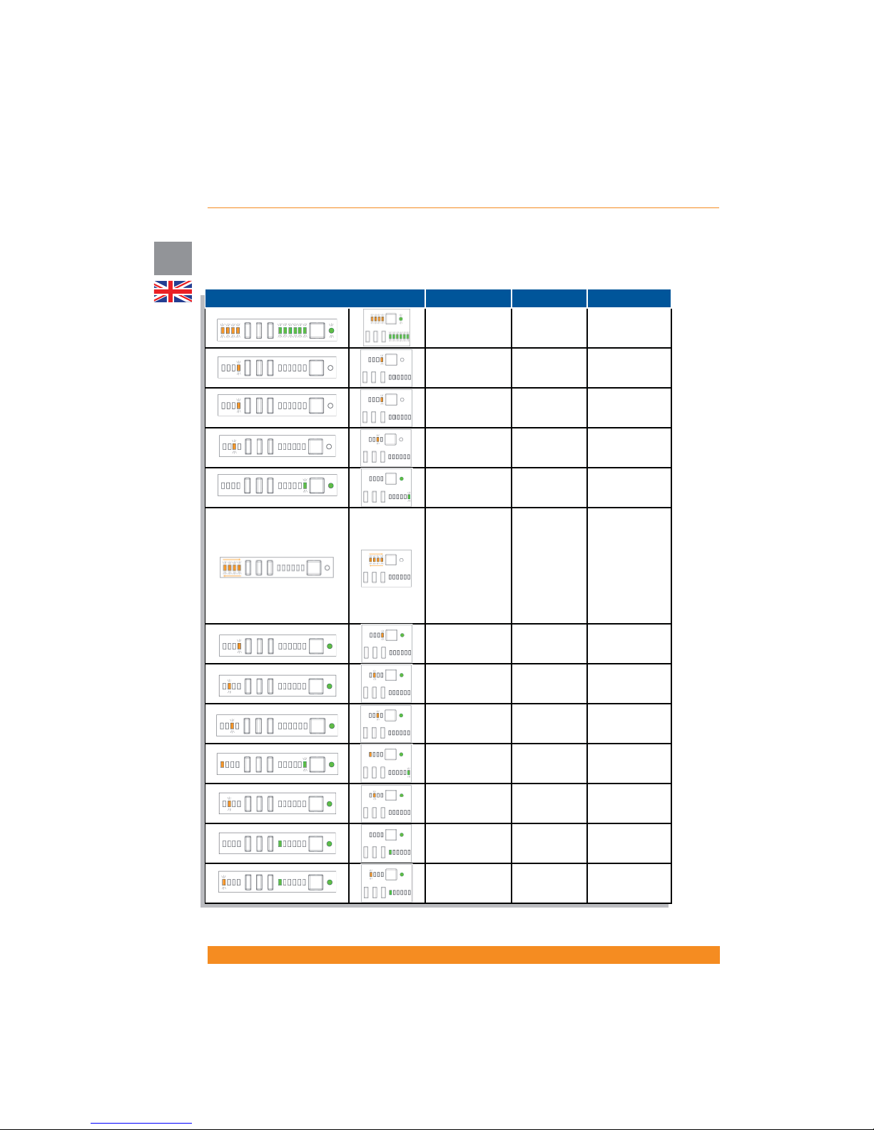
4.2.1.3 Indicators
The following chart describes visual and acoustic indications when certain conditions happen. For visual
indications, only the representative LEDs are shown (the others may be ON or OFF, depending on other
operative conditions).
LED display Indicators Acoustic UPS Condition
All LEDs ashing
three times
Three beeps
Start-up
sequence
LED 4 ashing.
LEDs 1, 2 & 3 off
Continuous
beep
Overload fault
LED 4 ashing.
LEDs 1, 2 & 3 off
Continuous
beep
Inverter
shortcircuit fault
LED 3 ashing.
LEDs 1, 2 & 4 off
Depending on
fault
Other UPS fault
LED 13 ashing
three times
Three beeps
Line Mode to
Battery Mode
LED 4 ON
LED 3 ON
LED 2 ON
LED 1 ON
LED 1 OFF
LED 2 OFF
LED 3 OFF
LED 4 OFF
LED 4 ON
Continuous
beep
Remote Power
Off warning
LED 4 ashing.
LEDs 1, 2 & 3 off
One beep per
second
Overload
warning
LED 2 ashing.
LEDs 1, 3 & 4 off
One beep per
second
Battery
disconnected or
battery test fault
LED 3 ashing.
LEDs 1, 2 & 4 off
One beep per
second
Charger fault
LED 1 ON, LED
13 ashing
One beep
every three
seconds
Battery Low
LED 2 ashing.
LEDs 1, 3 & 4 off
One beep
every 30
minutes
LCM Alarm (end
of battery life)
LED 8 ON
-
Site Wiring
Fault detection
enabled
LED 1 ashing,
LEDs 2, 3 & 4
OFF. LED 8 ON
Continuous
beep
Site Wiring Fault
Detected
Page 23
21
Chloride Active
UK
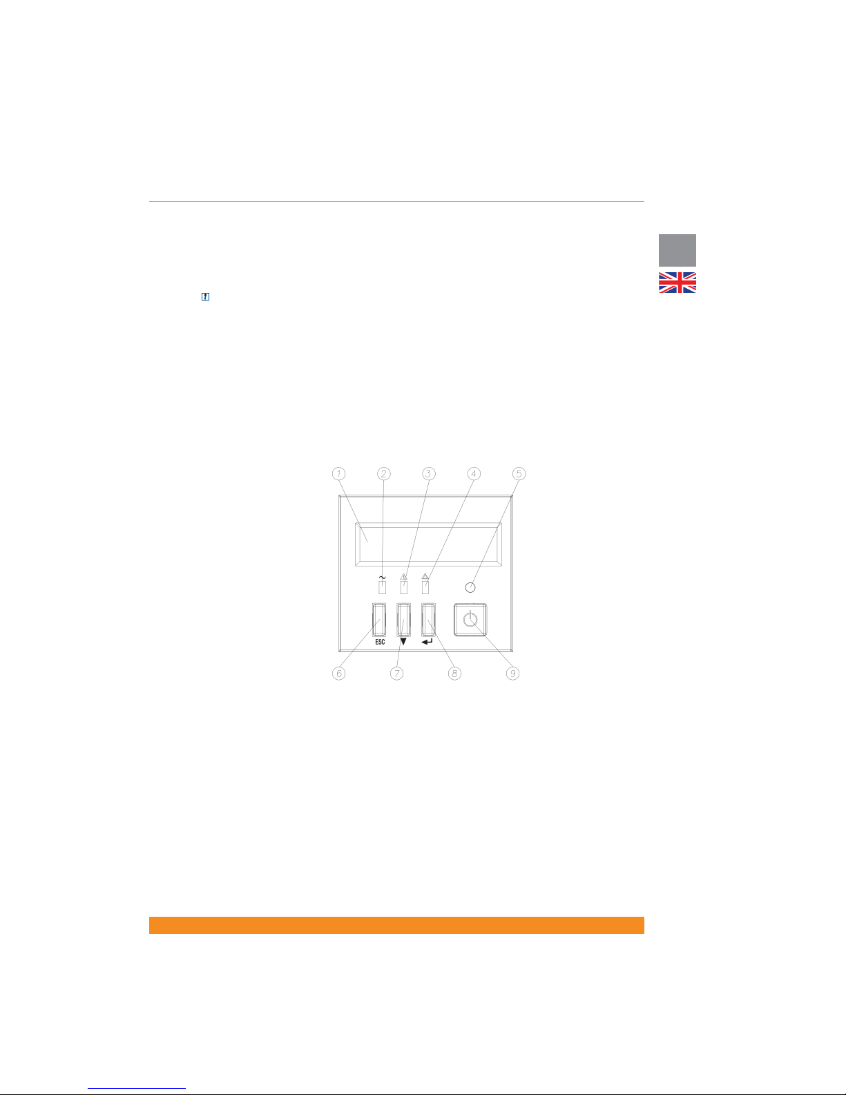
4.2.2 Units with LCD Display
Depending on your local market, the UPS can be equipped with a front panel with a LCD Display instead of
LED indicators.
NOTE: for units with front panels with LED indicators, front panels with LCD display are available as an
accessory and have to be ordered separately
1. Display
2. Mains LED (green): illuminates if mains input power is within tolerances
3. Bypass Mode/ECO Mode LED (orange): illuminates if the unit is in bypass (forced, due to ECO mode…)
4. Fault LED (red): illuminates if the unit is reporting a fault: battery fault, inverter fault, BUS fault…
5. Inverter ON LED (green): illuminates if the inverter is ON
6. ESC Button (goes up one level on the menu hierarchy). Note: press this button for three seconds to reset
the LCM alarm (alarm which indicates end of estimated battery life).
7. Scroll-Down Button (scrolls down through menus and submenus)
8. ENTER Button (goes down one level on the menu hierarchy or selects the displayed option)
9. Inverter ON/OFF Button (Switches on/off the inverter)
Page 24
22
UK
Chloride Active
945044.066
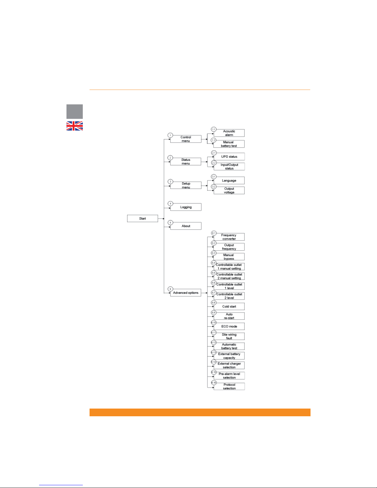
4.2.2.1 Menus and Functionalities
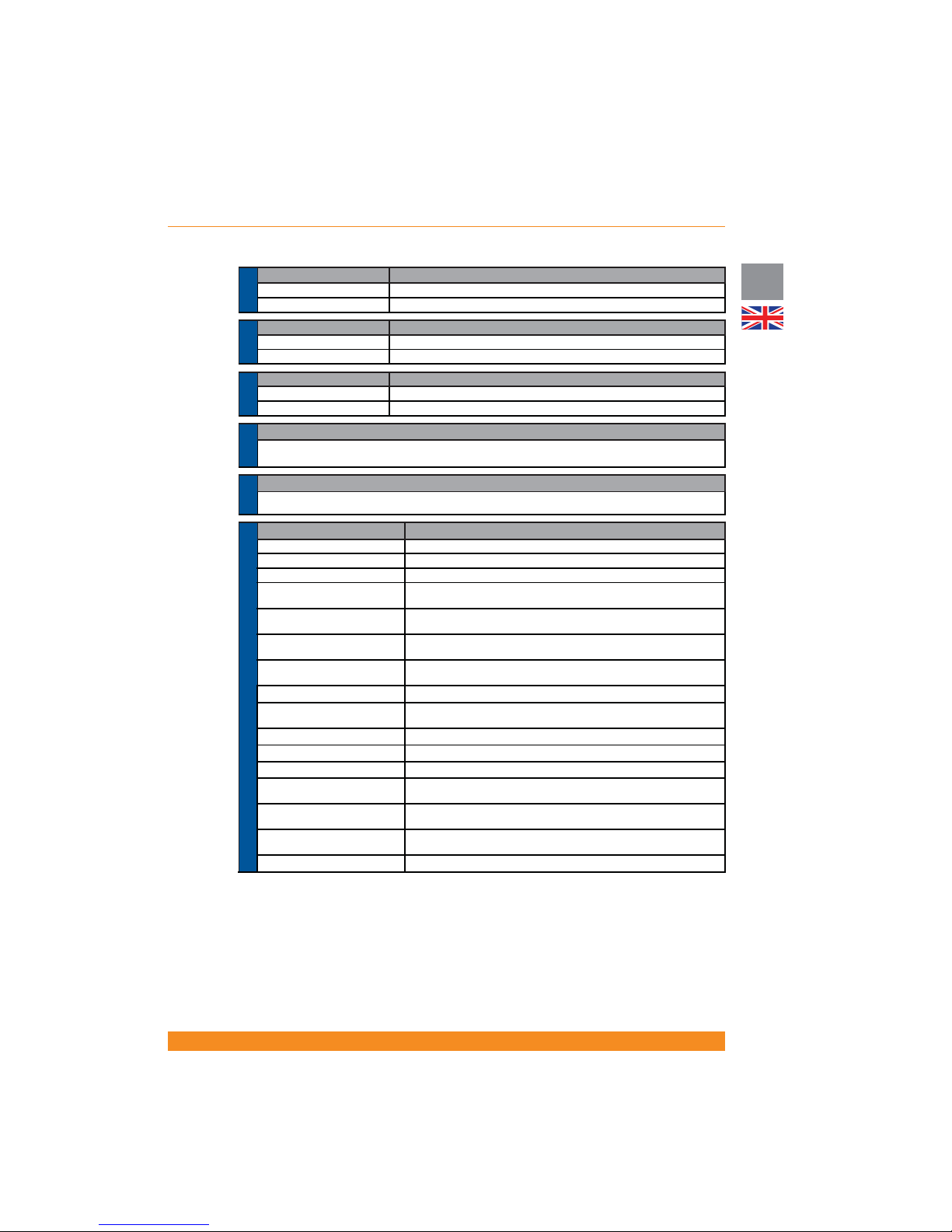
Functions available in the menus and sub-menus are explained below.
Page 25
23
Chloride Active
UK
Submenu Functionality
1.1 Acoustic Alarm Activation or deactivation of acoustic alarm (buzzer)
1.2 Manual Battery Test Performs a battery test when this option is selected
MENU 1.-
CONTROL
Submenu Functionality
2.1 UPS Status Displays global UPS Status (operation mode, faults, warnings…)
2.2 Input/Output Status Displays input and output values (voltage, frequency, load…)
MENU 2.-
STATUS
Submenu Functionality
3.1 Language Language selection (English, Spanish, Italian, French, Portuguese, German)
3.2 Output Voltage Selects nominal output voltage (200V, 208V, 220V, 230V or 240V)
MENU 3.-
SETUP
Functionality
Displays the last ve events (faults, warnings…) stored by the UPS and the runtime when they happened. These
stored events are explained in section 4.2.2.2
MENU 4.-
LOGGING
Functionality
Displays power rating, serial number of the UPS, rmware version and current unit runtime
MENU 5.-
ABOUT
Submenu Functionality
6.1 Frequency Converter Enables or disables this operation mode (please check 4.1.5 and 4.4.6 for more details)
6.2 Output Frequency Selects nominal output frequency: 50Hz or 60Hz (only frequency converter mode)
6.3 Manual Bypass Forces the UPS to bypass mode and vice-versa
6.4 Controllable Outlet 1 Manual
Setting
Switches on/off outlet 1 (1st group of output controllable sockets)
6.5 Controllable Outlet 2 Manual
Setting
Switches on/off outlet 2 (2nd group of output controllable sockets)
6.6 Controllable Outlet 1 Level
Selects remaining battery capacity level (75%, 50%, 25% or 0%) below which
outlet 1 (1st group of output controllable sockets) automatically switches off
6.7 Controllable Outlet 2 Level
Selects remaining battery capacity level (75%, 50%, 25% or 0%) below which
outlet 2 (2nd group of output controllable sockets) automatically switches off
6.8 Cold Start Enables/disables this functionality (start-up without mains power)
6.9 Auto Re-Start
Enables/disables this functionality (automatic start-up after autonomy time has
nished and upon mains power comeback)
6.10 ECO Mode Enables or disables this operation mode (please check 4.1.4 and 4.4.5 for more details)
6.11 Site Wiring Fault
Enables/disables this functionality (detection of input phase-neutral inversion)
6.12 Automatic Battery Test Sets automatic battery test interval (daily, weekly, monthly…)
6.13 External Battery Capacity
Selects external battery capacity (Ah) for special / customized con gurations,
in steps of 9Ah up to 250Ah (value selected pressing scroll-down button)
6.14 External Charger Selection
Selects the number of external battery chargers (available as accessory for
special / customized con gurations) connected, from 1 to 3
6.15 Pre-alarm Level Selection
Selects the remaining battery capacity level (75%, 50%, 25% or 0%) below
which the “Battery Low” signal is activated
6.16 Protocol selection Communication protocol selection for particular advanced applications
MENU 6.- ADVANCED OPTIONS
Menu 6 includes options for advanced user and, consequently, access to this menu is protected with a password
(a certain combination of keys).
When this menu is selected, you will be asked to press the code keys (PRESS CODE KEYS (CHECK U.
MANUAL)). Correct code keys combination is:
Press ESC button and release it - press scroll-down button and release it - press ENTER button and release it.
If this sequence and combination of keys is followed, access to the menu will be granted and the display will
show ACCESS GRANTED ATTENTION! If not, an error message will show (ACCESS DENIED WRONG
CODE KEYS).
Page 26
24
UK
Chloride Active
945044.066
4.2.2.2 Warning and fault indicators
The LCD Display shows the last ve events stored and the runtime when they happened (menu 4). They
are listed from 1 to 5, being 1 the newest event and 5 the oldest event. Event 1 is the rst one to be
displayed and events from 2 to 5 are displayed sequentially by pressing the Scroll-Down button.
4.3 Rear Side
4.3.1 Tower units
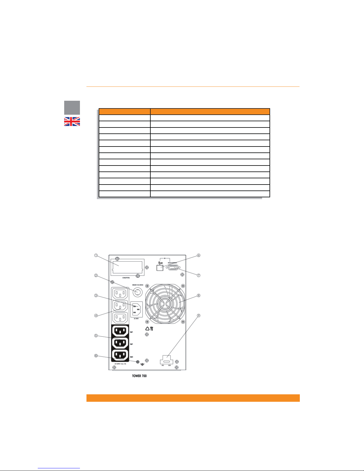
Active 700 T:
Display Message Description
RPO ACTIVE
UPS stopped because RPO (Remote Power Off) has been activated
BATTERY FAULT
Battery failure has been detected. Please check batteries.
INVERTER OVERLOAD
Overload detected on the inverter (line mode or battery mode)
BYPASS OVERLOAD
Overload detected when the unit is on bypass mode
FAN FAULT
Fan failure has been detected
CHARGER OVERVOLTAGE
Charger is delivering overvoltage (internal failure)
DC BUS OVERVOLTAGE
DC voltage on the DC bus too high (internal failure)
DC BUS UNDERVOLTAGE
DC voltage on the DC bus too low (internal failure)
DC BUS UNBALANCE
DC voltage on the DC bus unbalanced (internal failure)
INVERTER OVERVOLTAGE
Inverter is delivering overvoltage (internal failure)
INVERTER UNDERVOLTAGE
Inverter is delivering undervoltage (internal failure)
INVERTER SHORT
Short-circuit on the inverter (internal failure)
SITE WIR. FAULT
Site wiring fault detected. Please check input wiring arrangement.
1. SNMP Slot
2. Input circuit breaker
3. Input power connection
4. Not controllable output sockets
5. Controllable outlets (2 groups)
6. USB port
7. RS232 port
8. Fan
9. ROO/RPO terminals
10. Earth screw
Page 27
25
Chloride Active
UK
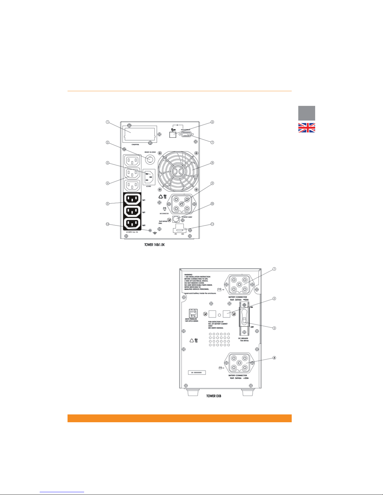
1. SNMP Slot
2. Input circuit breaker
3. Input power connection
4. Not controllable output sockets
5. Controllable outlets (2 groups)
6. USB port
7. RS232 port
8. Fan
9. External battery pack connector
10. RJ11 port for battery pack
detection cable
11. ROO/RPO terminals
12. Earth screw
Active 1000 T and Active 1500 T:
1. Battery pack connector
2. RJ11 port for battery pack
detection cable
3. Circuit breaker
4. Battery pack connector
BP-A1000/1500-T:
Page 28
26
UK
Chloride Active
945044.066
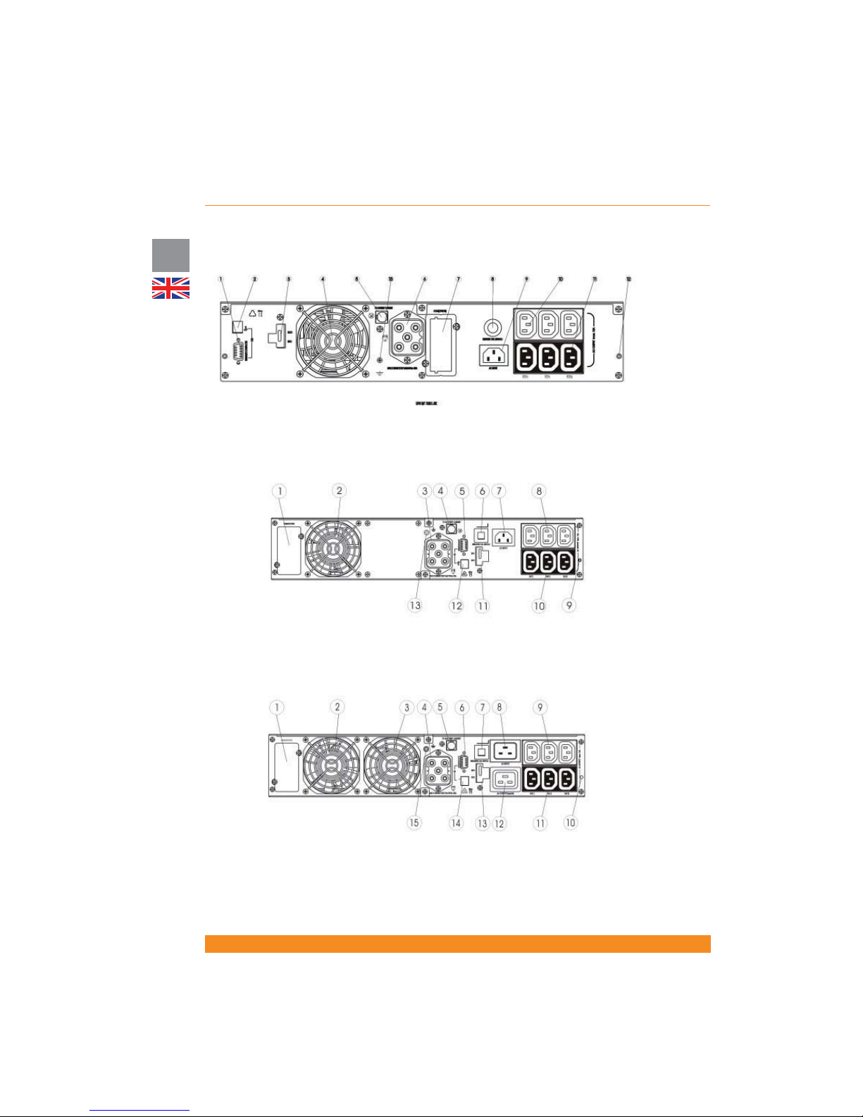
1. RS232 port
2. USB port
3. ROO/RPO terminals
4. Fan
5. RJ11 port for battery pack detection
cable
6. External battery pack connector
7. SNMP slot
8. Input circuit breaker
9. Input power socket
10. Not controllable output sockets
11. Controllable outlets (2 groups)
12. Fixing point for sliding rail
13. Earth screw
4.3.2 Rack/Tower units
Active 1000 RT and Active 1500 RT:
Active 2000 RT:
1. SNMP slot
2. Fan
3. External battery pack connector
4. RJ11 port for battery pack detection
cable
5. RS232 port
6. Input circuit breaker
7. Input power socket
8. Not controllable output sockets
9. Fixing point for sliding rail
10. Controllable outlets (2 groups)
11. ROO/RPO terminals
12. USB port
13. Earth screw
Active 3000 RT:
1. SNMP slot
2. Fan
3. Fan
4. External battery pack connector
5. RJ11 port for battery pack detection
cable
6. RS232 port
7. Input circuit breaker
8. Input power socket
9. 10Amps not controllable output
sockets
10. Fixing point for sliding rail
11. 10Amps controllable outlets (2
groups)
12. 16Amps output socket
13. ROO/RPO terminals
14. USB port
15. Earth screw
Page 29
27
Chloride Active
UK
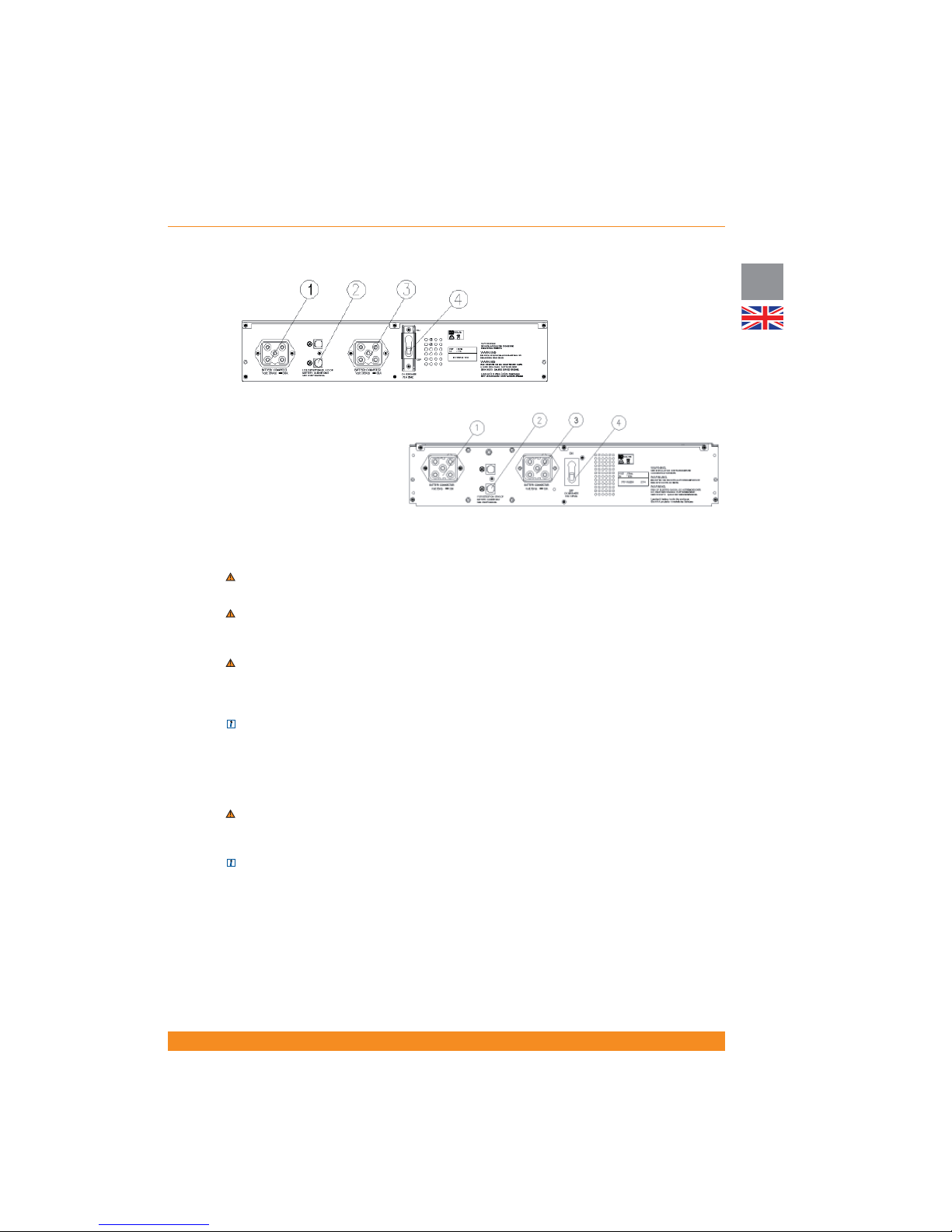
BP-A1000/1500-RT:
1. Battery pack connector
2. RJ11 port for battery pack detection
cable
3. Battery pack connector
4. Circuit breaker
BP-A2000/3000-RT
1. Battery pack connector
2. RJ11 port for battery pack detection
cable
3. Battery pack connector
4. Circuit breaker
4.4 Commissioning and Shutdown
4.4.1 Electrical preparations
WARNING: Before connecting any input wiring to the UPS, take precautions to ensure that all circuits being
used are the proper voltage and current required for the UPS.
WARNING: as soon as the UPS is connected to the AC mains supply, voltage is available at the output
sockets (via internal bypass), even if the inverter ON button has not been pressed. When this button is
pressed, the inverter is switched on and the UPS starts working in line mode.
WARNING: Electrical shock hazard: even when the UPS is disconnected from the mains, hazardous
voltages may still exist at the output receptacles of the UPS. The UPS receives power from more than
one source – AC input and DC input from batteries. All input sources (AC and DC) must, therefore, be
disconnected before carrying out maintenance work inside the UPS.
NOTE: Under EMC regulations, output cables can not be longer than 10 meters, communication cables can
not be longer than 3 meters and battery extension cables can not be longer than 3 meters.
4.4.2 Connections
4.4.2.1 External battery packs connections
WARNING: Before connecting a battery pack to the UPS, the circuit breaker of the battery pack must be
switched to “OFF”. After electrical connection with the UPS is established, the breaker must be switched to
“ON”.
NOTE: Each battery pack contains two battery connectors. The rst battery pack is connected to the UPS
using the cable supplied with the pack. Each additional extension battery pack is connected by attaching its
cable to the previous pack.
If external battery packs are to be used, they should be connected prior to connection the UPS to the input
power. To connect external battery cabinets, follow the steps below:
1. Set the circuit breaker on each battery cabinet to the “OFF” position
2. Connect a battery extension cable between the battery receptacle on the rear of the UPS and one
battery receptacle on the rear of the rst battery pack
3. Connect a battery extension cable between one battery receptacle on the rear of the rst battery pack
Page 30

28
UK
Chloride Active
945044.066
and one battery receptacle on the rear of the second battery pack
4. Continue “daisy-chaining” the battery packs until all are connected.
5. Connect a battery pack detection cable between the RJ11 port on the rear side of the UPS and a RJ11
port on the rear side of the rst battery pack
6. Connect a battery pack detection cable between one RJ11 port on the rear of the rst battery pack and
one RJ11 port on the rear of the second battery pack
7. Continue “daisy-chaining” the battery packs with the battery pack detection cables
8. Set the circuit breakers on each battery cabinet to “ON” position
NOTE: The maximum quantity of external battery packs that can be connected to the UPS is four.
NOTE: for special or customized external battery con gurations, it is possible to select the external battery
capacity via LCD Display
4.4.2.2 Power Connections
After all external batteries are connected, make the necessary input and output power connections by
following the steps below.
1. Connect the input power cord to the AC inlet
NOTE: The batteries will immediately begin charging upon availability of the input power.
WARNING: as soon as the UPS is connected to the AC mains supply, voltage is available at the output
sockets (via internal bypass), even if the inverter ON button has not been pressed
2. Connect the load to the UPS. It is suggested that the highest priority equipment be attached to the main
outlets and that lower priority loads be attached to the controllable outlets.
NOTE: With the LCD Display front panel or user software, the controllable outlets can be set to have a
pre-scheduled shutdown during battery operation in order to conserve battery power for the highest priority
loads.
3. After all connections are made, follow the instructions in the next section (“Start-up Procedure”) to start
your UPS and external battery packs
4.4.3 Start-up Procedure
ATTENTION: This UPS is supplied with standard power cords and receptacles suitable for its use in your
area of operation. It may be installed and operated by non-technician personnel.
4.4.3.1 Initial UPS Start-up Procedure
ATTENTION: When the UPS is started for the rst time, AC power must be present
Units with LED indicators Units with LCD display
When using the UPS for the rst time, con rm AC power
is present. Following 4.4.2.2, power should be available
to the connected equipment via internal bypass once the
input has been connected to the AC mains.
Press the inverter ON/OFF button to switch on the
inverter and switch the UPS to line mode. The UPS
will respond with some beeps and illuminations of LED
indicators, and turn on the Line Mode LED and Inverter
ON LED indicating that the unit is now in line mode.
Protected power should now be available to the
connected equipment via the inverter.
When using the UPS for the rst time, con rm AC power
is present. Following 4.4.2.2, power should be available
to the connected equipment via internal bypass once the
input has been connected to the AC mains.
Press the inverter ON/OFF button to switch on the
inverter and switch the UPS to line mode. The UPS will
respond with some beeps and then turn on the Mains
LED and the inverter ON LED indicating that the unit
is now in line mode. The LCD Display will show the
message LOAD PROTECTED and will indicate the
output power.
Protected power should now be available to the
connected equipment via the inverter.
Page 31

29
Chloride Active
UK
4.4.3.2 Normal Start-up Procedure
Units with LED indicators Units with LCD display
Following 4.4.2.2, power should be available to the
connected equipment via internal bypass once the
input has been connected to the AC mains (if AC mains
power is available).
Press the inverter ON/OFF button to switch on the
inverter; or press twice if AC power is not present and
cold start is enabled to start up in battery mode.
The UPS will respond with some beeps and illuminations
of LED indicators.
If AC power is present, the UPS will turn on the Line
Mode LED and inverter ON LED indicating that the unit
is now in line mode.
If AC power is not present and cold start function is
enabled, the UPS will turn on the Battery Mode LED
and inverter ON LED indicating that the unit is now
providing output power from the battery.
ATTENTION: If the overload indicator is on, or the
“LOAD” indicator is beyond 100%, there are too many
devices connected to the UPS. If only one device is
connected to the UPS and the overload indicator is
on, then the load’s power demand exceeds the rating
of the UPS, and a UPS with a higher power rating
must be used.
NOTE: If the UPS does not respond as above, please
see section 7 (“Troubleshooting”).
Following 4.4.2.2, power should be available to the
connected equipment via internal bypass once the
input has been connected to the AC mains (if AC mains
power is available).
Press the inverter ON/OFF button to switch on the
inverter; or press twice if AC power is not present and
cold start is enabled to start up in battery mode.
The UPS will respond with some beeps and illuminations
of LED indicators.
If AC power is present, the UPS will turn on the Mains
LED and inverter ON LED indicating that the unit is
now in line mode. The LCD Display will show the
message LOAD PROTECTED and will indicate the
output power.
If AC power is not present and cold start function is
enabled, the UPS will turn on the Inverter ON LED
(but not the Mains LED) indicating that the unit is now
providing output power from the battery. The LCD Display
will show the message MAINS FAILURE and will indicate
the estimated remaining back-up time.
ATTENTION: If the display shows a message indicating
OVERLOAD, there are too many devices connected to
the UPS. If only one device is connected to the UPS and
the display shows a message indicating OVERLOAD,
then the load’s power demand exceeds the rating of
the UPS, and a UPS with a higher power rating must
be used
NOTE: If the UPS does not respond as above, please
see section 7 (“Troubleshooting”).
4.4.4 Forced Bypass Procedure
Units with LED indicators Units with LCD display
To place the UPS into bypass mode, press and hold
buttons 5 and 6 for four seconds (see gures on section
4.2.1). The UPS will switch to bypass mode and the
Bypass Mode LED will illuminate. Follow the same
procedure to make the UPS return to line mode.
For other details regarding bypass mode operation,
please see section 4.1.3.
To place the UPS into bypass mode, go to Menu 6
(Advanced Options) and then to submenu “Manual
Bypass” and select TURN UPS TO BYPASS. Follow the
same procedure to make the UPS return to line mode,
selecting TURN UPS TO ONLINE in the same menu.
For other details regarding bypass mode operation,
please see section 4.1.3.
4.4.5 ECO Mode Activation/Deactivation Procedure
NOTE: this functionality cannot be enabled / disabled using front panel buttons in units with front panel
based on LED indicators
In order to enable ECO mode, follow this procedure: with the unit operating in line mode, go to Menu 6
(Advanced options) and then to submenu “ECO Mode” and select ECO MODE ENABLE. The unit will start
to operate in this mode immediately.
To return the unit to line mode, follow the same procedure, now selecting ECO MODE DISABLE.
For other details regarding ECO mode operation, please see section 4.1.4
Page 32
30
UK
Chloride Active
945044.066
ROO RPO
4.4.6 Frequency Converter Mode Procedure
NOTE: this functionality cannot be enabled / disabled using front panel buttons in units with front panel
based on LED indicators
When the unit is in frequency converter mode, it is possible to select with the LCD Display the output
frequency (50Hz or 60Hz) when the input frequency is in the 40-70Hz range. If the AC input is not within
tolerances, the output frequency is 50Hz or 60Hz (whichever is selected) in battery mode.
In order to activate the frequency converter mode, follow this procedure: with the unit operating in line
mode, press the inverter ON/OFF button to switch off the inverter and then disconnect the UPS from
AC mains input. Before the UPS shuts down, go to Menu 6 (Advanced options) and then to submenu
“Frequency Converter” and select ENTER FREQ. CONVERTER MODE. After that, go to submenu “Output
Frequency” and select 50Hz or 60Hz. When you re-start the UPS, it will start up in frequency converter with
the selected output frequency.
To deactivate this mode follow this procedure: press the inverter ON/OFF button and then go to Menu 6
(Advanced options) and then to submenu “Frequency Converter” and select EXIT FREQ. CONVERTER
MODE. Later, press the inverter ON/OFF button to re-start the unit and it will start up normally.
ATTENTION: when the unit is operating in this mode, there is a 50% power de-rating. This means that only
50% of the UPS nominal power can be used when operating in this mode.
For other details regarding Frequency Converter Mode, please see section 4.1.5.
4.4.7 UPS Shutdown Procedure
Press the inverter ON/OFF button. The inverter will be switched off but the UPS will supply power to the
connected loads via the internal bypass. To turn off all outputs and shutdown, it is necessary to disconnect
the UPS from AC mains power.
To restart UPS, see section 4.4.3.2 (“Normal Start-Up Procedure”).
4.4.8 Remote Power Off (RPO) / Remote On Off (ROO)
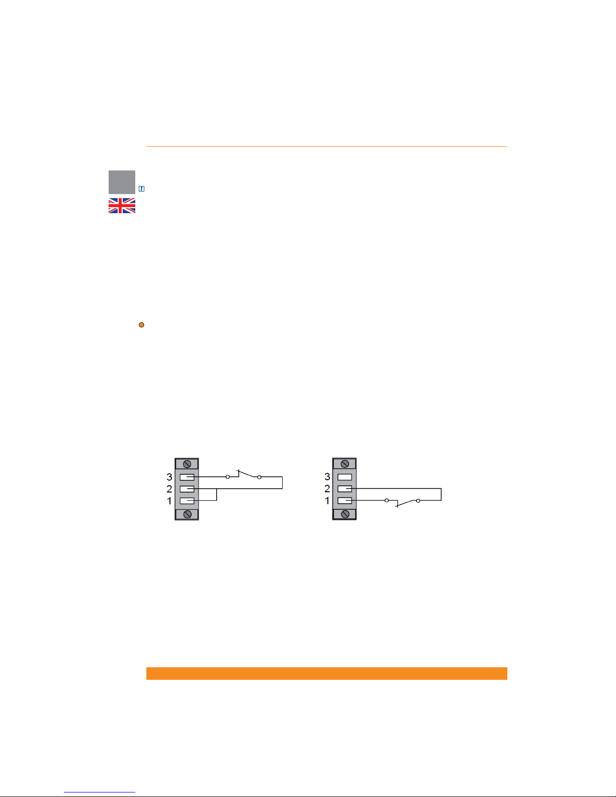
The external connection to the RPO/ROO circuit is located on the rear side of the unit and is composed of
three connector pins, as shown in the next gures.
The unit comes out of the factory with a wire which connects pins 1 and 2. For normal UPS operation, these
pins must be kept connected.
In order to use the Remote Power Off (RPO) functionality, please remove this wire and connect a normally
closed volt-free contact between pins 1 and 2. When this contact is open, the UPS will disconnect all loads
and shut down. To return to normal operation, disconnect the unit from AC mains power, close the contact
and re-start the unit following the procedure outlined in section 4.4.3.2.
In order to use the Remote On Off (ROO) functionality, please connect a wire between pins 1 and 2 (the
UPS comes out of the factory with that wire) and connect a normally closed volt-free contact between pins
2 and 3. When this contact is open, the UPS will disconnect all loads. After that, if the contact is closed the
unit will re-start and restore power to the connected loads.
For other details regarding ROO/RPO operation, please see section 4.1.6.
Page 33
31
Chloride Active
UK
5 Communication Interfaces
The UPS is equipped with a serial interface (RS232 and USB ports) and a communication interface slot.
These interfaces can be used for:
- Direct communication between UPS and workstation/server
- Integration of the UPS as client into a network with centralized monitoring via a ManageUPS SNMP
adapter in the interface slot
- Transfer of operational states to external alarm systems via volt-free contacts (with interface volt-free
contact card, available as accessory, in the interface slot).
The necessary communication software packages and interface cables and cards are either bundled with
the unit or available as accessories.
5.1 Serial Interface
Two serial interfaces are available: DB9 port (RS232) and USB port.
NOTE: both ports cannot be used at the same time.
5.2 DB9 port
The 9-pole SUB-D connector (pin contacts) contains RS232 compatible signals.
NOTE: this interface is electrically isolated from all other circuits.
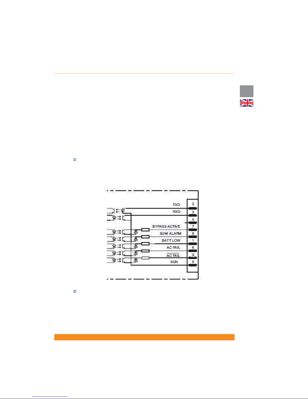
Apart from the RS232 interface, ve opto-coupled alarm signals are available as open-collector outputs. Pin
distribution is as follows (see previous gure):
- SGN at pin 5: this connection point serves as a reference for all signals
- RxD at pin 3 and TxD at pin 2: correspond to the normal assignment of an RS232 interface
- BATTERY LOW at pin 1: this output is active when the battery capacity is below the pre-alarm level
Page 34

32
UK
Chloride Active
945044.066
(please see section 4.2 for details on selection of this level) or when the remaining back-up time is less than
two minutes.
- AC FAIL (low-active at pin 9 and high-active at pin 6): this signal is active when the mains voltage at the
UPS input is not present for at least 10 seconds or the mains voltage exits the tolerance range. The signal
is cancelled 850ms following mains restoration.
- BYPASS ACTIVE at pin 7: This signal is active when the device has been switched to bypass, the inverter
is blocked and the power is supplied from the mains supply.
- SUM ALARM at pin 8: this output is low when one of the alarms “BATTERY LOW”, “AC FAIL” or “BYPASS
ACTIVE” is active.
5.3 USB port
As with the RS232 interface, the USB port facilitates the protocol-data transfer. The USB port included with
this UPS is classi ed as HID (Human Interface Device).
5.4 Interface Slot
The interface slot can be tted with optional various cards. The connectors, designation and codes placed
in the slot will therefore depend on the type of interface card used. A detailed description is enclosed with
the interface cards which are available as accessories.
Interface cards available:
- SNMP adapter card (ManageUPS) for integrating the UPS into a network
- Volt-free contacts card
Please consult the available literature about these accessories or please ask your closest sales centre.
Page 35

33
Chloride Active
UK
6 Maintenance
6.1 Cleaning
Do not use scouring powder or plastic-dissolving solutions to clean the UPS.
Do not allow liquid to get inside the UPS.
Make sure that the air vents on the UPS are not obstructed. Remove dust from the air vents with a vacuum
cleaner.
Clean the outside of the UPS housing by wiping with a dry or slightly damp cloth.
6.2 UPS storage
For extended storage at ambient temperatures higher than 25ºC, the batteries should be charged for ve
hours once every four months. At higher storage temperatures it is advised that this period be reduced to
two months.
To charge batteries it is not necessary to unpack the unit. Simply connect the UPS to an appropriate power
source using the appropriate opening in the packaging and allow the batteries to charge for about ve
hours. After charging, note the date when recharging was performed on the UPS packaging.
6.3 Battery testing
The UPS does not require maintenance by the user; however, batteries should be checked periodically.
The UPS will automatically perform a battery self-test once a week. If a problem is discovered, the battery
fault LED will illuminate or the LCD Display will show an error message. See section 7 (“Troubleshooting”) if
a problem is found.
The frequency of testing can be changed via LCD Display or user software. Select battery self-test to be
performed monthly, weekly, daily or none.
6.4 Battery replacement
ATTENTION: the load attached to the UPS will not be protected against loss of input power during this
procedure
6.4.1 Replacing the UPS internal batteries
For replacement of batteries locates in a service access area:
- Servicing of batteries should be performed or supervised by personnel knowledgeable about batteries and
the required precautions.
- When replacing batteries, replace with the same type and number of batteries or battery packs.- Do not
dispose of batteries in a re. The batteries may explode.
- Do not open or mutilate batteries. Released electrolyte is harmful to the skin and eyes. It may be toxic
- A battery can present a risk of electrical shock and high short-circuit current. The following precautions
should be observed when working on batteries:
Remove watches, rings, or other metal objects.
Use tools with insulated handles.
Wear rubber gloves and boots.
Do not lay tools or metal parts on top of batteries
Disconnect charging source prior to connecting or disconnecting battery terminals.
Determine if battery is inadvertently grounded. If inadvertently grounded, remove source from
ground. Contact with any part of a grounded battery can result in electrical shock. The likelihood of such
shock can be reduced if such grounds are removed during installation and maintenance (applicable to
Page 36
34
UK
Chloride Active
945044.066
equipment and remote battery supplies not having a grounded supply circuit).
The UPS does not require maintenance by the user; however, battery maintenance is recommended
in accordance with IEEE Recommended Practice for Maintenance, Testing and Replacement of ValveRegulated Lead-Acid (VRLA) batteries for Stationary Applications (IEEE Std 1188-1996). When the
batteries expire, trained battery service personnel must replace them. A certi ed disposal/recycling
company should carry out disposal/recycling of the UPS and/or batteries. Exhausted rechargeable batteries
are classi ed as “harmful toxic waste” and as such the law demands that they be disposed of/recycled by
an authorized recycling center.
The manufacturer’s service center is fully equipped to deal with such batteries, in accordance with the law
and with the greatest respect for the environment. Contact your customer service representative to arrange
for maintenance and/or battery replacement.
The typical battery life cycle is 3 to 5 years, at an ambient temperature of 25ºC. However, battery life is also
dependant on the frequency and duration of mains failures or battery discharge cycles.
The BATTERY TEST (see section 6.3 “Battery Testing”) should be carried out periodically (6 to 12 months)
in order to ascertain the general conditions of the batteries.
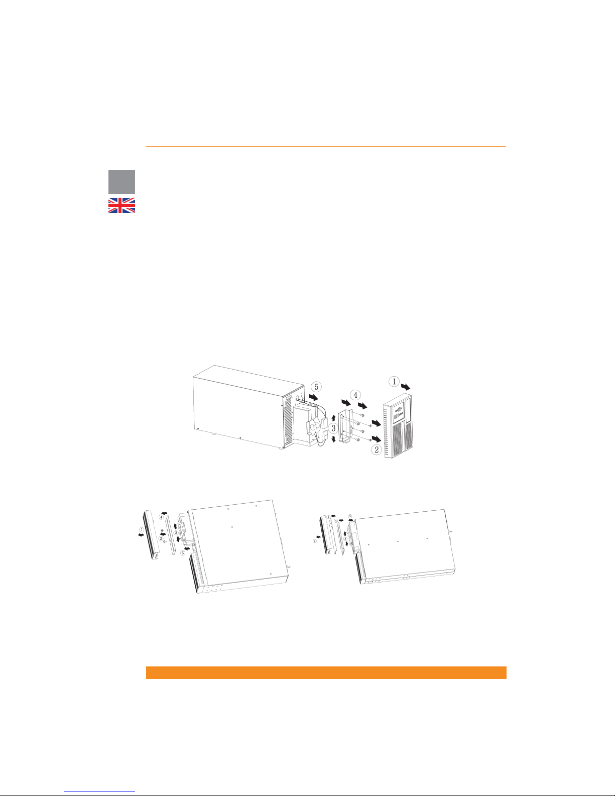
To replace internal batteries, place the UPS manually in bypass mode (see “Forced Bypass Procedure” on
section 4.4.4) and follow the steps illustrated in the next gures:
Tower models
1/1.5kVA rack/tower models 2/3kVA rack/tower models
Page 37

35
Chloride Active
UK
Tower units Rack/Tower units
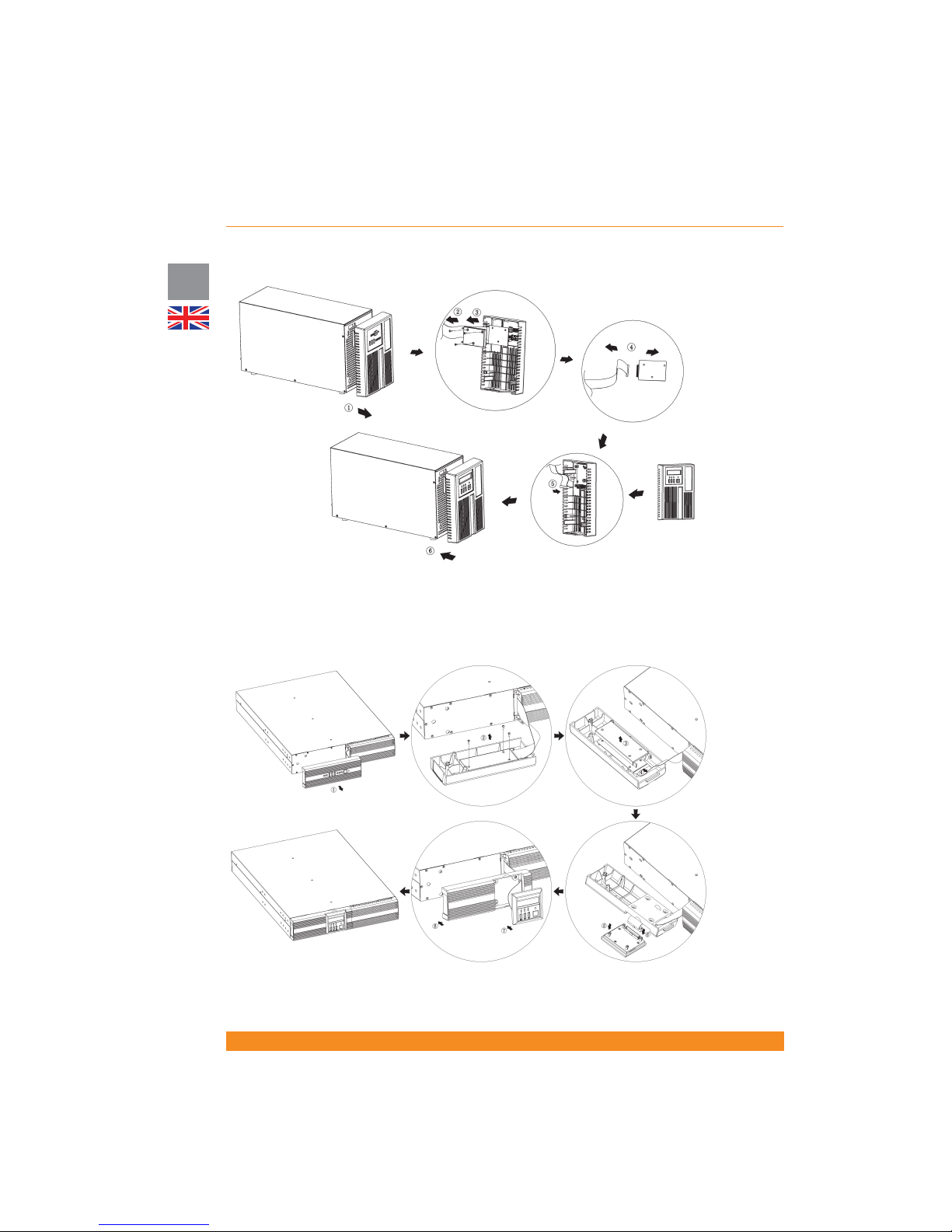
5) Take the new front panel with the LCD Display
and connect the at cable to the box with the LCD
Display (the cable must be in the same position as
in the old front panel)
6) Insert the new front panel in the UPS
5) Take the new front panel with the LCD Display and
pull out the box containing the LCD Display
6) Connect the at cable to the box with the LCD
Display (the cable must be in the same position as
in the old front panel)
7) Insert the box with the LCD Display in the front
panel
8) Insert the new front panel in the UPS
6.4.2 Battery disposal
The typical battery life cycle is 3 to 5 years, at an ambient temperature of 25ºC, but is also dependant on
the frequency and duration of mains failures.
Once the battery has reached the end of its useful life, follow the procedure for battery replacement (section
6.4.1).
After the batteries are replaced, a certi ed disposal/recycling company should carry out disposal/recycling
of the used batteries.
Exhausted rechargeable batteries are classi ed as “harmful toxic waste” and as such the law demands that
they be disposed of /recycled by an authorized recycling center.
The manufacturer’s service center is fully equipped to deal with such batteries, in accordance with the law
and with the greatest respect for the environment. Contact your customer service representative to arrange
for maintenance and/or battery replacement.
6.5 Front Panel with LCD Display Installation
WARNING: Installation must be carried out only by quali ed technicians.
Depending on your local market, the UPS can include a front panel based on LED indicators or a front
panel with a LCD Display. For units which include a front panel based on LED indicators as standard, front
panels with LCD display are available as accessory. These front panels have to be ordered separately.
In order to replace the front panel with LED indicators with the front panel with LCD display, the following
steps (illustrated in the next gures) have to be followed:
WARNING: Before performing this installation, ensure that the inverter is switched off and the input power
cord is disconnected. Wait until all LEDs turn off (this may take around 1 minute after disconnection of the
UPS) prior to performing this installation.
1) Pull out the front panel with LED indicators
2) Unscrew the box containing the LED indicators from the front panel
3) Remove the box
4) Disconnect the at cable from the box (please pay attention to the position of the cable)
Page 38
36
UK
Chloride Active
945044.066
Tower models
Rack/Tower models
Page 39

37
Chloride Active
UK
7 Troubleshooting
If, in spite of the high reliability of this unit, problems should occur, please check the following points before
contacting the responsible customer service representative:
- Is the mains voltage present at the UPS input?
- Is the input fuse defective or have circuit breakers tripped?
If you contact the responsible customer service representative, please have the following information ready:
- Unit information (model, product code/MLBF, serial number as per nameplate)
- An exact description of the problem (what loads are being operated, does the problem occur regularly or
sporadically, etc)
For description of the indicators mentioned below, please see chapter 4.2.
Problem Possible Cause Corrective Actions
No indication
No alarm
(UPS switched off)
Mains switch switched off Switch on mains switch
No mains voltage present Have mains inspected by quali ed electrician
Input fuse blown or input
circuit breaker tripped
Replace with fuse of same type or switch on
circuit breaker. If the problem persists, contact the
responsible customer service representative
UPS Overload LED blinks/
buzzer beeps at intervals (or
LCD Display shows overload
message)
UPS in bypass
Overload warning: UPS is
overloaded
(Unit on Line Mode)
Check the power drawn by the equipment and
disconnect any short-circuited or non-priority devices
UPS Overload LED blinks/
buzzer beeps continuously
(or LCD Display shows
overload message)
Load is dropped
Overload fault: UPS is
overloaded
(Unit on Battery Mode)
Check the power drawn by the equipment and
disconnect any short-circuited or non-priority devices
Re-start the UPS
Battery Fault LED blinks/
buzzer beeps at intervals (or
LCD Display shows battery
fault message)
A battery fault was detected
during the automatic battery
test
Check that battery connector is properly seated
Replace the battery module
Battery Fault LED blinks/
buzzer sound long beep
about once every hour
The battery is at end of
life, runtime on battery is
compromised
Reset alarm by pressing buttons 5 and 6 for 3
seconds (units with LED indicators)
Reset the alarm by pressing ESC button for 3
seconds (units with LCD Display)
Replace the battery module
Site Wiring Fault Detection
LED blinks, Site Wiring Fault
E/D LED is ON, buzzer
sounds continuously (or LCD
Display shows Site Wiring
Fault message)
Phase reversal (line and
neutral) has been detected
on input power
Pull out mains plug and plug back in correctly
UPS Fault LED illuminates,
buzzer beeps continuously
(or LCD Display shows fault
message)
UPS error
Contact the responsible customer service
representative
Overheating Decrease ambient temperature
Autonomy less than speci ed
The fuse switch of the battery
extensions is in the “OPEN”
position
Move the fuse switch to the “ON” position
Batteries are not fully
charged
Charge batteries and test backup time. If the
problem persists, contact the responsible customer
service representative
Batteries are defective
Contact the responsible customer service
representative
Charging device is defective
Contact the responsible customer service
representative
No communication between
UPS and PC
Wrong serial connection cable Check whether the correct cable has been used
Interface on the PC is being
used by another process or
is defective
Check whether other software/service is accessing
the interface on the PC; try selecting a different
serial interface
Interference on the data cable Lay cable differently/Re-install cabling
Page 40
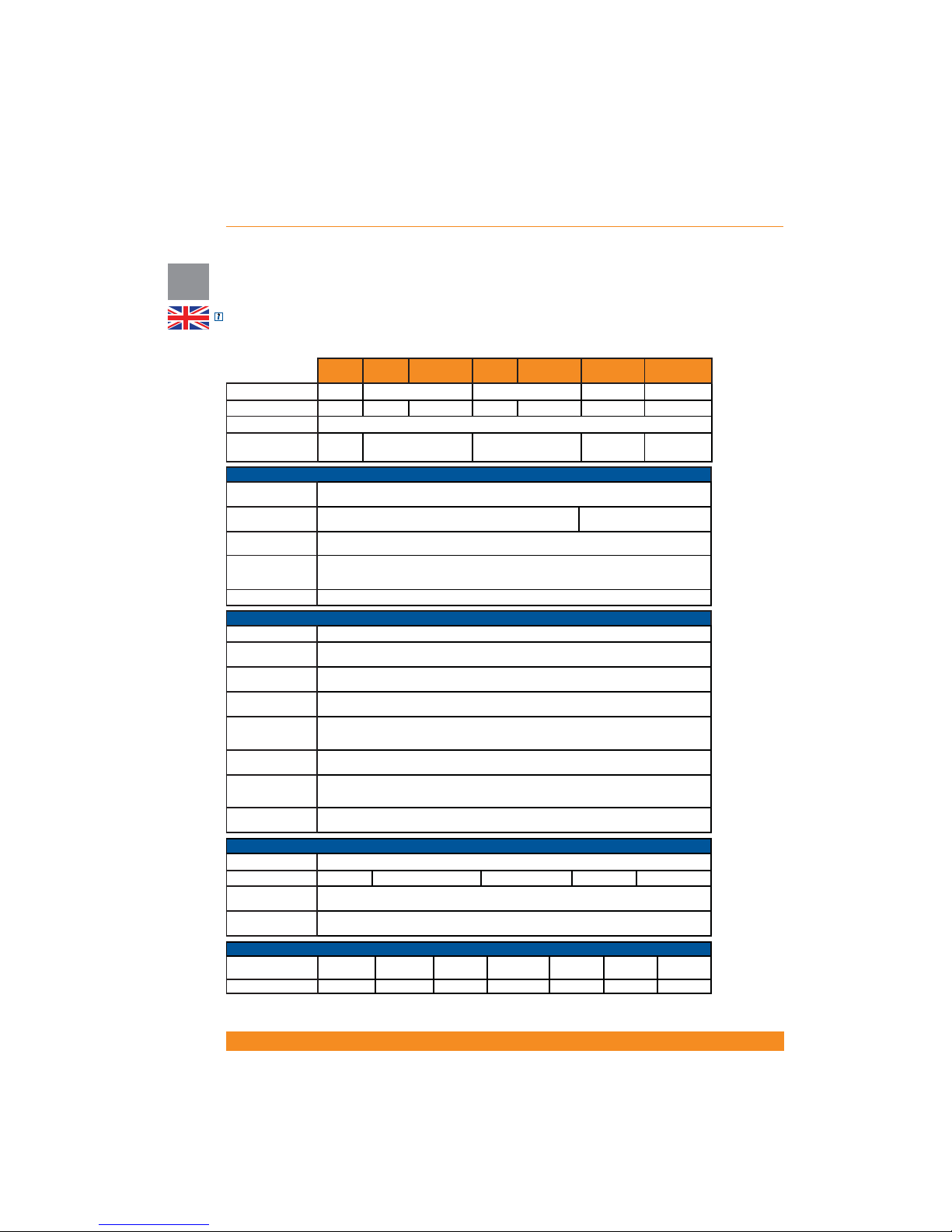
38
UK
Chloride Active
945044.066
8 Speci cation and back-up times
8.1 Speci cation
NOTE: We reserve the right to modify the information in these tables without prior notice.
8.1.1 Uninterruptible Power Supplies
Active
700 T
Active
1000 T
Active
1000 RT
Active
1500 T
Active
1500 RT
Active
2000 RT
Active
3000 RT
UPS Rating 700VA 1000VA 1500VA 2000VA 3000VA
Housing Tower Tower Rack/Tower Tower
Rack/Tower Rack/Tower Rack/Tower
Technology Advanced on-line double conversion
Output Power
(VA/W)
700/630
1000/900(*) 1500/1350(*)
2000/1800(*)
3000/2700(*)
INPUT
Nominal input
voltage (VAC)
200-240V
Operative input
voltage range (VAC)
120V-284V (depending on output load)
140-284V (depending on
output load)
Nominal input
frequency (Hz)
50/60Hz auto-selection
Operative input
frequency range
(Hz)
50/60Hz +/-5% (40/70Hz if Frequency Converter Mode is activated)
Input power factor 0,99 (batteries charged)
OUTPUT
Waveform
Pure sinusoidal
Nominal output
voltage (VAC)
200(**) / 208(**) / 220 / 230(default) / 240 V (con gurable via user software and optional LCD
Display) (250 V under request)
Voltage regulation
(%)
3%
Output frequency
(Hz)
50/60Hz ±0,5% (same as input or selectable in Frequency Converter Mode)
Harmonic distortion
(linear/non-linear
load) THDv
Max. 4% / Max. 8%
Transfer time (line-
battery-line) (s)
0
Overload capacity
(line mode, output
power factor 0.9)
<110% warning // 111-130%: 12 seconds (UPS to bypass) // >130%: 1,5 seconds (UPS off)
Shortcircuit
protection
Yes
BATTERIES
Type
Sealed maintenance-free lead acid (VRLA)
Arrangement
1x2x7,2Ah
1x3x7,2Ah 1x3x9Ah
1x6x7,2Ah 1x6x9Ah
Advanced Battery
Care
Yes
Battery
management
Battery pack auto detection, automatic runtime calculation, protection against deep discharge
MECHANICAL
Size (WxHxD, mm)
157x245x438 157x245x438
438x86
(2U)x482
157x245x488
438x86
(2U)x482
438x86
(2U)x657
438x86
(2U)x657
Weight (kg) 13 15 18 18
20
26 31
Page 41
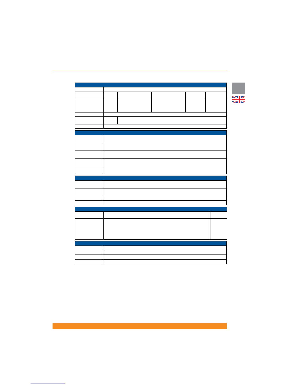
39
Chloride Active
UK
GENERAL
Bypass
Yes (automatic)
Ef ciency in line
mode (%)
86% 86% 86%
88% 90%
Maximum Acoustic
Noise in on-line
mode at 1 meter
(dB)
40
41 41 47 47
Variable fan speed
Yes
External battery
packs
No
Yes
Color
Grey Anthracite (RAL7016)
CONNECTIVITY
Communication
Ports
1xDB9 (RS232 signals and status signals), 1xUSB (***)
Communication
Slot
1xslot for SNMP/TCP-IP/Web interface or volt-free contacts card accessory
Remote Power Off
(RPO)
Yes
Remote On/Off
(ROO)
Yes
Status signals
Opto-coupled, open-collector signals available at DB9 port: Battery Low, AC Fail, Bypass Active,
SUM Alarm
ENVIRONMENTAL
Operating
temperature
0 - 40 ºC
Storage
temperature
-25 ºC / +50 ºC without batteries, -15ºC / +40ºC with batteries
Altitude 0-3000m
Relative humidity 10% to 90%
CONNECTIONS
Input
1 x IEC320 C14 (10A)
1 x IEC320
C20 (16A)
Output 6 x IEC320 C13 (10A), 3 of them controllable (2 groups)
6 x IEC320
C13 (10A),
3 of them
controllable
(2 groups)
1 x IEC320
C19 (16A)
NORMATIVES
CE Mark
Yes
Safety EN 62040-1, EN 60950 (RD), TÜV, CB report, UL/cUL
EMC IEC62040-2, class C2; IEC61000-4-3/3/4/5/6/8/11; VDE160; IEC61000-2-2
Performance EN62040-3
(*)Output power with external battery packs is – 1000VA models: 1000VA/800W, 1500VA models:
1500VA/1200W, 2000VA models: 2000VA/1600W, 3000VA models: 3000VA/2400W.
(**) For output nominal voltage 200V, there is a power de-rating of 20% (the unit’s nominal power is
reduced by 20%). For output nominal voltage 208V, there is a power de-rating of 10% (the unit’s nominal
power is reduced by 10%).
(***) Both ports cannot be used simultaneously.
Page 42
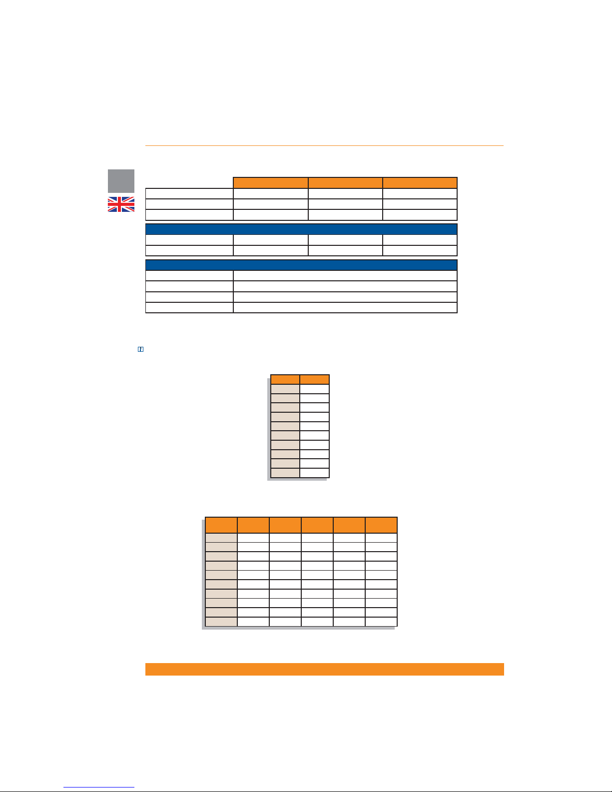
40
UK
Chloride Active
945044.066
8.1.2 Battery Packs
BP-A1000/1500-T BP-A1000/1500-RT BP-A2000/3000-RT
Housing
Tow e r
Rack/Tower Rack/Tower
Battery arrangement
2x3x7,2Ah
2x3x7,2Ah 2x6x9Ah
Protection
Breaker 70A/80Vdc
Breaker 70A/80Vdc Breaker 70A/80Vdc
MECHANICAL
Size (WxHxD, mm)
157x245x438
438x86(2U)x438 438x86(2U)x657
Weight (kg)
20
32 52
ENVIRONMENTAL
Operating temperature 0 - 40 ºC
Storage temperature -15 ºC / +40 ºC
Altitude 0-3000m
Relative humidity 10% to 90%
8.2 Runtime charts
Theoretical values with fully charged batteries and resistive load.
NOTE: The maximum quantity of external battery packs that can be connected to the UPS is four.
Active 700 T:
Load UPS
UPS
+ 1 BP
UPS
+ 2 BP
UPS
+ 3 BP
UPS
+ 4 BP
80W 63 min 239 min 438 min 661 min 861 min
160W 37 min 158 min 254 min 397 min 476 min
240W 26 min 91 min 197 min 262 min 372 min
320W 20 min 69 min 145 min 212 min 263 min
400W 15 min 55 min 97 min 174 min 220 min
480W 13 min 45 min 80 min 136 min 191 min
560W 11 min 38 min 69 min 99 min 161 min
640W
9 min 33 min 60 min 86 min 130 min
720W 7 min 29 min 51 min 75 min 99 min
800W 6 min 25 min 46 min 67 min 89 min
Active 1000 T and Active 1000 RT:
Load UPS
55W 51 min.
110W 35 min.
170W 24 min.
225W 18 min.
280W 15 min.
335W 12 min.
390W 10 min.
450W 8 min.
505W 7 min.
560W 5 min.
Page 43
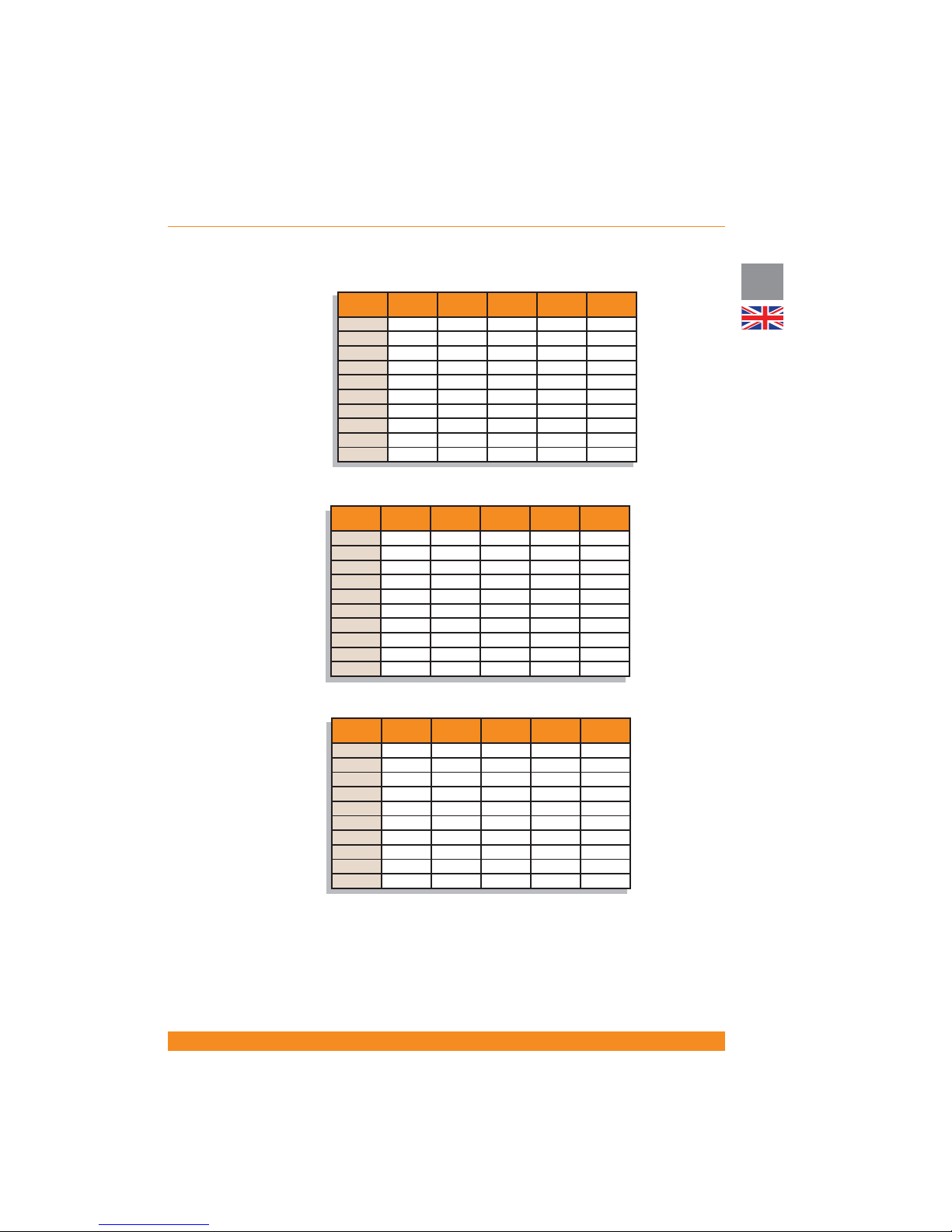
41
Chloride Active
UK
Active 1500 T and Active 1500RT:
Load UPS
UPS
+ 1 BP
UPS
+ 2 BP
UPS
+ 3 BP
UPS
+ 4 BP
120W 42 min 170 min 268 min 409 min 497 min
240W 25 min 84 min 180 min 234 min 331 min
360W 17 min 58 min 108 min 183 min 225 min
480W 13 min 44 min 78 min 129 min 183 min
600W 10 min 34 min 62 min 90 min 140 min
720W 8 min 26 min 51 min 74 min 98 min
840W 7 min 24 min 43 min 63 min 83 min
960W
5 min 21 min 37 min 55 min 72 min
1080W 4 min 18 min 32 min 48 min 64 min
1200W 3 min 16 min 28 min 42min 56 min
Load UPS
UPS
+ 1 BP
UPS
+ 2 BP
UPS
+ 3 BP
UPS
+ 4 BP
160W 63 min 231 min 406 min 558 min 754 min
320W 37 min 163 min 236 min 358 min 445 min
480W 26 min 97 min 195 min 237 min 327 min
640W 19 min 73 min 153 min 207 min 237 min
800W 15 min 58 min 108 min 177 min 213 min
960W 13 min 48 min 86 min 146 min 190 min
1120W 11 min 40 min 73 min 114 min 166 min
1280W
9 min 35 min 63 min 93 min 142 min
1440W 7 min 30 min 55 min 81 min 116 min
1600W 6 min 27 min 49 min 71 min 96 min
Active 2000 RT:
Load UPS
UPS
+ 1 BP
UPS
+ 2 BP
UPS
+ 3 BP
UPS
+ 4 BP
240W 42 min 173 min 238 min 371 min 456 min
480W 26 min 90 min 182 min 226 min 282 min
720W 18 min 62 min 123 min 185 min 218 min
960W 14 min 47 min 84 min 141 min 185 min
1200W 11 min 37 min 66 min 98 min 150 min
1440W 8 min 31 min 55 min 80 min 115 min
1680W 7 min 26 min 47 min 68 min 92 min
1920W
5 min 23 min 40 min 59 min 78 min
2160W 4 min 20 min 35 min 52 min 68 min
2400W 3 min 18 min 31 min 46 min 60 min
Active 3000 RT:
Page 44

42
DE
Chloride Active
945044.066
1. Sicherheit
1.1 Bestimmungsgemäße Verwendung
1.2 Allgemeine Warnungen
1.3 Sicherheitshinweise
1.4 Batterie-Sicherheit
1.5 Umweltbezogene Anmerkungen
1.6 Anmerkung zur EU-Konformitätserklärung
1.7 Verpackung
2. Über dieses Handbuch
2.1 Einführung
2.2 Geräte-Übersicht
2.3 Symbole
2.4 Dokumentationsstruktur
3. Setup und Installation
3.1 Lieferung
3.2 Auspacken
3.3 Lieferumfang
3.3.1 Tower -Geräte (USV)
3.3.2 Tower -Geräte (Batteriepakete)
3.3.3 Rack/Tower -Geräte (USV)
3.3.4 Rack/Tower -Geräte (Batteriepakete)
3.4 Lagerung
3.5 Handhabung
3.6 Umgebungsbedingungen
3.7 Boden-Belastung
3.8 Belastung des Racks
3.9 Lüfterkühlung
3.10 Installationsdaten
3.11 Rack-Montage für USV bzw. Batterieschrank (nur RT-Modelle)
3.12 Boden-Montage für USV bzw. Batterieschrank für externe Batterien (Nur RT-Modelle)
3.12.1 Montage der USV (alleine)
3.12.2 Montage der USV plus externer Batterie
4. Betrieb und Inbetriebnahme
4.1 Theoretischer Hintergrund
4.1.1 Netzbetrieb
4.1.2 Batteriebetrieb
4.1.3 Bypass-Betrieb
4.1.4 ECO-Modus
4.1.5 Frequenzkonverter-Modus
4.1.6 Andere Betriebsdetails
4.1.7 Blockdiagramm
4.2 Display und Gerätelemente-Beschreibung
4.2.1 Geräte mit LED-Indikatoren
4.2.1.1 Beschreibung der Elemente
4.2.1.2 Betrieb
4.2.1.3Indikatoren
4.2.2 Einheiten mit LCD-Display
4.2.2.1 Menüs und Funktionen
4.2.2.2 Warnmeldungen und Fehleranzeigen
4.3 Rückseite
4.3.1Tower-Geräte
44
44
44
44
45
46
46
46
47
47
47
48
48
49
49
49
49
49
49
49
50
50
50
50
51
51
51
51
51
53
53
53
54
54
54
54
54
54
54
55
55
56
56
56
57
58
59
60
62
62
62
Page 45

43
Chloride Active
DE
4.3.2 Rack/Tower-Geräte
4.4 Inbetriebnahme und Abschalten
4.4.1 Elektrische Vorbereitungsarbeiten
4.4.2 Anschlüsse
4.4.2.1 Anschluss externer Batteriepakete
4.4.2.1 Anschluss an das Versorgungsnetz
4.4.3 USV-Inbetriebnahme
4.4.3.1 USV-Erstinbetriebnahme
4.4.3.2 Normale USV-Inbetriebnahme
4.4.4 Interner Bypass
4.4.5 ECO-Modus Aktivierung/Deaktivierung
4.4.6 Frequenzkonverter-Modus aktivieren
4.4.7 USV abschalten
4.4.8 Remote Power Off (RPO) / Remote On Off (ROO)
5. 5.Kommunikationschnittstellen
5.1 Serielle Schnittstelle
5.2 DB9 Port
5.3 USB Port
5.4 Schnittstellensteckplatz
6. Wartung
6.1 Reinigung
6.2 USV-Lagerung
6.3 Batterietest
6.4 Batterietausch
6.4.1 Die internen Batterien der USV austauschen
6.4.2 Entsorgen der Batterie
6.5 Installation Frontblende mit LCD Anzeige
7. Fehlerbehebung
8. Technische Spezi kationen und Laufzeit-Diagramme
8.1 Spezi kationen
8.1.1 USV-Geräte
8.1.2 Batteriepakete
8.2 Laufzeit-Diagramme
64
65
65
65
65
66
66
66
67
67
67
68
68
68
69
69
69
70
70
71
71
71
71
71
71
73
73
75
76
76
76
78
78
 Loading...