

Page 1
UK
Page 2

Chloride Active
UK
1
Page 3
Chloride Active
ENGLISH
DEUTSCH
ESPAÑOL
FRANÇAIS
ITALIANO
PORTUGUÊS
UK
DE
E
FR
I
P
1
Page 4

Chloride Active
UK DE
All rights, including rights of translation,
reproduction by printing, copying or similar
methods even by printing, are reserved.
Offenders will be liable for damages.
All rights, including rights created by patent
grant of registration of utility model or design,
are reserved.
Delivery subject to availability. Right of
technical modifi cation reserved.
E FR
Reservados todos los derechos, incluso el
derecho de la traducción completa o parcial,
la reimpresión, la reproducción por copias
o por otros métodos análogos.
Las infracciones darán derecho a una
indemnización por daños sufridos.
Reservados todos los derechos especialmente en caso de la concesión de patentes
o de modelos de utilidad.
Entrega sometida a disponibilidad.
Reservado el derecho de establecer
modifi caciones técnicas.
I P
Tutti i diritti, incluso quelli di traduzione,
riproduzione di stampa, copia, concessione
di licenze e di utilizzo e simili, anche solo di
parti del testo, sono riservati.
I trasgressori seranno perseguiti per
danni.
La consegna è soggetta alla disponibilità.
L’azienda si riserva il diritto di variare
qualunque informazione tecnica riportata.
Alle Rechte vorbehalten, insbesondere (auch
auszugsweise) die der Übersetzung, des
Nachdrucks und Wiedergabe durch Kopieren
oder ähnliche Verfahren. Zuwiderhanlungen
verpfl ichten zu Schadenersatz.
Alle Rechte vorbehalten, insbesondere für
den Fall der Patenterteilung oder der GMEintragung.
Lieferung je nach Verfügbarkeit. Technische
Änderungen vorbehalten.
Touts droits réservés, y compris pour la
traduction, la réproduction même partielle par
impression, photocopie ou autres méthodes
analogues.
Les infractions sont passibles de
poursuites.
Tous droits réservés, y compris ceux issus de
l’attribution d’un brevet ou de l’enregistrement
d’un modéle ou d’un dessin d’utilité.
Livraison en fonction des disponibilités.
Siemens se réserve le droit d’apporter des
modifi cations sans préavis.
Todos os direitos reservados, em especial o
direito de traduçao (também parcialmente),
reproduçao, completa ou de partes
por reimpressão, cópias ou métodos
similares.
Os infratores estarão sueitos a ressarcir
os prejuicios.
Todos os direitos reservados, incluindo
a concessão de patentes e utilizaçao
de modelos. Entregas são sujeitas à
disponibilidade. Reservados os direitos de
realizar modifi caçoes técnicas.
2
945044.066
Page 5

Chloride Active
UK
UK
DE
E
FR
P
OPERATING MANUAL
BEDIENUNGSANLEITUNG
MANUAL DE USUARIO
MANUAL UTILISATEUR
I
MANUALE D’USO
MANUAL DE INSTRUÇÕES
4
42
80
118
156
194
3
Page 6

Chloride Active
UK
1. Safety
1.1 Intended use
1.2 General Warnings
1.3 Safety Notices
1.4 Battery Safety
1.5 Environmental Considerations
1.6 Notices Regarding the EU Declaration of Conformity
1.7 Repacking of Unit
2. About This Manual
2.1 Introduction
2.2 Device Overview
2.3 Symbols
2.4 Documentation Structure
3. Setup and Installation
3.1 Delivery
3.2 Unpacking
3.3 Scope of Delivery
3.3.1 Tower Units (UPS)
3.3.2 Tower Units (Battery Packs)
3.3.3 Rack/Tower Units (UPS)
3.3.4 Rack/Tower Units (Battery Packs)
3.4 Storage
3.5 Handling
3.6 Environmental Conditions
3.7 Floor Loading
3.8 Rack Loading
3.9 Ventilation
3.10 Installation Data
3.11 Rack-Mounting the UPS or External Battery Cabinets (RT Models Only)
3.12 Floor-Mounting the UPS or External Battery Cabinets (RT Models Only)
3.12.1 Mounting the UPS Only
3.12.2 Mounting the UPS plus One External Battery
4. Operation and Commissioning
4.1 Theory of Operation
4.1.1 Line Mode
4.1.2 Battery Mode
4.1.3 Bypass Mode
4.1.4 ECO Mode
4.1.5 Frequency Converter Mode
4.1.6 Other Operating Details
4.1.7Block Diagram
4.2 Front Panel Indicators and Operating Elements Description
4.2.1Units with LED Indicators
4.2.1.1 Description of the elements
4.2.1.2 Operation
4.2.1.3 Indicators
4.2.2Units with LCD Display
4.2.2.1 Menus and Functionalities
4.2.2.2 Warnings and Fault Indicators
4.3 Rear Side
4.3.1Tower Units
6
6
6
6
7
7
8
8
9
9
9
10
10
11
11
11
11
11
11
11
12
12
12
12
13
13
13
13
13
15
15
15
16
16
16
16
16
16
16
17
17
18
18
18
19
20
21
22
24
24
24
4
945044.066
Page 7

Chloride Active
4.3.2 Rack/Tower Units
4.4Commissioning and Shutdown
4.4.1 Electrical Preparations
4.4.2 Connections
4.4.2.1 External Battery Packs Connection
4.4.2.2 Power Connections
4.4.3 Start-Up Procedure
4.4.3.1 Initial UPS Start-Up Procedure
4.4.3.2 Normal Start-Up Procedure
4.4.4 Forced Bypass Procedure
4.4.5 ECO Mode Activation/Deactivation Procedure
4.4.6 Frequency Converter Mode Procedure
4.4.7 UPS Shutdown Procedure
4.4.8 Remote Power Off (RPO) / Remote On Off (ROO)
5. Communication Interfaces
5.1 Serial Interface
5.2 DB9 Port
5.3 USB Port
5.4 Interface Slot
6. Maintenance
6.1 Cleaning
6.2 UPS Storage
6.3 Battery Testing
6.4 Battery Replacement
6.4.1 Replacing the UPS internal batteries
6.4.2 Battery Disposal
6.5 Front Panel with LCD Display Installation
7. Troubleshooting
26
27
UK
27
27
27
28
28
28
29
29
29
30
30
30
31
31
31
32
32
33
33
33
33
33
33
35
35
37
8. Technical Specifi cations & Runtime Charts
8.1 Specifi cations
8.1.1 Uninterruptible Power Supplies
8.1.2 Battery Packs
8.2 Runtime Charts
38
38
38
40
40
5
Page 8

Chloride Active
UK
1. Safety
1.1 Intended use
This unit serves as an uninterruptible power supply (UPS) for connected loads. The unit is in compliance with all
relevant safety regulations concerning information technology equipment, for use in an offi ce environment.
Depending on the type and rating of the UPS unit, certain confi gurations of battery extensions may be connected.
These battery packs may only be connected to the compatible basic UPS unit.
1.2 General Warnings
WARNING: We consider the safety of personnel to be of paramount importance. For this reason, it is essential
that procedures relating to safety in this manual be carefully reviewed before commencing work, and properly
adhered to thereafter. The User or Operator may intervene in the operation of the UPS provided that the
instructions laid out in the section 3 (“Setup and Installation”) are strictly followed.
WARNING: Even when all switches and/or circuit breakers are open, dangerous voltages are present within this
unit. There are no user-serviceable parts inside. Only factory authorized personnel may carry out any operation
that requires protection panels to be opened and/or removed. Any repairs or modifi cations by the user may
result in out-of-warranty repair charges, unsafe electrical conditions or violation of electrical codes.
WARNING: In order to comply with UL requirements, a disconnection device shall be available at the UPS
output (note: the output plug can be considered as a disconnection device).
WARNING: In order to comply with UL requirements; to reduce the risk of fi re, connect the UPS input only
to a circuit provided with branch circuit overcurrent protection for 20 amperes rating in accordance with the
National Electric Code, ANSI/NFPA 70)
1.3 Safety Notices
WARNING: Read the following safety notices carefully! Disregard of these safety notices may endanger your
life, your health, the reliability of your unit and the security of your data.
- Transport the unit only in suitable packaging (protected against jolts and shocks).
- If the UPS is moved from a cold environment to a warmer operating location, condensation may occur. Before
you switch on the unit it must be absolutely dry. An acclimatization period of at least two hours is required.
- The UPS must be installed in accordance with the environmental conditions specifi ed in sections 3.6 and
3.10.
- Even with all buttons in “OFF” position, the unit (UPS) is not isolated from the mains. To isolate completely
from the mains, the input power cord must be disconnected.
- This unit services power from more than one source. The output terminals and/or receptacles may have
voltage present even when the unit is unplugged. UPS’s present a different safety issue than most electrical
equipment because unplugging the unit puts it into battery mode. Unplugging the UPS does not remove
electrical charge.
- In case of interruption of the mains voltage, the integrated battery maintains the power supply to the user’s
equipment.
- Place all cords so that nobody can stand on them or trip over them. When connecting the unit to the power
supply, follow the instructions in section 3 (“Setup and Installation”).
- Make sure that no objects (e.g. necklaces, paper clips, etc) get inside the unit.
- In emergencies (e.g. damaged case, controls or power cables, penetration of liquids or foreign bodies) switch
off the unit, disconnect from mains and contact the responsible customer service representative.
- Do not connect equipment that will overload the UPS or demand DC current.
- When cleaning the unit, follow the instructions in section 6 (“Maintenance”).
- Data transmission lines should not be connected or disconnected during a thunderstorm.
- The sum of the leakage currents (currents in the earth conductor) from the UPS and connected loads must
not exceed the value of 3.5 mA.
- Remote Power Off (RPO) and Remote On Off (ROO) terminals are located on the rear side of the unit (see
section 4.4.8) When the relevant connections are open, the logic circuit will immediately shut down the UPS
output.
- When installing units in racks, do not allow racks to become “top heavy”. Install heaviest equipment (typically
the UPS and batteries) near bottom of rack, and install this equipment before installing equipment higher in
6
945044.066
Page 9

Chloride Active
the rack.
- This unit is equipped with a safety-inspected mains line and must only be connected to a grounded earthingcontact socket.
- Make certain that the socket on the unit or the earthing contact socket of the house installation is freely
accessible.
- This is a category C2 UPS product. In a residential environment, this product may
cause radio interference, in which case the user may be required to take additional measures.
1.4 Battery Safety
WARNING: The batteries installed in the UPS and within the battery packs contain electrolyte. Under normal
conditions the containers are dry. A damaged battery may leak electrolyte that can be dangerous in contact
with the skin and cause irritation to the eyes. Should this happen, wash the affected part with copious amounts
of water and seek immediate medical advice.
- Voltage is always present on the battery terminals.
- Even when discharged, a battery has the capacity to supply a high short circuit current, which, in addition to
causing damage to the battery itself and to associated cables, may expose the operator to the risk of burns.
- Batteries should not be kept in storage for periods exceeding 6 months at 25ºC without being recharged
(having been charged to 100% at the beginning of any such period). If these conditions are not respected
the performance of the battery can no longer be guaranteed. It is advisable to recharge the batteries at least
once every 4 months.
- Since new batteries often do not provide full capacity after an initial charge it may be necessary to carry out
a number of discharge/recharge cycles before optimum performance is achieved.
- In order to protect the environment, batteries must be disposed of in accordance with the regulations governing
disposal/recycling of toxic and harmful waste.
For replacement of batteries located in a service access area:
- Servicing of batteries should be performed or supervised by personnel knowledgeable about batteries and
the required precautions.
- When replacing batteries, replace with the same type and number of batteries or battery packs.
- Do not dispose of batteries in a fi re. The batteries may explode.
- Do not open or mutilate batteries. Released electrolyte is harmful to the skin and eyes. It may be toxic
- A battery can present a risk of electrical shock and high short-circuit current. The following precautions should
be observed when working on batteries:
·Remove watches, rings, or other metal objects.
·Use tools with insulated handles.
·Wear rubber gloves and boots.
·Do not lay tools or metal parts on top of batteries
·Disconnect charging source prior to connecting or disconnecting battery terminals.
·Determine if battery is inadvertently grounded. If inadvertently grounded, remove source from
ground. Contact with any part of a grounded battery can result in electrical shock. The likelihood
of such shock can be reduced if such grounds are removed during installation and maintenance
(applicable to equipment and remote battery supplies not having a grounded supply circuit).
1.5 Environmental Considerations
This unit contains batteries. Their disposal should be made in accordance with the applicable legislation in
your country.
The lead and acid contained by the batteries can be harmful for the environment.
The units should be disposed of at the end of their lifetime in accordance with the applicable legislation in
your country.
We take into consideration environmental aspects as a part of the design of our units, trying to minimize their
environmental impact. This implies using those technological advantages that allow reduction of the use of
hazardous substances and the generation of toxic and dangerous residues.
This manual includes recommendations created to optimize the operation of the unit and its components.
UK
7
Page 10

UK
Chloride Active
1.6 Notices regarding the EU Declaration of Conformity
This unit is in conformity with the following European directives:
73/23/EWG. Directive of the council for adaptation of the legal regulations of the member states regarding
electrical equipment for use within specifi c voltage limits, modifi ed by directive 93/68/EWG.
89/336/EWG. Directive of the council for adaptation of the legal regulations of the member states regarding
electromagnetical compatibility, modifi ed by directive 91/263/EWG, 92/31/EWG and 93/68/EWG.
Conformity is established through compliance with the following standards:
-EN 62040-1-1
-EN 62040-2
Additional information regarding adherence to these directives is included in the appendices NSR and EMC
of the EU Declaration of Conformity.
If needed, the EU Declaration of Conformity can be requested from the manufacturer.
1.7 Repacking of Unit
Do not pack the unit until at least two hours have elapsed since the last recharge.
Place the equipment in bags made of a material suffi ciently porous to allow it to breathe (e.g. 100μm
polyethylene).
Do not remove air from the packaging.
When packing unit for movement by common carrier, place in original or equivalent packaging container.
8
945044.066
Page 11
Chloride Active
2 About This Manual
2.1 Introduction
This manual contains information regarding the installation, operation and use of the Uninterruptible Power
Supply (UPS).
Consult this manual before installation of the equipment. This manual should be kept for later reference for
operation and maintenance of the UPS.
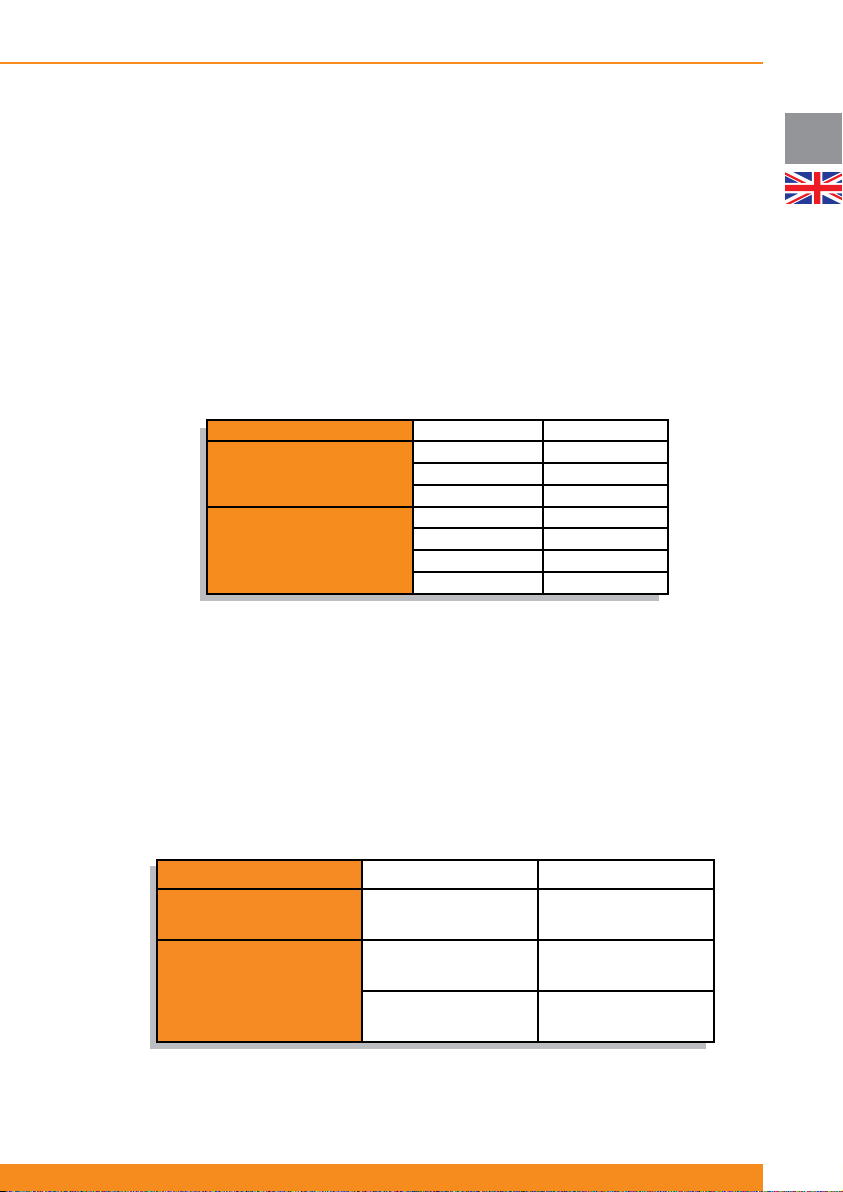
2.2 Device Overview
These UPS units are delivered with various nominal powers and in various housings.
The following table provides an overview of the various versions of the unit:
Housing Designation
Tower
(upright unit)
Rack/Tower convertible
(can be upright or rack-
mounting unit)
Depending on your local market, these units can include a front panel based on LED indicators or a front
panel with a LCD Display.
For units which include a front panel based on LED indicators as standard, front panels with LCD display are
available as accessory. These front panels have to be ordered separately. Installation of the front panel with
LCD display must be carried out by qualifi ed technicians. Please contact the responsible customer service
representative. For further details on installation, please see section 6.5.
The following battery packs are available:
Active 700 T 700 VA
Active 1000 T 1000 VA
Active 1500 T 1500 VA
Active 1000 RT 1000 VA
Active 1500 RT 1500 VA
Active 2000 RT 2000 VA
Active 3000 RT 3000 VA
Nominal Power
UK
Housing Designation Compatible UPS Unit
Tower
(upright unit)
Rack/Tower convertible
(can be upright or rack-
mounting unit)
BP-A1000/1500 T
BP-A1000/1500 RT
BP-A2000/3000 RT
Active 1000 RT
Active 1500 RT
Active 2000 RT
Active 3000 RT
Active 1000 T
Active 1500 T
9
Page 12

UK
Chloride Active
2.3 Symbols
ATTENTION: Indicates instructions, which if not observed, may endanger reliability of your UPS or the security
of your data.
WARNING: Indicates instructions, which if not observed, present risk of electric shock, may endanger your
life, your health, reliability of your UPS or the security of your data.
NOTE: Indicates instructions and comments that provide further details on the UPS and complement the
main text.
2.4 Documentation structure
These instructions can be supplemented with additional sheets, which e.g. describe specifi c extensions or
options.
10
945044.066
Page 13
Chloride Active
3 Setup and Installation
3.1 Delivery
This unit has been thoroughly checked before shipment. Upon receipt, check the packaging and ensure that
the contents are undamaged. Any damage must be reported to the shipper and any missing parts must be
reported to the supplier immediately.
3.2 Unpacking
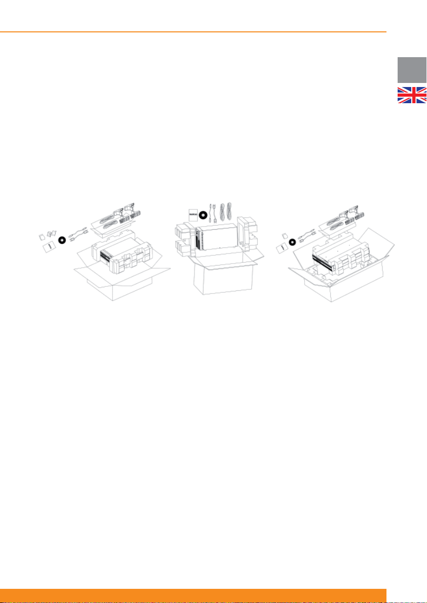
Care should be taken when removing the packaging in order to avoid damaging the unit. Check all packaging
materials to ensure that no items are discarded (please see below fi gures). Note that they are only descriptive
fi gures whose content is subject to changes according to local markets.
1 and 1.5kVA rack/tower units
Tower units
3.3 Scope of delivery
The following items are included within the packaging:
3.3.1 Tower units (UPS)
2 and 3kVA rack/tower units
UK
- 1 x this user manual
- 1 x UPS unit
- 1 x quickstart guide
- 1 x CD with user software
- 2 x connection cables IEC320 C14 (male) - IEC C13 (female) for the UPS output
- 1 x RS232 interface cable
- 1 x USB cable
3.3.2 Tower units (Battery Packs)
- 1 x Battery Pack unit
- 1 x battery extension cable
- 1 x battery pack detection cable for auto-detection of number of battery packs connected
3.3.3 Rack/Tower units (UPS)
- 1 x this user manual
- 1 x UPS unit
- 1 x quickstart guide
- 1 x CD with user software
- Connection cables as per below:
11
Page 14
Chloride Active
UK
1000, 1500 and 2000VA models 3000VA models
1 x connection cable Schuko
2 x connection cables IEC320
C14 (male) - IEC C13 (female)
for the UPS output
- 1 x RS232 interface cable
- 1 x USB cable
- 2 x front brackets for rack-mounting and required mounting hardware
- 2 x sets of tower feet for fl oor-mounting
- 2 x sliding rail kits for rack-mounting (optionally) and required mounting hardware
(male) - IEC320 C19 (female) for
the UPS input
1 x multisocket extension
IEC320 C20 (male) - 3 x Schuko
(female) for the UPS output
3.3.4 Rack/Tower units (battery packs)
- 1 x Battery Pack unit
- 1 x battery extension cable
- 1 x battery pack detection cable for auto-detection of number of battery packs connected
- 2 x front brackets for rack-mounting and required mounting hardware
- 2 x spacers to be assembled with the sets of tower feet for fl oor-mounting
- 1 x plate for securing the battery pack to the UPS for fl oor-mounting
- 2 x sliding rail kits for rack-mounting (optionally) and required mounting hardware
3.4 Storage
If it is not intended that the UPS be used within seven days of delivery, attention shall be paid to the storage
conditions.
The UPS should be stored in a clean, dry environment and away from temperature extremes. It is
recommended that the unit be stored in a temperature controlled, moderate humidity environment. The
table below provides the temperature and humidity storage limits:
Temperature limits
Relative humidity (non-
condensing)
-25ºC/50ºC (w/o batteries)
-15ºC/40ºC (with batteries)
10-90%
3.5 Handling
The UPS must be kept upright at all times and handled with care. Damage may be caused if dropped or
subjected to severe impact.
3.6 Environmental Conditions
The UPS tower version must be installed vertically. The UPS rack/tower version (RT hereinafter) can be
installed vertically or horizontally, depending on the desired arrangement.
In any case, it must be installed on a level and even surface and in an area protected from extremes of
temperature, water, humidity and the presence of conductive powder or dust (see section 3.10). Do not
stack units and do not place any objects on top of a unit.
The functional temperature range of the UPS is specifi ed in section 8 (“Technical Specifi cations”).
The ideal ambient temperature range is 15ºC to 25ºC.
Expected battery runtimes and battery life is defi ned at 20ºC. Increments of temperature above 25ºC will
reduce the expected battery life.
12
945044.066
Page 15
Chloride Active
3.7 Floor Loading
Taking into consideration the weight of the UPS and extension battery packs of Tower models and RT
models operating as Tower, it is necessary that the fl oor in the chosen location be capable of supporting the
weight of the units.
NOTE: Weights for the UPS and battery packs are shown in section 8 (“Technical Specifi cations”).
3.8 Rack Loading
Taking into consideration the weight of the UPS and extension battery packs of RT models that may be
mounted in an associated rack, it is necessary that the chosen cabinet be capable of supporting the weight
of the units.
NOTE: Weights for the UPS and battery packs are shown in section 8 (“Technical Specifi cations”).
3.9 Ventilation
It is necessary to leave a minimum space of at least 50 mm in front and rear of the UPS to allow a fl ow of
air.
Electrical maintenance and servicing requires access to the front and back of the UPS. Provide the
necessary space to allow service personnel access to the UPS.
3.10 Installation Data
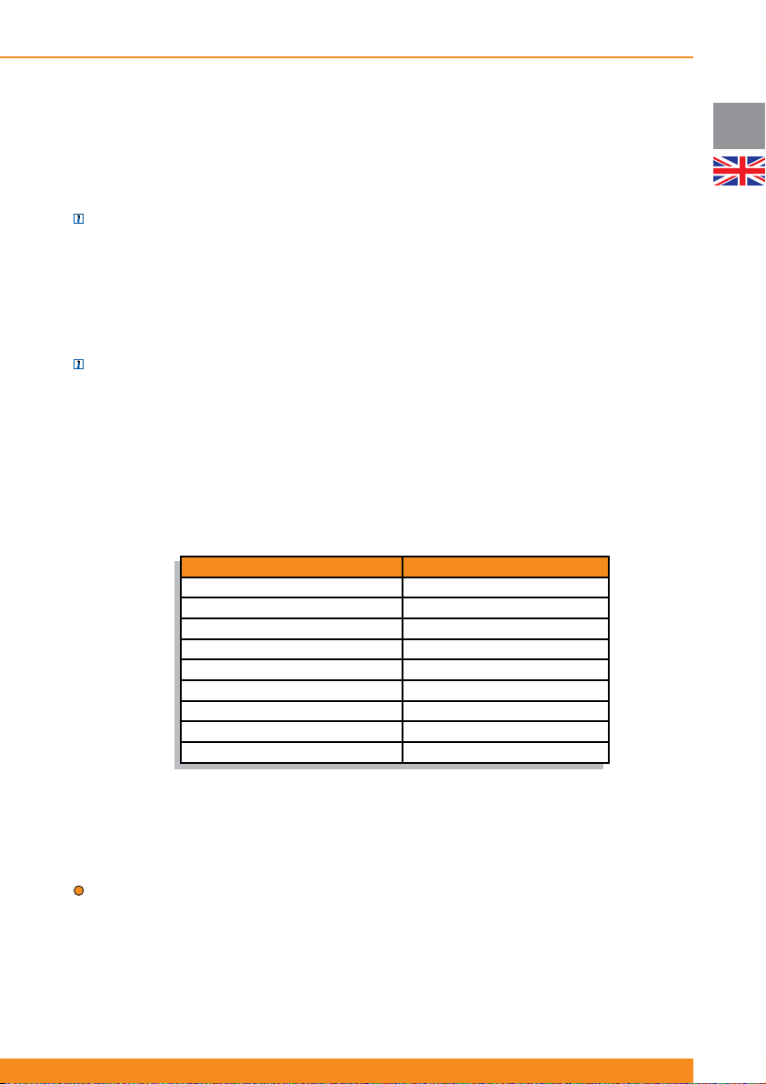
Item Specifi cation
Ambient temperature 0ºC to 40ºC
Relative humidity (non condensing) 20%-90%
Environment Controlled (offi ce or similar)
Max. altitude (w/o derating) 3.000 meters
Input power connection Rear
Output power connection Rear
Battery power connection Rear
Air inlet Front
Air outlet Rear
UK
3.11 Rack-Mounting the UPS or External Battery Cabinets (RT Models Only)
The Rack/Tower UPS’s and external battery packs can be rack-mounted in four-post frames. The UPS and
external battery packs use identical mounting hardware and the procedure for mounting either is the same.
ATTENTION: The UPS draws cooling air from the front. If the rack has a door on the front, make sure that
there is some clearance between the vents and the rack door.
Because of the weight and dimensions of these units (particularly the 2 and 3kVA models), it is strongly
recommended that two people lift the unit for rack-mounting. If only one person is available, it may be
possible to disconnect and take out the UPS internal batteries, rack-mount the UPS without batteries (less
weight) and re-connect the internal batteries once that the UPS is rack-mounted.
13
Page 16
UK
Chloride Active
Please use only the supplied fasteners to attach the supplied mounting brackets to the UPS or external
battery packs.
If external battery packs are included in your installation, please mount them fi rst and as low as possible.
Start with the lowest available position and work up. Your UPS should be installed last and end up on the
top of all the battery units for proper cable routing.
ATTENTION: Use all supplied mounting hardware on each UPS and external battery pack. NEVER depend
on lower devices to support other devices.
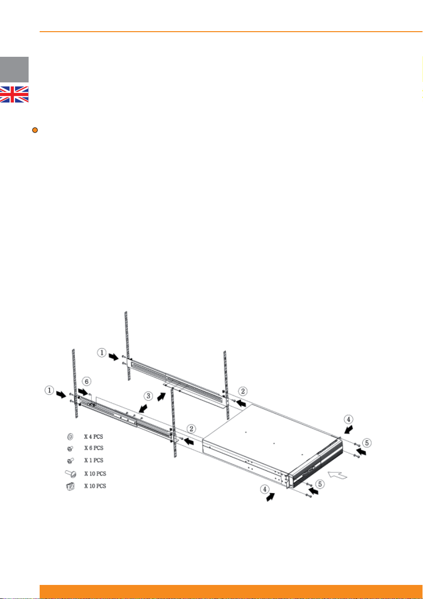
All mounting materials are available (bundled or optionally) to install the UPS into a rack. To prepare the
UPS and external batteries for use in a rack confi guration, fi rst install the sliding rails (optional accessory),
and then install the UPS and batteries following the steps below:
1. Attach rear of rails to rear of rack with two screws provided
2. Attach front of rails to front of rack with one screw provided
3. Assemble side rails and secure each rail together with three screws
4. Attach front brackets to each side of UPS with four screws on each side
5. Slide UPS into position in the rack and secure with two screws on each side of UPS
6. Attach rail to rear side of the UPS (fi xing point for safer transportation)
7. Repeat the above steps for each UPS or battery pack to be mounted
After mechanical installation is complete, please read section 4 for proper commissioning and operation of
the system.
14
945044.066
Page 17
Chloride Active
3.12 Floor Mounting the UPS or External Battery Cabinets (RT Models Only)
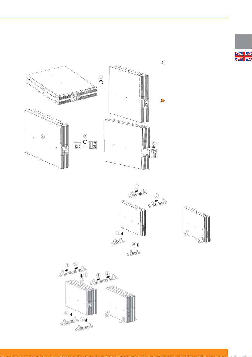
The RT UPS and external battery packs are designed to be fl oor standing as an alternative to rack
mounting.
NOTE: (only for units with front
panel with LCD display). The
LCD Display can be rotated to
the adequate position when it is
fl oor-mounted as illustrated in the
next fi gure.
ATTENTION: Use all supplied
mounting hardware on each UPS
and external battery
After mechanical installation is
complete, please read section
4 for proper commissioning and
operation of the system.
3.12.1 Mounting the UPS
only
UK
Assemble the two sets of feet
included with the UPS and place
the UPS between feet as shown
in the next fi gures.
3.12.2 Mounting the UPS
plus One External Battery
Assemble the two sets of feet
with the spacer provided and
place the UPS and battery pack
between feet as shown in the
next fi gure. Then secure UPS
and battery pack with plates and
screws provided.
15
Page 18

Chloride Active
UK
4 Operation and Commissioning
4.1 Theory of Operation
ATTENTION: This UPS is supplied with standard power cords and receptacles suitable for its use in your
area of operation. It may be installed and operated by non-technician personnel.
4.1.1 Line Mode
In use, the UPS is connected between AC input power and the load. The operation of this UPS is based
on the on-line double conversion principle in which the input AC power is fi rst converted to DC, and
secondarily converted back to a sine wave of a fi xed frequency and voltage to supply controlled power
to the load. This UPS topology is used to prevent the critical load from suffering a variety of power line
problems, including the total loss of input AC power.
4.1.2 Battery Mode
In the event of a mains failure, the maintenance-free batteries will continue to provide an uninterrupted
supply of energy to the load. In practice, most mains failures are of relatively short duration. Therefore,
the energy stored in the UPS’s batteries is, in most cases, suffi cient to ensure continuous operation of the
connected systems until the mains power is re-established. In the event of a long lasting mains failure, the
UPS can be utilized with shutdown software to enable a controlled shutdown of connected systems.
The most reliable method for determining the estimated battery runtime is the use of the LCD Display or the
application of the user software or SNMP network card. With this software, the estimated remaining battery
capacity is indicated before and during an AC power failure. These products also allow for automated
shutdown procedures that can shut down the attached devices after safely closing open applications
programs and the operating system. After return of the mains voltage, the UPS automatically restores
power to the connected equipment and starts recharging the batteries.
4.1.3 Bypass Mode
If the UPS is in bypass mode, the load is supplied directly from the AC mains via the internal automatic
bypass.
The unit automatically starts up in bypass when it is connected to the AC mains, supplying voltage
immediately to the load. It is necessary to press the Inverter ON button to start the inverter and switch the
unit to line mode (normal operation).
In the event of an overload on the UPS or internal UPS failure, the load is immediately supplied directly
from the mains via this automatic internal bypass. As soon as normal status is re-established, an automatic
switch over to inverter operation is performed.
Alternatively, the unit can be forced to bypass by the user using the front panel buttons or LCD Display.
In this case, if the input parameters (voltage, frequency) go out of tolerances, the unit automatically shuts
down.
4.1.4 ECO Mode
When the ECO Mode is enabled and mains conditions are within tolerances, the output is fed directly from
the input via the internal bypass, thus achieving very high effi ciency values and therefore saving energy.
When ECO mode is activated and mains conditions go out of tolerances, the unit automatically feeds the
load through the inverter to keep the load protected.
When the unit is operating on ECO mode, the internal battery charger is working. Therefore, batteries are
kept charged.
For details on how to enable/disable this mode, please refer to 4.4.5.
4.1.5 Frequency Converter Mode
The UPS can operate as a frequency converter, providing 50Hz or 60Hz (whichever is selected) to the
output when the input frequency is within the 40-70Hz range.
16
945044.066
Page 19
Chloride Active
When the unit is operating in this mode, there is a 50% power de-rating. This means that only 50% of the
UPS nominal power can be used when operating in this mode.
If the unit is operating as a Frequency Converter, neither can ECO Mode be activated nor can the unit be
forced to Bypass Mode.
For details on how to enable/disable this mode, please refer to 4.4.6.
4.1.6 Other Operating Details
This section covers other functionalities featured by the unit. For operating details on them, please see
sections 4.2, 4.3 and 4.4.
a) Green Power Function: when the unit is on battery mode and there is no output load, the unit
automatically shuts down after fi ve minutes for battery and energy saving.
b) Cold Start: when this functionality is enabled, the unit has the capability to start up when mains power is
not present, thus powering the load directly from the batteries.
ATTENTION: When the UPS is started for the fi rst time, AC power must be present
c) Auto-Restart: when this functionality is enabled, the unit automatically starts up after autonomy time has
fi nished upon mains power comeback. Otherwise, it is necessary to start up the unit manually.
NOTE: assuming that this functionality is activated, if there is a mains failure just after the unit has
automatically started up, autonomy time will be short as the batteries have not been fully charged.
d) Site Wiring Fault detection: the unit can detect if input line and input neutral have been inverted and
report a fault in that case.
e) Battery test: the UPS can perform a battery test in two different ways: manually, upon user request, or
automatically, with a fi xed interval between tests.
f) Controllable outlets: this UPS includes two groups of output controllable sockets (outlet 1 and outlet 2).
Each group can be confi gured to automatically shut down when the remaining battery capacity goes below
a certain value (75%, 50%, 25% or 0%) or upon user request.
ATTENTION: It is suggested that the highest priority equipment be attached to the main outlets and that
lower priority loads be attached to the controllable outlets.
g) Remote On Off (ROO) / Remote Power Off (RPO): the unit has terminals on the rear side that allow the
user to remotely shut down and start up the unit (ROO) or remotely shut down the unit without the option of
re-starting it remotely (RPO). For operating details, please see section 4.4.8.
h) Compatibility with gensets: this UPS can operate with most of the gensets available in the market.
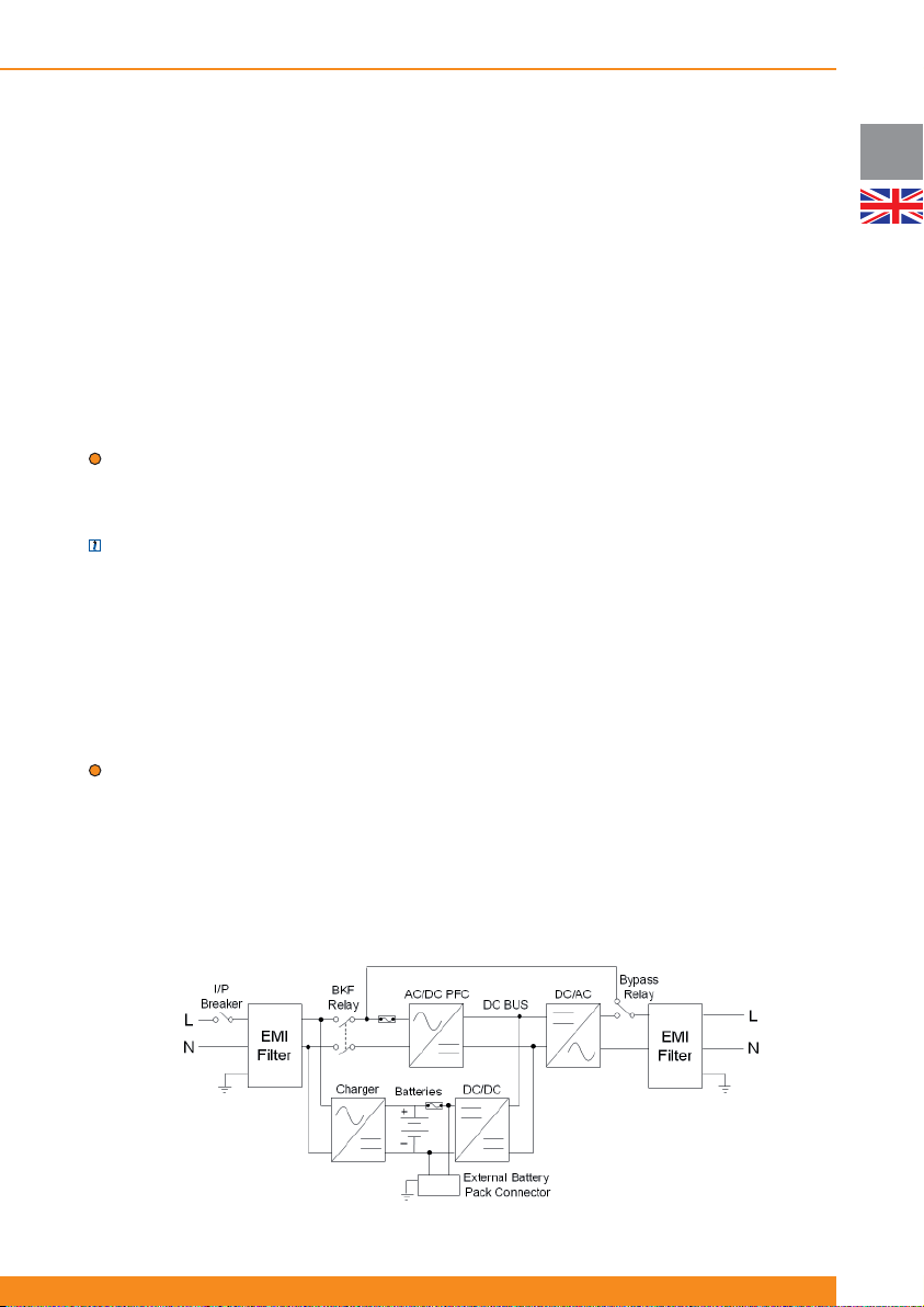
4.1.7 Block Diagram
UK
17
Page 20
UK
Chloride Active
4.2 Front Panel Indicators and Operating Elements Description
4.2.1 Units with LED indicators
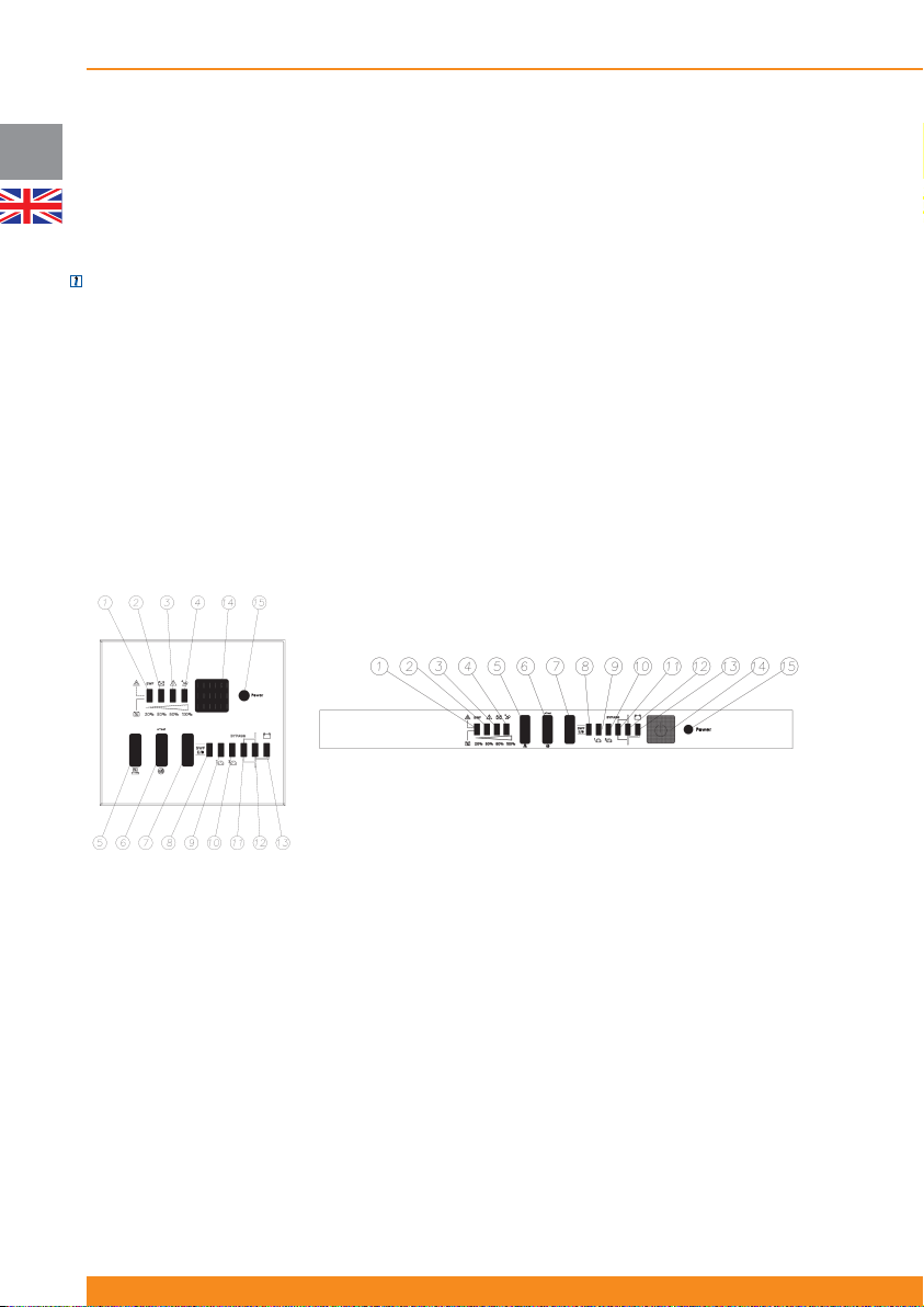
Depending on your local market, the UPS can be equipped with a front panel containing a series of
switches and indicator LED’s that provide the operator with the current status of the UPS and the ability to
change UPS operational mode.
NOTE: for units with front panels with LED indicators, front panels with LCD display are available as an
accessory and have to be ordered separately. For operation details about them please refer to section 4.2.2
4.2.1.1 Description of the elements
The front panel contains a series of switches and indicator LEDs that provide the operator with the current
status of the UPS and the ability to change UPS operational mode:
- Inverter ON/OFF switch and LED
- A simplifi ed block diagram of the UPS shows the current operational mode of the UPS (i.e. line mode,
battery mode, bypass mode)
- Two LED indicators show the current status (ON or OFF) of the controllable outlets 1 and 2.
- Four additional LEDs provide error status, UPS load percentage or battery charge percentage depending
on the associated front panel button status.
- Site Wiring Fault detection switch and LED
18
945044.066
1. Site Wiring Fault Detection LED
2. Battery Fault LED
3. UPS Fault LED
4. UPS Overload LED
5. Display Selection Button
6. LED Test/Alarm Reset Button
7. Site Wiring Fault E/D Button
8. Site Wiring Fault E/D LED
9. Outlet 1 ON/OFF LED
10. Outlet 2 ON/OFF LED
11. Bypass Mode LED
12. Line Mode LED
13. Battery Mode LED
14. Inverter ON/OFF Button
15. Inverter ON LED
Page 21
Chloride Active
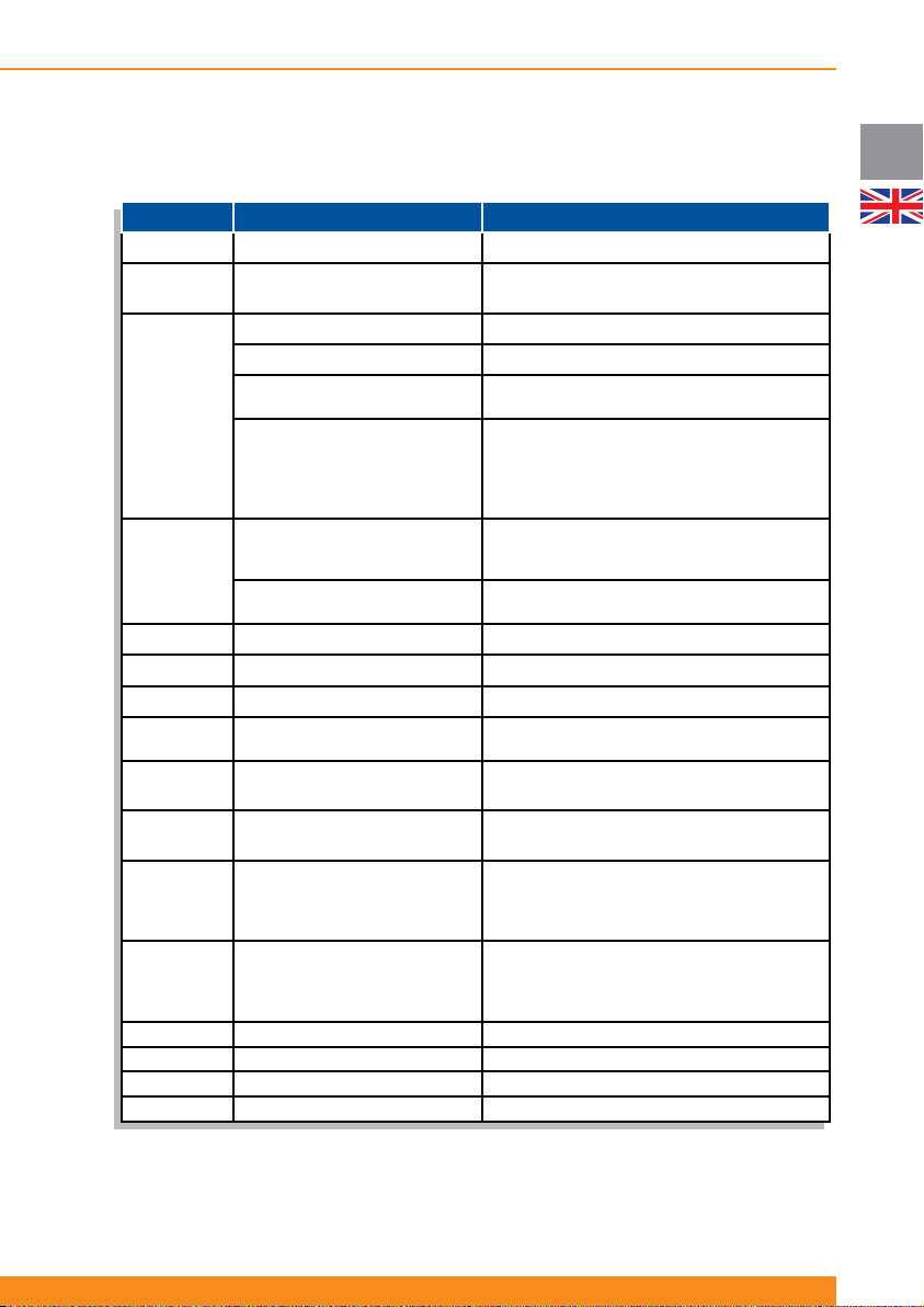
4.2.1.2 Operation
The following chart describes functions and operations of these buttons and LEDs
Button/LED Function Operation/Defi nition
Button 14 Inverter ON/OFF Button
Button 7 Site Wiring Fault E/D Button
Mute Buzzer (Alarm Reset) Press one second to mute the buzzer
LED test Press for LED test (all LEDs fl ashing)
Force the unit to bypass or
Button 6
Reset LCM Alarm (alarm which
Button 5
LED 1 (*) Site Wiring Fault Detection LED
LED 2 (*) Battery Fault LED
LED 3 (*)
LED 4 (*) UPS Overload LED
LEDs 1, 2, 3
& 4 (*)
LED 8
LED 9
LED 10
LED 11 Bypass Mode LED Indicates if the unit is on bypass mode (fl ashing)
LED 12 Line Mode LED Indicates if the unit is on line mode (ON)
LED 13 Battery Mode LED Indicates if the unit is on battery mode (ON)
LED 15 Inverter ON LED Indicates if the inverter is ON or OFF
Battery Capacity Level / Output
comeback
indicates end of estimated
battery life)
Show Output Load level
Cold Start Enable/Disable
UPS Fault LED
Load Level
Site Wiring Fault E/D LED Indicates if Site Wiring Fault detection is enabled
Outlet 1 ON/OFF LED
Outlet 2 ON/OFF LED
Press one second to switch on/off the inverter
Press seven seconds to enable/disable Site
Wiring Fault detection
Press buttons 6 and 5 for four seconds to force
the unit to bypass or to return from bypass
Press buttons 6 and 5 for three seconds to
reset this alarm (if the alarm is active, it is
necessary to push these buttons 4 more
seconds to switch the unit to bypass, as per
above functionality)
Press to show output load level on LEDs 1, 2
3 and 4 (by default they show battery capacity
level)
Press fi ve seconds to enable/disable cold start
functionality
Indicates if Site Wiring Fault has been detected
Indicates if a battery fault has been detected
Indicates if a UPS fault has been detected
Indicates if an output overload has been
detected
Indicates battery capacity level (by default), or
output load level if button 5 is pressed
or disabled (enabled: ON; disabled: OFF)
Indicates if group 1 of the output controllable
sockets is supplying power or not (supplying
power: ON; not supplying power: OFF; status
change in progress: fl ashing)
Indicates if group 2 of the output controllable
sockets is supplying power or not (supplying
power: ON; not supplying power: OFF; status
change in progress: fl ashing)
UK
(*) These LEDs show battery capacity level or output load level (depending on button 5) and normally they should be read
as a group. However, in case of certain events (SWF, Battery Fault, UPS Fault or UPS Overload), they pass to indicate it by
fl ashing and should be read individually.
19
Page 22

UK
Chloride Active
4.2.1.3 Indicators
The following chart describes visual and acoustic indications when certain conditions happen. For visual
indications, only the representative LEDs are shown (the others may be ON or OFF, depending on other
operative conditions).
LED display Indicators Acoustic UPS Condition
All LEDs fl ashing
three times
Three beeps
Start-up
sequence
LED 4 fl ashing.
LEDs 1, 2 & 3 off
LED 4 fl ashing.
LEDs 1, 2 & 3 off
LED 3 fl ashing.
LEDs 1, 2 & 4 off
LED 13 fl ashing
three times
LED 4 ON
LED 3 ON
LED 2 ON
LED 1 ON
LED 1 OFF
LED 2 OFF
LED 3 OFF
LED 4 OFF
LED 4 ON
LED 4 fl ashing.
LEDs 1, 2 & 3 off
LED 2 fl ashing.
LEDs 1, 3 & 4 off
LED 3 fl ashing.
LEDs 1, 2 & 4 off
Continuous
beep
Continuous
beep
Depending on
fault
Three beeps
Continuous
beep
One beep per
second
One beep per
second
One beep per
second
Overload fault
Inverter
shortcircuit fault
Other UPS fault
Line Mode to
Battery Mode
Remote Power
Off warning
Overload
warning
Battery
disconnected or
battery test fault
Charger fault
20
945044.066
LED 1 ON, LED
13 fl ashing
LED 2 fl ashing.
LEDs 1, 3 & 4 off
LED 8 ON
LED 1 fl ashing,
LEDs 2, 3 & 4
OFF. LED 8 ON
One beep
every three
seconds
One beep
every 30
minutes
-
Continuous
beep
Battery Low
LCM Alarm (end
of battery life)
Site Wiring
Fault detection
enabled
Site Wiring Fault
Detected
Page 23
Chloride Active
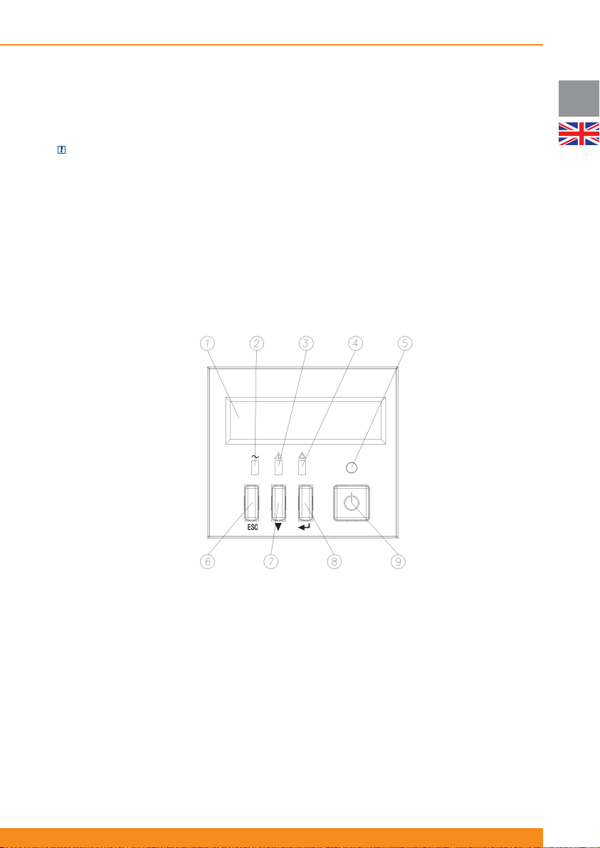
4.2.2 Units with LCD Display
Depending on your local market, the UPS can be equipped with a front panel with a LCD Display instead of
LED indicators.
NOTE: for units with front panels with LED indicators, front panels with LCD display are available as an
accessory and have to be ordered separately
1. Display
2. Mains LED (green): illuminates if mains input power is within tolerances
3. Bypass Mode/ECO Mode LED (orange): illuminates if the unit is in bypass (forced, due to ECO mode…)
4. Fault LED (red): illuminates if the unit is reporting a fault: battery fault, inverter fault, BUS fault…
5. Inverter ON LED (green): illuminates if the inverter is ON
6. ESC Button (goes up one level on the menu hierarchy). Note: press this button for three seconds to reset
the LCM alarm (alarm which indicates end of estimated battery life).
7. Scroll-Down Button (scrolls down through menus and submenus)
8. ENTER Button (goes down one level on the menu hierarchy or selects the displayed option)
9. Inverter ON/OFF Button (Switches on/off the inverter)
UK
21
Page 24
UK
Chloride Active
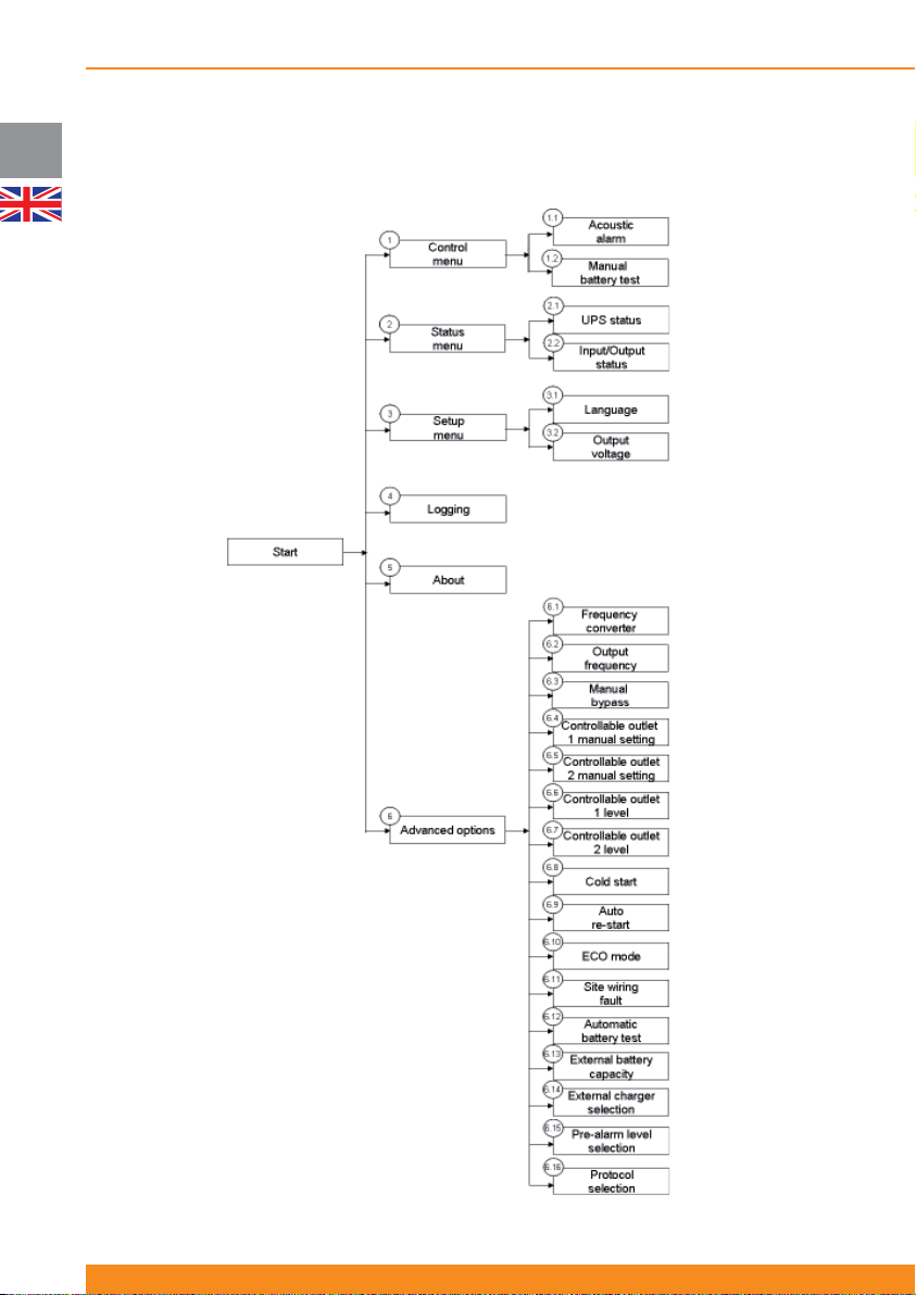
4.2.2.1 Menus and Functionalities
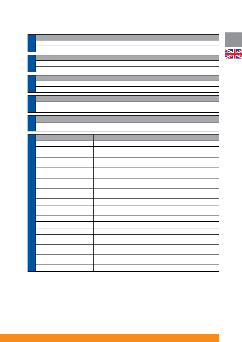
Functions available in the menus and sub-menus are explained below.
22
945044.066
Page 25
Chloride Active
Submenu Functionality
1.1 Acoustic Alarm Activation or deactivation of acoustic alarm (buzzer)
MENU 1.-
1.2 Manual Battery Test Performs a battery test when this option is selected
CONTROL
Submenu Functionality
2.1 UPS Status Displays global UPS Status (operation mode, faults, warnings…)
STATUS
2.2 Input/Output Status Displays input and output values (voltage, frequency, load…)
MENU 2.-
Submenu Functionality
3.1 Language Language selection (English, Spanish, Italian, French, Portuguese, German)
SETUP
3.2 Output Voltage Selects nominal output voltage (200V, 208V, 220V, 230V or 240V)
MENU 3.-
Functionality
Displays the last fi ve events (faults, warnings…) stored by the UPS and the runtime when they happened. These
MENU 4.-
LOGGING
ABOUT
MENU 5.-
6.4 Controllable Outlet 1 Manual
6.5 Controllable Outlet 2 Manual
MENU 6.- ADVANCED OPTIONS
6.14 External Charger Selection
Menu 6 includes options for advanced user and, consequently, access to this menu is protected with a password
(a certain combination of keys).
When this menu is selected, you will be asked to press the code keys (PRESS CODE KEYS (CHECK U.
MANUAL)). Correct code keys combination is:
Press ESC button and release it - press scroll-down button and release it - press ENTER button and release it.
If this sequence and combination of keys is followed, access to the menu will be granted and the display will
show ACCESS GRANTED ATTENTION! If not, an error message will show (ACCESS DENIED WRONG
Displays power rating, serial number of the UPS, fi rmware version and current unit runtime
Submenu Functionality
6.1 Frequency Converter Enables or disables this operation mode (please check 4.1.5 and 4.4.6 for more details)
6.2 Output Frequency Selects nominal output frequency: 50Hz or 60Hz (only frequency converter mode)
6.3 Manual Bypass Forces the UPS to bypass mode and vice-versa
Setting
Setting
6.6 Controllable Outlet 1 Level
6.7 Controllable Outlet 2 Level
6.8 Cold Start Enables/disables this functionality (start-up without mains power)
6.9 Auto Re-Start
6.10 ECO Mode Enables or disables this operation mode (please check 4.1.4 and 4.4.5 for more details)
6.11 Site Wiring Fault
6.12 Automatic Battery Test Sets automatic battery test interval (daily, weekly, monthly…)
6.13 External Battery Capacity
6.15 Pre-alarm Level Selection
6.16 Protocol selection Communication protocol selection for particular advanced applications
stored events are explained in section 4.2.2.2
Functionality
Switches on/off outlet 1 (1st group of output controllable sockets)
Switches on/off outlet 2 (2nd group of output controllable sockets)
Selects remaining battery capacity level (75%, 50%, 25% or 0%) below which
outlet 1 (1st group of output controllable sockets) automatically switches off
Selects remaining battery capacity level (75%, 50%, 25% or 0%) below which
outlet 2 (2nd group of output controllable sockets) automatically switches off
Enables/disables this functionality (automatic start-up after autonomy time has
Enables/disables this functionality (detection of input phase-neutral inversion)
Selects external battery capacity (Ah) for special / customized confi gurations,
in steps of 9Ah up to 250Ah (value selected pressing scroll-down button)
Selects the number of external battery chargers (available as accessory for
Selects the remaining battery capacity level (75%, 50%, 25% or 0%) below
fi nished and upon mains power comeback)
special / customized confi gurations) connected, from 1 to 3
which the “Battery Low” signal is activated
CODE KEYS).
23
UK
Page 26
UK
Chloride Active
4.2.2.2 Warning and fault indicators
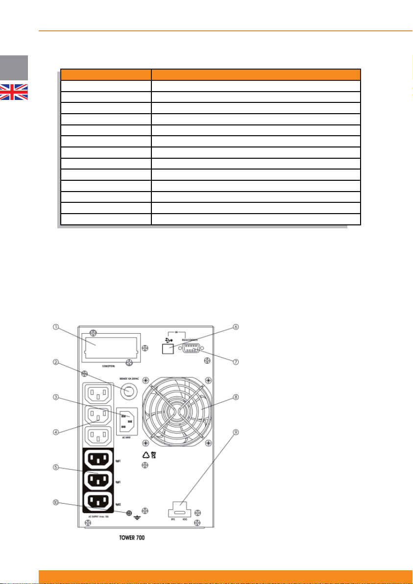
Display Message Description
RPO ACTIVE
BATTERY FAULT
INVERTER OVERLOAD
BYPASS OVERLOAD
FAN FAULT
CHARGER OVERVOLTAGE
DC BUS OVERVOLTAGE
DC BUS UNDERVOLTAGE
DC BUS UNBALANCE
INVERTER OVERVOLTAGE
INVERTER UNDERVOLTAGE
INVERTER SHORT
SITE WIR. FAULT
The LCD Display shows the last fi ve events stored and the runtime when they happened (menu 4). They
are listed from 1 to 5, being 1 the newest event and 5 the oldest event. Event 1 is the fi rst one to be
displayed and events from 2 to 5 are displayed sequentially by pressing the Scroll-Down button.
4.3 Rear Side
4.3.1 Tower units
Active 700 T:
UPS stopped because RPO (Remote Power Off) has been activated
Battery failure has been detected. Please check batteries.
Overload detected on the inverter (line mode or battery mode)
Overload detected when the unit is on bypass mode
Fan failure has been detected
Charger is delivering overvoltage (internal failure)
DC voltage on the DC bus too high (internal failure)
DC voltage on the DC bus too low (internal failure)
DC voltage on the DC bus unbalanced (internal failure)
Inverter is delivering overvoltage (internal failure)
Inverter is delivering undervoltage (internal failure)
Short-circuit on the inverter (internal failure)
Site wiring fault detected. Please check input wiring arrangement.
1. SNMP Slot
2. Input circuit breaker
3. Input power connection
4. Not controllable output sockets
5. Controllable outlets (2 groups)
6. USB port
7. RS232 port
8. Fan
9. ROO/RPO terminals
10. Earth screw
24
945044.066
Page 27
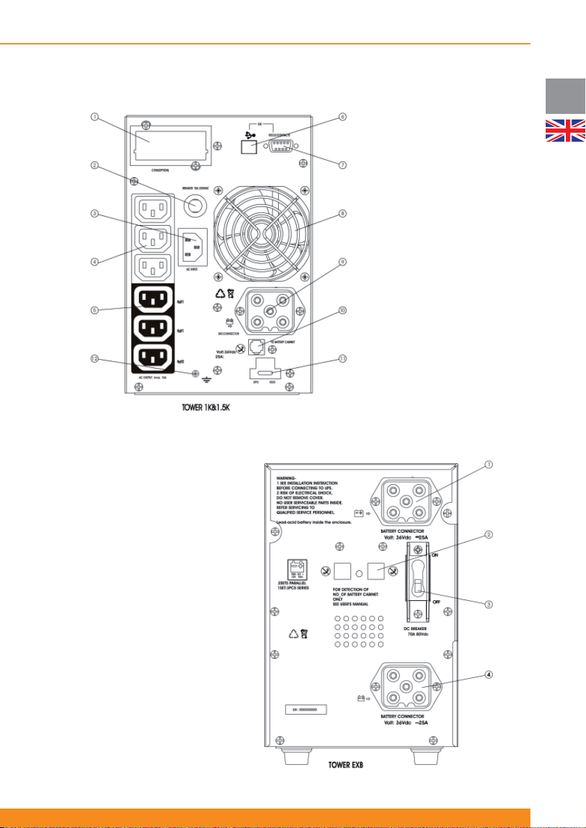
Active 1000 T and Active 1500 T:
BP-A1000/1500-T:
Chloride Active
1. SNMP Slot
2. Input circuit breaker
3. Input power connection
4. Not controllable output sockets
5. Controllable outlets (2 groups)
6. USB port
7. RS232 port
8. Fan
9. External battery pack connector
10. RJ11 port for battery pack
detection cable
11. ROO/RPO terminals
12. Earth screw
UK
1. Battery pack connector
2. RJ11 port for battery pack
detection cable
3. Circuit breaker
4. Battery pack connector
25
Page 28
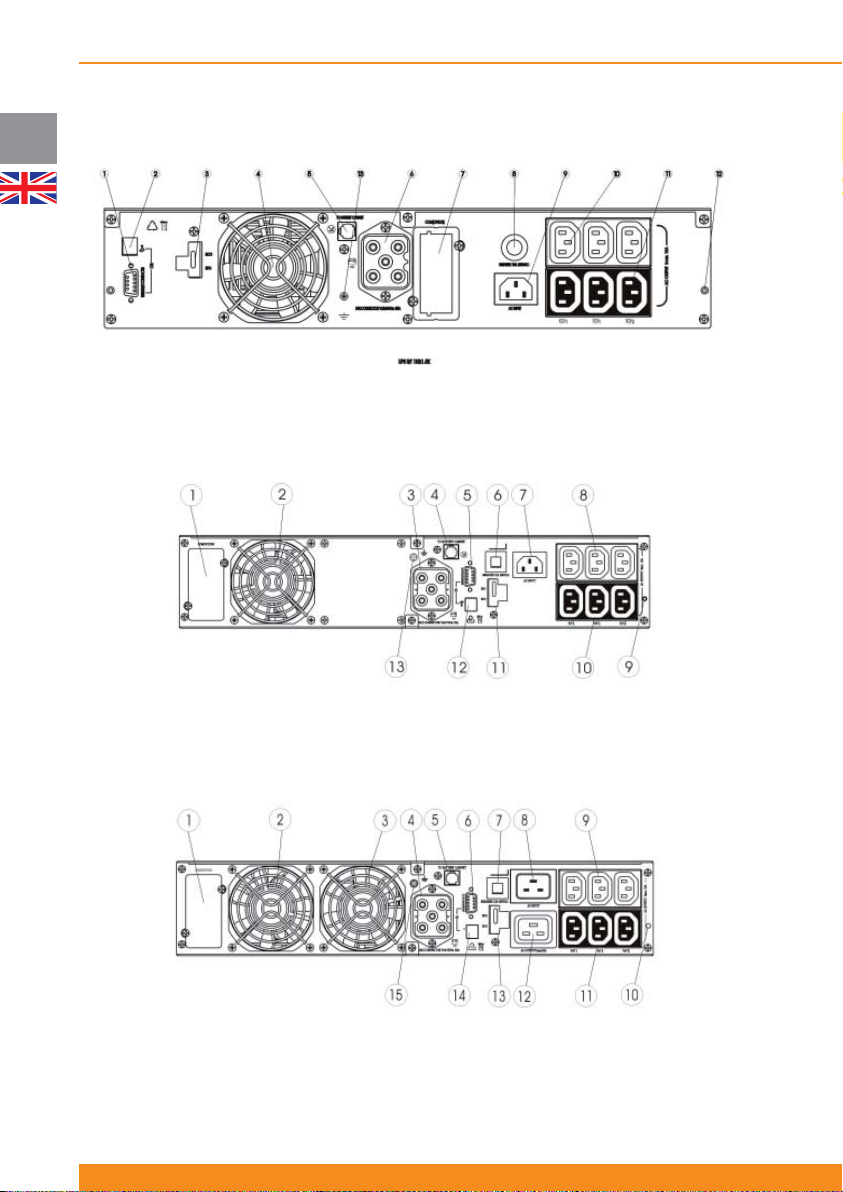
UK
Chloride Active
4.3.2 Rack/Tower units
Active 1000 RT and Active 1500 RT:
1. RS232 port
2. USB port
3. ROO/RPO terminals
4. Fan
5. RJ11 port for battery pack detection
cable
Active 2000 RT:
1. SNMP slot
2. Fan
3. External battery pack connector
4. RJ11 port for battery pack detection
cable
5. RS232 port
Active 3000 RT:
6. External battery pack connector
7. SNMP slot
8. Input circuit breaker
9. Input power socket
10. Not controllable output sockets
6. Input circuit breaker
7. Input power socket
8. Not controllable output sockets
9. Fixing point for sliding rail
10. Controllable outlets (2 groups)
11. ROO/RPO terminals
11. Controllable outlets (2 groups)
12. Fixing point for sliding rail
13. Earth screw
12. USB port
13. Earth screw
1. SNMP slot
2. Fan
3. Fan
4. External battery pack connector
5. RJ11 port for battery pack detection
cable
26
945044.066
6. RS232 port
7. Input circuit breaker
8. Input power socket
9. 10Amps not controllable output
sockets
10. Fixing point for sliding rail
11. 10Amps controllable outlets (2
groups)
12. 16Amps output socket
13. ROO/RPO terminals
14. USB port
15. Earth screw
Page 29
Chloride Active
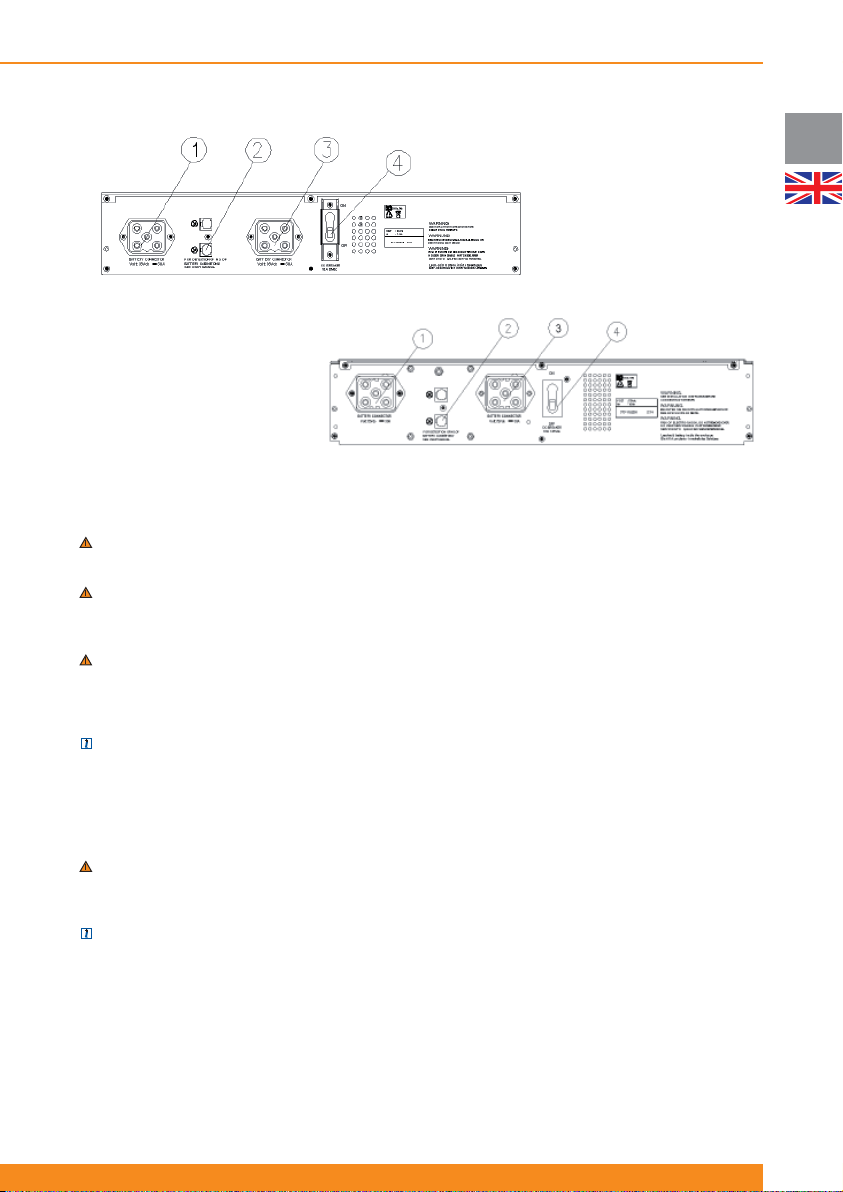
BP-A1000/1500-RT:
1. Battery pack connector
2. RJ11 port for battery pack detection
cable
3. Battery pack connector
4. Circuit breaker
BP-A2000/3000-RT
1. Battery pack connector
2. RJ11 port for battery pack detection
cable
3. Battery pack connector
4. Circuit breaker
4.4 Commissioning and Shutdown
4.4.1 Electrical preparations
WARNING: Before connecting any input wiring to the UPS, take precautions to ensure that all circuits being
used are the proper voltage and current required for the UPS.
WARNING: as soon as the UPS is connected to the AC mains supply, voltage is available at the output
sockets (via internal bypass), even if the inverter ON button has not been pressed. When this button is
pressed, the inverter is switched on and the UPS starts working in line mode.
WARNING: Electrical shock hazard: even when the UPS is disconnected from the mains, hazardous
voltages may still exist at the output receptacles of the UPS. The UPS receives power from more than
one source – AC input and DC input from batteries. All input sources (AC and DC) must, therefore, be
disconnected before carrying out maintenance work inside the UPS.
NOTE: Under EMC regulations, output cables can not be longer than 10 meters, communication cables can
not be longer than 3 meters and battery extension cables can not be longer than 3 meters.
UK
4.4.2 Connections
4.4.2.1 External battery packs connections
WARNING: Before connecting a battery pack to the UPS, the circuit breaker of the battery pack must be
switched to “OFF”. After electrical connection with the UPS is established, the breaker must be switched to
“ON”.
NOTE: Each battery pack contains two battery connectors. The fi rst battery pack is connected to the UPS
using the cable supplied with the pack. Each additional extension battery pack is connected by attaching its
cable to the previous pack.
If external battery packs are to be used, they should be connected prior to connection the UPS to the input
power. To connect external battery cabinets, follow the steps below:
1. Set the circuit breaker on each battery cabinet to the “OFF” position
2. Connect a battery extension cable between the battery receptacle on the rear of the UPS and one
battery receptacle on the rear of the fi rst battery pack
3. Connect a battery extension cable between one battery receptacle on the rear of the fi rst battery pack
27
Page 30
UK
Chloride Active
and one battery receptacle on the rear of the second battery pack
4. Continue “daisy-chaining” the battery packs until all are connected.
5. Connect a battery pack detection cable between the RJ11 port on the rear side of the UPS and a RJ11
port on the rear side of the fi rst battery pack
6. Connect a battery pack detection cable between one RJ11 port on the rear of the fi rst battery pack and
one RJ11 port on the rear of the second battery pack
7. Continue “daisy-chaining” the battery packs with the battery pack detection cables
8. Set the circuit breakers on each battery cabinet to “ON” position
NOTE: The maximum quantity of external battery packs that can be connected to the UPS is four.
NOTE: for special or customized external battery confi gurations, it is possible to select the external battery
capacity via LCD Display
4.4.2.2 Power Connections
After all external batteries are connected, make the necessary input and output power connections by
following the steps below.
1. Connect the input power cord to the AC inlet
NOTE: The batteries will immediately begin charging upon availability of the input power.
WARNING: as soon as the UPS is connected to the AC mains supply, voltage is available at the output
sockets (via internal bypass), even if the inverter ON button has not been pressed
2. Connect the load to the UPS. It is suggested that the highest priority equipment be attached to the main
outlets and that lower priority loads be attached to the controllable outlets.
NOTE: With the LCD Display front panel or user software, the controllable outlets can be set to have a
pre-scheduled shutdown during battery operation in order to conserve battery power for the highest priority
loads.
3. After all connections are made, follow the instructions in the next section (“Start-up Procedure”) to start
your UPS and external battery packs
4.4.3 Start-up Procedure
ATTENTION: This UPS is supplied with standard power cords and receptacles suitable for its use in your
area of operation. It may be installed and operated by non-technician personnel.
4.4.3.1 Initial UPS Start-up Procedure
ATTENTION: When the UPS is started for the fi rst time, AC power must be present
Units with LED indicators Units with LCD display
When using the UPS for the fi rst time, confi rm AC power
is present. Following 4.4.2.2, power should be available
to the connected equipment via internal bypass once the
input has been connected to the AC mains.
Press the inverter ON/OFF button to switch on the
inverter and switch the UPS to line mode. The UPS
will respond with some beeps and illuminations of LED
indicators, and turn on the Line Mode LED and Inverter
ON LED indicating that the unit is now in line mode.
Protected power should now be available to the
connected equipment via the inverter.
When using the UPS for the fi rst time, confi rm AC power
is present. Following 4.4.2.2, power should be available
to the connected equipment via internal bypass once the
input has been connected to the AC mains.
Press the inverter ON/OFF button to switch on the
inverter and switch the UPS to line mode. The UPS will
respond with some beeps and then turn on the Mains
LED and the inverter ON LED indicating that the unit
is now in line mode. The LCD Display will show the
message LOAD PROTECTED and will indicate the
output power.
Protected power should now be available to the
connected equipment via the inverter.
28
945044.066
Page 31
4.4.3.2 Normal Start-up Procedure
Units with LED indicators Units with LCD display
Following 4.4.2.2, power should be available to the
connected equipment via internal bypass once the
input has been connected to the AC mains (if AC mains
power is available).
Press the inverter ON/OFF button to switch on the
inverter; or press twice if AC power is not present and
cold start is enabled to start up in battery mode.
The UPS will respond with some beeps and illuminations
of LED indicators.
If AC power is present, the UPS will turn on the Line
Mode LED and inverter ON LED indicating that the unit
is now in line mode.
If AC power is not present and cold start function is
enabled, the UPS will turn on the Battery Mode LED
and inverter ON LED indicating that the unit is now
providing output power from the battery.
ATTENTION: If the overload indicator is on, or the
“LOAD” indicator is beyond 100%, there are too many
devices connected to the UPS. If only one device is
connected to the UPS and the overload indicator is
on, then the load’s power demand exceeds the rating
of the UPS, and a UPS with a higher power rating
must be used.
NOTE: If the UPS does not respond as above, please
see section 7 (“Troubleshooting”).
Chloride Active
Following 4.4.2.2, power should be available to the
connected equipment via internal bypass once the
input has been connected to the AC mains (if AC mains
power is available).
Press the inverter ON/OFF button to switch on the
inverter; or press twice if AC power is not present and
cold start is enabled to start up in battery mode.
The UPS will respond with some beeps and illuminations
of LED indicators.
If AC power is present, the UPS will turn on the Mains
LED and inverter ON LED indicating that the unit is
now in line mode. The LCD Display will show the
message LOAD PROTECTED and will indicate the
output power.
If AC power is not present and cold start function is
enabled, the UPS will turn on the Inverter ON LED
(but not the Mains LED) indicating that the unit is now
providing output power from the battery. The LCD Display
will show the message MAINS FAILURE and will indicate
the estimated remaining back-up time.
ATTENTION: If the display shows a message indicating
OVERLOAD, there are too many devices connected to
the UPS. If only one device is connected to the UPS and
the display shows a message indicating OVERLOAD,
then the load’s power demand exceeds the rating of
the UPS, and a UPS with a higher power rating must
be used
NOTE: If the UPS does not respond as above, please
see section 7 (“Troubleshooting”).
UK
4.4.4 Forced Bypass Procedure
Units with LED indicators Units with LCD display
To place the UPS into bypass mode, press and hold
buttons 5 and 6 for four seconds (see fi gures on section
4.2.1). The UPS will switch to bypass mode and the
Bypass Mode LED will illuminate. Follow the same
procedure to make the UPS return to line mode.
For other details regarding bypass mode operation,
please see section 4.1.3.
To place the UPS into bypass mode, go to Menu 6
(Advanced Options) and then to submenu “Manual
Bypass” and select TURN UPS TO BYPASS. Follow the
same procedure to make the UPS return to line mode,
selecting TURN UPS TO ONLINE in the same menu.
For other details regarding bypass mode operation,
please see section 4.1.3.
4.4.5 ECO Mode Activation/Deactivation Procedure
NOTE: this functionality cannot be enabled / disabled using front panel buttons in units with front panel
based on LED indicators
In order to enable ECO mode, follow this procedure: with the unit operating in line mode, go to Menu 6
(Advanced options) and then to submenu “ECO Mode” and select ECO MODE ENABLE. The unit will start
to operate in this mode immediately.
To return the unit to line mode, follow the same procedure, now selecting ECO MODE DISABLE.
For other details regarding ECO mode operation, please see section 4.1.4
29
Page 32
UK
Chloride Active
4.4.6 Frequency Converter Mode Procedure
NOTE: this functionality cannot be enabled / disabled using front panel buttons in units with front panel
based on LED indicators
When the unit is in frequency converter mode, it is possible to select with the LCD Display the output
frequency (50Hz or 60Hz) when the input frequency is in the 40-70Hz range. If the AC input is not within
tolerances, the output frequency is 50Hz or 60Hz (whichever is selected) in battery mode.
In order to activate the frequency converter mode, follow this procedure: with the unit operating in line
mode, press the inverter ON/OFF button to switch off the inverter and then disconnect the UPS from
AC mains input. Before the UPS shuts down, go to Menu 6 (Advanced options) and then to submenu
“Frequency Converter” and select ENTER FREQ. CONVERTER MODE. After that, go to submenu “Output
Frequency” and select 50Hz or 60Hz. When you re-start the UPS, it will start up in frequency converter with
the selected output frequency.
To deactivate this mode follow this procedure: press the inverter ON/OFF button and then go to Menu 6
(Advanced options) and then to submenu “Frequency Converter” and select EXIT FREQ. CONVERTER
MODE. Later, press the inverter ON/OFF button to re-start the unit and it will start up normally.
ATTENTION: when the unit is operating in this mode, there is a 50% power de-rating. This means that only
50% of the UPS nominal power can be used when operating in this mode.
For other details regarding Frequency Converter Mode, please see section 4.1.5.
4.4.7 UPS Shutdown Procedure
Press the inverter ON/OFF button. The inverter will be switched off but the UPS will supply power to the
connected loads via the internal bypass. To turn off all outputs and shutdown, it is necessary to disconnect
the UPS from AC mains power.
To restart UPS, see section 4.4.3.2 (“Normal Start-Up Procedure”).
4.4.8 Remote Power Off (RPO) / Remote On Off (ROO)
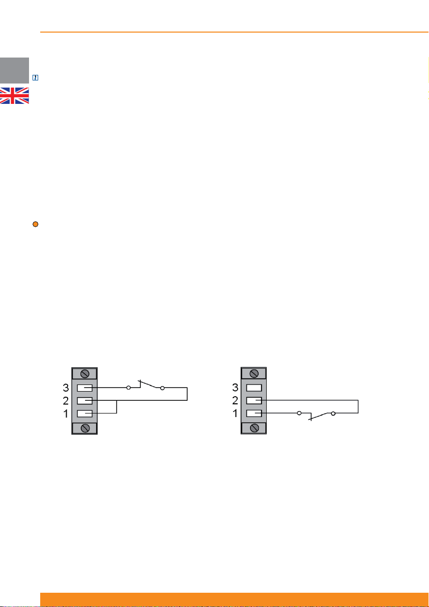
The external connection to the RPO/ROO circuit is located on the rear side of the unit and is composed of
three connector pins, as shown in the next fi gures.
ROO RPO
The unit comes out of the factory with a wire which connects pins 1 and 2. For normal UPS operation, these
pins must be kept connected.
In order to use the Remote Power Off (RPO) functionality, please remove this wire and connect a normally
closed volt-free contact between pins 1 and 2. When this contact is open, the UPS will disconnect all loads
and shut down. To return to normal operation, disconnect the unit from AC mains power, close the contact
and re-start the unit following the procedure outlined in section 4.4.3.2.
In order to use the Remote On Off (ROO) functionality, please connect a wire between pins 1 and 2 (the
UPS comes out of the factory with that wire) and connect a normally closed volt-free contact between pins
2 and 3. When this contact is open, the UPS will disconnect all loads. After that, if the contact is closed the
unit will re-start and restore power to the connected loads.
For other details regarding ROO/RPO operation, please see section 4.1.6.
30
945044.066
Page 33
Chloride Active
5 Communication Interfaces
The UPS is equipped with a serial interface (RS232 and USB ports) and a communication interface slot.
These interfaces can be used for:
- Direct communication between UPS and workstation/server
- Integration of the UPS as client into a network with centralized monitoring via a ManageUPS SNMP
adapter in the interface slot
- Transfer of operational states to external alarm systems via volt-free contacts (with interface volt-free
contact card, available as accessory, in the interface slot).
The necessary communication software packages and interface cables and cards are either bundled with
the unit or available as accessories.
5.1 Serial Interface
Two serial interfaces are available: DB9 port (RS232) and USB port.
NOTE: both ports cannot be used at the same time.
5.2 DB9 port
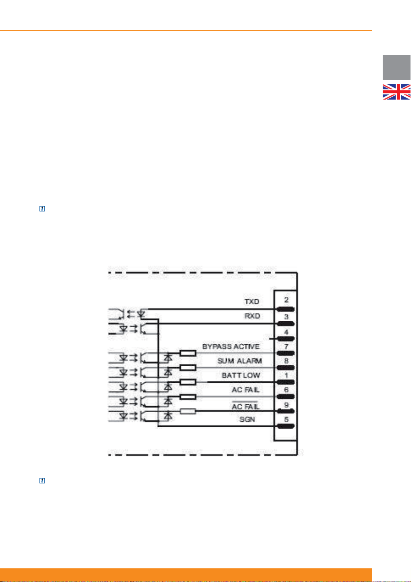
The 9-pole SUB-D connector (pin contacts) contains RS232 compatible signals.
UK
NOTE: this interface is electrically isolated from all other circuits.
Apart from the RS232 interface, fi ve opto-coupled alarm signals are available as open-collector outputs. Pin
distribution is as follows (see previous fi gure):
- SGN at pin 5: this connection point serves as a reference for all signals
- RxD at pin 3 and TxD at pin 2: correspond to the normal assignment of an RS232 interface
- BATTERY LOW at pin 1: this output is active when the battery capacity is below the pre-alarm level
31
Page 34

UK
Chloride Active
(please see section 4.2 for details on selection of this level) or when the remaining back-up time is less than
two minutes.
- AC FAIL (low-active at pin 9 and high-active at pin 6): this signal is active when the mains voltage at the
UPS input is not present for at least 10 seconds or the mains voltage exits the tolerance range. The signal
is cancelled 850ms following mains restoration.
- BYPASS ACTIVE at pin 7: This signal is active when the device has been switched to bypass, the inverter
is blocked and the power is supplied from the mains supply.
- SUM ALARM at pin 8: this output is low when one of the alarms “BATTERY LOW”, “AC FAIL” or “BYPASS
ACTIVE” is active.
5.3 USB port
As with the RS232 interface, the USB port facilitates the protocol-data transfer. The USB port included with
this UPS is classifi ed as HID (Human Interface Device).
5.4 Interface Slot
The interface slot can be fi tted with optional various cards. The connectors, designation and codes placed
in the slot will therefore depend on the type of interface card used. A detailed description is enclosed with
the interface cards which are available as accessories.
Interface cards available:
- SNMP adapter card (ManageUPS) for integrating the UPS into a network
- Volt-free contacts card
Please consult the available literature about these accessories or please ask your closest sales centre.
32
945044.066
Page 35

Chloride Active
6 Maintenance
6.1 Cleaning
Do not use scouring powder or plastic-dissolving solutions to clean the UPS.
Do not allow liquid to get inside the UPS.
Make sure that the air vents on the UPS are not obstructed. Remove dust from the air vents with a vacuum
cleaner.
Clean the outside of the UPS housing by wiping with a dry or slightly damp cloth.
6.2 UPS storage
For extended storage at ambient temperatures higher than 25ºC, the batteries should be charged for fi ve
hours once every four months. At higher storage temperatures it is advised that this period be reduced to
two months.
To charge batteries it is not necessary to unpack the unit. Simply connect the UPS to an appropriate power
source using the appropriate opening in the packaging and allow the batteries to charge for about fi ve
hours. After charging, note the date when recharging was performed on the UPS packaging.
6.3 Battery testing
The UPS does not require maintenance by the user; however, batteries should be checked periodically.
The UPS will automatically perform a battery self-test once a week. If a problem is discovered, the battery
fault LED will illuminate or the LCD Display will show an error message. See section 7 (“Troubleshooting”) if
a problem is found.
The frequency of testing can be changed via LCD Display or user software. Select battery self-test to be
performed monthly, weekly, daily or none.
UK
6.4 Battery replacement
ATTENTION: the load attached to the UPS will not be protected against loss of input power during this
procedure
6.4.1 Replacing the UPS internal batteries
For replacement of batteries locates in a service access area:
- Servicing of batteries should be performed or supervised by personnel knowledgeable about batteries and
the required precautions.
- When replacing batteries, replace with the same type and number of batteries or battery packs.- Do not
dispose of batteries in a fi re. The batteries may explode.
- Do not open or mutilate batteries. Released electrolyte is harmful to the skin and eyes. It may be toxic
- A battery can present a risk of electrical shock and high short-circuit current. The following precautions
should be observed when working on batteries:
Remove watches, rings, or other metal objects.
Use tools with insulated handles.
Wear rubber gloves and boots.
Do not lay tools or metal parts on top of batteries
Disconnect charging source prior to connecting or disconnecting battery terminals.
Determine if battery is inadvertently grounded. If inadvertently grounded, remove source from
ground. Contact with any part of a grounded battery can result in electrical shock. The likelihood of such
shock can be reduced if such grounds are removed during installation and maintenance (applicable to
33
Page 36
UK
Chloride Active
equipment and remote battery supplies not having a grounded supply circuit).
The UPS does not require maintenance by the user; however, battery maintenance is recommended
in accordance with IEEE Recommended Practice for Maintenance, Testing and Replacement of ValveRegulated Lead-Acid (VRLA) batteries for Stationary Applications (IEEE Std 1188-1996). When the
batteries expire, trained battery service personnel must replace them. A certifi ed disposal/recycling
company should carry out disposal/recycling of the UPS and/or batteries. Exhausted rechargeable batteries
are classifi ed as “harmful toxic waste” and as such the law demands that they be disposed of/recycled by
an authorized recycling center.
The manufacturer’s service center is fully equipped to deal with such batteries, in accordance with the law
and with the greatest respect for the environment. Contact your customer service representative to arrange
for maintenance and/or battery replacement.
The typical battery life cycle is 3 to 5 years, at an ambient temperature of 25ºC. However, battery life is also
dependant on the frequency and duration of mains failures or battery discharge cycles.
The BATTERY TEST (see section 6.3 “Battery Testing”) should be carried out periodically (6 to 12 months)
in order to ascertain the general conditions of the batteries.
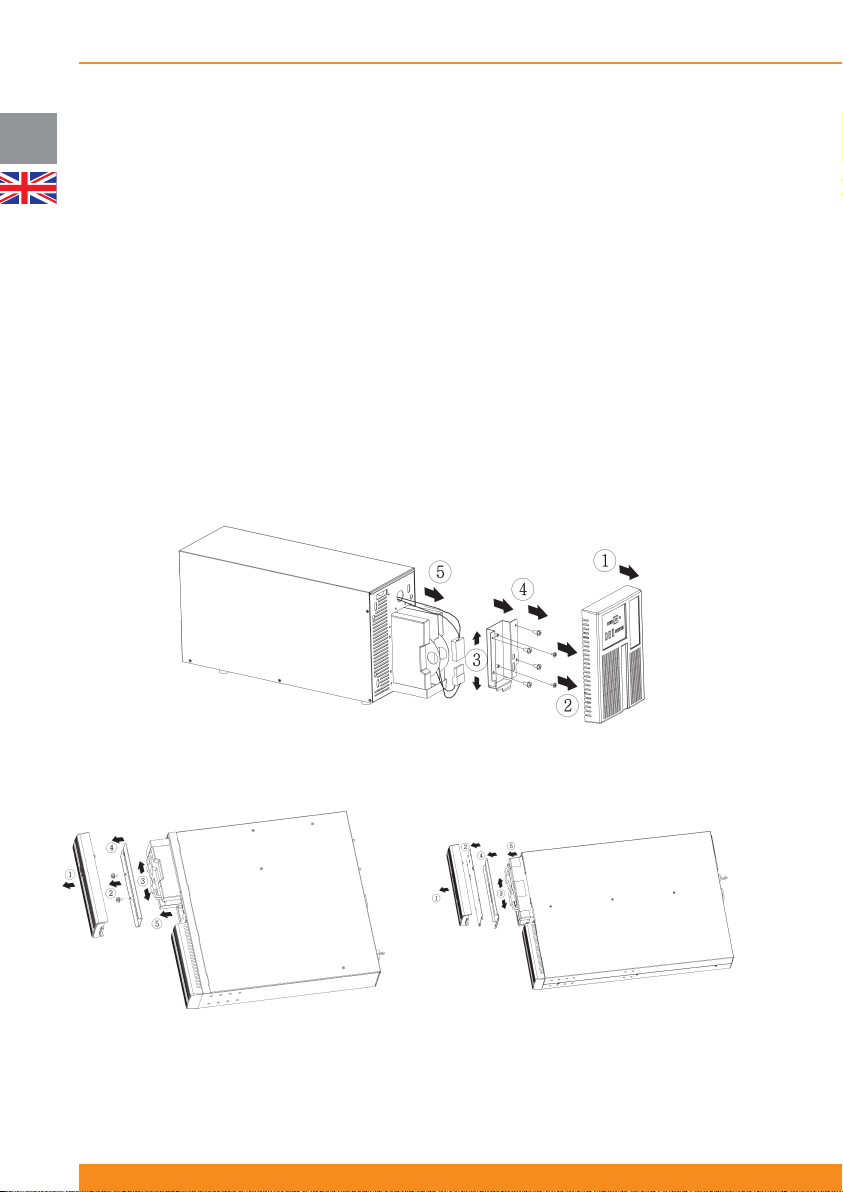
To replace internal batteries, place the UPS manually in bypass mode (see “Forced Bypass Procedure” on
section 4.4.4) and follow the steps illustrated in the next fi gures:
34
945044.066
Tower models
1/1.5kVA rack/tower models 2/3kVA rack/tower models
Page 37
Chloride Active
6.4.2 Battery disposal
The typical battery life cycle is 3 to 5 years, at an ambient temperature of 25ºC, but is also dependant on
the frequency and duration of mains failures.
Once the battery has reached the end of its useful life, follow the procedure for battery replacement (section
6.4.1).
After the batteries are replaced, a certifi ed disposal/recycling company should carry out disposal/recycling
of the used batteries.
Exhausted rechargeable batteries are classifi ed as “harmful toxic waste” and as such the law demands that
they be disposed of /recycled by an authorized recycling center.
The manufacturer’s service center is fully equipped to deal with such batteries, in accordance with the law
and with the greatest respect for the environment. Contact your customer service representative to arrange
for maintenance and/or battery replacement.
6.5 Front Panel with LCD Display Installation
WARNING: Installation must be carried out only by qualifi ed technicians.
Depending on your local market, the UPS can include a front panel based on LED indicators or a front
panel with a LCD Display. For units which include a front panel based on LED indicators as standard, front
panels with LCD display are available as accessory. These front panels have to be ordered separately.
UK
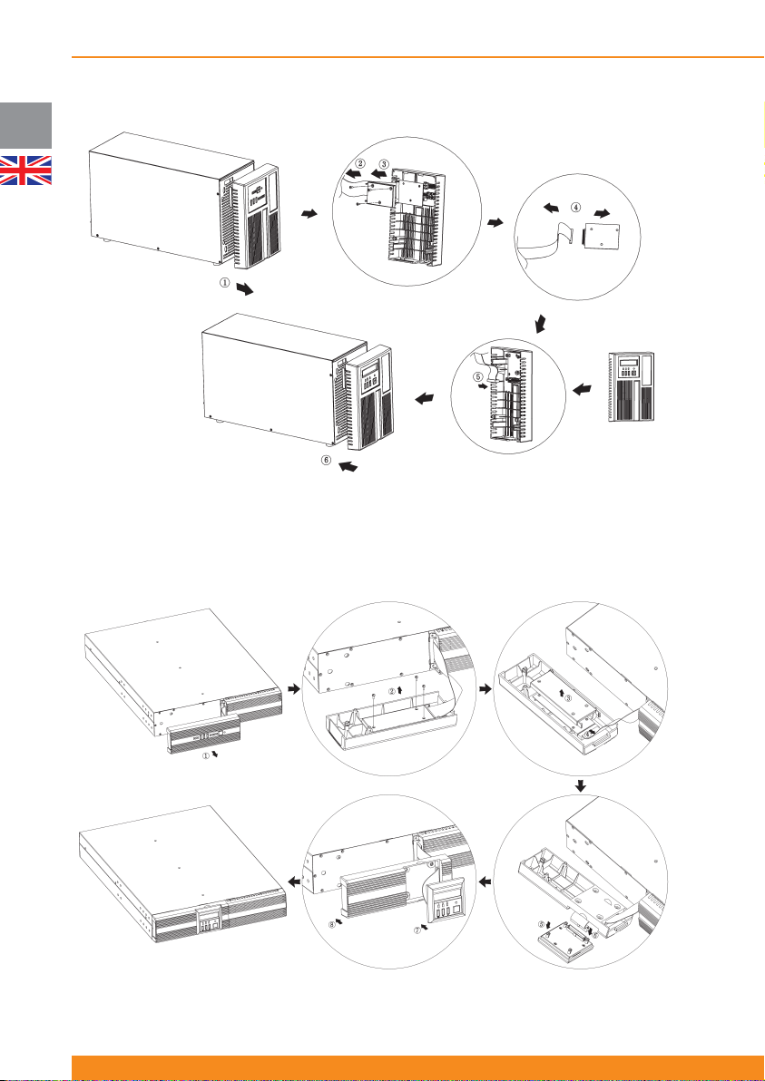
In order to replace the front panel with LED indicators with the front panel with LCD display, the following
steps (illustrated in the next fi gures) have to be followed:
WARNING: Before performing this installation, ensure that the inverter is switched off and the input power
cord is disconnected. Wait until all LEDs turn off (this may take around 1 minute after disconnection of the
UPS) prior to performing this installation.
1) Pull out the front panel with LED indicators
2) Unscrew the box containing the LED indicators from the front panel
3) Remove the box
4) Disconnect the fl at cable from the box (please pay attention to the position of the cable)
Tower units Rack/Tower units
5) Take the new front panel with the LCD Display
and connect the fl at cable to the box with the LCD
Display (the cable must be in the same position as
in the old front panel)
6) Insert the new front panel in the UPS
5) Take the new front panel with the LCD Display and
pull out the box containing the LCD Display
6) Connect the fl at cable to the box with the LCD
Display (the cable must be in the same position as
in the old front panel)
7) Insert the box with the LCD Display in the front
panel
8) Insert the new front panel in the UPS
35
Page 38
UK
Chloride Active
Tower models
Rack/Tower models
36
945044.066
Page 39
Chloride Active
7 Troubleshooting
If, in spite of the high reliability of this unit, problems should occur, please check the following points before
contacting the responsible customer service representative:
- Is the mains voltage present at the UPS input?
- Is the input fuse defective or have circuit breakers tripped?
If you contact the responsible customer service representative, please have the following information ready:
- Unit information (model, product code/MLBF, serial number as per nameplate)
- An exact description of the problem (what loads are being operated, does the problem occur regularly or
sporadically, etc)
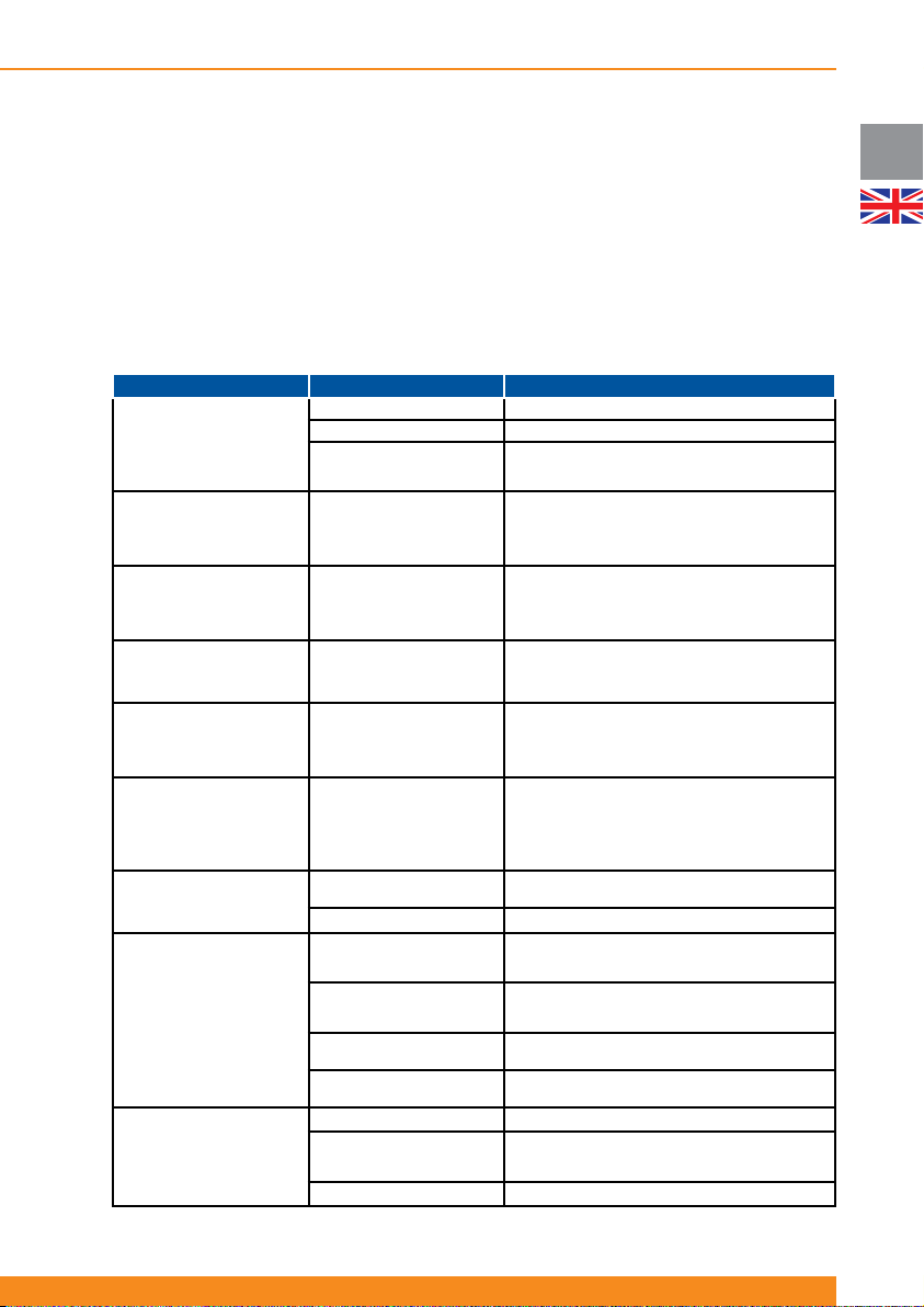
For description of the indicators mentioned below, please see chapter 4.2.
Problem Possible Cause Corrective Actions
No indication
No alarm
(UPS switched off)
UPS Overload LED blinks/
buzzer beeps at intervals (or
LCD Display shows overload
message)
UPS in bypass
UPS Overload LED blinks/
buzzer beeps continuously
(or LCD Display shows
overload message)
Load is dropped
Battery Fault LED blinks/
buzzer beeps at intervals (or
LCD Display shows battery
fault message)
Battery Fault LED blinks/
buzzer sound long beep
about once every hour
Site Wiring Fault Detection
LED blinks, Site Wiring Fault
E/D LED is ON, buzzer
sounds continuously (or LCD
Display shows Site Wiring
Fault message)
UPS Fault LED illuminates,
buzzer beeps continuously
(or LCD Display shows fault
message)
Autonomy less than specifi ed
No communication between
UPS and PC
Mains switch switched off Switch on mains switch
No mains voltage present Have mains inspected by qualifi ed electrician
Input fuse blown or input
circuit breaker tripped
Overload warning: UPS is
overloaded
(Unit on Line Mode)
Overload fault: UPS is
overloaded
(Unit on Battery Mode)
A battery fault was detected
during the automatic battery
neutral) has been detected
The fuse switch of the battery
extensions is in the “OPEN”
Charging device is defective
Wrong serial connection cable Check whether the correct cable has been used
Interface on the PC is being
used by another process or
Interference on the data cable Lay cable differently/Re-install cabling
test
The battery is at end of
life, runtime on battery is
compromised
Phase reversal (line and
on input power
UPS error
Overheating Decrease ambient temperature
position
Batteries are not fully
charged
Batteries are defective
is defective
Replace with fuse of same type or switch on
circuit breaker. If the problem persists, contact the
responsible customer service representative
Check the power drawn by the equipment and
disconnect any short-circuited or non-priority devices
Check the power drawn by the equipment and
disconnect any short-circuited or non-priority devices
Check that battery connector is properly seated
Reset alarm by pressing buttons 5 and 6 for 3
Reset the alarm by pressing ESC button for 3
Pull out mains plug and plug back in correctly
Contact the responsible customer service
Move the fuse switch to the “ON” position
Charge batteries and test backup time. If the
problem persists, contact the responsible customer
Contact the responsible customer service
Contact the responsible customer service
Check whether other software/service is accessing
the interface on the PC; try selecting a different
Re-start the UPS
Replace the battery module
seconds (units with LED indicators)
seconds (units with LCD Display)
Replace the battery module
representative
service representative
representative
representative
serial interface
UK
37
Page 40
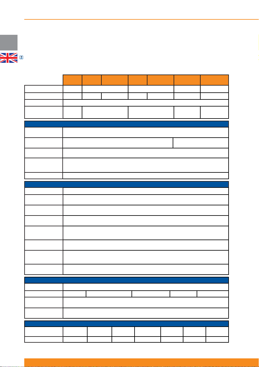
Chloride Active
UK
8 Specifi cation and back-up times
8.1 Specifi cation
NOTE: We reserve the right to modify the information in these tables without prior notice.
8.1.1 Uninterruptible Power Supplies
Active
UPS Rating 700VA 1000VA 1500VA 2000VA 3000VA
Housing Tower Tower Rack/Tower Tower
Technology Advanced on-line double conversion
Output Power
(VA/W)
Nominal input
voltage (VAC)
Operative input
voltage range (VAC)
Nominal input
frequency (Hz)
Operative input
frequency range
(Hz)
Input power factor 0,99 (batteries charged)
Waveform
Nominal output
voltage (VAC)
Voltage regulation
(%)
Output frequency
(Hz)
Harmonic distortion
(linear/non-linear
load) THDv
Transfer time (line-
battery-line) (s)
Overload capacity
(line mode, output
power factor 0.9)
Shortcircuit
protection
Type
Arrangement
Advanced Battery
Care
Battery
management
Size (WxHxD, mm)
Weight (kg) 13 15 18 18
700/630
1x2x7,2Ah
157x245x438 157x245x438
38
Active
700 T
1000 T
120V-284V (depending on output load)
200(**) / 208(**) / 220 / 230(default) / 240 V (confi gurable via user software and optional LCD
50/60Hz ±0,5% (same as input or selectable in Frequency Converter Mode)
<110% warning // 111-130%: 12 seconds (UPS to bypass) // >130%: 1,5 seconds (UPS off)
Battery pack auto detection, automatic runtime calculation, protection against deep discharge
Active
1000 RT
1000/900(*) 1500/1350(*)
50/60Hz +/-5% (40/70Hz if Frequency Converter Mode is activated)
Sealed maintenance-free lead acid (VRLA)
1x3x7,2Ah 1x3x9Ah
Active
1500 T
Rack/Tower Rack/Tower Rack/Tower
INPUT
200-240V
50/60Hz auto-selection
OUTPUT
Pure sinusoidal
Display) (250 V under request)
3%
Max. 4% / Max. 8%
0
Yes
BATTERIES
Yes
MECHANICAL
438x86
(2U)x482
157x245x488
Active
1500 RT
Active
2000 RT
2000/1800(*)
140-284V (depending on
output load)
1x6x7,2Ah 1x6x9Ah
438x86
(2U)x482
20
438x86
(2U)x657
26 31
Active
3000 RT
3000/2700(*)
438x86
(2U)x657
945044.066
Page 41
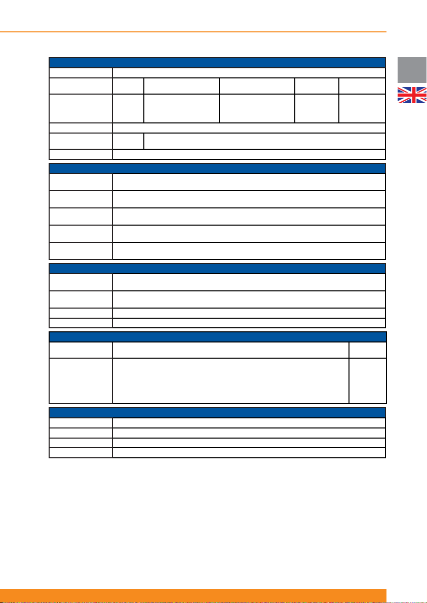
Chloride Active
Bypass
Effi ciency in line
mode (%)
Maximum Acoustic
Noise in on-line
mode at 1 meter
(dB)
Variable fan speed
External battery
packs
Color
Communication
Ports
Communication
Slot
Remote Power Off
(RPO)
Remote On/Off
(ROO)
Status signals
Operating
temperature
Storage
temperature
Altitude 0-3000m
Relative humidity 10% to 90%
Input
Output 6 x IEC320 C13 (10A), 3 of them controllable (2 groups)
CE Mark Yes
Safety EN 62040-1, EN 60950 (RD), TÜV, CB report, UL/cUL
EMC IEC62040-2, class C2; IEC61000-4-3/3/4/5/6/8/11; VDE160; IEC61000-2-2
Performance EN62040-3
86% 86% 86%
40
No
1xslot for SNMP/TCP-IP/Web interface or volt-free contacts card accessory
Opto-coupled, open-collector signals available at DB9 port: Battery Low, AC Fail, Bypass Active,
-25 ºC / +50 ºC without batteries, -15ºC / +40ºC with batteries
GENERAL
Yes (automatic)
41 41 47 47
Yes
Yes
Grey Anthracite (RAL7016)
CONNECTIVITY
1xDB9 (RS232 signals and status signals), 1xUSB (***)
Yes
Yes
SUM Alarm
ENVIRONMENTAL
0 - 40 ºC
CONNECTIONS
1 x IEC320 C14 (10A)
NORMATIVES
88% 90%
1 x IEC320
C20 (16A)
6 x IEC320
C13 (10A),
3 of them
controllable
(2 groups)
1 x IEC320
C19 (16A)
UK
(*)Output power with external battery packs is – 1000VA models: 1000VA/800W, 1500VA models:
1500VA/1200W, 2000VA models: 2000VA/1600W, 3000VA models: 3000VA/2400W.
(**) For output nominal voltage 200V, there is a power de-rating of 20% (the unit’s nominal power is
reduced by 20%). For output nominal voltage 208V, there is a power de-rating of 10% (the unit’s nominal
power is reduced by 10%).
(***) Both ports cannot be used simultaneously.
39
Page 42
UK
Chloride Active
8.1.2 Battery Packs
BP-A1000/1500-T BP-A1000/1500-RT BP-A2000/3000-RT
Housing
Battery arrangement
Protection
Tow e r
2x3x7,2Ah
Breaker 70A/80Vdc
MECHANICAL
Size (WxHxD, mm)
Weight (kg)
157x245x438
20
ENVIRONMENTAL
Operating temperature 0 - 40 ºC
Storage temperature -15 ºC / +40 ºC
Altitude 0-3000m
Relative humidity 10% to 90%
8.2 Runtime charts
Theoretical values with fully charged batteries and resistive load.
NOTE: The maximum quantity of external battery packs that can be connected to the UPS is four.
Active 700 T:
Load UPS
55W 51 min.
110W 35 min.
170W 24 min.
225W 18 min.
280W 15 min.
335W 12 min.
390W 10 min.
450W 8 min.
505W 7 min.
560W 5 min.
Rack/Tower Rack/Tower
2x3x7,2Ah 2x6x9Ah
Breaker 70A/80Vdc Breaker 70A/80Vdc
438x86(2U)x438 438x86(2U)x657
32 52
Active 1000 T and Active 1000 RT:
Load UPS
80W 63 min 239 min 438 min 661 min 861 min
160W 37 min 158 min 254 min 397 min 476 min
240W 26 min 91 min 197 min 262 min 372 min
320W 20 min 69 min 145 min 212 min 263 min
400W 15 min 55 min 97 min 174 min 220 min
480W 13 min 45 min 80 min 136 min 191 min
560W 11 min 38 min 69 min 99 min 161 min
640W
720W 7 min 29 min 51 min 75 min 99 min
800W 6 min 25 min 46 min 67 min 89 min
40
945044.066
UPS
+ 1 BP
9 min 33 min 60 min 86 min 130 min
UPS
+ 2 BP
UPS
+ 3 BP
UPS
+ 4 BP
Page 43
Active 1500 T and Active 1500RT:
Load UPS
120W 42 min 170 min 268 min 409 min 497 min
240W 25 min 84 min 180 min 234 min 331 min
360W 17 min 58 min 108 min 183 min 225 min
480W 13 min 44 min 78 min 129 min 183 min
600W 10 min 34 min 62 min 90 min 140 min
720W 8 min 26 min 51 min 74 min 98 min
840W 7 min 24 min 43 min 63 min 83 min
960W
1080W 4 min 18 min 32 min 48 min 64 min
1200W 3 min 16 min 28 min 42min 56 min
Active 2000 RT:
UPS
+ 1 BP
5 min 21 min 37 min 55 min 72 min
UPS
+ 2 BP
UPS
+ 3 BP
UPS
+ 4 BP
Chloride Active
UK
Active 3000 RT:
Load UPS
160W 63 min 231 min 406 min 558 min 754 min
320W 37 min 163 min 236 min 358 min 445 min
480W 26 min 97 min 195 min 237 min 327 min
640W 19 min 73 min 153 min 207 min 237 min
800W 15 min 58 min 108 min 177 min 213 min
960W 13 min 48 min 86 min 146 min 190 min
1120W 11 min 40 min 73 min 114 min 166 min
1280W
1440W 7 min 30 min 55 min 81 min 116 min
1600W 6 min 27 min 49 min 71 min 96 min
Load UPS
240W 42 min 173 min 238 min 371 min 456 min
480W 26 min 90 min 182 min 226 min 282 min
720W 18 min 62 min 123 min 185 min 218 min
960W 14 min 47 min 84 min 141 min 185 min
1200W 11 min 37 min 66 min 98 min 150 min
1440W 8 min 31 min 55 min 80 min 115 min
1680W 7 min 26 min 47 min 68 min 92 min
1920W
2160W 4 min 20 min 35 min 52 min 68 min
2400W 3 min 18 min 31 min 46 min 60 min
9 min 35 min 63 min 93 min 142 min
5 min 23 min 40 min 59 min 78 min
UPS
+ 1 BP
UPS
+ 1 BP
UPS
+ 2 BP
UPS
+ 2 BP
UPS
+ 3 BP
UPS
+ 3 BP
UPS
+ 4 BP
UPS
+ 4 BP
41
Page 44

Chloride Active
DE
1. Sicherheit
1.1 Bestimmungsgemäße Verwendung
1.2 Allgemeine Warnungen
1.3 Sicherheitshinweise
1.4 Batterie-Sicherheit
1.5 Umweltbezogene Anmerkungen
1.6 Anmerkung zur EU-Konformitätserklärung
1.7 Verpackung
2. Über dieses Handbuch
2.1 Einführung
2.2 Geräte-Übersicht
2.3 Symbole
2.4 Dokumentationsstruktur
3. Setup und Installation
3.1 Lieferung
3.2 Auspacken
3.3 Lieferumfang
3.3.1 Tower -Geräte (USV)
3.3.2 Tower -Geräte (Batteriepakete)
3.3.3 Rack/Tower -Geräte (USV)
3.3.4 Rack/Tower -Geräte (Batteriepakete)
3.4 Lagerung
3.5 Handhabung
3.6 Umgebungsbedingungen
3.7 Boden-Belastung
3.8 Belastung des Racks
3.9 Lüfterkühlung
3.10 Installationsdaten
3.11 Rack-Montage für USV bzw. Batterieschrank (nur RT-Modelle)
3.12 Boden-Montage für USV bzw. Batterieschrank für externe Batterien (Nur RT-Modelle)
3.12.1 Montage der USV (alleine)
3.12.2 Montage der USV plus externer Batterie
4. Betrieb und Inbetriebnahme
4.1 Theoretischer Hintergrund
4.1.1 Netzbetrieb
4.1.2 Batteriebetrieb
4.1.3 Bypass-Betrieb
4.1.4 ECO-Modus
4.1.5 Frequenzkonverter-Modus
4.1.6 Andere Betriebsdetails
4.1.7 Blockdiagramm
4.2 Display und Gerätelemente-Beschreibung
4.2.1 Geräte mit LED-Indikatoren
4.2.1.1 Beschreibung der Elemente
4.2.1.2 Betrieb
4.2.1.3Indikatoren
4.2.2 Einheiten mit LCD-Display
4.2.2.1 Menüs und Funktionen
4.2.2.2 Warnmeldungen und Fehleranzeigen
4.3 Rückseite
4.3.1Tower-Geräte
42
44
44
44
44
45
46
46
46
47
47
47
48
48
49
49
49
49
49
49
49
50
50
50
50
51
51
51
51
51
53
53
53
54
54
54
54
54
54
54
55
55
56
56
56
57
58
59
60
62
62
62
945044.066
Page 45

Chloride Active
4.3.2 Rack/Tower-Geräte
4.4 Inbetriebnahme und Abschalten
4.4.1 Elektrische Vorbereitungsarbeiten
4.4.2 Anschlüsse
4.4.2.1 Anschluss externer Batteriepakete
4.4.2.1 Anschluss an das Versorgungsnetz
4.4.3 USV-Inbetriebnahme
4.4.3.1 USV-Erstinbetriebnahme
4.4.3.2 Normale USV-Inbetriebnahme
4.4.4 Interner Bypass
4.4.5 ECO-Modus Aktivierung/Deaktivierung
4.4.6 Frequenzkonverter-Modus aktivieren
4.4.7 USV abschalten
4.4.8 Remote Power Off (RPO) / Remote On Off (ROO)
5. 5.Kommunikationschnittstellen
5.1 Serielle Schnittstelle
5.2 DB9 Port
5.3 USB Port
5.4 Schnittstellensteckplatz
6. Wartung
6.1 Reinigung
6.2 USV-Lagerung
6.3 Batterietest
6.4 Batterietausch
6.4.1 Die internen Batterien der USV austauschen
6.4.2 Entsorgen der Batterie
6.5 Installation Frontblende mit LCD Anzeige
7. Fehlerbehebung
64
65
DE
65
65
65
66
66
66
67
67
67
68
68
68
69
69
69
70
70
71
71
71
71
71
71
73
73
75
8. Technische Spezifi kationen und Laufzeit-Diagramme
8.1 Spezifi kationen
8.1.1 USV-Geräte
8.1.2 Batteriepakete
8.2 Laufzeit-Diagramme
76
76
76
78
78
43
Page 46

Chloride Active
DE
1. Sicherheit
1.1 Bestimmungsgemässe Verwendung
Die beschriebene Gerätreihe dient als unterbrechungsfreie Stromversorgung (USV) für angeschlossene
elektrische Lasten. Die Reihe entspricht den derzeitig gültigen Sicherheitsbestimmungen für Informationstechnik
und ist für den IT-Einsatz geeignet.
Abhängig von Art und Leistung der USV lassen sich bestimmte USV und Batterie-Kombinationen konfi gurieren.
Die optionalen Batteriepacks dürfen nur an eine kompatible USV-Basiseinheit angeschlossen werden.
1.2 Allgemeine Warnungen
WARNUNG: Persönliche Sicherheit wird bei Chloride groß geschrieben.. Daher ist es wichtig, dass alle
in diesem Manual behandelten sicherheitsrelevanten Vorgehensweisen und Schritte vor dem Aufbau des
Gerätes, aufmerksam gelesen und beachtet werden. Das Handbuch sollte griffbereit aufbewahrt werden.
Werden die Anweisungen von Abschnitt 3 (“Setup und Installation”) befolgt, können Benutzer jederzeit in den
USV-Betrieb eingreifen.
WARNUNG: Selbst wenn alle Schalter und/oder Schutzschalter ausgeschaltet sind, kann das Gerät noch Strom
führen. Es gibt keine Teile im Gerät, die gewartet werden müssen. Nur vom Hersteller authorisiertes Personal
darf Arbeiten vornehmen, die es z.B. erforderlich machen, Schutzabdeckungen zu öffnen oder zu entfernen.
Hinweis: Selbsttätig durchgeführte Reparaturen oder Änderungen können zum Erlöschen der Garantie führen.
Daraus bedingte Reparaturen werden ggfs. in Rechnung gestellt. Jeder nichtfachmännische Eingriff kann zu
Vorschriftsverletzungen führen und die Sicherheit des Gerätes beeinträchtigen.
WARNUNG: Um den UL Anforderungen zu entsprechen, muss eine Abschaltmöglichkeit am Ausgang der USV
vorhanden sein (Anmerkung: Der Ausgangsstecker kann als Abschaltmöglichkeit angesehen werden).
WARNUNG: Um den UL Anforderungen zu entsprechen schliessen Sie, um ein Feuerrisiko zu verringern,
die USV nur an einen Stromkreis an, der mit einer strombegrenzenden Sicherung von 20A ausgestattet ist,
entsprechend des National Electric Code, ANSI/NFPA 70)
1.3 Sicherheitshinweise
WARNUNG: Lesen Sie die nfl gd. Sicherheitshinweise aufmerksam durch! Die Nichtbeachtung der Hinweise
kann Ihr Leben, Ihre Gesundheit, die Zuverlässigkeit Ihrer USV und den Schutz Ihrer Daten gefährden.
- Transportieren Sie die USV nur in stoßsicherer Verpackung .
- Wird das Gerät von einer kühleren an eine wärmere Umgebung bewegt, kann sich Kondenswasser bilden.
Bevor Sie das Gerät einschalten, muss es vollkommen trocken sein. Dazu ist ein Akklimatisierungs-Zeitraum
von mindestens zwei Stunden erforderlich.
- Die USV muss entsprechend ihrer Umgebungsbedingungen - in Abschnitt 3.6 und 3.10 beschrieben installiert werden.
- Selbst wenn alle Schalter auf “OFF”/AUS stehen, ist die USV nicht vom Versorgungsstrom isoliert. Um sie
vollkommen zu isolieren, muss das Netzkabel aus der Steckdose gezogen werden.
- Das Gerät kann von mehreren Quellen gespeist werden.. An den Ausgangssteckern und/oder Buchsen
kann Spannung anliegen, selbst wenn die Netzversorgung getrennt ist. USV-Geräte stellen andere
Sicherheitsanforderungen als die meisten anderen elektrischen Geräte, da diese nach Ausfall des
Versorgungsnetzes in den Batterie-Betrieb wechseln.
- Im Falle einer Unterbrechung des Versorgungsnetzes hält die integrierte Batterie die Stromzufuhr zum
angeschlossenen Equipment aufrecht.
- Verlegen Sie alle Kabel vorschriftsgemäß, damit niemand auf diesen stehen oder über sie stolpern kann.
Beim Anschließen des USV-Systems an die Stromversorgung, ist den Anweisungen in Abschnitt 3 (“Setup
und Installation”) Folge zu leisten.
- Stellen Sie sicher, dass kein Fremdobjekt (Halskette, Büroklammern, etc.) in das Gerät gelangen kann.
- In Notfällen (wie etwa beschädigte Gehäuse, Steuer- oder Stromkabel, Eindringen von Flüssigkeiten oder anderer
Fremdkörpern) schalten Sie die Einheit aus und kontaktieren Sie den zuständigen Chloride-Kundendienst.
- Schließen Sie keine Geräte an die Einheit, die sie überlasten könnten oder Gleichstrom benötigen.
44
945044.066
Page 47

Chloride Active
- Soll die USV gereinigt werden, sind die Anweisungen in Abschnitt 6 (“Wartung”) zu befolgen.
- Datentransfer-Kabel sollten während eines Gewitters nicht verbunden oder abgeklemmt werden.
- Die Summe des Fehlstroms (Strom im Erdungskabel) der USV und der angeschlossenen Geräte darf nicht
3.5 mA überschreiten.
- Remote Power Off (RPO)- und Remote On Off (ROO)-Anschlüsse befi nden sich an der Geräte-Rückseite
(siehe dazu Abschnitt 4.4.8). Sind die entsprechenden Verbindungen geöffnet, schaltet der Schaltkreis sofort
die USV-Ausgangsbuchsen aus.
- Sind mehrere USV-Geräte in ein Rack integriert, sollte das schwere Equipment - wie USV und Batterien - in
Bodennähe und als erstes eingebaut werden.
- Das Gerät ist mit einem sicherheitsgeprüften Netzkabel ausgestattet und darf nur an Steckdosen mit
Erdungsanschluss angeschlossen werden.
- Stellen Sie sicher, dass die Buchse am Gerät oder der Anschluss des Erdungskontakts der Gehäuseinstallation
frei zugänglich ist.
1.4 Batterie-Sicherheit
WARNUNG: In den Batterien der USV und den Batteriepaketen befi ndet sich Akkumulatorsäure. Unter normalen
Bedingungen sind die Batterien trocken. Aus einer beschädigten Batterie kann Säure austreten, die in Kontakt
mit der Haut gefährlich ist und in den Augen Reizungen verursachen kann. Wenn dieser Fall eintreten sollte,
waschen Sie die betroffene Stelle ausgiebig mit Wasser und suchen Sie sofort einen Arzt auf.
- An den Batteriepolen liegt immer Spannung an.
- Selbst eine entladene Batterie hat die Kapazität, einen hohen Kurzschlussstrom zu erzeugen, was, neben
Schäden an Batterie und Kabel, beim Benutzer Verbrennungen verursachen kann.
- Batterien sollten nicht länger als 6 Monate (bei 25º C) gelagert werden, ohne zwischendurch aufgeladen zu
werden (Es muss sichergestellt sein, dass zu Beginn einer solchen Lagerzeit, die Batterien bereits zu 100%
geladen sind). Bei Nichtbeachten kann die Leistung der Batterie nachlassen. Es wird empfohlen, die Batterien
längstens alle 4 Monate aufzuladen.
- Da neue Batterien i.d.R. nicht gleich ihre volle Kapazität entfalten, empfi ehlt es sich, einige vollständige
Lade-/Entladezyklen durchzuführen, damit sich die volle Kapazität einstellt.
- Aus Umweltschutzgründen müssen Batterien entsprechend der Verordnungen für giftige Materialien
entsorgt/recycled werden.
Für das Ersetzen der Batterien in einer Zone mit Kundenservice:
- Arbeiten an den Batterien sollte von Personen überwacht oder durchgeführt werden, die Kenntnisse über
Batterien und die erforderlichen Vorsichtsmassnahmen haben
- Die Batterien der USV und der externen Batteriepaketen enthalten Akkumulatorsäure. Unter normalen
Bedingungen sind die Batterien trocken. Aus einer beschädigten Batterie kann Säure austreten, die in Kontakt
mit der Haut gefährlich ist und in den Augen Reizungen verursachen kann. Wenn dieser Fall eintreten sollte,
waschen Sie die betroffene Stelle ausgiebig mit Wasser und suchen Sie sofort einen Arzt auf.
- Wenn Sie die Batterien ersetzen, wählen Sie Batterien des gleichen Typs und der gleichen Anzahl Batterien
oder Batteriepaketen.
- Entsorgen Sie Batterien nie in einem Feuer. Die Batterien können explodieren.
- Öffnen oder beschädigen Sie nie das Batteriegehäuse. Ausgelaufene Batteriesäure ist für Haut und Augen
gefährlich und kann giftig sein.
- Eine Batterie kann einen elektrischen Schlag und einen hohen Kurzschlussstrom verursachen. Die folgenden
Vorsichtsmassnahmen sollten beachtet werden, wenn man mit Batterien arbeitet:
- Entfernen Sie Uhren, Ringe oder andere Metallobjekte
- Benutzen Sie Werkzeug mit isoliertem Griff
- Tragen Sie Gummihandschuhe und Schuhe mit Gummisohle
- Legen Sie keine Werkzeuge oder Metallteile oben auf die Batterien.
- Trennen Sie alle Ladequellen, bevor Sie die Batteriekontakte an- oder abklemmen.
- Prüfen Sie, ob die Batterie eine falsche Erdung hat. Wenn dem so ist, entfernen Sie die Quelle vom
Erdungsanschluss. Der Kontakt mit irgendeinem Teil einer geerdeten Batterie kann einen elektrischen
Schlag verursachen. Die Wahrscheinlichkeit eines solchen Schlags kann reduziert werden, indem solche
Erdungskontakte während der Installation und Wartung entfernt werden (anzuwenden bei Equipment und
Batterieversorgung, die keinen Versorgungsanschluss mit Erdung haben).
DE
45
Page 48

DE
Chloride Active
1.5 Umweltbezogene Anmerkungen
Diese USV enthält Batterien, deren Entsorgung nach gesetzlichen Vorschriften und Bestimmungen vorzunehmen
ist.
So sind die in Batterien enthaltenen Stoffe wie Blei und Säure - nach Ablauf der Batterielebensdauer umweltgerecht zu entsorgen.
Die Chloride bezieht schon in der Entwicklungsphase ihrer Produkte Entsorgungsaspekte mit ein, um
jedmögliche Umweltbeeinfl ussung so gering wie möglich zu halten. Umwelt verbessernde Technologien und
Verfahren begleiten deshalb, den gesamten Produktentstehungsprozess, um gefährliche Substanzen und
Rückstände zu reduzieren.
Dieses Handbuch enthält Empfehlungen, um die USV und ihre Komponenten optimal zu nutzen.
1.6 Anmerkung zur EU-Konformitätserklärung
Die Einheit entspricht folgenden europäischen Richtlinien:
73/23/EWG. Richtlinie des Rates zur Anpassung gesetzlicher Bestimmungen der Mitgliedsstaaten betreffend
elektrische Betriebsmittel zur Verwendung innerhalb bestimmter Spannungsgrenzen, geändert durch die
Richtlinie 93/68/EWG.
89/336/EWG. Richtlinie des Rates zur Anpassung gesetzlicher Bestimmungen der Mitgliedsstaaten betreffend
elektromagnetische Verträglichkeit, geändert durch die Richtlinien 91/263/EWG, 92/31/EWG und 93/68/
EWG.
Die Konformität wird durch Einhalten folgender Standards erreicht:
-EN 62040-1-1
-EN 62040-2
Zusätzliche Informationen bezüglich Einhalten dieser Richtlinien sind in den Anhängen NSR und EMC der
EU Konformitätserklärung zu fi nden.
Die Konformitätserklärung kann bei Chloride (QM) angefordert werden.
1.7 Verpacken der Einheit
Soll die USV veschickt werden, verpacken Sie diese frühestens zwei Stunden nach dem letzten
Ladevorgang.
Verpacken Sie das Gerät in Folie, die ausreichend luftdurchlässig ist (wie etwa bei 100μm Polyethylen).
Lassen Sie zwischen Gerät und Karton genügend Luftraum.
Soll die USV verschickt werden, tun Sie dies am besten mit der Original-Verpackung oder einem ähnlich
stabilen Karton.
46
945044.066
Page 49
Chloride Active
2 Allgemeines
2.1 Einführung
Dieses Handbuch enthält Informationen zu Installation, Betrieb und Einsatz der unterbrechungsfreien
Stromversorgung (USV).
Lesen Sie die Bedienungsanleitung, bevor Sie das Gerät installieren und bewahren Sie das Handbuch zum
Nachschlagen für Bedienungs- und Wartungsfragen griffbereit auf.
2.2 Geräte-Übersicht
Die Serie A wird mit verschiedenen Nennleistungen und Gehäusen -siehe nfl gd. Tabelle - geliefert..
Gehäuse Bezeichnung
Tower
(aufrecht stehende Einheit)
Rack/Tower konvertierbar
(kann eine aufrecht
stehende oder Rack-
Montage-Einheit sein)
Diese Geräte werden standardgemäß mit an der Frontblende angebrachtem LED-Display geliefert. Frontblenden
mit LCD-Anzeige sind als Zubehör für alle o.g. USV-Modelle erhältlich (müssen jedoch separat bestellt
werden!).
Die Montage der Frontblende mit LCD-Anzeige muss von einem qualifi zierten Techniker vorgenommen
werden. Bitte kontaktieren Sie den zuständigen Kundendienst. Für weitere Informationen zur Installation,
lesen Sie bitte Abschnitt 6.5.
Active 700 T 700 VA
Active 1000 T 1000 VA
Active 1500 T 1500 VA
Active 1000 RT 1000 VA
Active 1500 RT 1500 VA
Active 2000 RT 2000 VA
Active 3000 RT 3000 VA
Nennleistung
DE
Folgende Batteriepakete sind lieferbar:
Gehäuse Bezeichnung Kompatible USV Einheit
Tower
(aufrecht stehende Einheit) BP-A1000/1500 T
Rack/Tower konvertierbar
(kann eine aufrecht
stehende oder Rack
Montage Einheit sein)
BP-A1000/1500 RT
BP-A2000/3000 RT
Active 1000 T
Active 1500 T
Active 1000 RT
Active 1500 RT
Active 2000 RT
Active 3000 RT
47
Page 50

DE
Chloride Active
2.3 Symbole
ACHTUNG: Eine Anweisung, die bei Nichtbeachten die Zuverlässigkeit der USV oder der Daten gefährden
kann.
WARNUNG: Eine Anweisung, die bei Nichtbeachten, zu einem elektrischen Schlag führen kann, der Ihr Leben,
Ihre Gesundheit, die Zuverlässigkeit Ihrer USV oder die Sicherheit Ihrer Daten gefährden kann..
ANMERKUNG: Eine Anleitung oder Kommentar, der weitere Details zur USV beinhaltet bzw. ergänzt.
2.4 Struktur
Die Anweisungen können durch zusätzliche Blätter ergänzt werden, die z.B. spezifi sche Erweiterungen oder
Optionen beschreiben.
48
945044.066
Page 51
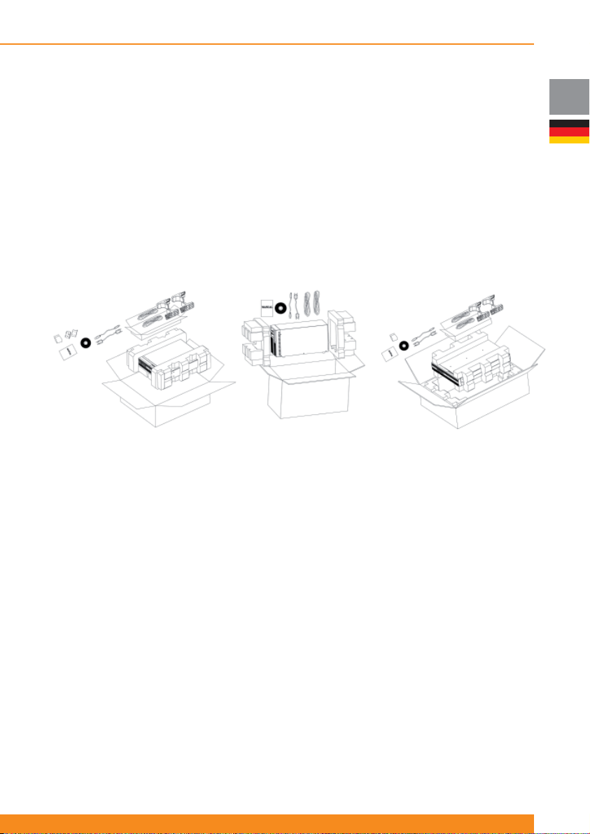
Chloride Active
3 Setup und Installation
3.1 Lieferung
Das vlgd. Gerät wurde vor Auslieferung fachmännisch kontrolliert. Nach Empfang, prüfen Sie Verpackung
und Inhalt. Schäden müssen dem Speditionsunternehmen, das Fehlen von Teilen, dem Hersteller unmittelbar
nach dem Feststellen mitgeteilt werden.
3.2 Auspacken
Bitte packen Sie das Gerät vorsichtig aus um Beschädigungen zu vermeiden. Prüfen Sie das Verpackungsmaterial
anschließend, ob Sie nicht versehentlich Kleinteile darin zurücklassen. Die unteren Graphiken dienen nur
zur Beschreibung; der Inhalt kann je nach Kaufort unterschiedlich ausfallen.
1 und 1,5 kVA Rack/Tower Einheiten
Tower Einheiten
3.3 Lieferumfang
In den nfl gd. Punkten ist der Lieferumfang beschrieben:
2 und 3 kVA Rack/Tower Einheiten
DE
3.3.1 Tower Einheiten (USV)
- 1 x Handbuch (Manual)
- 1 x USV-Gerät
- 1 x Kurzanleitung
- 1 x CD mit Anwender-Software
- 2 x Anschlusskabel IEC320 C14 (Stecker) - IEC320 C13 (Buchse) für USV Ausgang
- 1 x RS232 Schnittstellenkabel
- 1 x USB Schnittstellenkabe
3.3.2 Tower Einheiten (Batteriepakete)
- 1 x Batteriepaket
- 1 x Batterie-Verlängerungskabel
- 1 x Batteriepaket-Erkennungskabel (zur automatischen Erkennung der Anzahl der angeschlossenen
Batteriepakete)
3.3.3 Rack/Tower Einheiten (USV)
- 1 x Handbuch (Manual)
- 1 x USV-Einheit
- 1 x Kurzanleitung
- 1 x CD mit Anwender-Software
- Versorgungskabel wie folgt:
49
Page 52
Chloride Active
DE
1000, 1500 und 2000VA Modelle
2 x Anschlusskabel IEC320 C14
(Stecker) - IEC320 C13 (Buchse)
für USV Ausgang
- 1 x RS232 Schnittstellenkabel
- 1 x USB Schnittstellenkabel
- 2 x Frontrahmen für Rack-Montage und erforderliches Montagematerial
- 2 x Sätze Standfüße (für Boden-Aufstellung)
- 2 x Gleitschienen-Kits für Rack-Montage (optional) und erforderliches Montagematerial
3000VA Modelle
1 x Anschlusskabel Schuko
(Stecker) - IEC320 C19 (Buchse)
für USV Eingang
1 x Mehrfach-Steckdose
Verlängerung IEC320 C20
(Stecker) – 3 x Schuko (Buchse)
für USV Ausgang
3.3.4 Rack/Tower-Einheiten (Batteriepakete)
- 1 x Batteriepaket
- 1 x Batterie-Verlängerungskabel
- 1 x Batteriepaket-Erkennungskabel (zur automatischen Erkennung der Anzahl der angeschlossenen
Batteriepakete)
- 2 x Frontrahmen für Rack-Montage und erforderliches Montagematerial
- 2 x Scheiben für die Standfüße der Tower-Sets (zur Bodenbefestigung)
- 1 x Platte, um das Batteriepaket an der USV bei Bodenbefestigung zu sichern
- 2 x Gleitschienen-Kits für Rack-Montage (optional) und erforderliches Montagematerial
3.4 Lagerung
Wird die USV in den ersten sieben Tagen nach Lieferung nicht eingesetzt, sollten folgende
Lagervoraussetzungen beachtet werden:
Die USV sollte in einer sauberen, trockenen Umgebung und vor extremen Temperaturen geschützt
untergebracht werden (am besten in einem klimatisierten Raum mit geringer Luftfeuchtigkeit). Nfl gd.
Tabelle gibt die Temperatur- und Feuchtigkeitsbereiche für die Lagerung an:
Temperaturbereich
Relative Luftfeuchtigkeit
(nicht kondensierend)
-25ºC/50ºC (ohne Batterien)
-15ºC/40ºC (mit Batterien)
10-90%
3.5 Handhabung
Die USV darf nur in aufrechter Position gelagert und bewegt werden. Es können Schäden entstehen, wenn
das Gerät fallen gelassen oder starken Stößen ausgesetzt wird.
3.6 Umgebungsbedingungen
Die Tower-Version muss vertikal installiert werden. - Die USV Rack/Tower-Version (Kürzel „RT“ ) hingegen
kann sowohl vertikal als auch horizontalinstalliert werden (abhängig von der gewünschten Anordnung).
Die USV sollte auf einer fl achen, ebenen Oberfl äche installiert werden, in einem Bereich, der vor extremen
Temperaturen, vor Wasser, Feuchtigkeit und leitendem Pulver oder Staub geschützt ist (siehe Abschnitt
3.10). Stapeln Sie nicht mehrere USV-Einheiten übereinander und stellen Sie nichts auf die Geräte.
Der Betriebstemperaturbereich wird im Abschnitt 8 („Technische Spezifi kationen“) angegeben.
Die ideale Umgebungstemperatur liegt zwischen 15º C und 25º C.
Die erwartete Batterie-Laufzeit und Lebenszeit ist defi niert bei einer Umgebungstemperatur von 20º C. Bei
Temperaturen über 25º C verkürzt sich die Batterie-Lebenszeit.
50
945044.066
Page 53
Chloride Active
3.7 Belastung des Bodens
Aufgrund des Gewichts von USV und Batterieerweiterungen der Tower- und RT-Modelle (die als Tower
eingesetzt werden sollen) ist die Festigkeit des Bodens für das Tragen der Last wichtig.
ANMERKUNG: Gewichte von USV und Batteriepakete sind in Abschnitt 8 („Technische Spezifi kationen“)
aufgeführt.
3.8 Belastung des Racks
Aufgrund des Gewichts der USV und der Batterie(pakete) der RT-Modelle (die in einem Rack montiert
werden sollen) ist die entsprechende Stabilität des Schranks wichtig.
ANMERKUNG: Gewichte von USV und Batteriepakete sind in Abschnitt 8 („Technische Spezifi kationen“)
aufgeführt.
3.9 Luftkühlung
Für die Luftzirkulation sind mindestens 50 mm Freiraum (Abstand) an Vorder- und Rückseite der USV
einzuhalten.
Wartungs- und Reparaturarbeiten erfordern entsprechenden Zugang zu Vorder- und Rückseite der USV.
Stellen Sie dem Wartungspersonal deshalb den notwendigen Platz zu Verfügung.
3.10 Installationsdaten
Punkt Spezifi kation
Umgebungstemperatur 0ºC bis 40ºC
Relative Luftfeuchtigkeit (nicht kondensierend) 20%-90%
Umgebung Gesteuert (Büro oder ähnliche)
Max. Höhe (ohne Leistungsminderung) 3.000 meter
Netzanschluss Hinten
Ausgangsanschlüsse Hinten
Batterieanschlüsse Hinten
Lufteinlass Vorne
Luftauslass Hinten
DE
3.11 Rack-Montage der USV bzw. des Batteriepacks (nur RT- Modelle)
Rack/Tower -Geräte und externen Batteriepacks können in den Standard-19“-Rahmen montiert werden.
Für USV und Batteriepacks wird das gleiche Montagematerial benutzt; der Montage-Vorgang ist bei Beiden
gleich.
ACHTUNG: Die USV zieht von der Vorderseite Kühlluft. Besitzt der Schrank eine Tür , stellen Sie sicher,
dass genügend Abstand zwischen Lüfter und Schranktür ist.
Aufgrund des Gewichts und der Gerätegröße (besonders der 2 und 3 kVA-Modelle) wird empfohlen, die
USVen stets durch zwei Personen anzuheben. Falls keine zweite Person zur Verfügung steht, ist es auch
möglich, die internen Batterien abzuklemmen und auszubauen, um die Rack-Montage ohne Batterien
vorzunehmen (weniger Gewicht) und diese im Anschluss daran einzubauen
51
Page 54
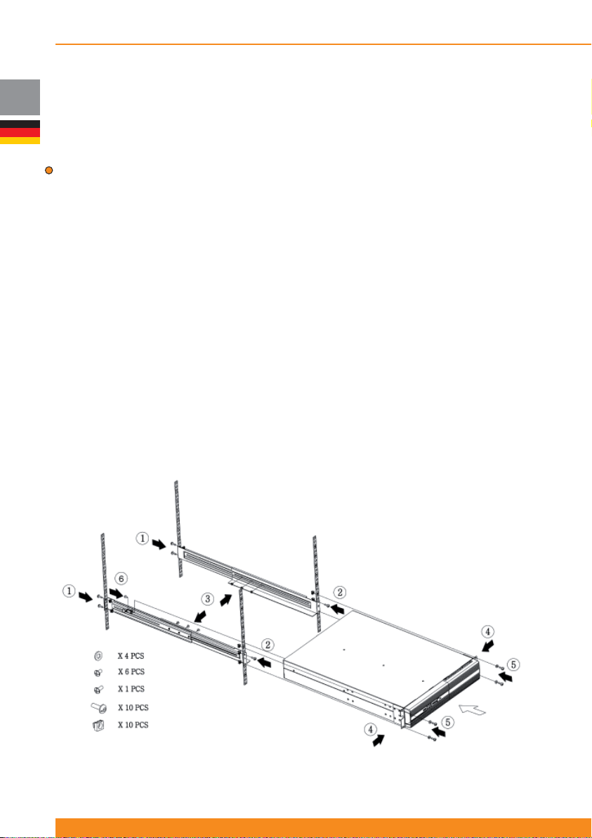
DE
Chloride Active
Bitte benutzen Sie das mitgelieferte Befestigungsmaterial, um die Montagerahmen an die USV oder die
Batteriepakete zu befestigen.
Werden externe Batteriepacks genutzt , montieren Sie diese zuerst und möglichst bodennah. Beginnen Sie
mit der tiefstmöglichen Position und montieren Sie dann weiter nach oben. Die USV wird dann als Letztes
(über den Batteriepacks) montiert, was die Verlegung der Kabel vereinfacht
ACHTUNG: Benutzen Sie das gesamte Befestigungsmaterial an jeder USV und den externen
Batteriepacks. Befestigen Sie NIEMALS andere Geräte an darunter liegenden Geräten.
Für die USV-Rack-Montage ist entsprechendes Zubehörmaterial verfügbar (verpackt oder optional
erhältlich). Um die USV und die externe Batterie im Rack unterzubringen, installieren Sie zunächst die
Gleitschienen (optionales Zubehör). Danach gehen Sie wie folgt vor:
1. Befestigen Sie die hinteren Schienenseiten mit zwei mitgelieferten Schrauben an die hintere
Schrankseite
2. Schrauben Sie die vorderen Schienenseiten mit zwei mitgelieferten Schrauben an die vordere
Schrankseite
3. Installieren Sie die Seitenschienen und sichern Sie jede Schiene mit drei Schrauben
4. Verbinden Sie an jede Seite der USV die vorderen Rahmenteile mit vier Schrauben an jeder Seite
5. Schieben Sie die USV in ihre Position im Schrank und sichern Sie diese mit zwei Schrauben an jeder
Seite
6. Verbinden Sie die Schiene an die hintere Seite der USV (Befestigungspunkt für sicheren Transport)
7. Wiederholen Sie die oben angegebenen Schritte für jede(s) zu montierende USV oder Batteriepaket.
Nachdem die Montage abgeschlossen ist, lesen Sie bitte Abschnitt 4 für die Inbetriebnahme des Systems
52
945044.066
Page 55
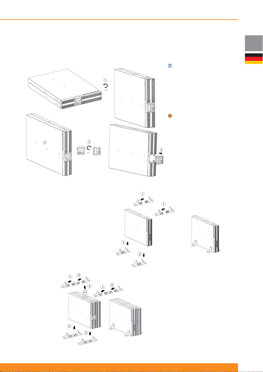
Chloride Active
3.12 Boden-Montage der USV bzw. des externen Batteriepacks (nur RT- Modelle)
Die „RT“-USV und externe Batteriepacks sind so ausgelegt, dass sie auch alternativ zur Schrankmontage
am Boden aufgestellt werden können.
ANMERKUNG: (nur für
Einheiten mit LCD-Anzeige
an der Vorderseite) Das LCDDisplay kann in entsprechende
Lage verdreht werden, wenn die
USV auf dem Boden aufgestellt
wird, wie in der nfl gd. Zeichnung
dargestellt.
ACHTUNG: Benutzen Sie das
gesamte Befestigungsmaterial
an jeder USV und den externen
Batteriepaketen.
Nachdem die mechanische
Montage abgeschlossen ist,
lesen Sie bitte Abschnitt 4 für die
Inbetriebnahme des Systems.
3.12.1 Montage der USV
DE
Bauen Sie die zwei Fußsätze,
die im Lieferumfang der USV
enthalten sind, und stellen Sie
die USV „“in“ die Füße, wie auf
der nfl gd. Zeichnung dargestellt
3.12.2 Montage der USV
plus einer externen
Batterie
Bauen Sie die zwei Fußsätze,
die im Lieferumfang der
USV enthalten sind, und
stellen Sie die USV „in“ die
Füße, wie auf der Zeichnung
dargestellt. Sichern Sie dann
USV und Batteriepakete mittels
beiliegender Platten und
Schrauben.
53
Page 56

Chloride Active
DE
4 Betrieb und Inbetriebnahme
4.1 Grundlegendes
ACHTUNG: Die USV ist mit Standard-Stromkabel und Steckdosen ausgestattet. Das Gerät kann auch von
Nicht-Technikern installiert und betrieben werden.
4.1.1 Netzbetrieb
Die USV ist nach der Installation mit dem Versorgungsnetz auf der einen Seite, und der Last auf der
anderen Seite verbunden. Der Betrieb basiert auf dem On-line- bzw. Doppelwandlerprinzip. Dabei wird der
Wechselstrom vom Eingang zunächst in Gleichstrom und dann wieder in Wechselstrom mit fester Frequenz
und Spannung umgewandelt . Diese USV-Topologie wird eingesetzt, um kritische Lasten vor Netzstörung
und Stromausfall zu sichern.
4.1.2 Batteriebetrieb
Kommt es zu einem Stromausfall versorgen die (wartungsfreien) Batterien die Last. In der Praxis sind
Stromausfälle von relativ kurzer Dauer. I.d.R. reicht daher die gespeicherte Energie der Batterien, um den
kontinuierlichen Betrieb der angeschlossenen Last aufrecht zu erhalten, bis das Versorgungsnetz wieder
verfügbar ist. Im Falle eines längeren Stromausfalls, aktiviert die USV- Software ein geregeltes Abschalten
(Shutdown) der Last.
Zur Feststellung der Batterie-Laufzeit dienen das LCD-Display , Betriebssoftware und SNMP-Netzwerk
Karte. Per Software wird die Batterie-Laufzeit vor und während eines Stromausfalls angezeigt. außerdem
ist es möglich, Abschaltprozeduren aufzurufen, welche die angeschlossenen Geräte nach dem sicheren
Schließen aller offenen Programme und des Betriebssystems die Geräte abschalten. Sobald das Netz
wieder verfügbar ist, versorgt die USV das angeschlossene Equipment mit Strom und beginnt, die Batterien
wieder aufzuladen.
4.1.3 Bypass-Betrieb
Bei Überlastung oder einem internen USV-Fehler, wird das angeschlossene Equipment sofort über das
Netz versorgt, durch Aktivierung des internen Bypass. Sobald der normale Zustand der USV wieder
hergestellt ist, schaltet die USV automatisch wieder auf den Konverterbetrieb um.
Alternativ kann der Benutzer über die Schalter an der vorderen Blende oder über das LCD-Display
den Bypass aktivieren. In einem solchen Fall schaltet sich die Einheit automatisch aus, wenn die
Eingangsparameter (Spannung, Frequenz) außerhalb des Toleranzbereiches liegen.
4.1.4 ECO-Modus
Wurde der ECO-Modus aktiviert und befi ndet sich das Versorgungsnetzes innerhalb der Toleranzen, wird
die angeschlossene Last direkt über den internen Bypass versorgt. Dabei werden hohe Wirkungsgradwerte
erreicht und Energie gespart. Wenn der ECO-Modus aktiviert ist und die Bedingungen des Netzes
außerhalb der Toleranzen liegen, versorgt die USV die Last über den Konverter, um die angeschlossenen
Geräte zu schützen.
Arbeitet die USV im ECO-Modus, ist der interne Batterielader aktiv. So werden die Batterien weiterhin
geladen, bzw. der Ladezustand gehalten.
Details dazu können Sie in Abschnitt 4.4.5 nachlesen.
4.1.5 Frequenzwandler-Modus
Diese USV kann als Frequenzwandler betrieben werden und 50 Hz oder 60 Hz (je nach Wahl) abgeben,
wenn die Eingangsfrequenz zwischen 40 und 70 Hz liegt.
Arbeitet die USV als Frequenzwandler, reduziert sich die Leistung auf 50 %. Dies bedeutet, dass in diesem
Modus nur 50 % der nominalen Leistung genutzt wird.
54
945044.066
Page 57
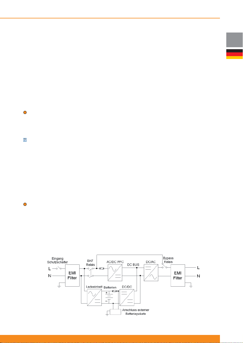
Chloride Active
Wird die USV als Frequenzwandler eingesetzt, kann weder der ECO-Modus noch der Bypass-Betrieb
aktiviert werden.
Details dazu können Sie in Abschnitt 4.4.6 nachlesen.
4.1.6 Weitere Betriebsdetails
Der nfl gd. Abschnitt beschreibt die weiteren Funktionen der USV. Betriebsdetails hierzu siehe Abschnitt 4.2,
4.3 und 4.4.
a) Green Power-Funktion: Im Batterie-Betrieb ohne Last am Ausgang schaltet sich die USV nach 5 Min.
automatisch ab, um Energie zu sparen.
b) Kaltstart: Ist diese Funktion aktiviert ist, startet die USV, auch wenn keine Spannung vom
Versorgungsnetz anliegt. Dabei werden die angeschlossenen Geräte direkt über die Batterien versorgt.
ACHTUNG: Wird die USV erstmalig eingeschaltet, muss Spannung vom Versorgungsnetz anliegen.
c) Auto-Restart: Ist diese Funktion aktiviert, startet die USV automatisch, nach der Abschaltung am Ende
der Batterie-Überbrückungszeit, wenn die Spannung des Versorgungsnetzes wieder anliegt (etwa nach
längerem Stromausfall). Andernfalls muss die USV manuell gestartet werden.
ANMERKUNG: Ist diese Funktion aktiviert und es kommt zu einem weiteren Stromausfall (nachdem die
USV automatisch gestartet wurde, ist die Überbrückungszeit kurz, da die Batterien noch nicht vollkommen
geladen sind.
d) Erkennen von Anschlussfehlern: Die USV erkennt, ob Eingangsphase und Neutralleiterverdreht wurden
als Fehler.
e) Batterietest: Die USV kann einen Batterietest manuell, durch den Benutzer gestartet, oder automatisch,
in einem festgelegten Zeitintervall durchführen.
f) Steuerbare Ausgänge: Die USV besitzt zwei Gruppen steuerbarer Ausgangsbuchsen (Buchse 1 und 2).
Jede Gruppe kann so konfi guriert werden, automatisch abzuschalten, wenn die Batterieleistung unter einen
bestimmten Wert fällt (75%, 50%, 25% oder 0%), oder manuell durch den Benutzer.
ACHTUNG: Es wird empfohlen, das Equipment mit höherer Priorität an die Hauptausgangsbuchsen und
die Geräte mit geringerer Priorität an die steuerbaren Ausgangsbuchse anzuschließen.
g) Remote Power Off (RPO) / Remote On Off (ROO): Schnittstelle an der Geräte-Rückseite, ermöglicht,
die USV per Fernzugrilff aus- und wieder einzuschalten (ROO) oder sie auszuschalten, ohne die Option,
wieder zu starten (RPO). Weitere Informationen dazu, siehe Abschnitt 4.4.8.
4.1.7 Blockdiagramm
DE
55
Page 58
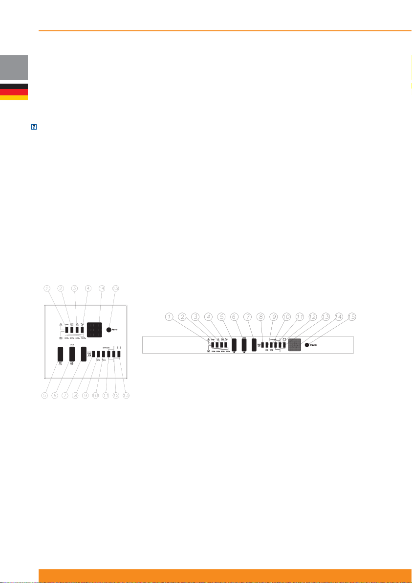
DE
Chloride Active
4.2 Display-Anzeigen und Beschreibung der Gerätelemente
4.2.1 Geräte mit LED-Anzeige
Tower und Rack/Tower Modelle können lokal verschieden mit LED-Anzeigen oder mit einem kombinierten
LCD-/LED-Display ausgestattet sein.
ANMERKUNG: Frontblenden nur mit LED Anzeige lassen sich durch ein als Zubehör bestellbares LCD-
Display umrüsten.. Für weitere Informationen dazu, sehen Sie bitte Abschnitt 4.2.2.
4.2.1.1 Beschreibung der Bedienelemente bei der LED-Anzeige
- Hauptschalter USV EIN / AUS und zugehörige LED
- Ein vereinfachtes Blockdiagramm der USV zeigt den augenblicklichen Betriebsmodus der USV an (wie
etwa Netzbetrieb, Batteriebetrieb, Bypassbetrieb)
- Zwei LEDs zeigen den augenblicklichen Status (AN oder AUS) der steuerbaren Ausgangsbuchsen 1 und
2 an.
- Vier zusätzliche LEDs geben den Fehlerstatus, die Last in Prozent oder den Batterie Ladezustand in
Prozent an, abhängig vom entsprechenden Schalterstatus an der Frontblende.
- Schalter und LED zur Erkennung von Anschlussfehlern
56
945044.066
1. LED Erkennung von Anschlussfehlern
2. LED Batteriefehler
3. LED USV Fehler
4. LED USV Überlast
5. Taste Anzeigeauswahl
6. LED Test/Alarm Rückstelltaste
7. Anschlussfehler A/D Taste
8. LED Anschlussfehler A/D
9. Ausgangsbuchse 1 EIN / AUS LED
10. Ausgangsbuchse 2 EIN / AUS LED
11. LED Bypass Modus
12. LED Netzmodus
13. LED Batterie-Betrieb
14. EIN/AUS Schalter
15. AN LED
Page 59
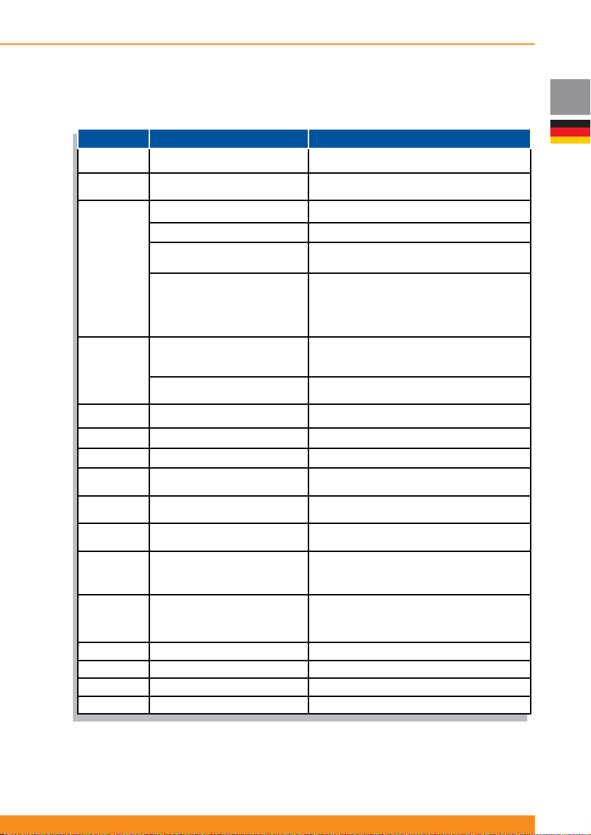
4.2.1.2 Betrieb
Taste/LED Funktion Betrieb/Defi nition
Taste 14
Taste 7 Anschlussfehler A/D Taste
Taste 6
EIN/AUS Schalter
Summer stumm (Alarm Reset)
LED Test Betätigen, um LEDs zu testen (alle LEDs blinken)
Einheit umschalten auf Bypass oder
zurück (forciert)
LCM Alarm Reset (Alarm, der Ende
der geschätzten Batterie Lebenszeit
angibt)
Eine Sekunde halten, um USV ein-/auszuschalten
Sieben Sekunden halten, um Erkennung von
Anschlussfehlern zu aktivieren/deaktivieren
Eine Sekunde halten, um den Summer stumm zu
Betätigen Sie Taste 6 und 5 für vier Sekunden, um die
Einheit auf Bypass oder wieder zurück zu schalten
Betätigen Sie Taste 6 und 5 für drei Sekunden, um den
Alarm zurückzustellen (wenn der Alarm aktiv ist, ist es
notwendig, diese Tasten weitere 4 zu halten, um die
Einheit in Bypass-Betrieb zu schalten, Funktion wie
oben angegeben)
Chloride Active
DE
schalten
(forciert)
Taste 5
LED 1 (*) LED Erkennung von Anschlussfehlern Zeigt an, ob ein Anschlussfehler erkannt wurde
LED 2 (*) LED Batteriefehler Zeigt an, ob ein Batteriefehler erkannt wurde
LED 3 (*) LED USV Fehler Zeigt an, ob ein USV Fehler erkannt wurde
LED 4 (*) LED USV Überlastung
LED 1, 2, 3 &
4 (*)
LED 8 LED Anschlussfehler A/D
LED 9 Ausgangsbuchse 1 EIN / AUS LED
LED 10 Ausgangsbuchse 2 EIN / AUS LED
LED 11 LED Bypassbetrieb Zeigt an, ob die Einheit im Bypassbetrieb ist
LED 12 LED Netz-Betrieb Zeigt an, ob die Einheit im Netzbetrieb ist
LED 13 LED Batterie-Betrieb Zeigt an, ob die Einheit im Batteriebetrieb ist (AN)
LED 15 Wechselrichter AN LED Zeigt an, ob die Einheit AN oder AUS ist
(*) Diese LEDs zeigen die Batteriekapazität oder die Ausgangslast (abhängig von Taste 5) an und sollten als Gruppe gelesen
werden. Jedoch in bestimmten Situationen (SWF, Batteriefehler, USV Fehler oder USV Überlast), zeigen sie den Status
durch Blinken an und sollten individuell abgelesen werden.
Ausgangslast anzeigen
Kaltstart Aktivieren/Deaktivieren
Batteriekapazität / Ausgangslast
Niveau
Betätigen Sie die Taste, um das Niveau der
Ausgangslast an den LEDs 1, 2 3 und 4 anzuzeigen
(voreingestellt ist die Anzeige der Batteriekapazität)
Fünf Sekunden halten, um die Kaltstartfunktionalität zu
Zeigt an, ob eine USV Ausgangsüberlastung erkannt
Zeigt die Batteriekapazität an (voreingestellt), oder das
Ausgangslast Niveau, wenn Taste 5 betätigt wurde
Zeigt an, ob Anschlussfehlererkennung aktiviert oder
deaktiviert ist (aktiviert: AN; deaktiviert: AUS).
Ausgangsbuchsen Strom liefert oder nicht (liefert
Strom: AN; liefert nicht Strom: AUS; Status ändert sich:
Ausgangsbuchsen Strom liefert oder nicht (liefert
Strom: AN; liefert nicht Strom: AUS; Status ändert sich:
aktivieren/deaktivieren
wurde
Zeigt an, ob Gruppe 1 der steuerbaren
blinken)
Zeigt an, ob Gruppe 2 der steuerbaren
blinken)
57
Page 60
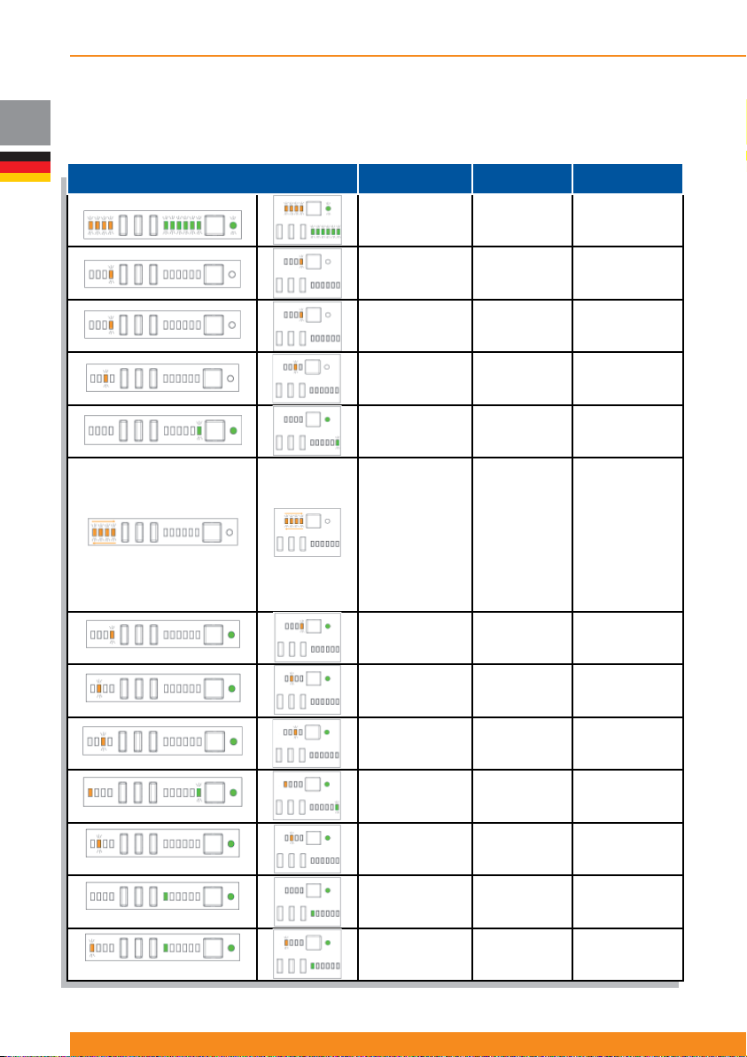
DE
Chloride Active
4.2.1.3 Anzeigen
LED Anzeige Indikatoren
Alle LEDs blinken
dreimal
LED 4 blinkt LED
1, 2 & 3 aus
LED 4 blinkt LED
1, 2 & 3 aus
LED 3 blinkt LED
1, 2 & 4 aus
LED 13 blinkt
dreimal
LED 4 AN
LED 3 AN
LED 2 AN
LED 1 AN
LED 1 AUS
LED 2 AUS
LED 3 AUS
LED 4 AUS
LED 4 AN
LED 4 blinkt LED
1, 2 & 3 aus
LED 2 blinkt LED
1, 3 & 4 aus
LED 3 blinkt LED
1, 2 & 4 aus
Akustisches
Signal
Drei Signaltöne Startsequenz
Kontinuierlicher
To n
Kontinuierlicher
To n
Abhängig vom
Fehler
Drei Signaltöne
Kontinuierlicher
To n
1 Signalton pro
Sekunde
1 Signalton pro
Sekunde
1 Signalton pro
Sekunde
USV Status
Überlastungsfehler
Wechselrichterkurzs
chluss
Andere USV
Fehler
Netzbetrieb nach
Batteriebetrieb
Ferng.
Abschalten
Warnung
Warnung
Überlast
Batterie nicht
angeschlossen
oder
Batterietestfehler
Fehler
Batterielader
58
945044.066
LED 1 AN, LED
13 blinkt
LED 2 blinkt LED
1, 3 & 4 aus
LED 8 AN -
LED 1 blinkt, LED
2, 3 & 4 AUS. LED
8 AN
1 Signalton alle
3 Sekunden
1 Signalton pro
Stunde
Kontinuierlicher
To n
Batteriekapazität
gering
LCM Alarm
(Ende der
Batterieüberbrückun
gszeit)
Erkennung
Anschlussfehler
aktiv
Anschlussfehler
erkannt
Page 61
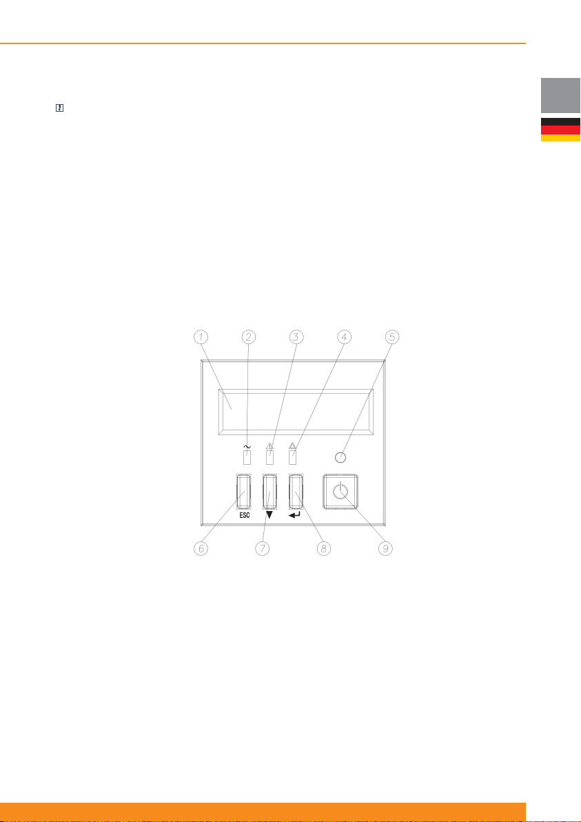
Chloride Active
4.2.2 LCD Anzeige
ANMERKUNG: Frontblenden mit LCD-Anzeige sind entweder im Standard-Lieferumfang enthalten oder
als Zubehör erhältlich
1. Display
2. LED Netz-Betrieb (leuchtet, wenn die Einheit im Netzbetrieb ist)
3. Batterie-Betrieb/Alarm LED (leuchtet, wenn die Einheit im Batterie-Betrieb ist oder ein Alarm gegeben
wird)
4. LED Bypass-Betrieb (leuchtet, wenn die Einheit im Bypass-Betrieb ist: Überlastung, manuell, ECO
Modus...)
5. AN LED (leuchtet, wenn die Einheit eingeschaltet ist)
6. ESC Taste (in der Menü Hierarchie einen Schritt nach oben)
7. Nach unten blättern Taste (in den Menüs und Untermenüs nach unten blättern)
8. ENTER Taste (in der Menü Hierarchie einen Schritt nach unten oder angezeigte Option auswählen)
9. EIN/AUS Schalter (schaltet die Einheit ein/aus)
DE
59
Page 62
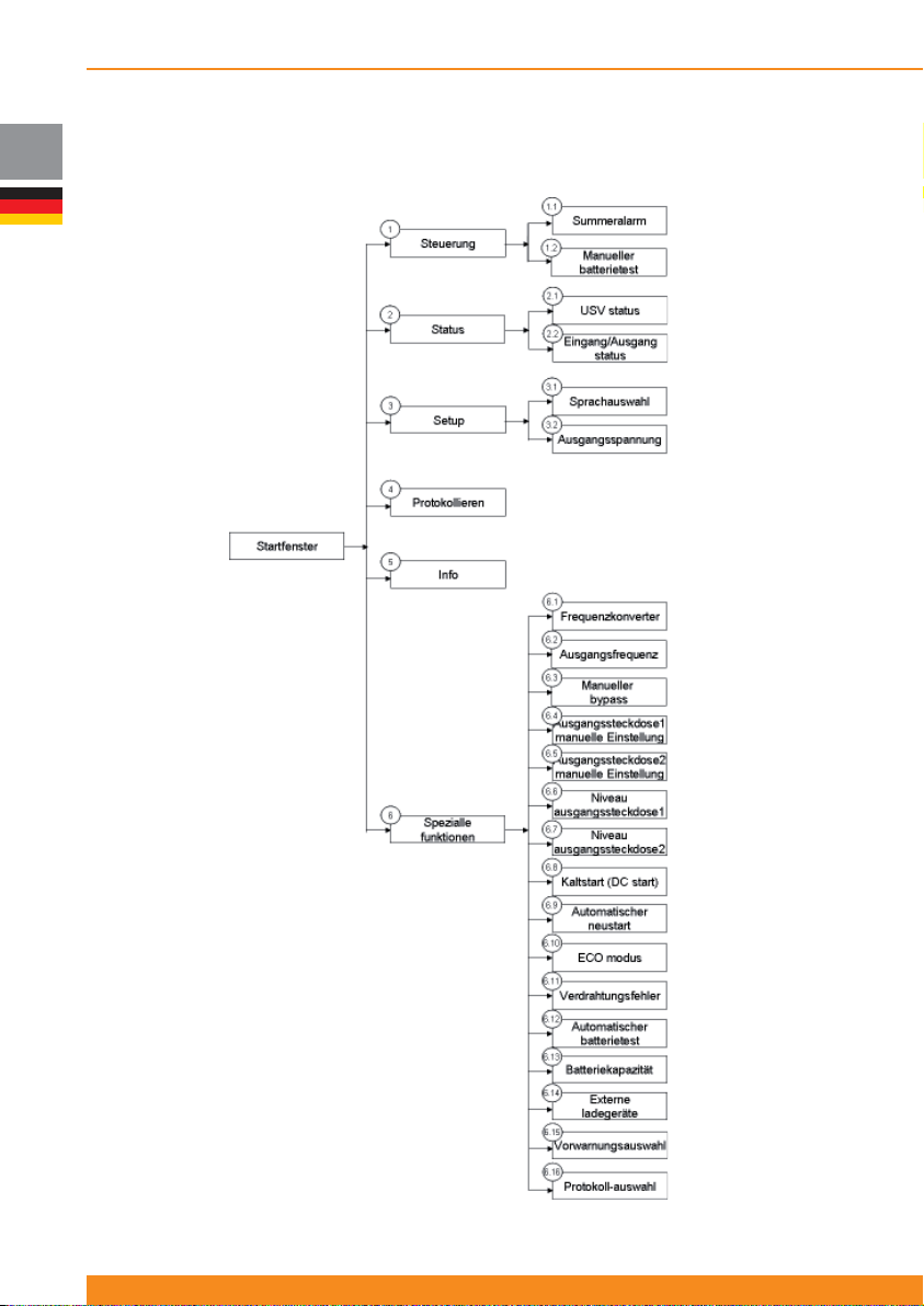
DE
Chloride Active
4.2.2.1 Menüs und Funktionen
Die Funktionen, die in den Menüs und Untermenüs zur Verfügung stehen, werden folgend beschrieben.
60
945044.066
Page 63
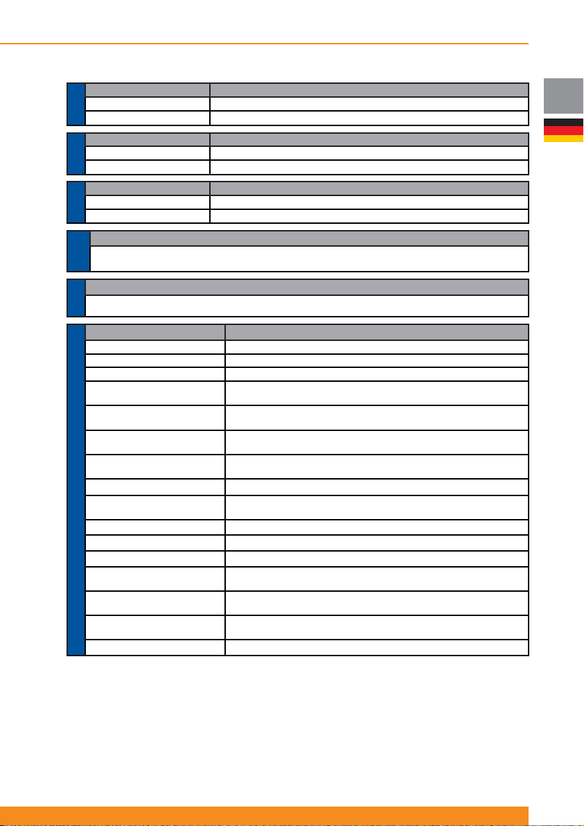
Chloride Active
Untermenü Funktion
1.1 Summeralarm Aktivierung oder Deaktivierung des akustischen Alarms (Summer)
MENÜ 1.-
1.2 Manueller Batterietest Führt einen Batterietest durch, wenn diese Option gewählt wurde
STEUERMENÜ
Untermenü Funktion
2.1 USV Status Zeigt den allgemeinen USV Status an (Betriebsmodus, Fehler, Warnungen…)
2.2 Eingang/Ausgang Status Zeigt Eingangs- und Ausgangswerte (Spannung, Frequenz, Last…)
MENÜ 2.-
STATUSMENÜ
Untermenü Funktion
3.1 Sprachauswahl
3.2 Ausgangsspannung Auswahl der Nennausgangsspannung (200 V, 208 V, 220 V, 230 V oder 240 V)
MENÜ 3.-
EINSTELLMENÜ
Zeigt die letzten fünf Ereignisse an (Fehler, Warnungen ...), die von der USV gegeben wurden Diese
MENÜ
MENÜ 4.-
PROTOKOLL
MENÜ INFO
MENÜ 5.-
Untermenü Funktion
6.1 Frequenzwandler
6.2 Ausgangsfrequenz
6.3 Manueller Bypass Forciert die USV, in den Bypass-Betrieb oder wieder zurück zu schalten
6.4 Ausgangssteckdose 1
manuelle Einstellung
6.5 Ausgangssteckdose 2
Manuelle Einstellung
6.6 Niveau Ausgangsbuchse 1
6.7 Niveau Ausgangsbuchse 2
6.8 Kaltstart (DC start) Aktiviert/Deaktiviert diese Funktion (Starten ohne Versorgungsnetz)
6.9 Automatischer neustart
6.10 ECO Modus
6.11 Anschlussfehler
MENÜ 6 – SPEZIALLE FUNKTIONEN
6.12 Automatischer Batterietest
6.13 Batteriekapazität
6.14 Externe ladegeräte
6.15 Vorwarnungsauswahl
6.16 Protokoll-Auswahl
Sprachauswahl (Englisch, Spanisch, Italienisch, Französisch, Portugiesisch, Deutsch)
Funktion
festgehaltenen Ereignisse werden in Abschnitt 4.2.2.2 erklärt
Funktion
Zeigt die Leistung, Seriennummer und Firmware Version der USV an
Aktiviert oder deaktiviert diesen Betriebsmodus (bitte sehen Sie 4.1.5 und 4.4.6 für weitere Details)
Auswahl der Nennausgangsfrequenz: 50Hz oder 60Hz (nur im Frequenzwandler Modus)
Schaltet Ausgangsbuchsen 1 an/aus (1. Gruppe der steuerbaren
Schaltet Ausgangsbuchsen 2 an/aus (2. Gruppe der steuerbaren
Wählt die verbleibende Batteriekapazität aus (75%, 50%, 25% oder 0%), bei der
Ausgangsbuchse 1 (1. Gruppe der steuerbaren Ausgangsbuchsen) automatisch abschaltet
Wählt die verbleibende Batteriekapazität aus (75%, 50%, 25% oder 0%), bei der
Ausgangsbuchse 2 (2. Gruppe der steuerbaren Ausgangsbuchsen) automatisch abschaltet
Aktiviert/Deaktiviert diese Funktion (automatisches Starten, nachdem die Batterieüberbrückungszeit
abgelaufen ist und die Spannung des Versorgungsnetzes wieder anliegt)
Aktiviert oder deaktiviert diesen Betriebsmodus (bitte lesen Sie 4.1.4 und 4.4.5 für weitere Details)
Aktiviert/Deaktiviert diese Funktion (Erkennen der Phase/Neutral Verdrehung)
Stellt das Intervall des automatischen Batterietests ein (täglich, wöchentlich, monatlich…)
Wählt die externe Batteriekapazität (Ah) für spezielle / individuelle Konfi gurationen, in
Schritten ab 9Ah bis 250Ah (Auswahl des Wertes mit der „Nach unten blättern“ Taste)
Wählt die Anzahl verbundener externer Batterielader aus (als Zubehör für
spezielle / individuelle Konfi gurationen erhältlich) aus; 1 bis 3 Stück
Wählt die verbleibende Batteriekapazität aus (75%, 50%, 25% oder 0%), bei
der das Alarmsignal „Batterie gering“ aktiviert wird
Auswahl des Kommunikationsprotokolls für spezielle Anwendung
Ausgangsbuchsen)
Ausgangsbuchsen)
DE
Menü 6 ist für erfahrene Anwender und der Zugang zu diesem Menü ist mit einem Passwort geschützt.
Bei Aufruf dieses Menüs werden Sie aufgefordert, eine spezielle Tastenkombination einzugeben (CODE
EINGEBEN (SIEHE MANUAL)). Korrekte Tastenkombination ist:
1. ESC Taste drücken und loslassen
2. Pfeil-nach-unten-Taste drücken und loslassen
3. ENTER-Taste drücken und loslassen
Nach Abschluss dieser Sequenz wird der Zugriff zum Menü ermöglicht und im Display wird ZUGANG ERLAUBT
ACHTUNG! angezeigt. Wenn nicht, erscheint eine Fehlermeldung (ZUGANG ABGELEHNT FALSCHER
CODE!).
61
Page 64
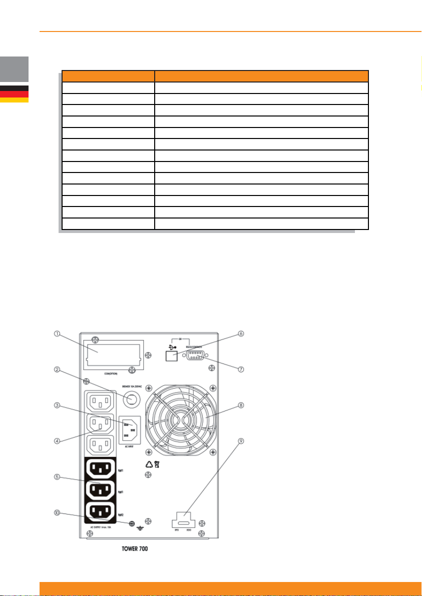
DE
Chloride Active
4.2.2.2 Warnmeldungen und Fehleranzeigen
Meldung Beschreibung
RPO AKTIV
BATTERIEFEHLER
WECHSELRICHTER ÜBERLAST
BYPASS ÜBERLAST
LÜFTERSTÖRUNG
LADEGERÄT ÜBERSPANNUNG
DC BUS ÜBERSPANNUNG
DC BUS UNTERSPANNUNG
DC BUS UNSYMETRIE
WECHSELRICHTER ÜBERSPANNUNG
WECHSELRICHTER UNTERSPANNUNG
WECHSELRICHTER KURZSCHLUSS
VERD. FEHLER
Das LCD Display zeigt die letzten fünf gespeicherten Ereignisse an. Sie werden von 1 bis 5 aufgelistet,
wobei 1 das jüngste und 5 das älteste Ereignis ist. Ereignis 1 ist das erste, das auf dem Display angezeigt
wird und Ereignis 2 bis 5 werden sequentiell durch Betätigen der „Nach unten blättern“-Taste angezeigt.
4.3 Rückseite
4.3.1 Tower Einheiten
Active 700 T:
USV gestoppt, weil RPO (Remote Power Off) aktiviert wurde
Ein Batteriefehler wurde festgestellt Bitte prüfen Sie die Batterien.
Am Wechselrichter wurde eine Überlastung festgestellt (Netzbetrieb oder Batterie-Betrieb)
Eine Überlastung wurde festgestellt, wenn die Einheit im Bypass-Betrieb ist
Ein Lüfterfehler wurde festgestellt
Der Batterielader liefert eine Überspannung (interner Fehler)
Spannung am DC Bus zu hoch (interner Fehler)
Spannung am DC Bus zu niedrig (interner Fehler)
Spannung am DC Bus ist asymmetrisch (interner Fehler)
Wechselrichter liefert Überspannung (interner Fehler)
Wechselrichter liefert Unterspannung (interner Fehler)
Kurzschluss im Wechselrichter (interner Fehler)
Anschlussfehler erkannt. Bitte prüfen Sie die Netzstecker Verkabelung.
62
945044.066
1. SNMP Steckplatz
2. Schutzschalter
Eingangsstromkreis
3. Netzanschluss
4. Nicht steuerbare
Ausgangsbuchsen
5. Steuerbare Ausgangsbuchsen (2
Gruppen)
6. USB Schnittstelle
7. RS232 Schnittstelle
8. Lüfter
9. ROO/RPO Schnittstelle
10. Erdungsschraube
Page 65
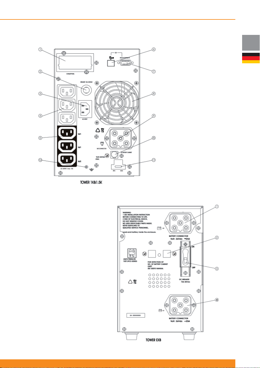
Active 1000 T und Active 1500 T:
BP-A1000/1500-T:
Chloride Active
1. SNMP Steckplatz
2. Schutzschalter
Eingangsstromkreis
3. Netzanschluss
4. Nicht steuerbare
Ausgangsbuchsen
5. Steuerbare Ausgangsbuchsen (2
Gruppen)
6. USB Schnittstelle
7. RS232 Schnittstelle
8. Lüfter
9. Anschluss externer Batteriepacks
10. RJ11 Schnittstelle für
Batteriepack- Erkennungskabel
11. ROO/RPO Schnittstelle
12. Erdungsschraube
DE
1. Anschluss externer Batteriepacke
2. RJ11 Schnittstelle für Batteriepack
Erkennungskabel
3. Schutzschalter
4. Anschluss externer Batteriepack
63
Page 66
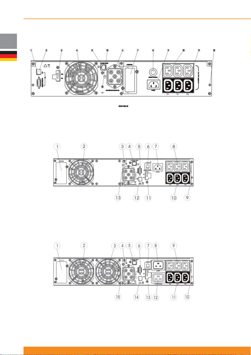
DE
Chloride Active
4.3.2 Rack/Tower Einheiten
Active 1000 RT und Active 1500 RT:
1. RS232 Schnittstelle
2. USB Schnittstelle
3. ROO/RPO Schnittstelle
4. Lüfter
5. RJ11 Schnittstelle für Batteriepack
Erkennungskabel
Active 2000 RT:
1. SNMP Steckplatz
2. Lüfter
3. Anschluss externes Batteriepack
4. RJ11 Schnittstelle für Batteriepack
Erkennungskabel
5. RS232 Schnittstelle
Active 3000 RT:
6. Anschluss externes Batteriepack
7. SNMP Steckplatz
8. Schutzschalter Eingangsstromkreis
9. Netzanschluss
10. Nicht steuerbare
Ausgangsbuchsen
6. Schutzschalter Eingangsstromkreis
7. Netzanschluss
8. Nicht steuerbare Ausgangsbuchsen
9. Befestigungspunkt Gleitschienen
10. Steuerbare Ausgangsbuchsen (2
Gruppen)
11. Steuerbare Ausgangsbuchsen (2
Gruppen)
12. Befestigungspunkt Gleitschienen
13. Erdungsschraube
11. ROO/RPO Schnittstelle
12. USB Schnittstelle
13. Erdungsschraube
1. SNMP Steckplatz
2. Lüfter
3. Lüfter
4. Anschluss externes Batteriepack
5. RJ11 Schnittstelle für Batteriepack
Erkennungskabel
64
945044.066
6. RS232 Schnittstelle
7. Schutzschalter Eingangsstromkreis
8. Netzanschluss
9. 10 Ampere nicht steuerbare
Ausgangsbuchsen
10. Befestigungspunkt Gleitschienen
11. 10 Ampere steuerbare
Ausgangsbuchsen (2 Gruppen)
12. 16 Ampere Ausgangsbuchse
13. ROO/RPO Schnittstelle
14. USB Schnittstelle
15. Erdungsschraube
Page 67
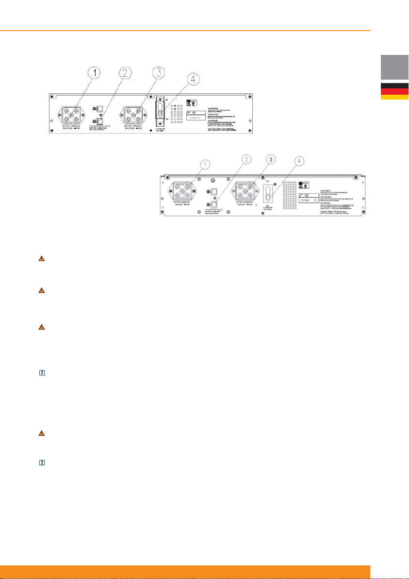
Chloride Active
BP-A1000/1500-RT:
1. Anschluss externes Batteriepack
2. RJ11 Schnittstelle für Batteriepack
Erkennungskabel
3. Anschluss externes Batteriepack
4. Schutzschalter
BP-A2000/3000-RT:
1. Anschluss externes Batteriepack
2. RJ11 Schnittstelle für Batteriepack
Erkennungskabel
3. Anschluss externer Batteriepacke
4. Schutzschalter
4.4 Inbetriebnahme und Abschalten
4.4.1 Elektrische Vorbereitungsarbeiten
WARNUNG: : Bevor Sie ein Eingangskabel an die USV anschließen, vergewissern Sie sich, dass
alle benutzten Stromkreise und Anschlüsse die für den Betrieb der USV erforderliche Spannung und
Stromstärke haben.
WARNUNG: Sobald die USV mit dem Eingangsnetz verbunden ist, liegt an den Ausgangsbuchsen
Spannung an (über den internen Bypass), selbst, wenn der Wechselrichter EIN Schalter nicht
betätigt wurde. Wenn dieser Knopf betätigt wurde, ist der Wechselrichter ein und die USV arbeitet im
Doppelwnadlerbetrieb.
WARNUNG: Stromschlaggefahr: Selbst wenn die USV vom Versorgungsnetz abgeklemmt ist, können
gefährliche Spannungen an den Ausgangssteckern der USV anliegen. Die USV wird von mehr als
einer Stromquelle versorgt - Wechselstrom Eingang und Gleichstrom Eingang von den Batterien. Alle
Stromversorgungsquellen (Wechselstrom und Gleichstrom) sind abzuklemmen , bevor Wartungsarbeiten
an der USV vorgenommen werden.
ANMERKUNG: Nach den EMV-Richtlinien dürfen Ausgangskabel nicht länger als 10 Meter,
Kommunikationskabel nicht länger als 3 Meter und Batterie-Verlängerungskabel nicht länger als 3 Meter
sein.
4.4.2 Anschlüsse
4.4.2.1 Anschluss externer Batteriepacks
WARNUNG: : Bevor ein Batteriepack an die USV angeschlossen wird, muss der Schalter des
Batteriepacks auf “AUS” geschaltet sein. Nachdem die elektrische Verbindung zur USV steht, muss der
Schalter des Batteriepacks auf “EIN” geschaltet werden..
ANMERKUNG: JJedes Batteriepack hat zwei Batterie-Anschlüsse. Das erste Batteriepack wird mit
der USV über das mitgelieferte Kabel verbunden. Jedes weitere Batteriepack wird per Kabel mit dem
vorherigen Pack verbunden
Werden externe Batteriepacks eingesetzt, sollten sie angeschlossen sein, bevor die USV mit dem
Versorgungsnetz verbunden wird. Beim Anschluss externer Batterieschränke, gehen Sie wie folgt vor:
1. Schalten Sie den Schutzschalter an jedem Batterieschrank auf “AUS”
2. Stecken Sie ein Batterie-Erweiterungskabel auf der einen Seite in die Batterie-Anschlussbuchse der USV
und auf der anderen Seite in die an der Rückseite des ersten Batteriepacks befi ndlichen Buchse.
DE
65
Page 68
DE
Chloride Active
3. Stecken Sie ein Batterie-Erweiterungskabel auf der einen Seite in die Anschlussbuchse auf der
Rückseite der Batterie des ersten Batteriepacks und auf der anderen Seite in die an der Rückseite des
zweiten Batteriepacks befi ndlichen Buchse.
4. Schließen Sie alle Batteriepacke weiter in Reihe an.
5. Verbinden Sie ein Batteriepack-Erkennungskabel mit der RJ11-Buchse auf der Rückseite der USV mit
einer RJ11-Buchse auf der Rückseite des ersten Batteriepacks.
6. Verbinden Sie ein Batterie-Erkennungskabel an die RJ11-Buchse auf der Rückseite des ersten
Batteriepacks mit einer RJ11-Buchse auf der Rückseite des zweiten Batteriepacks.
7. Schließen Sie die Batteriepacke mit dem Batteriepack-Erkennungskabel weiter in Reihe, bis alle Packe
verbunden sind.
8. Schalten Sie den Schutzschalter an jedem Batterieschrank auf “EIN”.
ANMERKUNG: Es können maximal 4 externe Batteriepacks die an die USV angeschlossen werden.
ANMERKUNG: Für spezielle oder individuelle externe Batteriekonfi gurationen ist es möglich, die Kapazität
externer Batterien über das Display auszuwählen.
4.4.2.2 Anschluss an das Versorgungsnetz
Nachdem alle externen Batterien verbunden sind, nehmen Sie die notwendigen Anschlüsse an das
Versorgungsnetz und die Ausgangsanschlüsse wie folgt vor:
1. Verbinden Sie das Netzkabel mit der Wechselstrom-Steckdose.
ANMERKUNG: Die Batterien werden geladen, sobald Spannung am Lademodul anliegt.
WARNUNG: sobald die USV mit dem Hauptnetz verbunden ist, liegt an den Ausgangsbuchsen Spannung
an (über den interne Bypass), selbst, wenn der Wechselrichter EIN Schalter nicht betätigt wurde.
2. Verbinden Sie die Last (zu versorgendes Equipment) mit der USV. Es wird empfohlen, das Equipment
mit höherer Priorität an die Hauptausgangsstecker anzuschließen und die Geräte mit geringerer Priorität an
die steuerbaren Ausgangsstecker.
ANMERKUNG: Über das LCD-Display oder die Software lassen sich die Ausgangsbuchsen so
konfi gurieren, dass zu einem voreingestellten Zeitpunkt im Batteriebetrieb abgeschalten wird, um
Batterieleistung für die Geräte mit höherer Priorität zu sparen.
3. Nachdem alle Verbindungen hergestellt sind, folgen Sie den Anweisungen im nächsten Abschnitt (“USV
Start-up”), um USV und externe Batteriepacks zu starten.
4.4.3 USV - Inbetriebnahme
ACHTUNG: Die USV ist mit Standard-Stromkabel und Steckdosen ausgestattet,. Die Einheit kann auch
von Nicht-Technikern installiert und betrieben werden.
4.4.3.1 Erst-Inbetriebnahme
ACHTUNG: Wird die USV erstmals angeschlossen,, muss Spannung vom Versorgungsnetz anliegen.
Einheiten mit LED-Anzeige Einheiten mit LCD-Anzeige
Wird die USV erstmals eingesetzt, vergewissern Sie sich,
dass die Netzspannung vorhanden ist. Entsprechend 4.4.2.2
sollten die angeschlossenen Verbraucher über den internen
Bypass versorgt werden, sobald die Netzverbindung zum
USV-Eingang besteht.
Durch Betätigung des Wechselrichter- AN/AUS-Schalters wird
die USV in den Doppelwandlermode geschalten.
Die USV gibt Signaltöne von sich und LEDs leuchten auf.
LED „Netzanschluss“ und Wechselrichter „AN“ zeigen an,
dass die Einheit im Doppelwandlerbetrieb ist.
Das an die USV angeschlossene Equipment wird nun über
den Wechselrichter mit Strom versorgt.
Wird die USV erstmals eingesetzt, vergewissern Sie sich, dass
Netzspannung vorhanden ist. Entsprechend 4.4.2.2 sollten die
angeschlossenen Verbraucher über den internen Bypass versorgt
werden, sobald die Netzverbindung zum USV-Eingang besteht.
Durch Betätigung des Wechselrichter- AN/AUS-Schalters wird die
USV in den Doppelwandlermode geschalten.
USV gibt Signaltöne von sich und LED „Netzanschluss“
und Wechselrichter „AN“ zeigen an, dass die Einheit im
Doppelwandlerbetrieb ist.. Auf dem LCD wird die Meldung LAST
GESCHÜTZT und die Ausgangsleistung angezeigt.
Das an die USV angeschlossene Equipment wird nun über den
Wechselrichter mit Strom versorgt
66
945044.066
Page 69
4.4.3.2 Normaler Start-Up
Einheiten mit LED Indikatoren Einheiten mit LCD Anzeige
Entsprechend 4.4.2.2 sollte Spannung am
angeschlossenen Equipment via internem Bypass
anstehen, sobald der USV-Eingang mit dem
Versorgungsnetz verbunden ist (wenn Netzspannung
verfügbar).
Betätigen Sie den Wechselrichter EIN/AUS Schalter um
den Wechselrichter einzuschalten; oder betätigen Sie
ihn zweimal, wenn keine Netzspannung verfügbar ist
und „Kaltstart“ aktiviert wurde, um im Batterie-Modus
zu starten..
USV gibt Signaltöne von sich und LED leuchtet auf.
Liegt Netzspannung an der USV an, leuchten die LEDs
„Netzbetrieb“ und Wechselrichjter AN und zeigen, dass
die USV im Doppelwandlermode arbeitet.
Liegt keine Netzspannung an der USV an und ist
die „Kaltstart“-Funktion aktiviert, leuchtet die LED
„Batteriebetrieb“ und zeigt, dass die Einheit nun Strom
von der Batterie liefert.
ACHTUNG: Wenn die LED „ Überlast“ leuchtet oder
die Anzeige “LOAD”/LAST über 100% angezeigt, sind
zu viele Geräte an die USV angeschlossen. Wenn nur
ein Gerät an die USV angeschlossen ist und „Überlast“
angezeigt wird, fordert das angeschlossene Gerät mehr
Leistung, als die USV liefern kann. Hier empfi ehlt es sich,
eine USV mit höherer Leistung einzusetzen.
ANMERKUNG: Wenn die USV nicht wie oben
beschrieben reagiert, lesen Sie bitte Abschnitt 7
(„Fehlerbehebung“).
Chloride Active
Entsprechend 4.4.2.2 sollte Spannung am
angeschlossenen Equipment via internem Bypass
anstehen, sobald der USV-Eingang mit dem
Versorgungsnetz verbunden ist (wenn Netzspannung
verfügbar).
Betätigen Sie den Wechselrichter EIN/AUS-Schalter
um den Wechselrichter einzuschalten; oder betätigen
Sie ihn zweimal, wenn keine Netzspannung verfügbar
ist und Kaltstart aktiviert wurde, um im Batterie-Modus
zu starten..
USV gibt Signaltöne von sich und LED leuchtet auf.
Liegt Netzspannung an der USV an, leuchten die LEDs
„Netzbetrieb“ und Wechselrichjter AN und zeigen, dass
die USV im Doppelwandlermode arbeitet..Auf dem
LCD wird die Meldung LAST GESCHÜTZT und die
Ausgangsleistung angezeigt
Liegt keine Netzspannung an der USV an und ist
die Kaltstart-Funktion aktiviert, leuchtet die LED
„Batteriebetrieb“ auf und zeigt an, dass die Einheit
nun Strom über die Batterie liefert. Das LCD-Display
meldet NETZAUSFALL und die geschätzte, verbleibende
Überbrückungszeit.
ACHTUNG: Meldet das Display ÜBERLAST,, sind zu
viele Geräte an die USV angeschlossen. Ist nur ein Gerät
an die USV angeschlossen und das Display meldet
ÜBERLAST, fordert das angeschlossene Gerät mehr
Leistung, als die USV liefern kann. . Hier empfi ehlt es
sich, eine USV mit höherer Leistung einzusetzen.
ANMERKUNG: Wenn die USV nicht wie oben
beschrieben reagiert, lesen Sie bitte Abschnitt 7
(„Fehlerbehebung“).
DE
4.4.4 Interner Bypass
Einheiten mit LED-Anzeige Einheiten mit LCD-Anzeige
Um die USV in Bypass-Betrieb umzustellen, halten Sie
die Tasten 5 und 6 für vier Sekunden gedrückt (siehe
Abbildungen. des Abschnitts 4.2.1). Die USV wird auf
Bypass-Betrieb umgeschalten und die LED „Bypass-Betrieb“
leuchtet auf. Folgen Sie der gleichen Vorgehensweise, um
die USV wieder auf Doppelwandlerbetrieb umzustellen.
Für weitere Informationen zum Bypass-Betrieb, lesen Sie
bitte Abschnitt 4.1.3.
Um die USV in Bypass-Betrieb umzustellen, gehen Sie ins
Menü 6 (Spezielle Funktionen) und dann in das Untermenü
„Manueller Bypass“ und wählen Sie USV AUF BYPASS
SCHALTEN. Folgen Sie der gleichen Vorgehensweise, um
durch USV AUF ONLINE SCHALTEN die USV wieder auf
Doppelwandlerbetrieb umzustellen.
Für weitere Informationen zum Bypass-Betrieb, lesen Sie
bitte Abschnitt 4.1.3.
4.4.5 ECO Modus Aktivierung/Deaktivierung
ANMERKUNG: :Diese Funktion kann nicht bei Einheiten mit LED-Anzeige aktiviert / deaktiviert werden.
Vorgehensweise zur Aktivierung des ECO-Modus:
Während die USV im Doppelwandlerbetrieb läuft, wählen Sie am LCD das Menü 6 (Spezielle Funktionen)
und gehen ins Untermenü „ECO MODUS“, wo Sie „ECO MODUS AKTIVIEREN“ wählen. Um die USV
wieder in den Doppelwandler-Modus zurückzuschalten gehen Sie in das gleiche Untermenü und wählen
„ECO MODUS DEAKTIVIEREN“.,
Für weitere Informationen zum ECO-Modus, leen Sie bitte Abschnitt 4.1.4.
67
Page 70
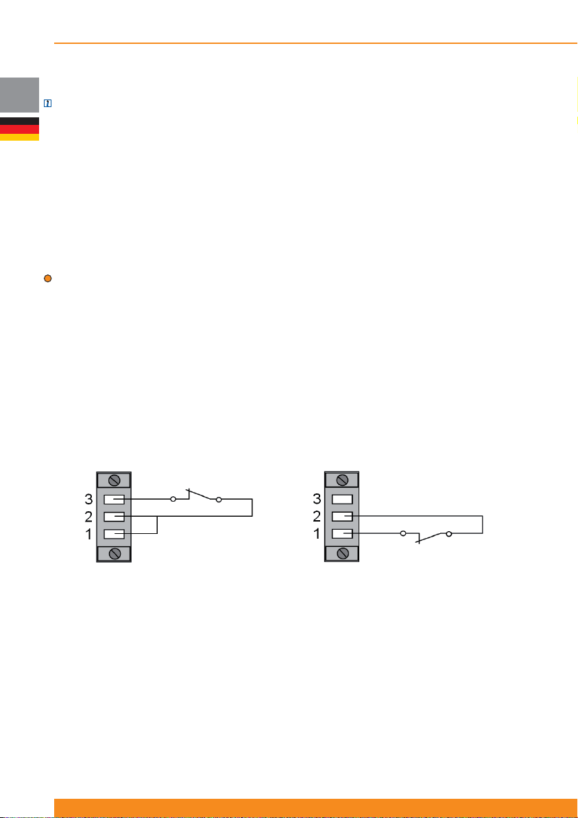
DE
Chloride Active
4.4.6 Frequenzwandler-Modus aktivieren
ANMERKUNG: Diese Funktion kann nicht bei Einheiten mit LED-Anzeige aktiviert / deaktiviert werden.
Im Frequenzwandler-Modus ist es möglich die Ausgangsfrequenz (50 oder 60 Hz) über die LCD-Anzeige einzustellen.
Dabei muss die Eingangsfrequenz zwischen 40 und 70 Hz liegen und die Netzeingangsspannung im Toleranzbereich
liegen, da sonst die Last über die Batterie (50 oder 60 Hz, wie gewählt) versorgt wird.
Zur Umstellung müssen Sie in den Bypassbetrieb umschalten und wählen dann im Menü 6 (Spezielle Funktionen) das
Untermenü „FREQUNZWANDLER“. Dort wählen Sie „FREQUENZKONVERT. AKTIVIEREN“. Anschließend wählen Sie
im Untermenü „AUSGANGSFREQUENZ“ „50 HZ“ oder „60 HZ“.
Nun schalten Sie die USV völlig ab. D. h., Sie trennen die USV vom Netzeingang, damit sie abschaltet. Wenn Sie die
USV neu starten, wird sie im Frequenzwandler-Modus mit der ausgewählten Ausgangsfrequenz starten.
Bei der Deaktivierung müssen Sie ebenfalls im Bypassbetrieb über das Menü 6 (Spezielle Funktionen) und das
Untermenü „FREQUNZWANDLER“ gehen. Dort wählen Sie „FREQUENZKONVERT. DEAKTIVIEREN“ und können
durch Betätigen der Wechselrichter „EIN/Aus“-Taste wieder in den Doppelwandler-Modus umschalten
ACHTUNG: Im Frequenzwandler- Modus reduziert sich die Leistung um 50%. Dies bedeutet, dass nur 50% der
nominalen Leistung der USV benutzt werden kann.
Für weitere Informationen zum Betrieb Frequenzwandler-Modus, lesen Sie bitte Abschnitt 4.1.5.
4.4.7 USV abschalten
Betätigen Sie den EIN/AUS-Schalter. Der Wechselrichter wird ausgeschaltet, aber die USV wird die angeschlossenen
Geräte über den internen Bypass weiter versorgen. Um alle Ausgangsbuchsen und die Einheit auszuschalten, ist es
notwendig, die USV vom Versorgungsnetz zu trennen.
Um die USV zu starten, lesen Sie bitte Abschnitt 4.4.3.2 (“Normaler Start-Up“)
4.4.8 Remote Power Off (RPO) / Remote On Off (ROO)
Der externe Anschluss an den RPO/ROO-Kreis befi ndet sich auf der Geräte-Rückseite. Er besteht aus einem
Anschluss mit drei Klemmen, wie in der nfl gd. Abbildung gezeigt.
ROO RPO
Die USV wird mit einem Kabel ausgeliefert, das die Kontakte 1 und 2 verbindet. Diese zwei Kontakte müssen für
„normalen Betrieb“ verbunden bleiben.
Um die Remote Power Off (RPO) Funktion zu nutzen, entfernen Sie bitte dieses Kabel und verbinden Sie Kontakt 1
und 2 mit einem normal geschlossenen, potenzialfreien Kontakt. Ist dieser Kontakt offen, wird die USV abgeschaltet.
Um in den „normalen Betrieb“ zurückzugelangen, schließen Sie den Kontakt und starten Sie die USV entsprechend der
Vorgehensweisen in Abschnitt 4.4.3.2.
Um die Remote On Off (ROO) Funktion zu nutzen, verbinden Sie Kontakt 1 und 2 mit dem Kabel (die USV wird mit
diesem Kabel geliefert) und verbinden Sie außerdem Kontakt 2 und 3 mit einem normal geschlossenen potenzialfreien
Kontakt. Ist dieser Kontakt offen, wird die USV abgeschaltet. Wird der Kontakt anschließend geschlossen, schaltet sich
die Einheit ein und versorgt die angeschlossenen Geräte.
Für weitere Details zu ROO/RPO Betrieb, lesen Sie bitte Abschnitt 4.1.6.
68
945044.066
Page 71
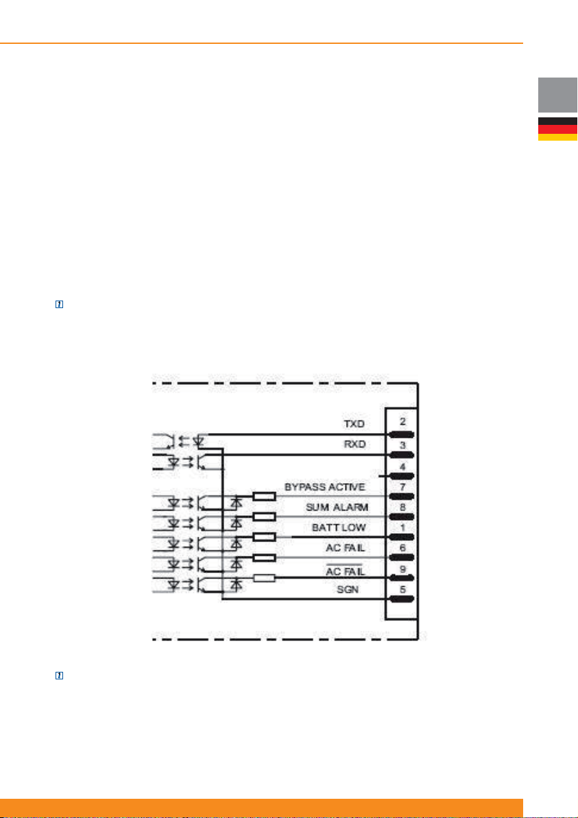
Chloride Active
5 Kommunikationschnittstellen
Die USV ist mit einer seriellen Schnittstelle (RS232 und USB) und mit einem Steckplatz für eine
Kommunikationsschnittstelle ausgestattet. Diese Schnittstellen können benutzt werden für:
- Direkte Kommunikation zwischen USV und Workstation/Server
- Integration der USV als Client in einem Netzwerk mit zentraler Überwachung via ManageUPS SNMPAdapter im Schnittstellen-Steckplatz
- Übermittlung des Betriebsstatus an externe Alarmsysteme via potenzialfreien Kontakten (mit einer
Schnittstellenkarte mit potenzialfreien Kontakten für Schnittstellen-Steckplatz, als Zubehör erhältlich).
Die notwendigen Kommunikationssoftware-Pakete und Schnittstellenkabel und Karten werden entweder
mit der Einheit ausgeliefert oder sind als Zubehör erhältlich.
5.1 Serielle Schnittstelle
Es sind 2 serielle Schnittstellen verfügbar: Als DB9-Port (RS232) und als USB-Port.
ANMERKUNG: können nicht beide Schnittstellen gleichzeitig benutzt werden.
5.2 DB9 Port
Die 9-polige SUB-D-Buchse überträgt RS232-kompatible Signale.
DE
ANMERKUNG: Diese Schnittstelle ist von allen anderen Kreisen elektrisch isoliert.
Neben der RS232-Schnittstelle sind fünf opto-gekoppelte Signalpins als Open-Collector Ausgänge
verfügbar. Die Kontaktbelegung der Pins ist wie folgt(siehe vorherige Figur):
- SGN an Pin 5: Dieser Anschluss ist die Referenz für alle Signale
- RxD an Pin 3 und TxD an Pin 2: entspricht der normaler Pin-Belegung einer RS232-Schnittstelle
69
Page 72

DE
Chloride Active
- BATTERY LOW an Pin 1: Dieses Signal ist aktiv, wenn die Batteriekapazität unter dem voreingestellten
Wert liegt (bitte sehen Sie Abschnitt 4.2 für weitere Details zur Einstellung dieses Wertes) oder wenn die
verfügbare Backup-Zeit weniger als eine Minute beträgt.
- AC FAIL (low-aktiv an Pin 9 und high-aktiv an Pin 6): Dieses Signal ist aktiv, wenn die Netzspannung
an der USV für mindestens 10 Sekunden ausgefallen ist oder die Netzspannung außerhalb
des Toleranzbereichs liegt. Das Signal wird 850 ms nach Wiederherstellung der Netzspannung
zurückgenommen.
- BYPASS ACTIVE an Pin 7: Dieses Signal ist aktiv, wenn das Gerät in den Bypass-Betrieb umgeschaltet
wurde, der Konverter gesperrt ist und Netz-Stromversorgung vorliegt.
- SUM ALARM an Pin 8: Dieses Signal ist „low“, wenn einer der Alarmmeldungen “BATTERY LOW”, “AC
FAIL” oder “BYPASS ACTIVE” aktiv ist.
5.3 USB-Schnittstelle
Wie die RS232-Schnittstelle, ermöglicht die USB-Schnittstelle den seriellenDatentransfer. Der USB-Port an
der USV ist als HID (Human Interface Device) klassifi ziert.
5.4 Schnittstellensteckplatz
Der Schnittstellensteckplatz kann mit verschiedenen optionalen Karten bestückt werden. Die Anschlüsse,
Bezeichnungen und Codes am Steckplatz sind daher von der Art der eingesetzten Schnittstellenkarte
abhängig. Eine detaillierte Beschreibung liegt den Schnittstellenkarten bei, die als Zubehör erhältlich sind.
Verfügbare Schnittstellenkarten:
- SNMP Adapter-Karte (ManageUPS), um die USV in ein Netzwerk zu integrieren
- Karten mit potenzialfreien Kontakten
Bitte sehen Sie dazu in der verfügbaren Literatur nach oder fragen Sie den Fachberater in Ihrer Nähe
70
945044.066
Page 73

Chloride Active
6 Wartung
6.1 Reinigung
Benutzen Sie kein Scheuerpulver oder Plastik lösende Reinigungsmittel, um die USV zu reinigen.
Es darf keine Flüssigkeit in das Innere der USV gelangen.
Stellen Sie sicher, dass die Lüftungsschlitze der USV nicht abgedeckt sind. Entfernen Sie mit einem
Staubsauger den Staub von den Lüftungsschlitzen.
Reinigen Sie die äußeren Flächen des USV-Gehäuses mit einem trockenen oder leicht feuchten Tuch.
6.2 USV-Lagerung
Für längere Lagerung in Umgebungen mit Temperaturen höher als 25ºC sollten die Batterien alle vier
Monate für 5 Stunden aufgeladen werden. Bei höheren Lagertemperaturen sollte dieser Intervall zwei
Monate betragen.
Um die Batterien zu laden, ist es nicht notwendig, sie aus der Einheit auszubauen. Verbinden Sie einfach
die USV mit einer angemessenen Stromquelle an der entsprechenden Öffnung in der Verpackung und
laden Sie die Batterien für etwa fünf Stunden. Nach dem Aufl aden notieren Sie sich das Datum der Ladung
auf der USV-Verpackung.
6.3 Batterietest
Die USV erfordert keine Wartungsarbeiten seitens des Benutzers; jedoch sollten die Batterien regelmäßig
geprüft werden.
Die USV wird automatisch einmal pro Woche einen Batterietest durchführen. Wird ein Problem festgestellt,
leuchtet das LED „Batteriefehler“ auf oder das LCD-Display zeigt die entsprechende Fehlermeldung.
Lesen Sie Abschnitt 7 (“Fehlerbehebung”).
Die Häufi gkeit der Tests kann über das LCD-Display oder per Software geändert werden. Es ist einstellbar,
ob der Batterie-Selbsttest einmal pro Monat, pro Woche, täglich oder nie durchzuführen ist.
6.4 Batterietausch
WARNUNG: Für den Austausch der eingebauten Batterie können Sie den Austauschservice von Chloride
nutzen. Dazu kontaktieren Sie die Servicezentrale, deren Adresse in den entprechenden Broschüren oder
über die Internetseiten von Chloride zu fi nden ist.
ACHTUNG: die an die USV angeschlossenen Geräte werden bei dieser Prozedur nicht vor
Leistungsausfall geschützt sein.
6.4.1 Die internen Batterien der USV austauschen
Für das Ersetzen der Batterien in einer Zone mit Kundenservice:
- Arbeiten an den Batterien sollte von Personen überwacht oder durchgeführt werden, die Kenntnisse über
Batterien und die erforderlichen Vorsichtsmassnahmen haben
- Die Batterien der USV und der externen Batteriepaketen enthalten Akkumulatorsäure. Unter normalen
Bedingungen sind die Batterien trocken. Aus einer beschädigten Batterie kann Säure austreten, die in
Kontakt mit der Haut gefährlich ist und in den Augen Reizungen verursachen kann. Wenn dieser Fall
eintreten sollte, waschen Sie die betroffene Stelle ausgiebig mit Wasser und suchen Sie sofort einen Arzt
auf.
- Wenn Sie die Batterien ersetzen, wählen Sie Batterien des gleichen Typs und der gleichen Anzahl
Batterien oder Batteriepaketen.
- Entsorgen Sie Batterien nie in einem Feuer. Die Batterien können explodieren.
- Öffnen oder beschädigen Sie nie das Batteriegehäuse. Ausgelaufene Batteriesäure ist für Haut und
Augen gefährlich und kann giftig sein.
- Eine Batterie kann einen elektrischen Schlag und einen hohen Kurzschlussstrom verursachen. Die
folgenden Vorsichtsmassnahmen sollten beachtet werden, wenn man mit Batterien arbeitet:
Entfernen Sie Uhren, Ringe oder andere Metallobjekte
Benutzen Sie Werkzeug mit isoliertem Griff
Tragen Sie Gummihandschuhe und Schuhe mit Gummisohle
DE
71
Page 74
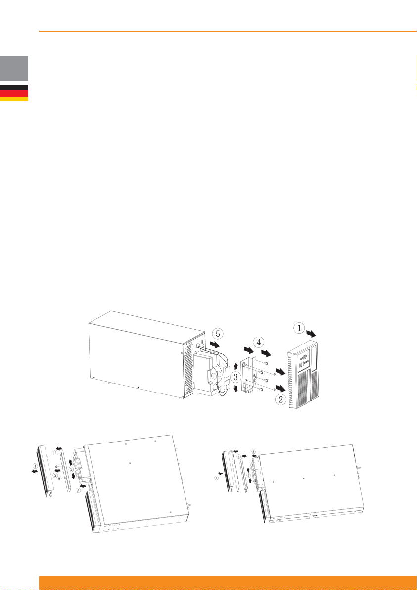
DE
Chloride Active
Legen Sie keine Werkzeuge oder Metallteile oben auf die Batterien.
Trennen Sie alle Ladequellen, bevor Sie die Batteriekontakte an- oder abklemmen.
Prüfen Sie, ob die Batterie eine falsche Erdung hat. Wenn dem so ist, entfernen Sie die Quelle vom
Erdungsanschluss. Der Kontakt mit irgendeinem Teil einer geerdeten Batterie kann einen elektrischen
Schlag verursachen. Die Wahrscheinlichkeit eines solchen Schlags kann reduziert werden, indem
solche Erdungskontakte während der Installation und Wartung entfernt werden (anzuwenden bei
Equipment und Batterieversorgung, die keinen Versorgungsanschluss mit Erdung haben).
Die USV erfordert keine Wartungsarbeiten seitens des Benutzers; jedoch sollten die Batterien in
Übereinstimmung mit IEEE Empfohlene Praxis für Wartungen, Tests und Ersetzen von Ventil regulierten
Blei-Säure (VRLA) Batterien für stationären Einsatz (IEEE Std 1188-1996) gewartet werden. Wenn
die Haltbarkeitszeit der Batterien abgelaufen ist, müssen sie von ausgebildetem Service-Personal
ausgetauscht werden. Eine zertifi zierte Entsorgungs-/Recycling-Firma sollte die Entsorgung/das Recycling
der USV und/oder der Batterien übernehmen. Verbrauchte wieder aufl adbare Batterien werden als
“gefährlicher und giftiger Abfall” klassifi ziert und dies fordert eine Entsorgung/ein Recycling durch ein
authorisiertes Recycling-Center.
Das Service-Center des Herstellers ist voll ausgestattet, um solche Batterien in Übereinstimmung mit dem
Gesetz und mit grösstem Respekt für die Umwelt zu handhaben. Kontaktieren Sie Ihren Kundendienst
Vertreter, um Personal für die Wartung und/oder das Austauschen der Batterien anzufordern.
Der typische Haltbarkeitszeitraum einer Batterie liegt zwischen 3 und 5 Jahren, bei einer
Umgebungstemperatur von 25ºC. Jedoch hängt die Haltbarkeit von Batterien ebenfalls von der Häufi gkeit
und Dauer von Stromausfällen oder den Batterie Entladezyklen ab.
Der BATTERY TEST (siehe 6.3 “Batterietest”) sollte regelmässig durchgeführt werden (zwischen 6 und 12
Monaten), um den allgemeinen Zustand der Batterien zu prüfen.
Um die internen Batterien der USV zu ersetzen, stellen Sie die USV manuell in den Bypass-Betrieb um
(siehe „Forcierter Bypass“ in Abschnitt 4.4.4) und folgen Sie den Schritten, die in der nächsten Figur
dargestellt sind.
72
945044.066
Tower Modelle
1 / 1,5 kVA Rack/Tower Einheiten 2 / 3 kVA Rack/Tower Einheiten
Page 75
Chloride Active
6.4.2 Entsorgen der Batterie
Der typische Haltbarkeitszeitraum einer Batterie liegt zwischen 3 und 5 Jahren, bei einer
Umgebungstemperatur von 25ºC, hängt jedoch auch von der Häufi gkeit und Dauer der Stromausfälle ab
Wenn die Haltbarkeitszeit einer Batterie abgelaufen ist, folgen Sie der Vorgehensweise für das Ersetzen
der Batterien (Abschnitt 6.4.1).
Nachdem die Batterien ausgetauscht wurden, sollte eine zertifi zierte Entsorgungs-/Recycling Firma die
Entsorgung/das Recycling der alten Batterien übernehmen.
Verbrauchte wieder aufl adbare Batterien werden als “gefährlicher und giftiger Abfall” klassifi ziert und dies
fordert eine Entsorgung/ein Recycling durch ein authorisiertes Recycling Center.
Das Service-Center des Herstellers ist voll ausgestattet, um solche Batterien in Übereinstimmung mit dem
Gesetz und mit grösstem Respekt für die Umwelt zu handhaben. Kontaktieren Sie Ihren Kundendienst
Vertreter, um Personal für die Wartung und/oder das Austauschen der Batterien anzufordern.
6.5 Installation Frontblende mit LCD Anzeige
WARNUNG: Die Installation darf nur von qualifi zierten Technikern vorgenommen werden.
Standard USV-Einheiten schließen eine Frontblende mit LED-Indikatoren ein. Jedoch sind Frontblenden mit
LCD-Anzeige als Zubehör erhältlich und können separat bestellt werden.
Um eine Standard-Frontblende mit einer Frontblende mit LCD-Anzeige auszutauschen, sind folgende
Arbeitsschritte (in den nächsten Fig. illustriert) erforderlich.
DE
WARNUNG: Bevor diese Installation vorgenommen wird, stellen Sie sicher, dass der Wechselrichter
ausgeschaltet und das Netzkabel ausgesteckt sind. Warten Sie , bis alle LEDs aus sind (dies kann etwa 1
Minute nach Ausstecken des Netzkabels der USV dauern), bevor Sie die Installation vornehmen.
1) Ziehen Sie die Frontblende mit den LED-Indikatoren heraus.
2) Schrauben Sie die Box mit den LED Indikatoren von der Frontblende ab
3) Entfernen Sie die Box
4) Ziehen Sie das Flachkabel von der Box (achten Sie auf die Position des Kabels)
Tower Einheiten Rack/Tower Einheiten
5) Nehmen Sie die neue Frontblende und verbinden
Sie das Flachkabel mit der LCD-Display-Box (das Kabel
muss in der gleichen Position wie bei der LED-Box
eingesteckt werden)
6) Setzen Sie die neue Frontblende auf die USV
Einheit.
5) Nehmen Sie die neue Frontblende mit dem LCDDisplay und ziehen Sie die LCD-Display-Box heraus.
6) Verbinden Sie das Flachkabel mit dem LCD-Display
(das Kabel muss in der gleichen Position wie bei dem
alten Display eingesteckt werden)
7) Setzen Sie die LCD-Display-Box in die
Frontblende
8) Setzen Sie die neue Frontblende auf die USVEinheit.
73
Page 76
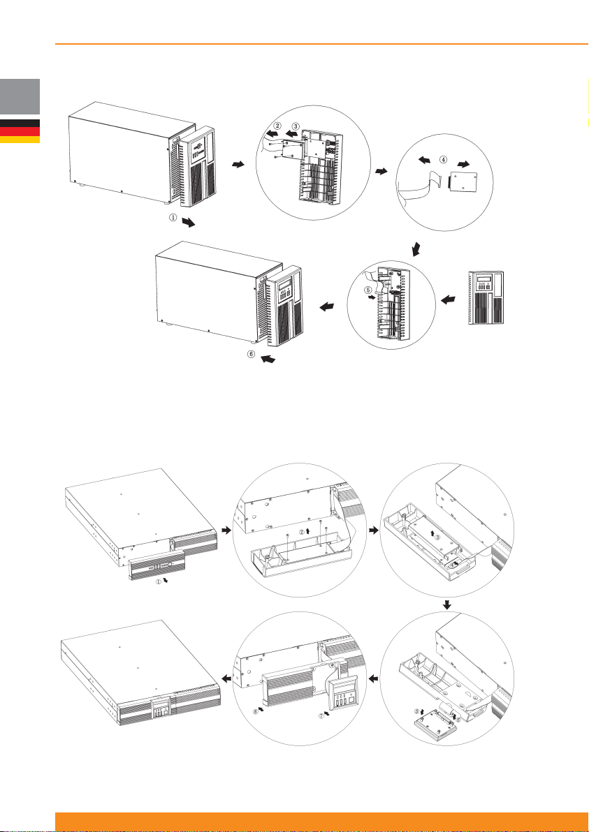
DE
Chloride Active
Tower Modelle
Rack/Tower Modelle
74
945044.066
Page 77
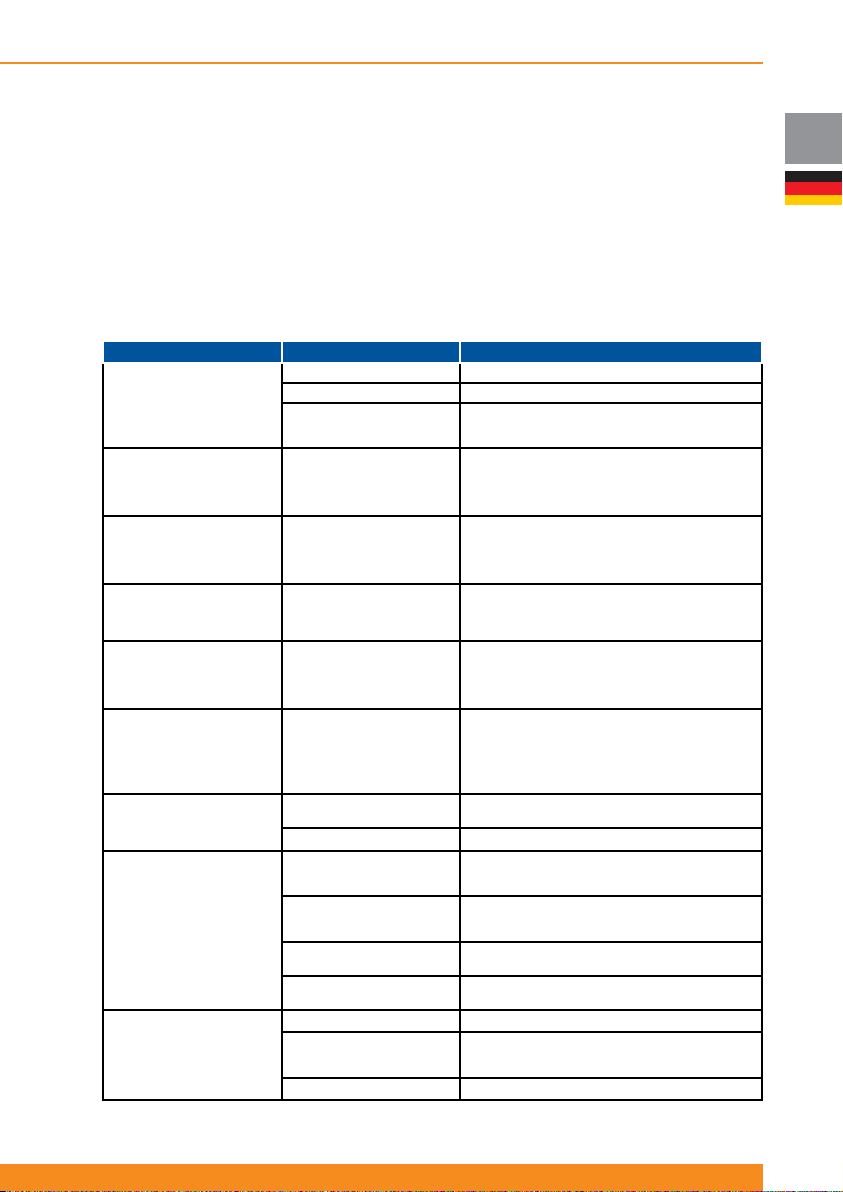
Chloride Active
7 Fehlerbehebung
Falls, trotz der hohen Zuverlässigkeit der Serie A, Probleme auftreten sollten, überprüfen Sie bitte die
folgenden Punkte, bevor Sie den zuständigen Kundendienst benachrichtigen:
- Liegt am Eingang der USV Netzspannung an?
- Ist die Eingangssicherung defekt oder wurden Schutzschalter ausgelöst?
Wenn Sie den zuständigen Kundendienst kontaktieren, halten Sie bitte folgende Informationen bereit:
- USV Informationen (Modell, Produkt-Code/MLFB, Serien-Nr. auf dem Typenschild)
- Eine möglichst genaue Beschreibung des Problems (welche Last wird betrieben, tritt das Problem
regelmässig oder sporadisch auf etc.?)
Sehen Sie bitte Abschnitt 4.2 für die Beschreibung der unten genannten Indikatoren.
Problem Mögliche Ursache Maßnahmen
Keine Anzeige
Kein Alarm
(USV ausgeschaltet)
AN-LED leuchtet nicht bei
anliegender Netzspannung,
akustischer Alarm in
Intervallen
USV Überlast LED blinkt/
kontinuierliches akustisches
Signal (oder LCD-Display
zeigt Überlast Meldung)
Last ausgefallen
Batteriefehler LED blinkt/
akustisches Signal in
Intervallen (oder LCD Display
zeigt Batteriefehler Meldung)
Batteriefehler
LED blinkt/akustisches
langes Signal einmal pro
Stunde
Erkennung: Verdrahtungsfehler
LED blinkt, Verdrahtungsfehler
A/D LED ist an,
kontinuierliches akustisches
Signal (oder LCD Display zeigt
Verdrahtungsfehler Meldung)
USV Fehler LED leuchtet/
kontinuierliches akustisches
Signal (oder LCD-Display
zeigt Fehlermeldung)
Autonomie geringer als
spezifi ziert
Keine Kommunikation
zwischen USV und PC
Hauptschalter ausgeschaltet Hauptschalter einschalten
Keine Netzspannung vorhanden
Eingangssicherung defekt
oder Eingangsschutzschalter
ausgelöst
Überlastung Warnung: USV
ist überlastet
(Einheit in Netzbetrieb)
Überlastungsfehler: USV ist
überlastet
(Einheit in Batterie-Betrieb)
Ein Batteriefehler wurde
während des automatischen
Batterietests festgestellt
Batterie hat Haltbarkeitszeit
erreicht, die
Überbrückungskapazität
der Batterie ist nicht mehr
zuverlässig
Phasenumkehrung (Phase
und Neutral) wurde am
Netzanschluss festgestellt
USV-Fehler
Überhitzung Setzen Sie die Umgebungstemperatur herab
Der Sicherungsschalter der
Batterieerweiterung ist in der
“OPEN”/OFFEN-Position
Batterien sind nicht voll
geladen
Batterien sind defekt
Lademodul ist defekt
Falsches serielles Kabel
Schnittstelle am PC ist von
einem anderen Prozess
belegt oder defekt
Interferenz am Datenkabel
Netz durch einen qualifi zierten Elektriker überprüfen lassen
Ersetzen Sie die Sicherung mit einer gleichen Typs oder
schalten Sie den Schutzschalter wieder ein. Wenn das Problem
anhält, kontaktieren Sie den zuständigen Kundendienst
Prüfen Sie die Leistung, die vom Equipment
gefordert wird und stecken Sie die Geräte mit
Kurzschluss oder geringerer Priorität aus
Prüfen Sie die Leistung, die vom Equipment
gefordert wird und stecken Geräte mit Kurzschluss
oder geringerer Priorität aus.
Starten Sie die USV erneut
Prüfen Sie, ob die Batterieanschlüsse richtig sitzen
Ersetzen Sie die Batteriemodule
Stellen Sie den Alarm zurück, indem Sie Taste 5 und
Prüfen Sie, ob das richtige Kabel angeschlossen wurde
Legen Sie das Kabel direkt/installieren Sie die Verkabelung neu
6 für 3 Sekunden betätigen
Ersetzen Sie die Batteriemodule
Ziehen Sie den Hauptstecker und stecken Sie ihn
Schalten Sie den Sicherungsschalter auf „ON“
Laden Sie die Batterien und testen Sie die
Überbrückungszeit. Wenn das Problem anhält,
kontaktieren Sie den zuständigen Kundendienst
Prüfen Sie, ob andere Programme auf die
Schnittstelle am PC zugreifen; wählen Sie eine
verdreht wieder ein
Bitte kontaktieren Sie den zuständigen
Bitte kontaktieren Sie den zuständigen
Bitte kontaktieren Sie den zuständigen
Kundendienst
Kundendienst
Kundendienst
andere serielle Schnittstelle
DE
75
Page 78
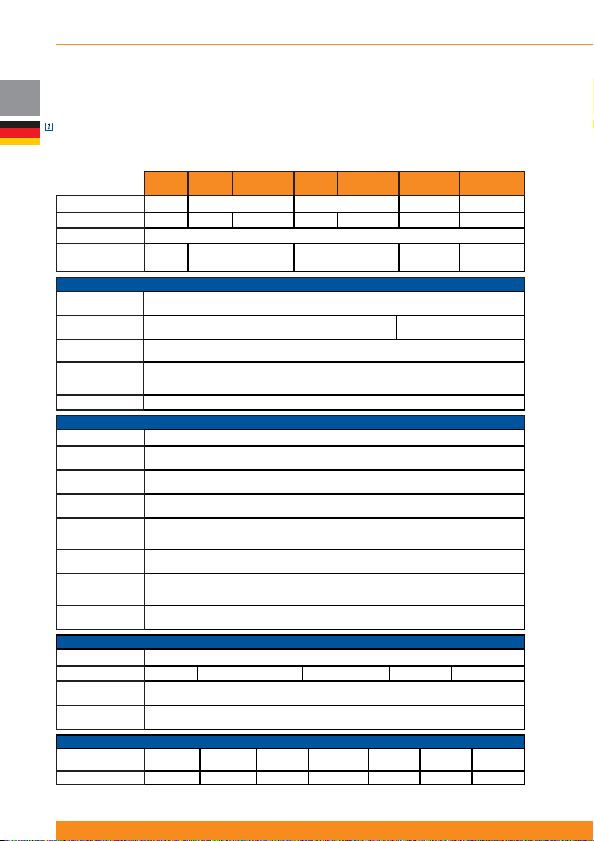
Chloride Active
DE
8 Spezifi kation und Backup Zeiten
8.1 Spezifi kation
ANMERKUNG: Wir behalten uns das Recht vor, die Informationen in diesen Tabellen ohne vorherigen
Hinweis zu ändern.
8.1.1 Unterbrechungsfreie Stromversorgungseinheiten
Active
USV Leistung 700VA 1000VA 1500VA 2000VA 3000VA
Gehäuse Tower Tower Rack/Tower Tower
USV-Klassifi zierung
Abgabeleistung
(VA/W)
Nominale
Eingangsspannung (VAC)
Eingangsspannungsbereich
(VAC)
Nominale
Eingangsfrequenz (Hz)
Eingangsfrequenzbereich
(Hz)
Faktor Leistungsaufnahme
Wellenform
Nominal
Ausgangsspannung (VAC)
Spannungsregulierung
(%)
Ausgangsfrequenz
(Hz)
Klirrfaktor (lineare/
nicht lineare Last)
THDv
Umschaltzeit (Netz-
Batterie-Netz) (s)
Überlastkapazität
(Netzbetrieb,
Ausgangsleistungsfaktor 0,9)
Kurzschluss
Sicherung
Typ
Blöcke 2x7,2Ah 3x7,2Ah 3x9Ah
Erweiterte
Batteriepfl ege
Batterie
Management
Dimensionen (BxHxT in mm)
Gewicht (kg) 13 15 18 18
700/630
157x245x438 157x245x438
76
Active
700 T
1000 T
120V-284V (abhängig von der Ausgangslast)
200(**) / 208(**) / 220 / 230 (voreingestellt) / 240 V (einstellbar über Software und optionalem
50/60Hz ±0,5% (wie Eingang oder auswählbar im Frequenzkonverter Modus)
<110% Warnung // /110% 130%: 12 Sekunden (USV nach Bypass) // >/130%: 1,5 Sekunden
Automatische Batteriepaket-Erkennung, automatische Berechnung Überbrückungszeit,
Active
1000 RT
1000/900(*) 1500/1350(*)
50/60Hz +/-5% (40/70Hz wenn Frequenzkonverter Modus aktiviert)
Verschlossene, wartungsfreie Bleiakkus (VRLA)
MECHANISCHE DATEN
Active
1500 T
VFI-SS-111 nach IEC 62040-3
EINGANG
50/60Hz Auto-Einstellung
0,99 (Batterien geladen)
AUSGANG
Reine Sinuswelle
LCD Display) (250 V auf Anfrage)
Max. 4% / Max. 8%
BATTERIEN
Tiefentladungsschutz
438x86
(2U)x482
Active
1500 RT
Rack/Tower Rack/Tower Rack/Tower
200-240V
3%
0
(USV aus)
Ja
Ja
157x245x488
Active
2000 RT
2000/1800(*)
140-284V (abhängig von der
Ausgangslast)
6x7,2Ah 6x9Ah
438x86
(2U)x482
20
438x86
(2U)x657
26 31
Active
3000 RT
3000/2700(*)
438x86
(2U)x657
945044.066
Page 79
Chloride Active
Bypass
Wirkungsgradim
Netzbetrieb (%)
Maximaler
Geräuschpegel im
Netzbetrieb bei 1 m
Abstand (dB)
Variable
Lüftergeschwindigkeit
Externe Batteriepacks
Farbe
serielle Schnittstellen 1xDB9 (RS232 und Kontakt-Signale), 1xUSB (***)
Kommunikationssteckplätze
Remote Power Off (RPO) Ja
Remote On/Off (ROO) Ja
Kontaktsignale
Betriebstemperatur 0 - 40 ºC
Lagertemperatur
Höhe 0-3000m
Relative Feuchtigkeit 10% to 90%
Eingang
Ausgang 6 x IEC320 C13 (10A), 3 von ihnen steuerbar (2 Gruppen)
CE Zeichen Ja
Sicherheit EN 62040-1, EN 60950 (RD), TÜV, CB Bericht, UL/cUL
EMC IEC62040-2, Klasse C2; IEC61000-4-3/3/4/5/6/8/11; VDE160; IEC61000-2-2
Leistung EN62040-3
86% 86% 86%
40
Nein
1x Steckplatz für SNMP/TCP-IP/Web Schnittstelle oder Karte mit potentialfreien Kontakten
Verfügbare opto-gekoppelte Signale, Open-Collector Signale an DB9 Port: Batterie
ALLGEMEIN
41 41 47 47
SCHNITTSTELLEN
schwach, Netzausfall, Bypass aktiv, SUM Alarm
UMGEBUNGSBEDINGUNGEN
-25 ºC / +50 ºC ohne Batterien, -15ºC/40ºC mit Batterien
ANSCHLÜSSE
1 x IEC320 C14 (10A)
STANDARDS
Ja (automatisch)
Ja
Ja
Anthrazit Grau (RAL7016)
als Zubehör
88% 90%
1 x IEC320
C20 (16A)
6 x IEC320
C13 (10A),
3 von ihnen
steuerbar (2
Gruppen)
1 x IEC320
C19 (16A)
(*) Ausgangsleistung mit externen Batteriepacks ist – 1000 VA Modelle: 1000 VA/800 W, 1500 VA Modelle:
1500 VA/1200 W, 2000 VA Modelle: 2000 VA/1600 W, 3000 VA Modelle: 3000 VA/2400 W.
(**) Bei nominaler Ausgangspannung 200 V ist die Leistung um 20% reduziert (die nominale Leistung der
Einheit ist um 20% reduziert). Bei nominaler Ausgangspannung 208 V ist die Leistung um 10% reduziert
(die nominale Leistung der Einheit ist um 10% reduziert).
(***) Beide Schnittstellen können nicht gleichzeitig benutzt werden.
DE
77
Page 80
DE
Chloride Active
8.1.2 Batteriepakete
BP-A1000/1500-T BP-A1000/1500-RT BP-A2000/3000-RT
Gehäuse
Batterie Zusammensetzung
Schutz
Tow e r
2x3x7,2Ah
Schutzschalte 70A/80Vdc
MECHANISCHE DATEN
Dimensionen (BxHxT in mm)
Gewicht (kg)
157x245x438
20
UMGEBUNGSBEDINGUNGEN
Betriebstemperatur 0 - 40 ºC
Lagertemperatur -15 ºC / +40 ºC
Höhe 0-3000m
Relative Feuchtigkeit 10% to 90%
ANMERKUNG: Das 700 VA-Modell hat keine externen Batteriepakete.
8.2 Laufzeit Diagramme
Theoretische Werte bei voll geladenen Batterien und resistiver Last.
ANMERKUNG: Es können maximal 4 externe Batteriepakete die an die USV angeschlossen werden.
Active 700 T:
Active 1000 T und Active 1000 RT:
Last USV
55W 51 min
110W 35 min
170W 24 min
225W 18 min
280W 15 min
335W 12 min
390W 10 min
450W 8 min
505W 7 min
560W 5 min
Rack/Tower Rack/Tower
2x3x7,2Ah 2x6x9Ah
Schutzschalte 70A/80Vdc Schutzschalte 70A/80Vdc
438x86(2U)x438 438x86(2U)x657
32 52
78
945044.066
Last USV
80W 63 min 239 min 438 min 661 min 861 min
160W 37 min 158 min 254 min 397 min 476 min
240W 26 min 91 min 197 min 262 min 372 min
320W 20 min 69 min 145 min 212 min 263 min
400W 15 min 55 min 97 min 174 min 220 min
480W 13 min 45 min 80 min 136 min 191 min
560W 11 min 38 min 69 min 99 min 161 min
640W
720W 7 min 29 min 51 min 75 min 99 min
800W 6 min 25 min 46 min 67 min 89 min
9 min 33 min 60 min 86 min 130 min
USV
+ 1 BP
USV
+ 2 BP
USV
+ 3 BP
USV
+ 4 BP
Page 81
Active 1500 T und Active 1500RT:
Last USV
120W 42 min 170 min 268 min 409 min 497 min
240W 25 min 84 min 180 min 234 min 331 min
360W 17 min 58 min 108 min 183 min 225 min
480W 13 min 44 min 78 min 129 min 183 min
600W 10 min 34 min 62 min 90 min 140 min
720W 8 min 26 min 51 min 74 min 98 min
840W 7 min 24 min 43 min 63 min 83 min
960W
1080W 4 min 18 min 32 min 48 min 64 min
1200W 3 min 16 min 28 min 42min 56 min
Active 2000 RT:
USV
+ 1 BP
5 min 21 min 37 min 55 min 72 min
USV
+ 2 BP
USV
+ 3 BP
USV
+ 4 BP
Chloride Active
DE
Active 3000 RT:
Last USV
160W 63 min 231 min 406 min 558 min 754 min
320W 37 min 163 min 236 min 358 min 445 min
480W 26 min 97 min 195 min 237 min 327 min
640W 19 min 73 min 153 min 207 min 237 min
800W 15 min 58 min 108 min 177 min 213 min
960W 13 min 48 min 86 min 146 min 190 min
1120W 11 min 40 min 73 min 114 min 166 min
1280W
1440W 7 min 30 min 55 min 81 min 116 min
1600W 6 min 27 min 49 min 71 min 96 min
Last USV
240W 42 min 173 min 238 min 371 min 456 min
480W 26 min 90 min 182 min 226 min 282 min
720W 18 min 62 min 123 min 185 min 218 min
960W 14 min 47 min 84 min 141 min 185 min
1200W 11 min 37 min 66 min 98 min 150 min
1440W 8 min 31 min 55 min 80 min 115 min
1680W 7 min 26 min 47 min 68 min 92 min
1920W
2160W 4 min 20 min 35 min 52 min 68 min
2400W 3 min 18 min 31 min 46 min 60 min
9 min 35 min 63 min 93 min 142 min
5 min 23 min 40 min 59 min 78 min
USV
+ 1 BP
USV
+ 1 BP
USV
+ 2 BP
USV
+ 2 BP
USV
+ 3 BP
USV
+ 3 BP
USV
+ 4 BP
USV
+ 4 BP
79
Page 82

Chloride Active
1. Seguridad
E
1.1 Uso del equipo
1.2 Advertencias generales
1.3 Indicaciones de seguridad
1.4 Baterías y seguridad
1.5 Consideraciones medioambientales
1.6 Indicaciones sobre la declaración de conformidad CE
1.7 Reembalaje del equipo
2. Acerca de este manual
2.1 Introducción
2.2 Índice de equipos
2.3 Símbolos
2.4 Estructura de la documentación
3. Montaje e Instalación
3.1 Entrega
3.2 Desembalaje
3.3 Contenido
3.3.1 Equipos torre (SAI)
3.3.2 Equipos torre (Packs de baterías)
3.3.3 Equipos rack/torre (SAI)
3.3.4 quipos rack/torre (Packs de baterías)
3.4 Almacenamiento
3.5 Manipulación
3.6 Condiciones ambientales
3.7 Carga sobre el suelo
3.8 Carga en el rack
3.9 Ventilación
3.10 Datos de instalación
3.11 Montaje en rack del SAI o packs de baterías (sólo modelos RT)
3.12 Montaje en torre del SAI o packs de baterías (sólo modelos RT)
3.12.1 Montaje del SAI
3.12.2 Montaje del SAI con un pack de baterías
4. Puesta en marcha y funcionamiento
4.1 Teoría de funcionamiento
4.1.1 Modo línea
4.1.2 Modo baterías
4.1.3 Modo bypass
4.1.4 Modo ECO
4.1.5 Modo convertidor de frecuencia
4.1.6 Otros detalles de funcionamiento
4.1.7 Diagrama de bloques
4.2 Indicadores del panel frontal y descripción de sus elementos
4.2.1 Equipos con indicadores LED
4.2.1.1 Descripción de los elementos
4.2.1.2 Operación
4.2.1.3 Indicadores
4.2.2 Equipos con Display LCD
4.2.2.1 Menús y funcionalidades
4.2.2.2 Mensajes de advertencia y fallo
4.3 Panel trasero de los equipos
4.3.1 Equipos torre
82
82
82
82
83
84
84
84
85
85
85
86
86
87
87
87
87
87
87
87
88
88
88
88
89
89
89
89
89
91
91
91
92
92
92
92
92
92
92
93
93
94
94
94
95
96
97
100
100
100
80
945044.066
Page 83

Chloride Active
4.3.2 Equipos rack/torre
4.4 Puesta en marcha y apagado
4.4.1 Preparaciones eléctricas
4.4.2 Conexiones
4.4.2.1 Conexiones de packs de baterías externos
4.4.2.2 Conexiones de potencia
4.4.3 Procedimiento de arranque
4.4.3.1 Procedimiento de arranque inicial
4.4.3.2 Procedimiento de arranque normal
4.4.4 Procedimiento de bypass forzado
4.4.5 Procedimiento de activación/desactivación del modo ECO
4.4.6 Procedimiento de activación/desactivación del modo convertidor de frecuencia
4.4.7 Procedimiento de apagado del SAI
4.4.8 Apagado remoto (RPO) y Apagado/encendido remoto (ROO)
5. Interfaces de comunicación
5.1 Interfaz serie
5.2 Puerto DB9
5.3 Puerto USB
5.4 Slot de comunicaciones
6. Mantenimiento
6.1 Limpieza
6.2 Almacenamiento del SAI
6.3 Test de baterías
6.4 Cambio de baterías
6.4.1 Cambio de las baterías internas del SAI
6.4.2 Tratamiento de las baterías usadas
6.5 Instalación del panel frontal con Display LCD
7. Tratamiento de problemas
8. Datos técnicos
8.1 Especifi cación técnica
8.1.1 Sistema de alimentación ininterrumpida (SAI)
8.1.2 Packs de baterías
8.2 Autonomías típicas
102
103
103
103
103
104
104
104
105
105
105
106
106
106
107
107
107
108
108
109
109
109
109
109
109
111
111
113
114
114
114
116
116
E
81
Page 84

Chloride Active
1. Seguridad
E
1.1 Uso del equipo
Este equipo funciona como un Sistema de Alimentación Ininterrumpida (SAI) para las cargas conectadas. El
equipo cumple todas las prescripciones de seguridad pertinentes relativas a equipamiento de tecnología de
la información, para uso en entornos de ofi cinas.
Dependiendo del tipo y potencia del SAI, ciertas confi guraciones de extensiones de baterías se pueden conectar
al equipo. Estos packs de baterías sólo se pueden conectar a un SAI compatible con los mismos.
1.2 Advertencias generales
ADVERTENCIA: Damos la máxima importancia a la seguridad de las personas. Por esta razón, es esencial
que los procedimientos relativos a la seguridad incluidos en este manual sean atentamente revisados antes
de comenzar a trabajar, y adecuadamente observados en lo sucesivo. El usuario puede tomar parte en el
funcionamiento del SAI si las instrucciones mostradas en el capítulo 3 (“Montaje e Instalación”) son respetadas
estrictamente.
ADVERTENCIA: Incluso cuando todos los interruptores están abiertos, existen tensiones peligrosas dentro
del equipo. No hay elementos que puedan ser reparados por el usuario dentro del mismo. Solamente personal
autorizado puede llevar a cabo cualquier operación que requiera abrir o quitar los paneles y cubiertas del
equipo. Cualquier reparación o modifi cación efectuada por el usuario puede ocasionar reparaciones fuera de
garantía, condiciones eléctricas peligrosas o violación de los códigos eléctricos.
ADVERTENCIA: Con el fi n de cumplir los requerimientos de UL, debe haber un dispositivo de desconexión a
la salida del SAI (nota: el conector de salida puede ser considerado como un dispositivo de desconexión)
ADVERTENCIA: Con el fi n de cumplir los requerimientos de UL, para reducir el riesgo de fuego, conecte la
entrada del SAI solo a un circuito con protección de sobrecorriente de 20 Amperios de acuerdo con el Código
Eléctrico Nacional ANSI/NFPA 70.
1.3 Indicaciones de seguridad
ADVERTENCIA: : Lea las siguientes indicaciones de seguridad atentamente. No tener en cuenta estas
indicaciones puede poner en peligro su vida, su salud, la fi abilidad de su equipo y la seguridad de sus
datos.
- Transporte el equipo sólo en embalajes adecuados (protegidos frente a impactos y sacudidas).
- Si el SAI se transporta de un entorno frío a un lugar de funcionamiento más templado, puede existir
condensación. Antes de encender el SAI, éste debe estar completamente seco. Un periodo de aclimatación
de al menos dos horas es necesario.
- El SAI debe ser instalado de acuerdo con las condiciones ambientales especifi cadas en los capítulos 3.6
y 3.10.
- Incluso con todos los botones en posición “OFF” el equipo (SAI) no está aislado de la red eléctrica. Para
aislarlo completamente de la red, el cable de entrada debe ser desconectado.
- Este equipo toma energía desde más de una fuente. Los conectores de salida y/o entrada pueden tener
tensión incluso cuando el equipo está desenchufado. Los SAIs presentan una problemática de seguridad
diferente a la de otros equipos eléctricos, ya que se ponen en modo batería si son desenchufados. Desenchufar
el equipo no elimina la carga eléctrica.
- En caso de interrupción de la red eléctrica, las baterías integradas en el equipo mantienen el suministro de
energía al equipamiento del usuario.
- Sitúe los cables de modo que nadie pueda pisarlos o tropezarse con ellos. Cuando conecte el equipo a la
red eléctrica, siga las instrucciones del capítulo 3 (“Montaje e Instalación”).
- Asegúrese de que ningún objeto (collares, clips, etc) entra en el equipo.
- En emergencias (por ejemplo: daños en la cubierta, en los elementos de mando o cables, penetración de
líquidos o cuerpos extraños) apague el equipo, desconéctelo de la red y contacte con el servicio técnico
autorizado.
- No conecte al SAI cargas que lo sobrecarguen o demanden corriente continua.
- Cuando limpie el equipo, siga las instrucciones del capítulo 6 (“Mantenimiento”).
82
945044.066
Page 85

Chloride Active
- Las líneas de transmisión de datos no se deben conectar o desconectar durante tormentas.
- La suma de las corrientes de fuga (corrientes en el conductor de tierra) del SAI y las cargas conectadas no
debe superar el valor de 3.5 mA.
- Los terminales RPO (Remote Power Off – Apagado Remoto) y ROO (Remote On Off – Apagado y Encendido
Remoto) están situados en la parte trasera del equipo (véase 4.4.8). Cuando las conexiones adecuadas están
abiertas, la circuitería de control inmediatamente corta la salida del SAI.
- Cuando instale los equipos en racks, no sitúe los elementos más pesados en la parte superior. Instale
los equipos más pesados (típicamente el SAI y las baterías) cerca de la parte inferior antes de instalar otro
equipamiento en las zonas superiores del rack.
- Este equipo está equipado con un cable de red de seguridad comprobada, y debe ser conectado sólo a una
toma de corriente con contacto de protección que esté puesto a tierra.
- Asegúrese de que la toma de corriente del equipo, o la toma de corriente con contacto de protección de la
instalación doméstica, están accesibles sin impedimentos.
- Éste es un producto SAI de categoría C2. En un entorno residencial este producto puede causar radiointerferencias, en cuyo caso el usuario puede necesitar tomar medidas adicionales.
1.4 Baterías y seguridad
ADVERTENCIA: Las baterías instaladas en el SAI y en los packs de baterías contienen electrolito. Bajo
condiciones normales, las carcasas de las baterías están secas. Una batería dañada puede derramar electrolito
que puede ser peligroso en contacto con la piel y causar irritación en los ojos. Si esto ocurre, aclare la zona
afectada con abundante agua y busque ayuda médica inmediatamente.
- Siempre hay tensión presente en los terminales de las baterías.
- Incluso cuando está descargada, una batería tiene capacidad para suministrar una alta corriente de
cortocircuito que, además de causar daños a las propias baterías y cableado asociado, puede exponer al
operario a riesgo de quemaduras.
- Las baterías no deben mantenerse almacenadas por periodos superiores a 6 meses a 25ºC sin ser recargadas
(habiendo sido recargadas al 100% al comienzo de dicho periodo). Si estas condiciones no son respetadas,
el funcionamiento de las baterías no puede ser garantizado. Es recomendable recargar las baterías al menos
una vez cada 4 meses.
- Dado que las baterías nuevas no dan su capacidad total después de una carga inicial, puede ser necesario
efectuar un número de ciclos de carga/descarga antes de que se alcance el rendimiento óptimo.
- Con el fi n de proteger el medioambiente, las baterías deben ser eliminadas de acuerdo con la legislación
vigente relativa a eliminación/reciclado de residuos tóxicos.
Para el cambio de baterías en una zona de acceso de servicio:
- El cambio de baterías debe ser realizado por personal cualifi cado en materia de baterías y medidas de
seguridad correspondientes.
- Las baterías instaladas dentro del SAI y de los armarios de baterías contienen electrolito.
En condiciones normales de uso, las carcasas de las baterías están secas. Una batería dañada puede derramar
electrolito que puede ser peligroso en contacto con la piel y causar irritación en los ojos. Si esto ocurre, aclare
la zona afectada con abundante agua y busque ayuda médica inmediatamente.
- Cuando se cambien las baterías, deben reemplazarse por el mismo tipo y número de baterías o packs
de baterías
- No tirar las baterías al fuego. Las baterías pueden explotar.
- No abrir o dañar las baterías. El electrolito liberado es perjudicial para la piel y los ojos y puede ser tóxico.
- Una batería puede presentar riesgo de shock eléctrico y de cortocircuito. Se deberán tomar las siguientes
precauciones cuando se trabaje con baterías:
Retirar relojes, anillos o cualquier otro tipo de objetos metálicos.
Utilizar herramientas aisladas.
Utilizar guantes y botas de caucho.
No dejar herramientas o piezas metálicas encima de las baterías.
Desconectar la fuente de carga antes de conectar o desconectar los terminales de las baterías
Determinar si las baterías están inadvertidamente puestas a tierra. En ese caso, eliminar la conexión
a tierra. El contacto con algún componente de una batería puesta a tierra puede resultar en shock
eléctrico. La probabilidad de dicho shock se reduce si las tierras son eliminadas durante las operaciones
de instalación y mantenimiento (aplicable a equipamiento y fuentes remotas de baterías que no tienen
un circuito de alimentación puesto a tierra)
E
83
Page 86

Chloride Active
1.5 Consideraciones medioambientales
E
Este equipo contiene baterías. Su eliminación debe respetar lo establecido a este respecto por la legislación
vigente en su país.
El plomo y el ácido que contienen pueden causar graves daños al medioambiente.
Los equipos deberán eliminarse al fi nal de su vida útil según lo establecido por la legislación de su país.
Incorporamos como parte del diseño de nuestros equipos aspectos medioambientales, buscando reducir al
mínimo el impacto medioambiental de los mismos. Esto signifi ca incorporar aquellos avances técnicos que
permitan reducir al máximo la utilización de sustancias nocivas y peligrosas y la generación de residuos
tóxicos y peligrosos.
Este manual incluye recomendaciones de uso pensadas para optimizar el funcionamiento de su equipo y
de sus componentes.
1.6 Indicaciones sobre la declaración de conformidad CE
Este equipo cumple las prescripciones de las siguientes directivas europeas:
73/23/EWG. Directiva del Consejo para la adaptación de los reglamentos legales de los estados miembros
en lo concerniente a equipos eléctricos de utilización dentro de límites de tensión determinados, modifi cado
mediante 93/68/CEE.
89/336/EWG. Directiva del Consejo para la adaptación de los reglamentos legales de los estados miembros
en lo concerniente a la protección contra campos electromagnéticos, modifi cado mediante 91/263/CEE,
92/31/CEE y 93/68/CEE.
La observancia de estas directivas se comprueba a través del cumplimiento de las siguientes normas:
- EN 62040-1-1
- EN 62040-2
En los anexos DBT y CEM de la declaración de conformidad CE se incluyen más informaciones sobre el
cumplimiento de estas directivas.
En caso de necesidad, se puede solicitar la declaración de conformidad CE al fabricante.
1.7 Reembalaje del equipo
No empaquete los equipos hasta que hayan pasado al menos dos horas desde la última recarga.
Aloje el equipo en bolsas hechas de un material lo sufi cientemente poroso como para que pueda respirar
(por ejemplo, polietileno de 100μm).
No elimine el aire del embalaje.
Cuando embale el equipo para transporte a través de empresa de transportes común, sitúe el equipo en el
embalaje original o equivalente.
84
945044.066
Page 87
Chloride Active
2 Acerca de este manual
2.1 Introducción
Este manual contiene información acerca de la instalación, operación y uso de este Sistema de Alimentación
Ininterrumpida (SAI).
Consulte este manual antes de instalar el equipo. Este manual se debe guardar para posteriores consultas
relativas al funcionamiento y mantenimiento del SAI.
2.2 Índice de equipos
Estos SAIs están disponibles con varias potencias nominales y en varias confi guraciones físicas.
La siguiente tabla muestra las diferentes versiones del equipo.
Dependiendo de cada mercado local, estos equipos pueden incluir un panel frontal con indicadores LED o
un panel frontal con Display LCD.
Para los equipos con panel frontal con indicadores LED, existen paneles frontales con Display LCD disponibles
como accesorio. Estos paneles frontales han de ser pedidos por separado. La instalación del panel frontal
con Display LCD debe ser llevada a cabo por técnicos cualifi cados. Por favor, contacte con el servicio técnico
autorizado. Para más detalles acerca de la instalación, véase el capítulo 6.5
Confi guración Designación
Tor re
Rack/Torre convertible
(puede montarse en rack o
como torre)
Potencia nominal
Active 700 T 700 VA
Active 1000 T 1000 VA
Active 1500 T 1500 VA
Active 1000 RT 1000 VA
Active 1500 RT 1500 VA
Active 2000 RT 2000 VA
Active 3000 RT 3000 VA
E
Los siguientes packs de baterías están disponibles:
Confi guración Designación SAI compatible
Torre
Rack/Torre convertible
(puede montarse en rack o
como torre)
BP-A1000/1500 T
BP-A1000/1500 RT
BP-A2000/3000 RT
Active 1000 T
Active 1500 T
Active 1000 RT
Active 1500 RT
Active 2000 RT
Active 3000 RT
85
Page 88

Chloride Active
2.3 Símbolos
E
ATENCIÓN: Indica instrucciones que, en caso de no ser cumplidas, pueden poner en peligro la fi abilidad de
su SAI o la seguridad de sus datos
ADVERTENCIA: Indica instrucciones que, en caso de no ser cumplidas, presentan riesgo de shock eléctrico,
pueden poner en peligro su vida, su salud, la fi abilidad de su SAI o la seguridad de sus datos.
NOTA: Indica instrucciones y comentarios que dan más detalles acerca del SAI y complementan el texto
principal.
2.4 Estructura de la documentación
Estas instrucciones pueden ser complementadas con hojas anexas que describan determinadas ampliaciones
u opciones, por ejemplo.
86
945044.066
Page 89
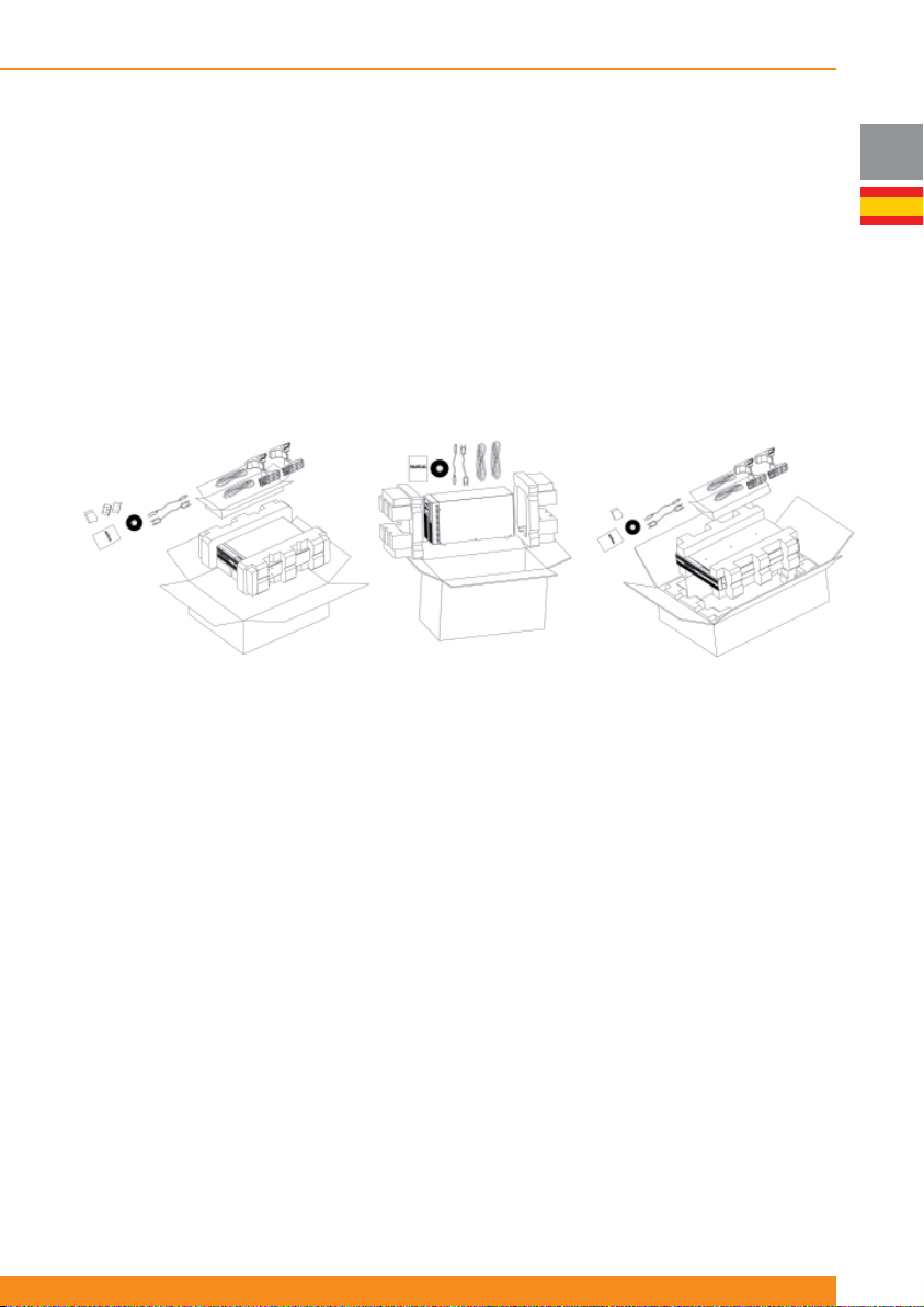
Chloride Active
3 Montaje e Instalación
3.1 Entrega
Este equipo ha sido chequeado minuciosamente antes de ser servido. Cuando lo reciba, compruebe el
embalaje y asegúrese de que el contenido no está dañado. Cualquier daño debe ser reportado al transportista
y cualquier elemento que falte debe ser reportado al suministrador inmediatamente.
3.2 Desembalaje
El equipo debe ser desembalado cuidadosamente para evitar daños en el equipo. Compruebe todos los
materiales incluidos en el embalaje para asegurarse de que no falta ninguno (véanse las fi guras de abajo).
Nótese que dichas fi guras son simplemente descriptivas y su contenido está sujeto a cambios de acuerdo
a los mercados locales.
Equipos rack/torre 1 y 1.5kVA
Equipos torre
3.3 Contenido
Los siguientes elementos se incluyen con el equipo.
3.3.1 Equipos torre (SAI)
- 1 x este manual de usuario
- 1 x SAI
- 1 x guía quickstart
- 1 x CD con software de usuario
- 2 x cable de conexión IEC320 C14 (macho) – IEC320 C13 (hembra) para la salida del SAI
- 1 x cable de interfaz RS232
- 1 x cable USB
Equipos rack/torre 2 y 3kVA
E
3.3.2 Equipos torre (Packs de baterías)
- 1 x Pack de baterías
- 1 x cable de extensión de baterías
- 1 x cable de auto-detección del número de packs de baterías conectados
3.3.3 Equipos Rack/Torre (SAI)
- 1 x este manual de usuario
- 1 x SAI
- 1 x guía quickstart
- 1 x CD con software de usuario
- Cables según modelos como sigue:
87
Page 90
Chloride Active
E
- 1 x cable de interfaz RS232
- 1 x cable USB
- 2 x piezas auxiliares para montaje en rack con tornillería
- 2 x juegos de piezas (pies) para montaje en torre
- 2 x raíles para montaje en rack (opcionalmente) con tornillería
Modelos de 1000, 1500 y 2000VA
2 x cable de conexión IEC320 C14
(macho) – IEC320 C13 (hembra)
para la salida del SAI
Modelos de 3000VA
1 x cable de conexión Schuko
(macho) - IEC320 C19 (hembra)
para la entrada del SAI
1 x base múltiple IEC230 C20
(macho) – 3 x Schuko (hembra)
para la salida del SAI
3.3.4 Equipos Rack/Torre (Packs de baterías)
- 1 x Pack de baterías
- 1 x cable de extensión de baterías
- 1 x cable de auto-detección del número de packs de baterías conectados
- 2 x piezas auxiliares para montaje en rack con tornillería
- 2 x piezas espaciadoras para ensamblar los juegos de piezas (pies) para montaje en torre
- 1 x chapa para unir SAI y pack de baterías para montaje en torre
- 2 x raíles para montaje en rack (opcionalmente) con tornillería
3.4 Almacenamiento
Si no se pretende que el SAI sea usado dentro de los siete días siguientes a la entrega, se debe prestar
atención a las condiciones de almacenamiento.
El SAI debe ser almacenado en un entorno limpio y seco y lejos de temperaturas extremas. Se recomienda
que el equipo se almacene en un entorno de temperatura controlada y moderada humedad. La siguiente
tabla muestra los límites de temperatura y humedad de almacenamiento:
Límites de temperatura
Humedad relativa (sin
condensación)
-25ºC/50ºC (sin baterías)
-15ºC/40ºC (con baterías)
10-90%
3.5 Manipulación
El SAI debe mantenerse derecho todo el tiempo y debe ser manipulado con cuidado. El equipo se puede
dañar si se cae o recibe un fuerte impacto.
3.6 Condiciones ambientales
El SAI versión torre debe ser instalado verticalmente. El SAI versión rack/torre (RT a partir de ahora) puede
ser instalado verticalmente u horizontalmente, dependiendo de la aplicación deseada.
En cualquier caso, debe ser instalado en una superfi cie plana y nivelada y en un área protegida de
temperaturas extremas, agua, humedad y la presencia de polvo o partículas (véase el capítulo 3.10). No
apile los equipos y no ponga objetos encima de los mismos.
El rango de temperatura de funcionamiento del SAI se especifi ca en el capítulo 8 (“Especifi caciones
técnicas”).
El rango ideal de temperatura ambiente es de 15ºC a 25ºC.
Los tiempos de autonomía estimados y el tiempo de vida de las baterías están defi nidos a 20ºC. Los
incrementos de temperatura por encima de 25ºC reducen el tiempo de vida esperado de las baterías.
88
945044.066
Page 91
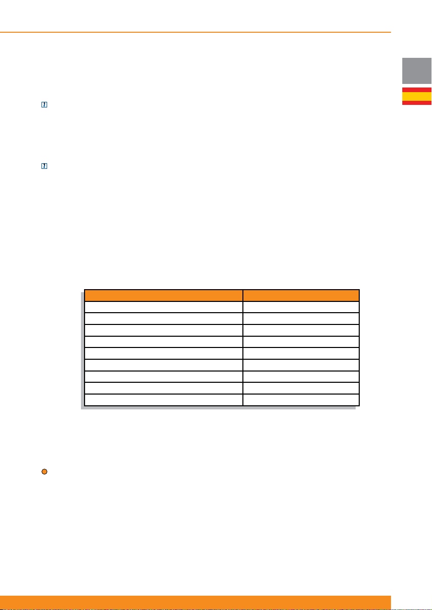
Chloride Active
3.7 Carga sobre el suelo
Considerando el peso del SAI y los packs de baterías de los modelos torre o RT montados como torre, es
necesario que el suelo de la ubicación elegida sea capaz de soportar el peso de los equipos.
NOTA: pesos de los SAIs y packs de baterías se muestran en el capítulo 8 (“datos técnicos”).
3.8 Carga en el rack
Considerando el peso del SAI y los packs de baterías de los modelos RT que pueden ser montados en un
rack, es necesario que el bastidor elegido sea capaz de soportar el peso de los equipos.
NOTA: Los pesos de los SAIs y packs de baterías se muestran en el capítulo 8 (“Especifi caciones
técnicas”).
3.9 Ventilación
Es necesario dejar un espacio de cómo mínimo 50mm en la parte trasera y delantera del SAI para permitir
el fl ujo de aire.
Las labores de mantenimiento eléctrico y reparación requieren acceso a la parte delantera y trasera del
SAI. Deje el espacio necesario para permitir al personal de servicio el acceso a los equipos.
3.10 Datos de instalación
Característica Especifi cación
Temperatura ambiente 0ºC a 40ºC
Humedad relativa (sin condensación) 20%-90%
Entorno Controlado (ofi cina o similar)
Máxima altitud (sin de-rating) 3.000 metros
Conexión de potencia de entrada Trasera
Conexión de potencia de salida Trasera
Conexión de baterías externas Trasera
Entrada de aire Frontal
Salida de aire Trasera
E
3.11
Montaje en rack del SAI o packs de baterías (sólo modelos RT)
Los SAIs y packs de baterías RT se pueden montar en bastidores de cuatro perfi les. El SAI y los packs de
baterías externos usan los mismos elementos de montaje y el procedimiento para montarlos es el mismo.
ATENCIÓN: El SAI toma aire por el frontal. Si el bastidor rack tiene una puerta frontal, asegúrese de que
hay sufi ciente espacio entre la puerta y el frontal
Debido al peso y dimensiones de estos equipos (particularmente los modelos de 2 y 3kVA), se recomienda
que dos personas eleven el equipo para montarlo en el rack. Si sólo una persona está disponible, se
pueden desconectar y sacar las baterías internas del SAI, montar en el rack el SAI sin baterías (menos
peso) y re-conectar las baterías internas una vez que el SAI está en el rack.
Por favor, use sólo los elementos suministrados con el equipo para unir las piezas auxiliares al SAI o packs
de baterías externos.
89
Page 92
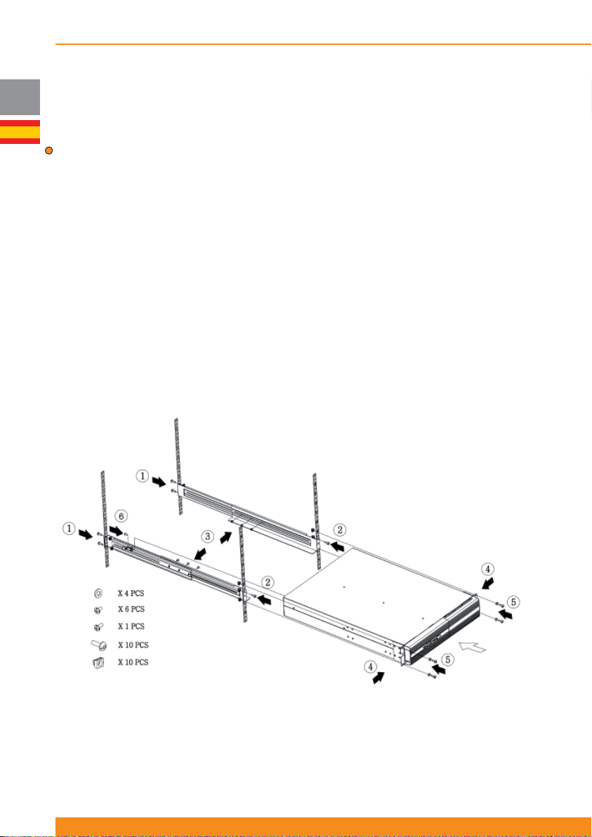
Chloride Active
Si su instalación incluye packs de baterías externos, móntelos primero y en la posición más baja posible
dentro del rack. Empiece en la posición más baja posible y vaya instalando el resto de equipos en las
E
posiciones superiores. El SAI debe ser montado en último lugar en una posición superior a los packs de
baterías para un cableado adecuado.
ATENCIÓN: Use todos los elementos de montaje suministrados con el SAI y packs de baterías. NUNCA
utilice equipos montados en una posición inferior para sostener a los equipos montados encima.
Todos los materiales de montaje para instalar el SAI en un rack están disponibles (incluidos con el equipo
o como accesorios). Para preparar el SAI y los packs de baterías externos para su uso en confi guración en
rack, primero instale los raíles (accesorio opcional) y luego instale el SAI y los packs de baterías siguiendo
los siguientes pasos:
1. Fije la parte trasera de los raíles a la parte trasera del rack con los dos tornillos suministrados
2. Fije la parte delantera de los raíles a la parte delantera del rack con el tornillo suministrado
3. Ensamble los raíles y fíjelos con los tres tornillos suministrados
4. Fije las dos piezas auxiliares a ambos lados del equipo con cuatro tornillos en cada lado
5. Deslice el equipo hasta su posición en el rack y fíjelo con dos tornillos en cada lado
6. Atornille el rail a la parte trasera del SAI (punto de fi jación para transporte seguro)
7. Repita estos pasos para cada SAI o pack de baterías que se vaya a montar
Una vez que la instalación mecánica se ha completado, por favor lea el capítulo 4 para una adecuada
puesta en marcha y operación del sistema.
90
945044.066
Page 93
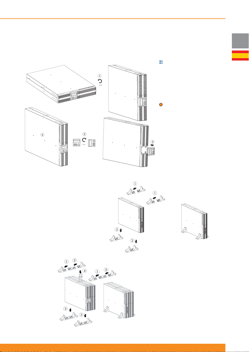
Chloride Active
3.12
Montaje en torre del SAI o packs de baterías (sólo modelos RT)
Los SAIs y packs de baterías RT están diseñados para ser montados en torre como alternativa al montaje
en rack.
NOTA: (sólo para unidades con
panel frontal con Display LCD).
El Display LCD se puede rotar
hasta la posición apropiada
cuando está montado en torre,
como se ilustra en la siguiente
fi gura.
ATENCIÓN: Use todos
los elementos de montaje
suministrados con el SAI y packs
de baterías
Una vez que la instalación
mecánica se ha completado, por
favor lea el capítulo 4 para una
adecuada puesta en marcha y
operación del sistema.
3.12.1 Montaje del SAI
E
Ensamble los dos juegos de
piezas (pies) para montaje en
torre suministrados con el equipo
y sitúe el SAI entre ellos como
muestran las siguientes fi guras
3.12.2 Montaje del SAI
con un pack de baterías
externo
Ensamble los dos juegos de
piezas (pies) suministrados
con el SAI con las piezas
espaciadoras suministradas
con el pack de baterías como
muestran las siguientes fi guras.
Luego fi je el SAI y el pack de
baterías con la chapa y los
tornillos suministrados.
91
Page 94

Chloride Active
4 Puesta en marcha y funcionamiento
E
4.1 Teoría de funcionamiento
ATENCIÓN: Este SAI se suministra con cables estándar de potencia y conectores adecuados para el uso
en su área de operación. Puede ser instalado y operado por personal no técnico
4.1.1 Modo Línea
En este modo, el SAI está conectado entre la entrada de red (AC) y la carga. El funcionamiento del SAI
se basa en el principio de doble conversión on-line en el cual la entrada de red se convierte primero
a corriente continua (CC), y posteriormente se convierte de nuevo a una forma de onda sinusoidal de
frecuencia y tensión fi jas para suministrar potencia de forma controlada a la carga. Esta topología de SAI
se usa para aislar la carga crítica de una variedad de problemas en la red eléctrica, incluyendo la pérdida
total de alimentación de red (corte o fallo de red).
4.1.2 Modo Baterías
En caso de un fallo de red, las baterías (libres de mantenimiento) continuarán suministrando energía
ininterrumpida a la carga. En la práctica, la mayoría de fallos de red son de corta duración. Por ello, la
energía almacenada en las baterías del SAI es en la mayoría de los casos sufi ciente para asegurar el
funcionamiento continuo de las cargas conectadas hasta que la red eléctrica se restablece. En caso de un
fallo de red prolongado, el SAI puede utilizarse con el software disponible para el cierre controlado de las
cargas conectadas.
El método más fi able para determinar la autonomía estimada de las baterías es el Display LCD o la
aplicación del software de usuario o la tarjeta SNMP. Con este software, la capacidad restante estimada de
las baterías se indica antes y durante el fallo de red. Estos productos permiten también procedimientos de
cierre automatizados que pueden apagar los dispositivos conectados después de cerrar de forma segura
programas, aplicaciones y el sistema operativo. Cuando vuelve la red, el SAI restablece automáticamente
el suministro a la carga e inicia la recarga de las baterías.
4.1.3 Modo Bypass
Si el SAI está en modo bypass, la carga es alimentada directamente desde la red de entrada a través del
bypass automático interno.
El equipo arranca automáticamente en bypass cuando se le conecta a la red de entrada, suministrando
tensión inmediatamente a la carga. Es necesario pulsar el botón de Inversor ON para arrancar el inversor y
pasar el equipo a modo línea (operación normal).
En caso de una sobrecarga o un fallo interno del SAI, la carga se alimenta inmediatamente de forma
directa desde la red de entrada a través de este bypass interno automático. En cuanto las condiciones
normales de red se restablecen, se realiza una conmutación automática al inversor.
Alternativamente, el equipo puede ser forzado a bypass mediante las teclas del panel frontal o el Display
LCD. En este caso, si los parámetros de entrada (tensión, frecuencia) salen de tolerancias, el equipo se
apaga automáticamente.
4.1.4 Modo ECO
Cuando el modo ECO está habilitado y las condiciones de la red están dentro de tolerancias, la salida
se alimenta de forma directa desde la entrada a través del bypass interno, consiguiendo de esta forma
altos valores de rendimiento y por tanto ahorrando energía. Cuando el modo ECO está activado y las
condiciones de red salen de tolerancias, el equipo alimenta automáticamente la carga desde el inversor
para mantenerla protegida.
Cuando el equipo funciona en modo ECO, el cargador interno de baterías está trabajando. Por ello, las
baterías se mantienen cargadas.
Para detalles acerca de cómo habilitar/deshabilitar este modo de operación, véase 4.4.5.
4.1.5 Modo Convertidor de Frecuencia
Cuando el modo ECO está habilitado y las condiciones de la red están dentro de tolerancias, la salida
se alimenta de forma directa desde la entrada a través del bypass interno, consiguiendo de esta forma
altos valores de rendimiento y por tanto ahorrando energía. Cuando el modo ECO está activado y las
condiciones de red salen de tolerancias, el equipo alimenta automáticamente la carga desde el inversor
92
945044.066
Page 95
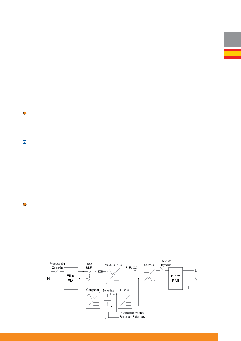
Chloride Active
para mantenerla protegida.
Cuando el equipo funciona en modo ECO, el cargador interno de baterías está trabajando. Por ello, las
baterías se mantienen cargadas.
Para detalles acerca de cómo habilitar/deshabilitar este modo de operación, véase 4.4.5.
4.1.6 Otros detalles de funcionamiento
Esta sección cubre otras funcionalidades proporcionadas por el equipo. Para detalles operativos, por favor
consulte los capítulos 4.2, 4.3 y 4.4
a) Función “Green Power”: cuando el equipo está en modo baterías y no hay carga en la salida, el equipo
se apaga automáticamente después de cinco minutos para ahorrar energía.
b) Arranque desde baterías: cuando esta funcionalidad está habilitada, el equipo es capaz de iniciar su
funcionamiento cuando la red no está presente, y de esta forma alimentar la carga directamente desde las
baterías.
ATENCIÓN: Cuando el SAI se pone en funcionamiento por primera vez, la red de entrada debe estar
presente.
c) Auto-rearranque: cuando esta funcionalidad está habilitada, el equipo arranca de forma automática ante
retorno de red después de la fi nalización del tiempo de autonomía. En caso contrario, es necesario poner
en funcionamiento el equipo manualmente.
NOTA: suponiendo que esta funcionalidad está activada, si hay un fallo de red justo después de de que el
equipo haya arrancado automáticamente, la autonomía será más corta ya que las baterías no se habrán
podido cargar completamente.
d) Fallo de cableado externo (site wiring fault): el equipo puede detectar si se han invertido los cables de
entrada de fase y neutro y reportar una alarma en ese caso.
e) Test de baterías: el SAI puede realizar un test de baterías de dos formas diferentes: manualmente, a
petición del usuario; o automáticamente, con un intervalo fi jo entre tests.
f) Salidas controlables: este SAI incluye dos grupos de salidas controlables (salida 1 y salida 2). Cada
grupo puede confi gurarse para que cada grupo de salidas se apague de forma automática cuando la
capacidad restante de las baterías descienda por debajo de un valor determinado (75%, 50%, 25% o 0%)
o cuando el usuario requiera.
ATENCIÓN: Se recomienda conectar las cargas más prioritarias a las salidas no controlables y las cargas
menos prioritarias a las salidas controlables.
g) Apagado/Encendido remoto (ROO) / Apagado remoto (RPO): el equipo dispone de terminales en la
parte posterior que permiten al usuario apagar y encender el equipo remotamente (ROO) o bien apagarlo
remotamente sin la opción de reiniciarlo remotamente (RPO). Para más detalles, por favor consulte la
sección 4.4.8.
h) Compatibilidad con grupos electrógenos (gensets): este SAI puede funcionar con la mayoría de los
grupos generadores disponibles en el mercado.
4.1.7 Diagrama de bloques
E
93
Page 96
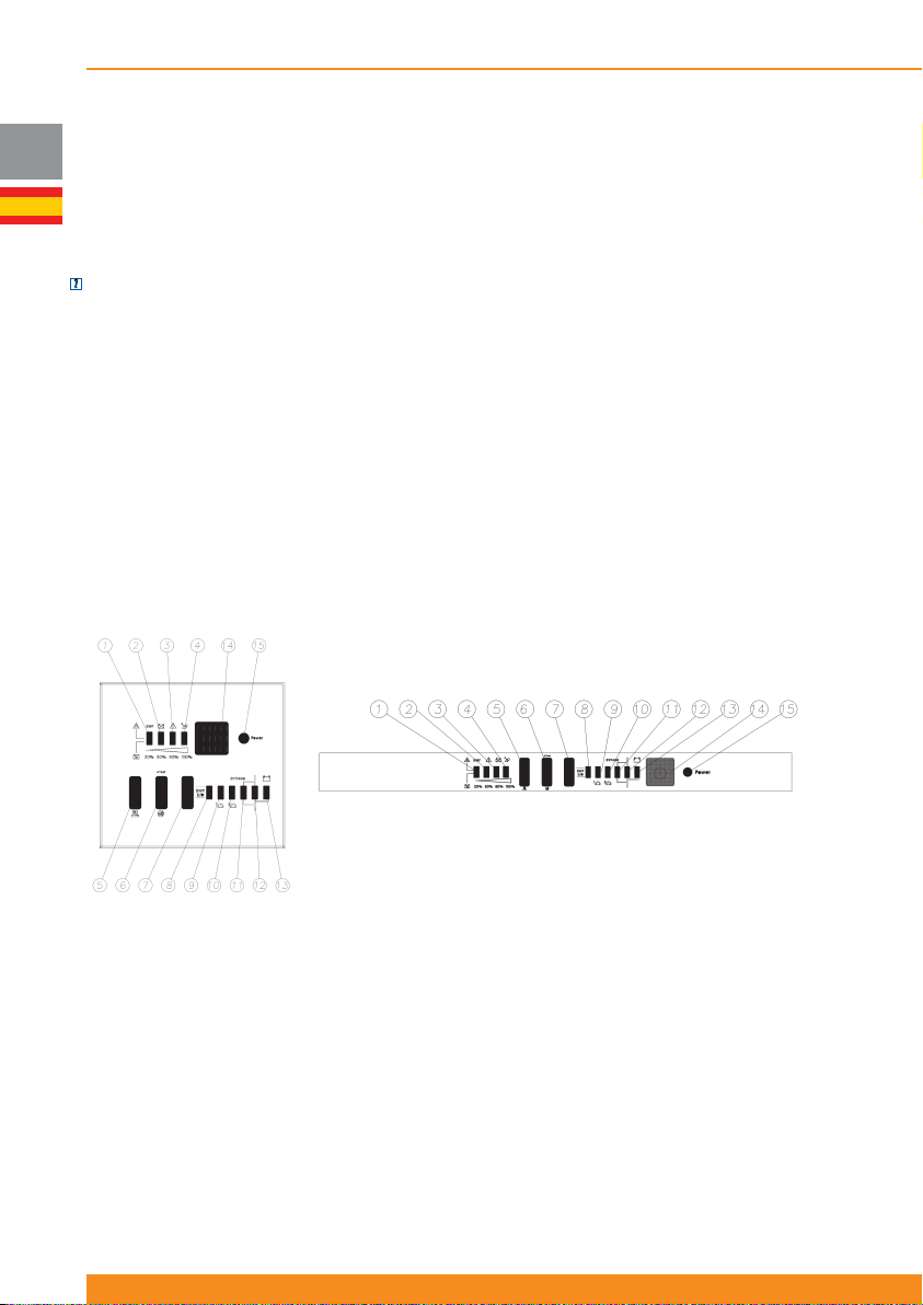
Chloride Active
4.2 Indicadores del Panel Frontal y Descripción de sus Elementos
E
4.2.1 Equipos con indicadores LED
Dependiendo de cada mercado local, los equipos pueden estar equipados con un panel frontal que
contiene una serie de botones e indicadores LED que informan al usuario del estado del SAI y permiten
cambiar su modo de operación.
NOTA: para los equipos con panel frontal con indicadores LED, hay paneles frontales con Display LCD
disponibles como accesorio y han de ser pedidos por separado. Para más detalles acerca de los mismos,
véase 4.2.2.
4.2.1.1 Descripción de los elementos
El panel frontal contiene una serie de botones e indicadores LED que informan al usuario del estado del
SAI y permiten cambiar su modo de operación:
- Botón y LED de Inversor ON/OFF
- Un diagrama de bloques simplifi cado muestra el modo de operación actual del SAI (modo línea, modo
baterías, modo bypass)
- Dos indicadores LED muestran el estado (ON / OFF) de los grupos 1 y 2 de salidas controlables
- Cuatro indicadores LED informan de fallos, porcentaje de carga de salida del SAI o porcentaje de nivel de
carga de baterías, dependiendo del estado del botón asociado
- Botón y LED de detección de fallo de cableado externo (site wiring fault)
1. LED de Detección de Fallo de Cableado Externo
2. LED de Fallo de Baterías
3. LED de Fallo de SAI
4. LED de Sobrecarga en el SAI
5. Botón de selección de información
6. Botón de Test de LED/Reset de Alarma
7. Botón de Activación/Desactivación de Detección de Fallo de
Cableado
8. LED de Activación/Desactivación de Detección de Fallo de
Cableado
94
945044.066
9. LED de ON/OFF de Grupo 1
10. LED de ON/OFF de Grupo 2
11. LED de Modo Bypass
12. LED de Modo Línea
13. LED de Modo Baterías
14. Botón de Inversor ON/OFF
15. LED de Inversor ON
Page 97
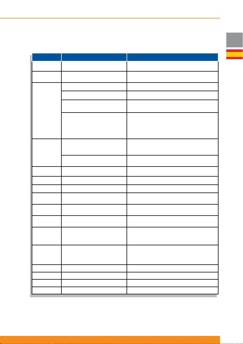
4.2.1.2 Operación
La siguiente tabla muestra las funciones de estos botones y LEDs.
Botón/LED Función Operación/Defi nición
Botón14
Botón 7
Botón 6
Botón de Inversor ON/OFF
Botón de Activación/Desactivación de
Detección de Fallo de Cableado
Silenciado/Reseteo de Alarma Presione un segundo para silenciar la alarma
Test de LED
Paso a bypass o retorno desde
Reseteo de Alarma LCM (alarma de
fi n de vida estimada de las baterías)
bypass
Presione un segundo para apagar/encender el inversor
Presione siete segundos para activar/desactivar la
detección de fallo de cableado externo (site wiring fault)
Presione para hacer un test de LEDs (todo los LEDs
Presione los botones 6 y 5 durante cuatro segundos
para pasar el equipo a bypass o para hacerlo retornar
Presione los botones 6 y 5 durante tres segundos
para resetear esta alarma (si la alarma está activa,
es necesario presionar los botones cuatro segundos
más para pasar el equipo a bypass, según lo explicado
parpadean)
desde bypass
más arriba)
Chloride Active
E
Botón 5
LED 1 (*)
LED 2 (*) LED de fallo de baterías Indica si se ha detectado un fallo de baterías
LED 3 (*) LED de fallo de SAI Indica si se ha detectado un fallo en el SAI
LED 4 (*) LED de sobrecarga en el SAI
LED 1, 2, 3 &
4 (*)
LED 8
LED 9
LED 10
LED 11 LED de Modo Bypass Indica si el equipo está en modo bypass (parpadea)
LED 12 LED de Modo Línea Indica si el equipo está en modo línea (ON)
LED 13 LED de Modo Baterías Indica si el equipo está en modo baterías (ON)
LED 15 LED de Inversor ON Indica si el inversor está encendido o apagado
(*) Estos indicadores LED muestran el nivel de carga de las baterías o el nivel de carga en la salida (dependiendo del botón
5) y normalmente deben ser interpretados conjuntamente. Sin embargo, en caso de ciertos eventos (fallo de cableado
externo, fallo de baterías, fallo de SAI o sobrecarga en el SAI), pasan a indicar dicho evento (parpadeando) y deben ser
interpretados individualmente.
Nivel de carga de salida
Activación/desactivación de arranque
desde baterías
LED de detección de fallo de cableado
externo (site wiring fault)
Nivel de carga de baterías / Nivel de
carga de salida
LED de Activación/Desactivación de
Detección de Fallo de Cableado
LED de ON/OFF de Grupo 1 de
salidas controlables
LED de ON/OFF de Grupo 2 de
salidas controlables
Presione para mostrar el nivel de carga de salida en
los LEDs 1, 2, 3 y 4 (por defecto, muestran el nivel de
Presione cinco segundos para activar/desactivar el
Indica si se ha detectado fallo de cableado externo
IIndica si se ha detectado sobrecarga en la salida del
Indican el nivel de carga de las baterías (por defecto), o
el nivel de carga en la salida si se presiona el botón 5
IIndica si la detección de fallo de cableado externo está
activada o desactivada (ON: activada, OFF:desactivada)
Indica si el grupo 1 de salidas controlables está
encendido o apagado (ON: encendido, OFF: apagado,
parpadeando: cambio de estado en ejecución
Indica si el grupo 2 de salidas controlables está
encendido o apagado (ON: encendido, OFF: apagado,
parpadeando: cambio de estado en ejecución)
carga de baterías)
arranque desde baterías
SAI
95
Page 98
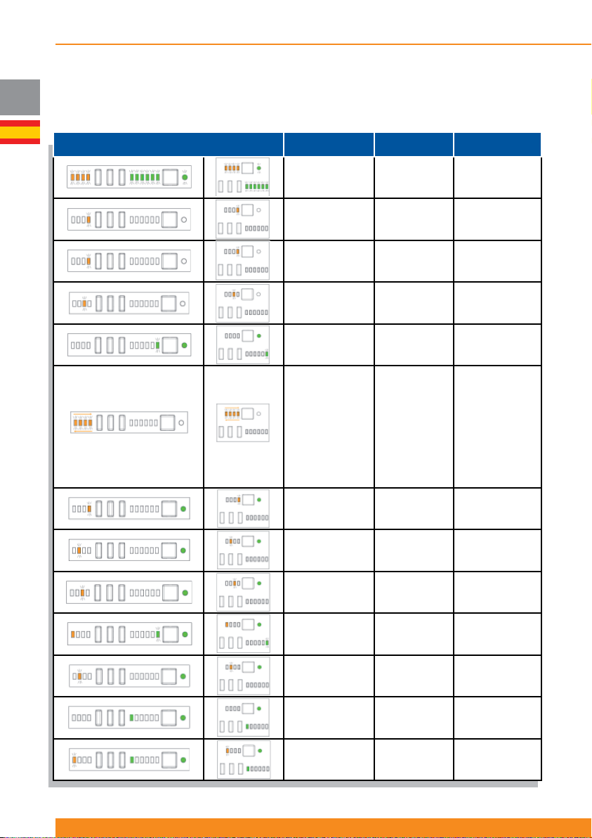
Chloride Active
4.2.1.3 Indicadores
E
La siguiente tabla muestra las indicaciones visuales y acústicas cuando ocurren ciertas condiciones. En
las indicaciones visuales solo se muestra el estado de los LEDs representativos en cada caso (los otros
pueden estar encendidos o apagados, dependiendo de otras condiciones de operación).
Estado de los LED Indicadores
Todos los LEDs
parpadean tres
veces
LED 4
parpadeando.
LEDs 1, 2 & 3
apagados
LED 4
parpadeando.
LEDs 1, 2 & 3
apagados
LED 3
parpadeando.
LEDs 1, 2 & 4
apagados
LED 13 parpadea
tres veces
LED 4 ON
LED 3 ON
LED 2 ON
LED 1 ON
LED 1 OFF
LED 2 OFF
LED 3 OFF
LED 4 OFF
LED 4 ON
Alarma
acústica
Tres pitidos
Pitido continuo
Pitido continuo
Depende del
fallo
Tres pitidos
Pitido continuo
Estado del SAI
Secuencia de
encendido del
SAI
Fallo por
sobrecarga
Fallo de
cortocircuito en
inversor
Otro fallo de SAI
Paso de modo
línea a modo
baterías
Advertencia de
apagado por
RPO
96
945044.066
LED 4
parpadeando.
LEDs 1, 2 & 3
apagados
LED 2
parpadeando.
LEDs 1, 3 & 4
apagados
LED 3
parpadeando.
LEDs 1, 2 & 4
apagados
LED 1 encendido,
LED 13
parpadeando
LED 2
parpadeando.
LEDs 1, 3 & 4
apagados
LED 8 encendido -
LED 1
parpadeando, LEDs
2, 3 & 4 apagados.
LED 8 encendido
Un pitido por
segundo
Un pitido por
segundo
Un pitido por
segundo
Un pitido cada
tres segundos
Un pitido cada
30 minutos
Pitido continuo
Advertencia de
sobrecarga
Baterías
desconectadas
o fallo en test de
baterías
Fallo de cargador
Batería baja
Alarma LCM (fi n
de vida estimada
de baterías)
Detección de
fallo de cableado
externo activada
Fallo de
cableado externo
detectado
Page 99
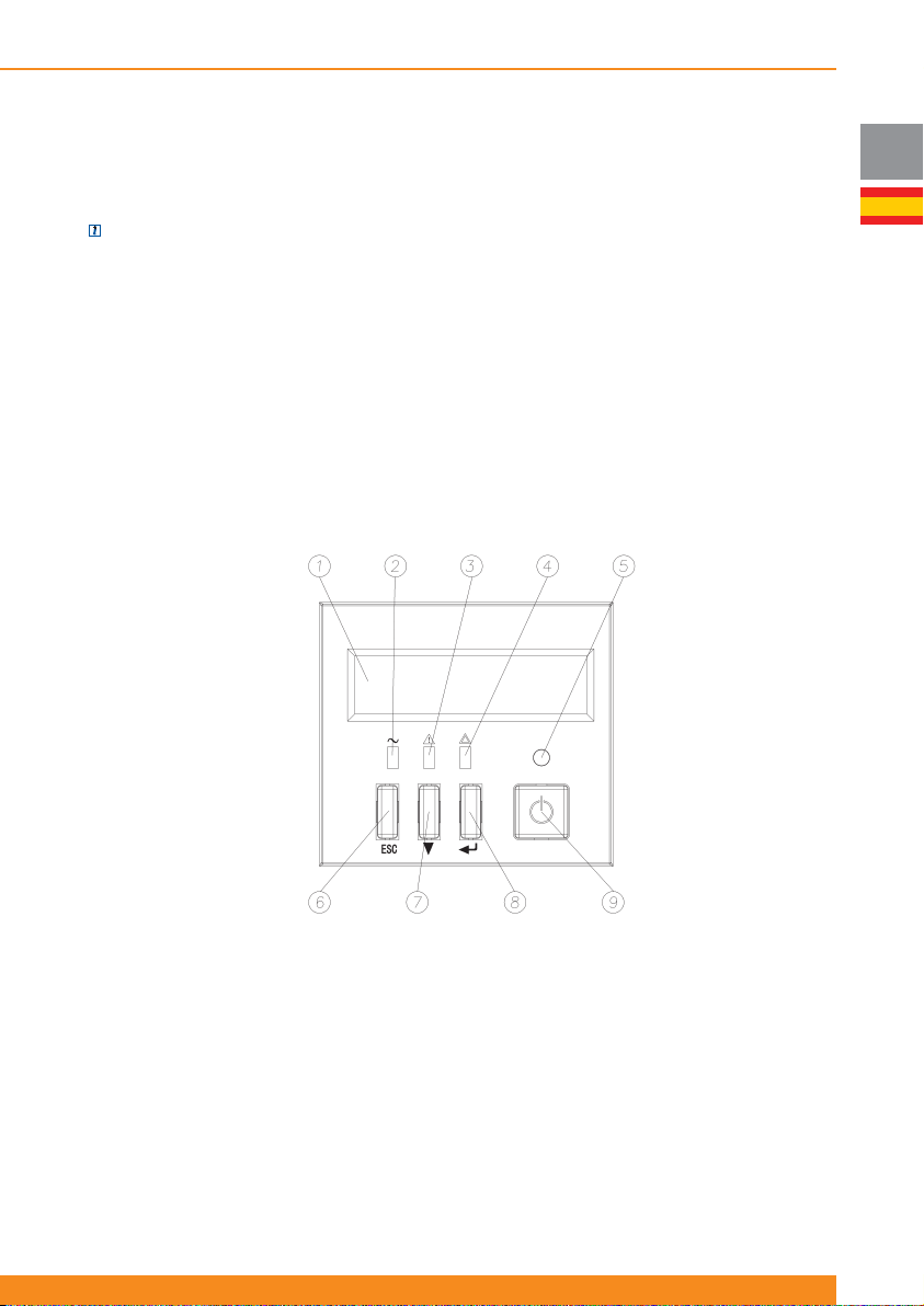
Chloride Active
4.2.2 Equipos con Display LCD
Dependiendo de cada mercado local, el SAI puede estar equipado con un panel frontal con Display LCD
en lugar de indicadores LED.
NOTA: para los equipos con panel frontal con indicadores LED, hay paneles frontales con Display LCD
disponibles como accesorio y han de ser pedidos por separado.
1. Display
2. LED de Red (verde): se enciende si la red de entrada está dentro de tolerancias
3. LED de Modo Bypass/Modo ECO (naranja): se enciende si el equipo está en bypass (forzado, por modo
ECO…)
4. LED de fallo (rojo): se enciende si el equipo está reportando un fallo: fallo de baterías, fallo de inversor…
5. LED de Inversor ON (verde): se enciende si el inversor está encendido
6. Botón ESC (sube un nivel en la jerarquía de menús y submenús). Nota: presione este botón durante 3
segundos para reseteo de alarma LCM (alarma de fi n de vida estimada de las baterías)
7. Botón de Scroll-Down (desciende al siguiente menú o submenú)
8. Botón de ENTER (baja un nivel en la jerarquía de menús y submenús o selecciona la opción en
pantalla)
9. Botón de Inversor ON/OFF (Enciende/apaga el inversor)
E
97
Page 100
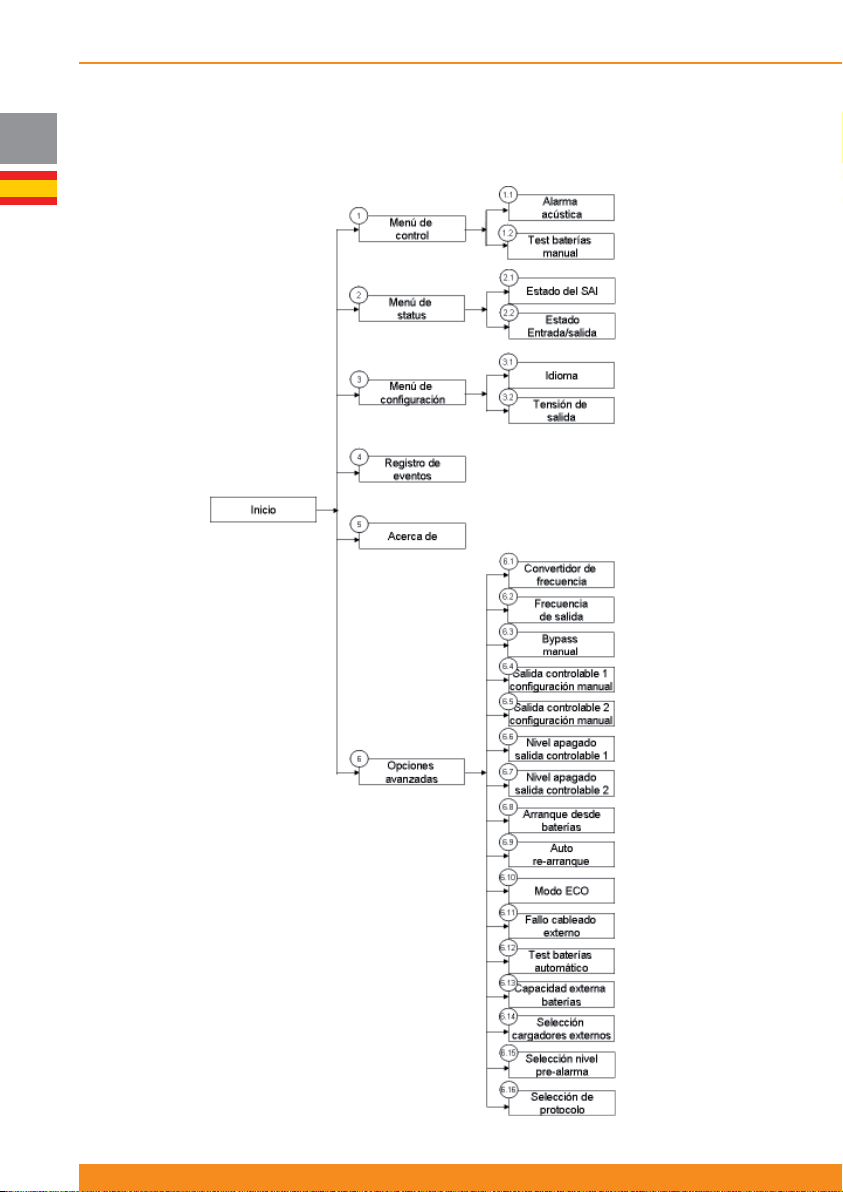
Chloride Active
4.2.2.1 Menús y funcionalidades
E
Las funciones disponibles en los menús y submenús se explican a continuación.
98
945044.066
 Loading...