

Page 1
IRIS Connect Series
Engineering Manual
Version 1.8
Page 2

Contents
1. Introduction ........................................................................................................................................................... 3
2. IRIS Communication Mechanism (Polling / Alarms) .............................................................................................. 4
3. Product Features ................................................................................................................................................... 5
4. Package Contents .................................................................................................................................................. 6
5. Board Configuration .............................................................................................................................................. 6
6. Before You Start .................................................................................................................................................... 7
7. Installing the IRIS Connect Dialler ......................................................................................................................... 8
Mounting ...................................................................................................................................................... 8
Power ............................................................................................................................................................ 8
Backup Batteries (optional) .......................................................................................................................... 8
Connections .................................................................................................................................................. 9
GPRS/3G SIM Card (IRIS Connect Duo only) ............................................................................................... 10
Dial Capture ................................................................................................................................................ 10
Pin Inputs .................................................................................................................................................... 10
Switch On and Test ..................................................................................................................................... 10
Configuration .............................................................................................................................................. 11
Panel Configuration .................................................................................................................................... 14
Testing ......................................................................................................................................................... 17
8. Main menu .......................................................................................................................................................... 17
GPRS/3G Network Scan .............................................................................................................................. 17
Installation Wizard ...................................................................................................................................... 18
Settings ....................................................................................................................................................... 23
Test ............................................................................................................................................................. 32
Trouble Report ............................................................................................................................................ 34
Battery Status ............................................................................................................................................. 35
About .......................................................................................................................................................... 35
9. Maintenance ........................................................................................................................................................ 36
Confirm Current Status ............................................................................................................................... 36
Checking Battery Status .............................................................................................................................. 36
Replacing Batteries ..................................................................................................................................... 36
Check Software Version / Reflash ............................................................................................................... 37
Communication Paths Checks .................................................................................................................... 37
Test Alarm Panel Alarms and Communication to ARC ............................................................................... 37
10. Specifications ....................................................................................................................................................... 38
Page 2 of 40 IRIS Connect Series Engineering Manual Version 1.8
Page 3

1. Introduction
The IRIS Connect range, consisting of the Solo and Duo models, offers a new concept in Alarm over IP (AoIP)
providing cost effective AoIP for the residential sector.
Both IRIS Connects are certified as suitable for all Grade 2 systems with an Alarm Transmission System (ATS)
configuration up to SP6 for single path (IRIS Connect Solo / Duo), or ATS configuration DP4 for dual path (IRIS
Connect Duo).
The IRIS Connect range is based on Chiron’s successful IRIS Connect range of AoIP diallers with the same hardware
and software used in all IRIS diallers; with the same level of security and features provided to military, governments,
banks and commercial industry but now also available to the residential sector.
The IRIS Connect Solo and Duo offers Wi-Fi as standard for configuration, polling and alerting, whereas the Duo also
offers a dual path system with GPRS/3G communications (4G and CDMA on request).
Using Chiron’s advances in hardware and software, the IRIS Connect is unique in providing battery backup for over
15 hours support in the case of main power source failure. This backup is provided with only 4 small NiMH AA
rechargeable batteries, which allow a longer replacement life and a smaller design.
Note 1: The 15 hours standby is based on 15 minute polling and recommended quality batteries. Performance may
be reduced with faster polling or other system loading.
Note 2: The IRIS Connect can be fitted without batteries and will run as a standalone device without battery
backup.
IRIS Connect Series Engineering Manual Version 1.8 Page 3 of 40
Page 4

2. IRIS Communication Mechanism (Polling / Alarms)
The polling / alarm mechanism used on the Chiron IRIS system is highly secure and flexible, and uses the IRIS Secure
Apps monitoring software (installed at the monitoring centres) with the IRIS Connect diallers.
It has been independently certified as compliant to the highest level of security available – Grade 4, ATS6 - within the
EN50131 standard for alarm systems.
The IRIS system is unique in its ability for the polling frequency to be varied which means that the polling profile can
be adjusted as necessary to take into account the grade of security required and the traffic bandwidth available.
Key features are:
Independently certified as compliant with EN50131-1 Grade 3 ATS configuration SP6 over Ethernet and ATS –
SP5 over GPRS for single path Ethernet and DP4 for dual path communications.
After initial installation all backup or alternative IP addresses for the Polling engines (main & backup) are
downloaded to the IRIS Connect dialler over the polling communications.
All polling and alarms are authenticated by the receiver (Polling Engine) using the secure and sophisticated
‘Challenge Handshake’ mechanism as used in military and credit card applications. Each remote IRIS dialler
proves its authenticity using a 256 bit security key. A new random number generated by the receiver (Polling
Engine) is used for every poll so it is not possible to substitute the dialler using playback or sequence prediction.
Unlike other systems each dialler can have a unique security key which can be changed at the monitoring centre
any time as required. For additional security the installer never needs to load the key or be aware of what it is.
Also unlike other systems, the polling frequency is not fixed and can be varied by the monitoring centre at any
time, from a period of 10 seconds for high security systems down to once a week for low security systems. This
means that polling rates can be optimised to deliver the grade of service required and minimise the bandwidth
required.
Polling and alarms are carried over the TCP/IP protocol that gives end-to-end error protection. This removes the
possibility with other protocols such as UDP that data packets are lost or re-sequenced in the network leading
to false alarms.
All polling and alarms are outbound from the dialler location to the monitoring centre and do not require the IP
address of the dialler to be known. No special set-up is required at the customer’s router, such as port mapping
for incoming calls. This feature is essential for operation with networks with dynamic addressing and standard
GPRS/3G networks.
Background communication path polling is also configurable at the monitoring centre and enables the IRIS
dialler to periodically poll over the backup communication path, and any faults with this communication will be
reported back to the IRIS Secure Apps system.
Each poll transaction is very small and with the authentication protocol is only about 500 bytes of data,
including all traffic in both directions. For fixed line IP networks there are no traffic costs.
Total traffic is proportional to the polling frequency. For example, at 10 second poll 180K bytes per hour and at 3
minutes polling this would reduce substantially to only 10K bytes per hour.
Even with tariffed networks such as GPRS/3G, and when running at a polling rate suitable for the highest level of
security, a typical cost is only a few Euros per month. For GPRS/3G in many cases the level of traffic falls within the
free bandwidth that comes with the SIM card contract and will effectively be at no cost.
Page 4 of 40 IRIS Connect Series Engineering Manual Version 1.8
Page 5

3. Product Features
Features
IRIS Connect
Solo
Duo
Fire retardant enclosure
NiMH battery backup
>15 hrs
>15 hrs
Wi-Fi
GPRS/3G
-
Dial capture
Relays
2
2
Inputs (Pins) 2 2
Serial RS485
Selectable
Selectable
Serial TTL
RS232 (BASIC)
Text messaging
-
Multi language menus
VoIP & SIP services
Option available on request
4G / CDMA
IRIS Connect Series Engineering Manual Version 1.8 Page 5 of 40
Page 6
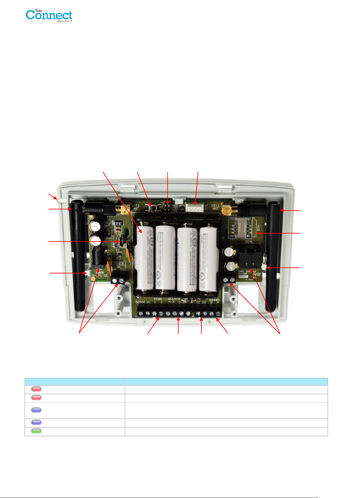
LED Colour
Indication
Red Flashing
Default state not currently configured
Red Constant
Wi-Fi successfully connected but still outstanding faults
Blue Flashing
In Access point mode (AP) for configuration but with no current
connection
Blue Constant
In Access point mode for configuration and a device is connected (AP)
Green Constant
Communicating and no current faults (flickers on every poll)
DC power
Pin inputs Relays RS232
RS485
Dial capture port
RJ45/RJ11 and
screw terminals
SIM card
holder
GPRS/3G
antenna
Serial
(TTL)
Battery case
Wi-Fi
antenna
Serial
selection
header
SYS LED
AP
button
Release
clip
Release
clip
Micro
USB
4. Package Contents
Contents dependent on model type:
Dialler board in plastic housing
3 x screws and plugs for fixing the housing to a flat surface
2 x screws and washers for fixing PCB to plastics
RJ11 cable
18k Ohms sense resistor
Already fitted on dialler board
GPRS /3G antenna (IRIS Connect Duo)
Wi-Fi antenna
5. Board Configuration
IRIS Connect
SYS LED
Page 6 of 40 IRIS Connect Series Engineering Manual Version 1.8
Page 7

6. Before You Start
Dialler account number
Monitoring centre IP address
Network name (SSID)
Security type (WEP/WPA/WPA2)
Password
Access Point Name (APN)
User Name (USR)
Password (PWD)
SIM Pin
Monitoring Centre (ARC)
Make sure that the monitoring centre to which the IRIS Connect device will send alarm signals is equipped with the
appropriate IRIS Secure Apps receiving system. The following information should be obtained from the monitoring
centre.
Wi-Fi Connection Details
The customer’s Wi-Fi network details are required in order to connect the IRIS Connect and your configuration
device (e.g. Smart Phone). The following information should be obtained from the customer.
GPRS/3G SIM Card and Access Point Name
If the installation uses GPRS/3G then a SIM card will be required. The IRIS Connect will also need to be given a
GPRS/3G ‘Access Point Name’ (APN) and other possible configurations as shown below. These can be obtained from
the SIM card provider.
IRIS Connect Series Engineering Manual Version 1.8 Page 7 of 40
Page 8
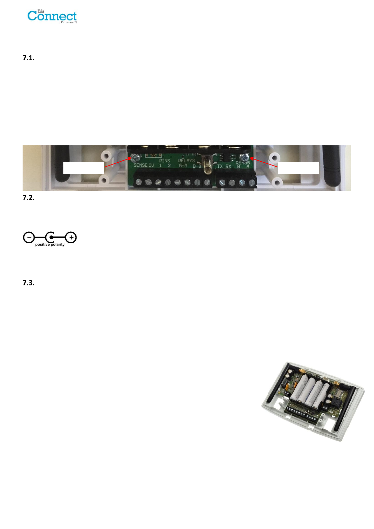
Fixing Screw
Fixing Screw
7. Installing the IRIS Connect Dialler
Use the following procedure to install your IRIS Connect dialler:
Mounting
Choose a suitable location, taking into consideration the routing of both power and dialler interface cables. To
remove the cover push the two release prongs on the underside of the plastic case as indicated on the back of the
case.
Once released, lift the lid slightly and push up until lid comes off, remove the dialler PCB (retained by two clips to left
and right off the board). Position the housing on the wall and drill three holes. Feed the cables through the opening
at the base of the plate, or via the ‘knockouts’, and secure the plate to the wall with the three screws supplied.
Slide the PCB back into the top retainers and within the side pillar and then gently secure the dialler back into place
using the release clips.
Secure the bottom part of the PCB using the 2 screws and washers supplied as shown in the image below:
Power
The IRIS Connect dialler can be powered from a separate or Aux 9-17V DC power supply specified to deliver up to 1A
current and can either use DC jack (centre positive polarity as shown below) or screw terminals indicated in Section 5
“Board Configuration”.
Note: For Radio & Telecoms Terminal Equipment Directive compliance the power cable must be no longer than 3
meters in length.
Fit the power cable. DO NOT APPLY POWER TO THE DIALLER UNTIL INDICATED.
Backup Batteries (optional)
IRIS Connect series has a battery backup capability and is designed to continue reporting to the IRIS Secure Apps
System at the monitoring centre to maintain confidence of link status in the case of a failure of the main power
source. The design provides over 15 hours battery support with 15 minute polling across either Wi-Fi or GPRS/3G.
Should the polling period be shortened or other activities such as alarm alerting by the panel, then the 15 hours
standby may be shortened.
IRIS Connect Solo:
If required please fit the batteries at this point.
IRIS Connect Duo using GPRS/3G communications:
If batteries are required DO NOT FIT until indicated in Section 7.9 “Configuration”.
Batteries must be approved to IEC61951-2 (EN61951-2).
The IRIS Connect requires 4 x 1.5V NiMh AA size rechargeable batteries (not included).
Recommended manufacturers/types are:
GP ReCyko 210AAHCB
Annsman maxE 2100
Note: Other battery types – including non-rechargeable batteries – must not be used.
The required battery capacity is 2000mAH minimum and ideally they should feature low self-discharge.
Maximum time to recharge to 80% = 32 Hours.
Overvoltage protection is triggered at 6.5V DC, with a deep discharge protection of 4V DC.
Note: System standby life and battery life can be reduced if lower quality batteries are fitted, this is not
recommended.
Page 8 of 40 IRIS Connect Series Engineering Manual Version 1.8
Page 9
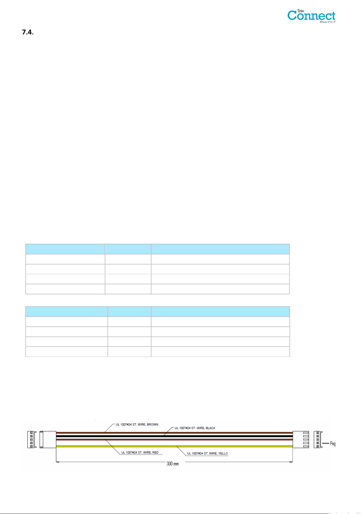
Connections
IRIS RS485 Screw terminal
To
Galaxy Data Bus Terminal
0V (Power)
Galaxy (-)
VIN (Power)
Galaxy (+)
A
Galaxy (A)
B
Galaxy (B)
IRIS RS485 screw terminals
To
Risco Bus1 terminal
0V (Power)
COM
VIN (Power)
AUX
A
YEL
B
GRN
Connect cables to the PCB for your system as shown on in Section 5 “Board Configuration”:
Wi-Fi: Wi-Fi (wireless) antenna already fitted to board.
GPRS/3G enabled systems (IRIS Connect Duo): GPRS/3G antenna already fitted to board.
Note: An external GPRS/3G antenna can be fitted if required.
Dial capture port (optional and for more information see section below).
2 x Pin inputs (optional and for more information see section below).
Optional Serial Connection
The following 3 connections are optional and depend on the panel connection method to be used. Use the ‘Serial
Selection Header’ and put the Jumper link on the option required.
RS485 currently available for Honeywell Galaxy data bus (Alarms and Upload/download) or Risco ProSys bus
(Upload/download) connections (optional).
Serial (TTL) currently available for Texecom Com1 connections (optional).
RS232 screw terminal (optional).
Note 1: For Radio & Telecoms Terminal Equipment Directive compliance any interconnecting cable (Dial capture,
Pin Inputs or Serial connection) must be no longer than 3 meters in length.
RS485 Connections (Honeywell Galaxy and Risco ProSys)
You can use the screw terminal blocks or the 4 Pin Headers (Molex).
If using the screw terminals the connections are:
IRIS Connect to Honeywell Galaxy panels
IRIS Connect to Risco ProSys panels
TTL Connections (Texecom Premier Range)
Can be ordered from Chiron
Description = Texecom RS232 Lead
Part No = Tex600
IRIS Connect Series Engineering Manual Version 1.8 Page 9 of 40
Page 10
Reference
ground pins
Pin inputs
1
2
4K7 Resistor
15K Resistor
1
2
Reference
ground pins
Pin inputs
GPRS/3G SIM Card (IRIS Connect Duo only)
DO NOT FIT SIM card until after you have performed the GPRS/3G Network Scan detailed in the Section 7.9
“Configuration” you will be prompted when to insert the SIM card.
Dial Capture
Dial capture enabled systems: Connect either the dial port RJ45 or the 2 dial screw terminals with the supplied RJ11
dialler cable to the alarm panel dialler telecoms line connection. If the alarm panel has screw connections, cut the
connector off the cable and strip the cable using the 2 inner wires.
Note: Polarity is not important in this instance.
Fit the supplied 18K sense resistor in parallel with the dialler output of the alarm panel, at the alarm panel end of the
cable.
Note: This resistor enables the dialler to detect cable faults and/or tampers and must be fitted at the alarm panel
end of the cable to function correctly, the monitoring centre will also need to enable the dial port monitoring from
the IRIS Secure Apps software to receive alarm notifications.
Pin Inputs
The IRIS Connect dialler has 2 Pin inputs that can be used to generate alarm messages. These can be:
Text messages via SMS (GPRS/3G).
SIA, Contact ID or Fast Format alarm messages over IP to the monitoring centre.
Note: These pin alarm inputs can also be used when the dialler is directly connected to an alarm panel via the dial
capture, serial or RS485 connections.
Via Open/Close Contact Source
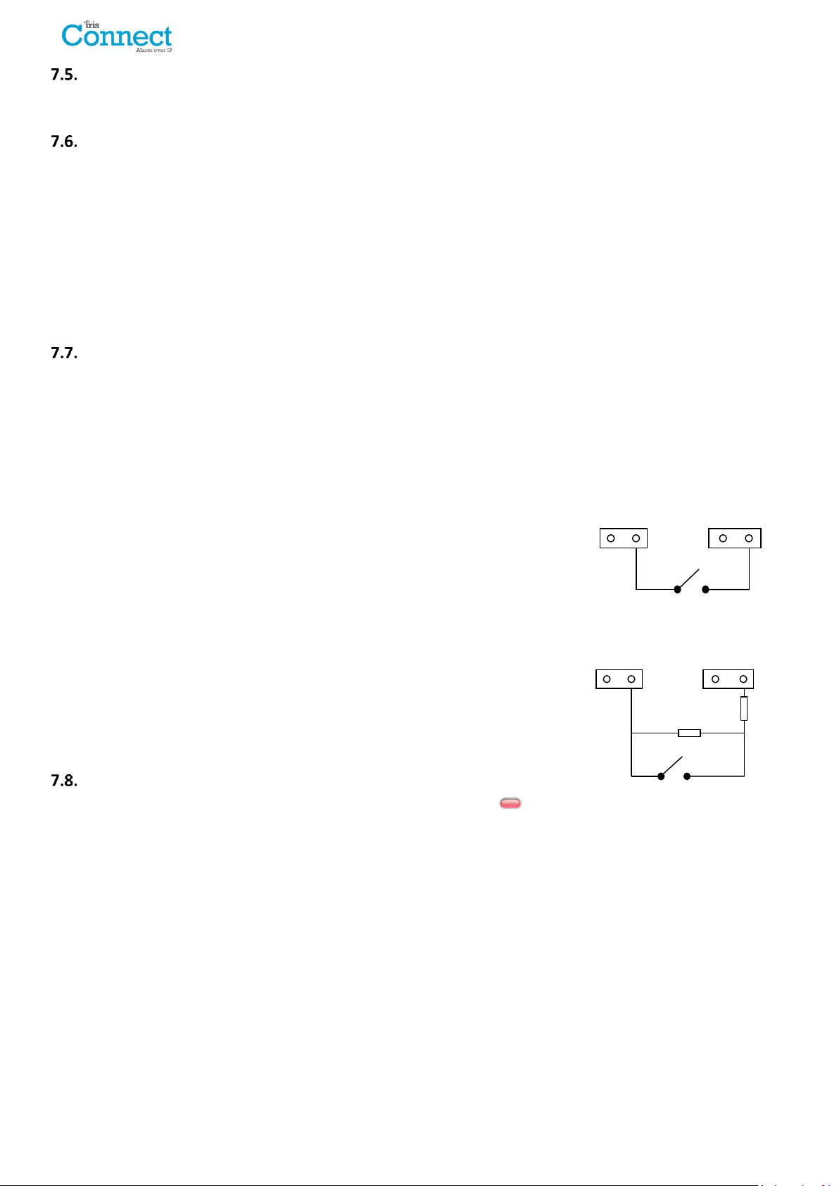
Each pin input is designed to be connected in a loop via an open/close contact
source from an alarm panel, or other device, to a reference ground pin available
on the IRIS dialler, as shown opposite.
Opening the contact (i.e. loop is open circuit) generates an alarm signal. Closing
the contact generates the equivalent restore signal.
Via Sense Resistors
It is also possible to link the contacts to the IRIS dialler via sense resistors so that
an open or short circuit tamper on the loop can be detected and the monitoring
centre alerted. In this case, the connections should be made as shown opposite.
Note: For this feature to work correctly it is essential that the resistors are
connected at the contact end of the loop and not the dialler end. The
monitoring centre must also enable the monitoring of this facility on the
dialler within the IRIS Secure Apps receiving system.
Switch On and Test
To confirm power is applied, look for the indicator SYS LED flashing red on the IRIS Connect dialler board, top left
hand corner.
Page 10 of 40 IRIS Connect Series Engineering Manual Version 1.8
Page 11

Configuration
To configure your dialler, use any of the following methods:
Web browser via Wi-Fi.
Alarm panel integration e.g. Honeywell Galaxy (RS485 connection) Texecom Premier range (Serial TTL
connection). Please refer to Section 7.10 “Panel configuration”.
Note: For connections to Honeywell Galaxy or Texecom Premier on the serial integration ensure that the
alarm panel is configured first as this will transmit configuration to the IRIS Connect dialler.
For more details on the alarm panel integration download the full panel installation manual from
http://www.chironsc.com/downloads_security.html.
Connect the board’s Micro USB connector to a laptop / PC running the IRIS Toolbox software.
Download the IRIS Toolbox user guide from http://www.chironsc.com/downloads_security.html.
Defaulting
If at any point a complete default of the dialler is required, use the following procedure:
1. Completely power down the IRIS Connect by removing the power and one of the batteries (if fitted).
2. Now press and hold down the AP button.
3. Reconnect the batteries if needed and reapply power whilst still holding down the AP button for 10 seconds.
IRIS Connect Series Engineering Manual Version 1.8 Page 11 of 40
Page 12
Configuration via Web Browser using Wi-Fi Connection
IRIS Connect dialler can be configured by the Wi-Fi connection and supports the following network security
WEP/WPA/WPA2 using a standard Web browser from any smart phone / tablet or laptop device.
The IRIS Web browser interface currently supports the following operating systems. Please note below if any
additional software is required to be installed:
Microsoft Windows based operating system (PC or laptop device) will require the initial installation of the Apple
Bonjour service. This can be downloaded from the following link:
http://support.apple.com/kb/DL999
Android operating system and Microsoft Windows phones will require the IRIS Connect App.
Available for Windows Phone or Android from the App Store, simply search for 'IRIS Connect'.
Apple iOS
Apple iOS operation system will work using the Safari web interface and already has the Apple Bonjour service
installed.
To initiate the Wi-Fi connection ensure that the IRIS Connect has power and the Wi-Fi antenna is connected and then
press the button labelled AP on the IRIS Connect.
When the AP button is pressed the SYS LED will flash ‘blue’ to indicate AP mode has been activated and is awaiting a
connection. You now have a 30 minute time window to search and find the IRIS Connect using either a smart phone,
tablet or laptop’s Wi-Fi connect search function.
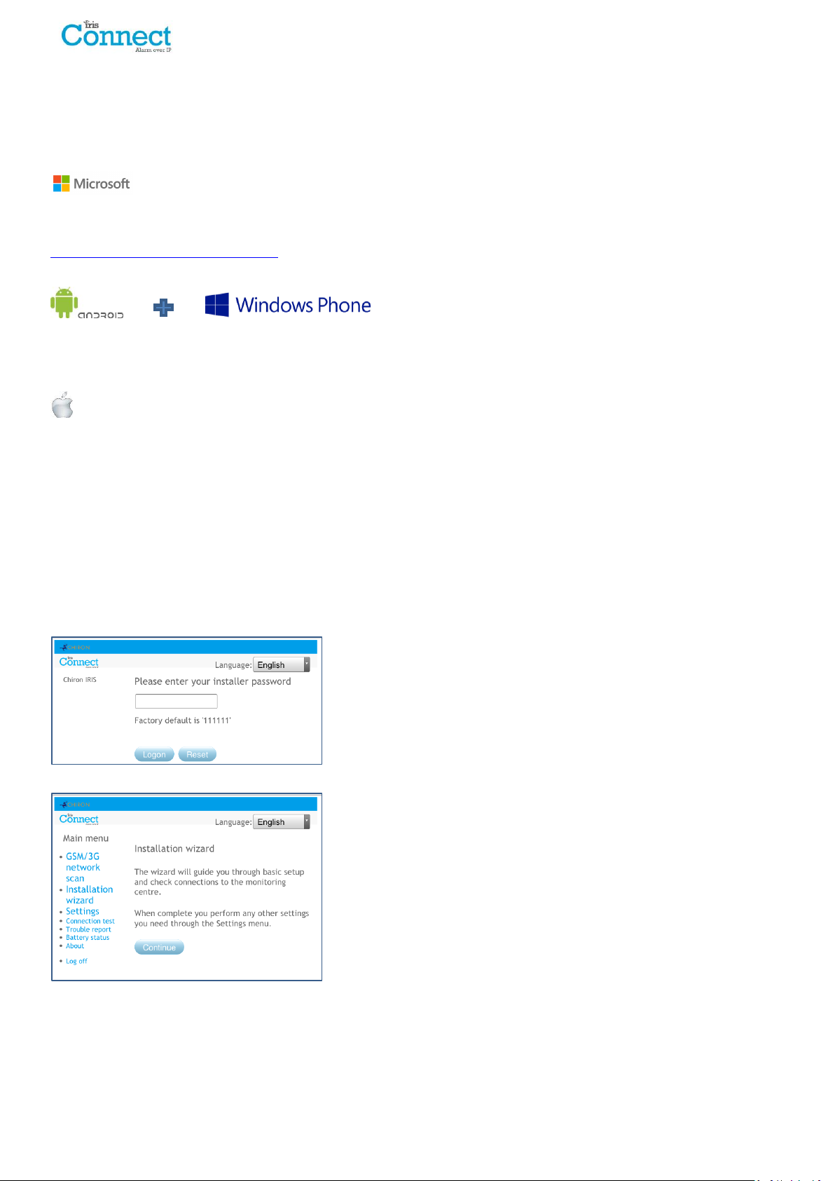
An ‘IRIS’ network should appear. Please connect to this which should turn the SYS LED solid ‘blue’ and using your
web browser connect to the IRIS Connect web interface by browsing to ‘iris.local’.
Enter the default installer code: 111111 and then click Logon.
You will be prompted to change the password, please record the new
password.
Enter and confirm a new password and press Submit.
Note: You are currently only communicating with the IRIS Connect and this is via its internal Wi-Fi Access Point.
The Main Menu is displayed.
Page 12 of 40 IRIS Connect Series Engineering Manual Version 1.8
Page 13
IRIS Connect Duo with GPRS/3G connection only:
GPRS/3G Network Scan
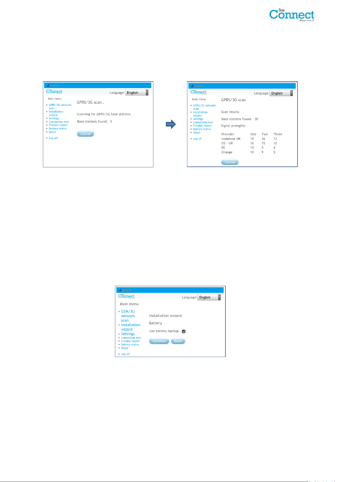
Select the ‘GPRS/3G network scan’.
The scan must be carried out without the SIM card fitted.
The dialler listens for every base station in range, requests operator name and records the signal strength. This will
take a few minutes to complete.
For a reliable GPRS/3G connection it is recommended that for the chosen network (SIM card) used there should be
at least two base stations with signal strength (CSQ) of 10 or more.
If the signal strength is below or close to minimum then try to reposition the IRIS Connect or use an external building
or high gain antenna (if necessary), and rerun the network scan to check signal strength.
Once you have the required GPRS/3G signal strength power down the dialler and insert the SIM card into the SIM
card holder, and insert the 4 x AA batteries if required then power the dialler back up.
Now press the button labelled AP again and on your connection device connect to the ‘IRIS’ network and using your
web browser connect to the IRIS Connect web interface again by browsing to ‘iris.local’.
Enter in the installer code setup beforehand and then select the Installation Wizard as indicated next.
IRIS Connect Solo or Duo without GPRS/3G or after network scan completed on Duo:
Installation Wizard
Select the Installation Wizard and follow the on screen prompts.
Note 1: If installing the IRIS Connect without batteries then please untick the ‘Use battery backup’ option.
Note 2: During the Installation Wizard the Wi-Fi status screen and the signal strength will be displayed. For a
reliable Wi-Fi connection it is recommended that the Wi-Fi network used should have a signal strength of 20 or
more. If this signal strength is lower than suggested try moving the IRIS Connect nearer the Wi-Fi router.
Once Installation Wizard is completed and any additional panel interface configuration setup via the settings menu,
check / configure the panel for the connection method being used and the current battery status.
To check the current battery statuses go to the option ‘Battery status’ in the main menu and this will indicate the
current status of the batteries.
IRIS Connect Series Engineering Manual Version 1.8 Page 13 of 40
Page 14
IRIS Connect
Alarm Panel
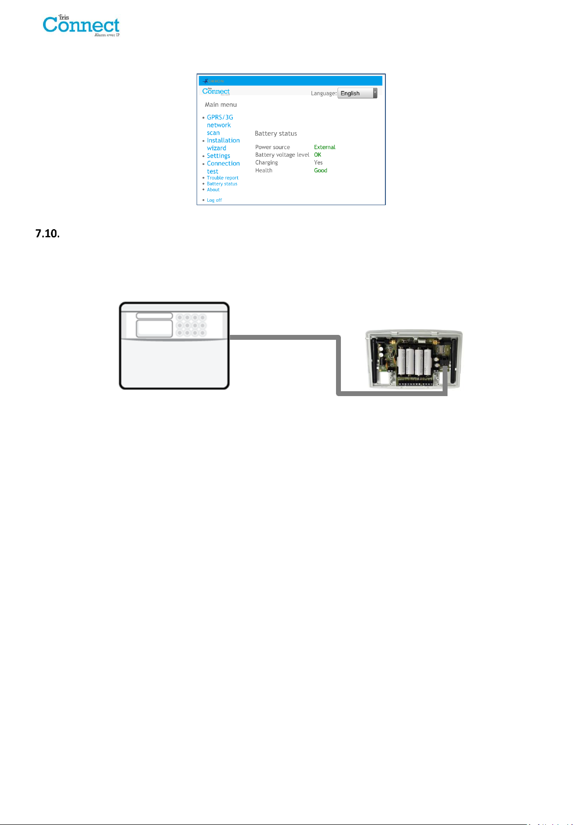
Please go into the Battery Status option and confirm that the Health Status is showing as “Good” before leaving site,
as shown below:
Panel Configuration
Panel configuration for dial capture
If connecting the IRIS Connect dialler via the dial capture method which is connecting the Telecoms module to the
dial port of the IRIS Connect, the following options will need to be configured:
Alarm Panel Configurations:
Dial Type = Tone dial.
Telephone Number = The 12 digit format of the monitoring centre IP address
e.g. 192.168.0.34 would become 192168000034.
Account Number = 4 – 6 digit account number allocated by the monitoring centre.
Alarm Format = Fast Format (DTMF), Contact ID, SIA (level 1 to 3), or Robofon alarm format.
Note: If the ‘Alarm Override’ mode is selected, the IRIS Connect dialler replaces the phone number and the
account number used by the alarm dialler with the IP address of the monitoring centre and account number
entered during configuration, so there is no need to change any settings on the alarm panel.
The alarm signals commissioning can now be performed and sign off required by the monitoring centre (ARC).
Page 14 of 40 IRIS Connect Series Engineering Manual Version 1.8
Page 15

Configuration from Honeywell Galaxy Panel via RS485
The IRIS Connect dialler can simulate a Galaxy Ethernet Module (Comm’s Mod 4) and remote keypad, for both
Alarms and Remote Service Suite upload/download connection.
Note: To use the SMS messaging function from the Galaxy panel it will be required to emulate the external PSTN
module, and setup the Galaxy External PSTN module settings see the IRIS Honeywell Galaxy Installation Manual.
For further information on both the Galaxy installation and Remote Service Suite upload/download connection
please refer to the IRIS Honeywell Galaxy Installation Manual or IRIS Remote Service App Client User Guide for
Honeywell Galaxy range available from http://www.chironsc.com/downloads_security.html.
Connect the IRIS Connect dialler to the Galaxy Data bus as indicated in Section 7.4 “Connection” ensuring that the
‘Serial Selection Header’ is selected for ‘485’, then power up the Galaxy control panel, if not already powered up.
The configuration menu on the Galaxy panel for the Ethernet card is found at location 56 (Communications) entry 4
(Ethernet), please enter the required information as indicated below.
You must enter Engineer Mode on the Galaxy to access these options.
56 = Communication
4 = Ethernet
01= Module Config 1 = IP Address - Leave blank
2 = Site Name - Leave blank
3 = Gateway IP - Leave blank
4 = Network Mask - Leave blank
Note: Leave all “Module Config” addresses blank as you are using a WiFi and not Ethernet connection
02 = Alarm Reporting 1 = Format - Set to SIA level 3
2 = Primary IP
1 = IP Address - Set this to the IP address of the monitoring centre
e.g. 80.176.196.135
Note: Secondary IP address not required as the backup IP address will be
download by the IRIS Secure Apps system to the dialler.
4 = Account No. - Enter in the account number allocated by the
monitoring centre.
03 = Remote Access 1 = Access Period - Set to 4 ‘Any Time’
2 = Mode - Set to ‘Direct Access’ if making calls into site from
Honeywell Remote Service Suite (RSS) for remote access
directly or via the IRIS Remote Service App client.
- Set to ‘MGR Authorise’ if making the remote access calls
out from site to the Honeywell RSS, and then set the ‘call
IP1’ IP address to the IP address for the Honeywell RSS
communication server e.g. 80.176.196.135
Note: The IRIS Connect does not support the Honeywell encryption as uses its own encryption so please
ensure the following 2 options are turned off.
9 = Encrypt 1 = Alarm Report - Set to Off
2 = Remote Access - Set to Off
After you have entered the relevant information exit Engineer Mode and the panel should now detect 2 new RS485
modules (Comms Mod 4 & Keypad 15).
If the new modules are not detected then it may be necessary to power off the Galaxy panel, check the dialler
connections, and power back on.
Now go back into Engineer Mode, select the menu option sequence 56.04.05 ‘ENGINEER TEST’ and send the test
alarm. Check to see if this test alarm has been received by the monitoring centre (ARC).
Note: If required to default the IRIS Connect and start again this can be done by setting the primary IP address
within the Galaxy menu 56.04.02.02 to an IP address of 127.0.0.1.
The alarm signals commissioning can now be performed and sign off required by the monitoring centre (ARC).
IRIS Connect Series Engineering Manual Version 1.8 Page 15 of 40
Page 16
Configuration from Texecom Premier panels via Serial TTL
The IRIS range has been fully integrated into the Texecom Premier Alarm panel range and most configurations can
be configured from the panel keypad.
Connect the IRIS Connect dialler via the TTL header to the Texecom Com 1 header as indicated in Section 7.4
“Connection” ensuring that the ‘Serial Selection Header’ is selected for ‘TTL’, then power up the Texecom panel, if
not already powered up.
Below is a detailed description of the configuration setting for the latest Texecom Premier Elite range. If you have
different version of the Texecom Premier range or want to perform upload/download connection via Wintex then
please refer to the IRIS Texecom Premier Installation manual or IRIS Remote Service App Client User Guide for
Texecom range from http://www.chironsc.com/downloads_security.html.
Please use the Texecom keypad or Wintex software to configure the following configuration within the Texecom
alarm panel, please refer to the Texecom Installation guide for further details:
Texecom Premier Elite Series (12, 24, 48, 88, 168, 640)
7 = UDL/DIGI Options
3 = Program Digi
Arc 1 Protocol - Set to the alarm format requested by the monitoring centre or customer
i.e. Fast Format, Contact ID, or SIA level 2/3.
Primary No - Set this to the IP address of the monitoring centre in a 12 digit format
i.e. 80.176.196.135 = 080176196135.
Secondary No - Leave blank as the IRIS System will receive the secondary number from
the monitoring centre IRIS Secure Apps system.
Account Number - Enter in the account number allocated from the monitoring centre.
Dialler Attempts - Leave as the default 3.
Report options - The reporting options will change depending on the alarm format
selected, please set up the various reporting option for the alarm event you
wish to send to the monitoring centre.
Config - Enable the Connect via IP (Key press 7).
4 = Digi Options - Enable the Digi (key press 1) should now see E on keypad option screen.
5 = UDL Options
4 = UDL Password - Must match the UDL password setup within Wintex.
6 = Ring Count - Set to 1 for use with the IRIS Remote Service App.
7 = Setup Modules
2 = Setup IP Data
1 = ComIP Address - Leave blank.
2 = ComIP Port - Program the Port number for Wintex connection normally 10001.
3 = ComIP Gateway - Leave blank.
4 = ComIP Netmask - Leave as default.
5 = Polling/SMG IP - Set this to the IP address of the monitoring centre in a 12 digit format
i.e. 80.176.196.135 = 080176196135.
3 = Setup GPRS Data
0 = Access Pnt Name - Enter the GPRS/3G access point name for the SIM card you are installing.
1 = User Name - Enter the user name for the SIM card if assigned.
2 = Password - Enter the password for the SIM card if assigned.
8 = Com Port Setup
2 = Com Port 1 - Set to IRIS IP Module.
The alarm signals commissioning can now be performed and sign off required by the monitoring centre (ARC).
Page 16 of 40 IRIS Connect Series Engineering Manual Version 1.8
Page 17
Testing
Once all configurations are complete perform a full commissioning test with the monitoring centre. This will
normally involve testing normal alarm transmissions over all communication paths from the alarm panel to the
monitoring centre, and verifying that these are successfully received.
8. Main menu
The IRIS Connect has a number of options under the main menu and
below we will go through each section explaining their functions and
uses.
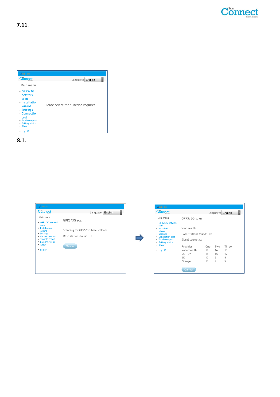
GPRS/3G Network Scan
IRIS Connect Duo with GPRS/3G connection:
The GPRS/3G network scan function allows overall feedback of signal strength from all providers in the area. This
should be performed on installation as detailed in Section 7 “Installing the IRIS Connect Dialler” and also after
installation, for example during maintenance, as location signal stregnth can change e.g. new building in the area or
cosmetic changes in the current location (storage racking etc).
The scan must be carried out without the SIM card fitted.
The dialler listens for every base station in range, requests operator name and records the signal strength.
This will take a few minutes to complete.
For a reliable GPRS/3G connection it is recommended that for the chosen network (SIM card) used there should be
at least two base stations with signal strength (CSQ) of 10 or more for reliability.
If the signal strength is below or close to minimum then try to reposition the IRIS Connect or use an external high
gain antenna (if necessary), and rerun the network scan.
Once the required GPRS/3G signal strength has been obtained power down the dialler and insert the SIM card into
the SIM card holder, then insert the 4 x AA batteries if required and power the dialler back up.
IRIS Connect Series Engineering Manual Version 1.8 Page 17 of 40
Page 18
Installation Wizard
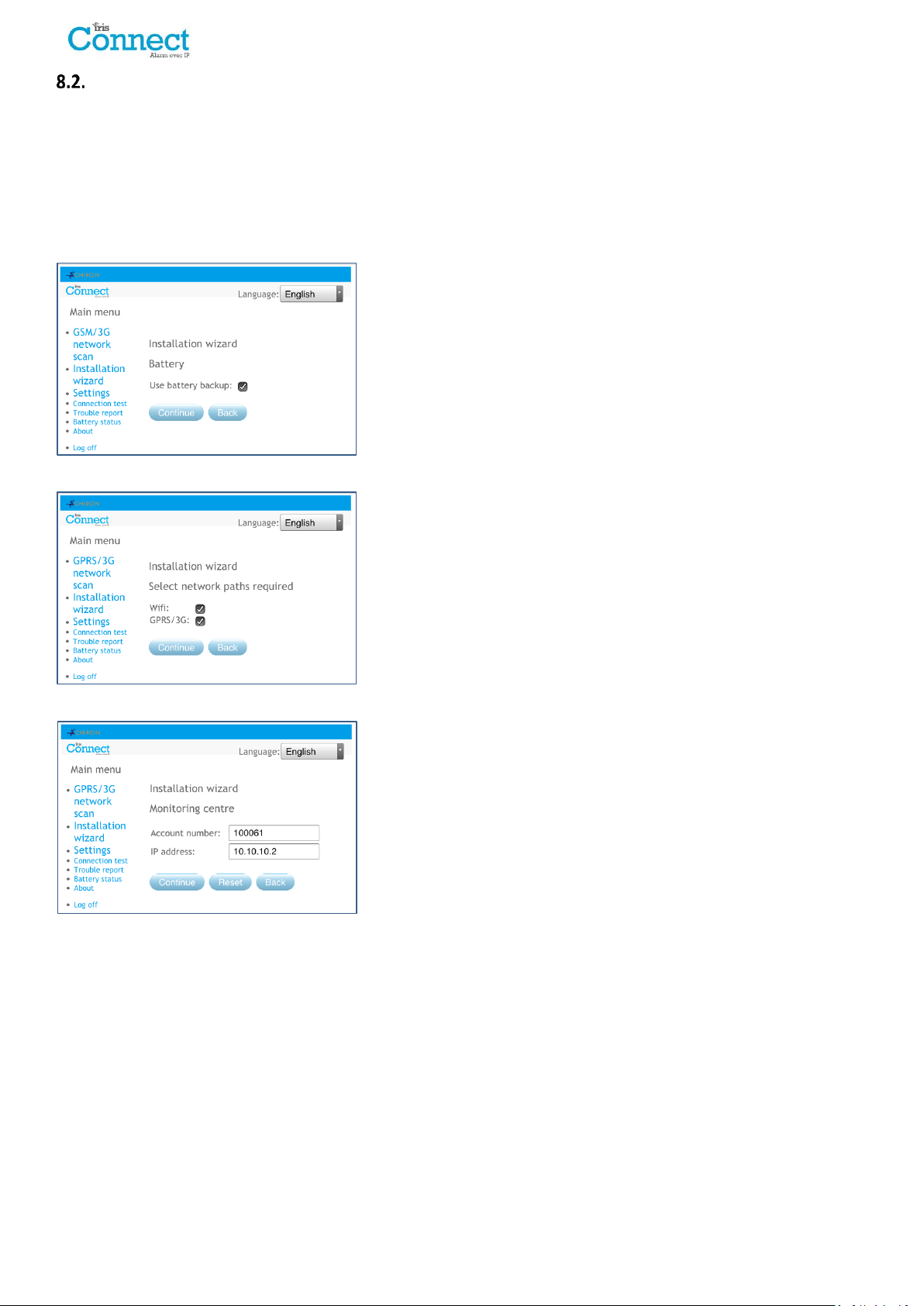
The Installation wizard guides you through the set up process for the IRIS Connect dialler and if there is a problem
you will be told what it is and will not be allowed to continue until it is solved.
Note: During the Installation Wizard process some configurations may already be setup, when using a panel
integrated with the serial or RS485 connection. These configurations would have been downloaded from the
alarm panel setup and if these are incorrect they need to be corrected first in the alarm panel.
Select the Installation Wizard and follow the on screen prompts.
Battery
The first option within the Installation wizard is to confirm battery
backup is being used.
Note: If you are installing the IRIS Connect dialler without batteries
then please untick the ‘Use battery backup’ option.
Use Battery backup
If installing the IRIS Connect dialler without batteries then please
untick the Use battery backup option.
Network paths
The IRIS Connect Solo dialler has Wi-Fi for Single path communication
whereas the IRIS Connect Duo has Wi-Fi and GPRS/3G options for
single or dual communications.
Select the paths required between Ethernet, GPRS/3G and then click
‘Continue’.
Monitoring centre
Now you are asked to enter the account (name / number) reference
allocated by the monitoring centre which can be alphanumerical and
up to 32 characters long, but normally you would expect a 4 or 6 digit
numerical account number.
You will also be asked to enter in the monitoring centre IP address. This
can be obtained from the monitoring centre and would normally be
the external IP address for their IRIS Secure Apps system.
Page 18 of 40 IRIS Connect Series Engineering Manual Version 1.8
Page 19
Wi-Fi
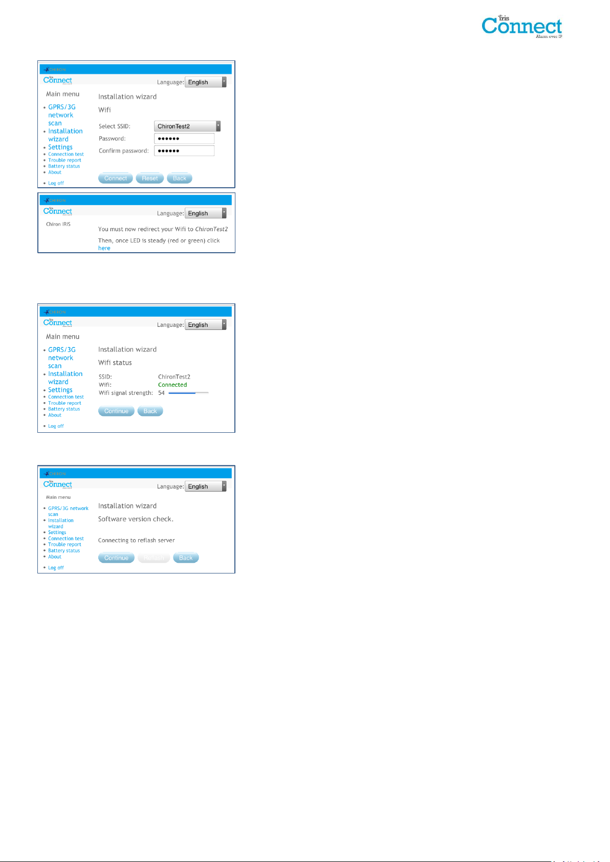
The IRIS Connect dialler will now show results of a Wi-Fi network scan
for all current networks available. The networks found will be shown in
the ‘Select SSID’ drop down box.
Now select or enter the valid Network name (SSID) and Password
(wireless key) for the Wi-Fi network you wish to connect to. Click
Connect.
You will now be prompted to connect your programming device to the
Wi-Fi network and once connected to this network then click the ‘here’
link to continue.
You will now be connecting to the dialler via the Wi-Fi network and be asked to re-enter the Installer password setup
earlier and click ‘Logon’.
Wi-Fi status
The dialler will now confirm to which Wi-Fi network it is connected and
its signal strength.
For a reliable Wi-Fi connection it is recommended that for the network
used there should be signal strength of 20 or more. If this signal
strength is lower than suggested try moving the IRIS Connect dialler
nearer the Wi-Fi router.
Checking Software is latest
The IRIS Connect dialler will now check with Chiron’s global reflash
server to see if a new version is available. If it is the option to ‘Reflash
now’ will be given.
The Reflasher option has a separate password to the Installation
password and if this is the default ‘111111’ you will be requested to
change this password as required for EN50136-2.
Note: If there is a newer version available we recommend reflashing
the IRIS Connect dialler to the latest version before completing the
installation.
IRIS Connect Series Engineering Manual Version 1.8 Page 19 of 40
Page 20
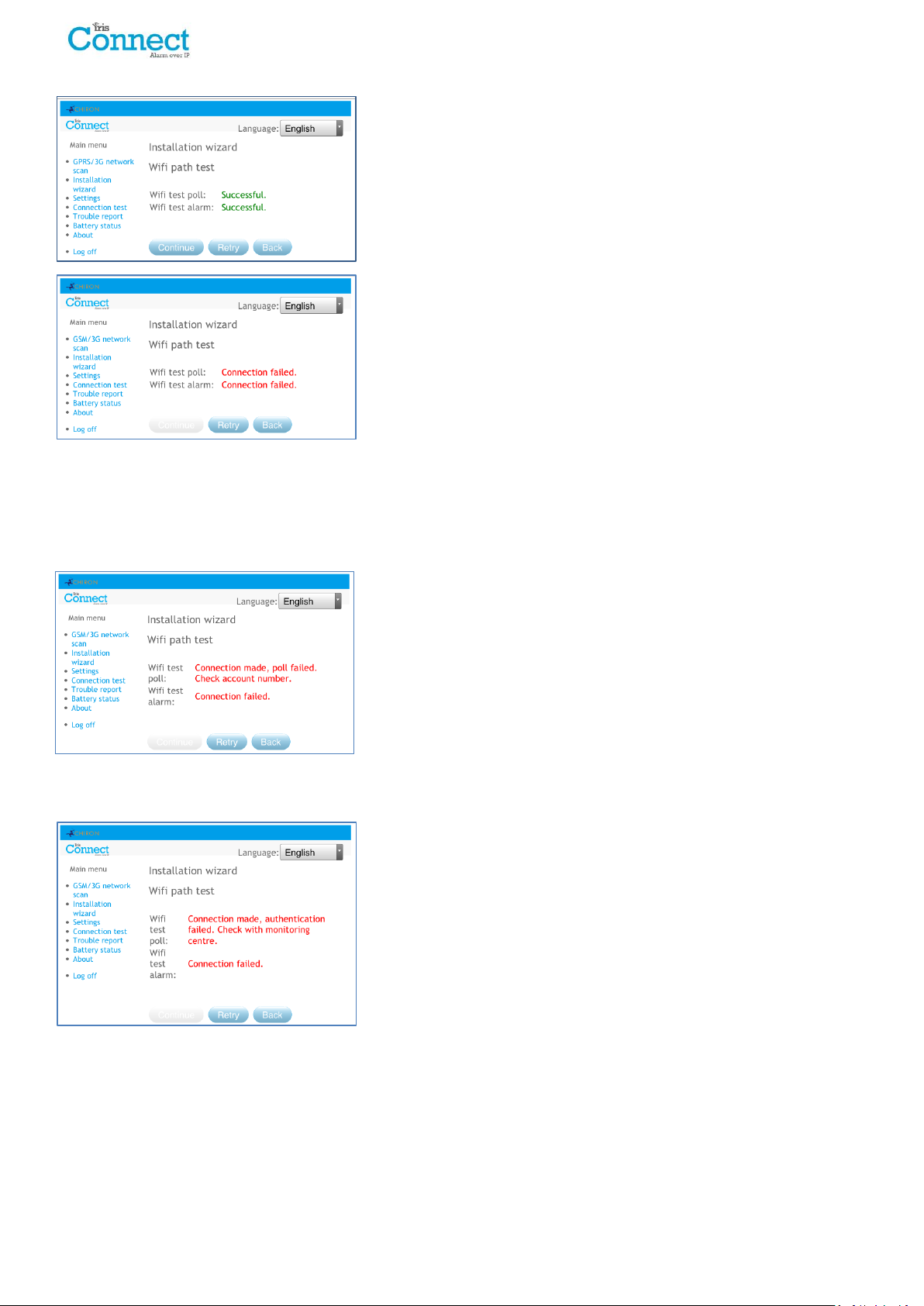
Wi-Fi check
Next the dialler will send a test poll and alarm message to the
monitoring centre to check the Wi-Fi connection.
Please ensure that both of these are successful and if not the dialler
will indicate the possible issues and the configuration to check as
shown below:
Note: The normal sequence of sending test alarms from the alarm
panel must still be carried out.
This indicates that the poll call did not reach the IRIS Secure Apps
system and could be caused by one of the following:
Check that the monitoring centre IP Address entered is correct.
Check the Wi-Fi setup for the IRIS Connect dialler, and confirm with the customer IT department that you have
connected to the correct network.
Ensure that the alarm and polling port is not being blocked outbound by the customer’s firewall. The required
ports are 53165 TCP.
This indicates that the test poll call has reached the IRIS Secure Apps
system but the account number is not valid.
Check that the account number is programmed correctly.
Check with the monitoring centre that the account in IRIS Secure Apps is setup.
This indicates that the test poll call has reached the IRIS Secure Apps
system but the security keys do not match.
The security key is a feature designed to prevent substitution attacks against both dialler and monitoring centre.
When enabled a randomly generated 32 byte key is transmitted to the dialler. This key must be used for all future
polling authentication. Both the dialler and the Polling Engine authenticate each other, thus ensuring that a
replacement dialler cannot be used to fool a Polling Engine into thinking its status is unaffected during malicious
tampering; it also ensures that the dialler will be aware if its IP traffic has been maliciously redirected to a different
IRIS Polling Engine.
If the installer has recently defaulted or replaced the IRIS Connect dialler then the IRIS Secure Apps operator will
need to re-load the security key into the IRIS Connect dialler using the Allocator App.
After checking each of the configuration options reattempt to test the connection.
Page 20 of 40 IRIS Connect Series Engineering Manual Version 1.8
Page 21
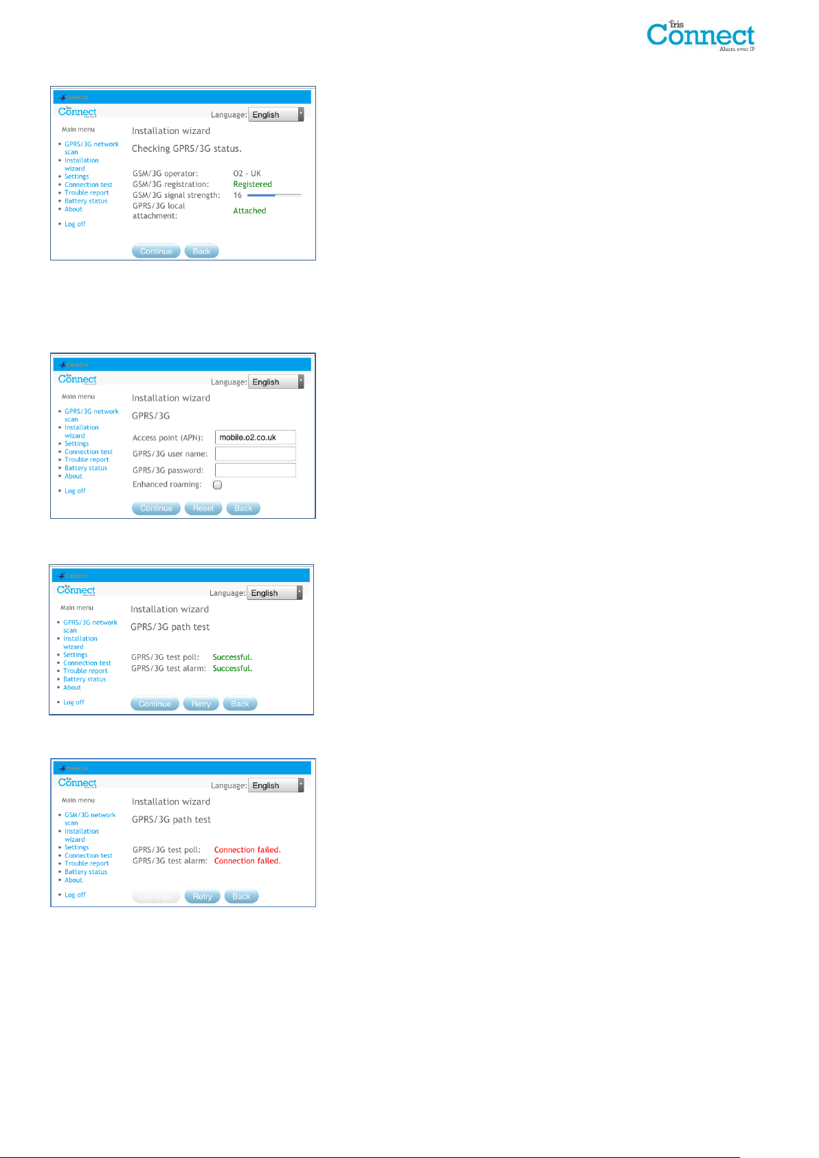
GPRS/3G (IRIS Connect Duo only)
If you selected connection via GPRS/3G, the dialler will display the
current operator / signal strength for the base station to which it is
currently attached.
Note: A signal strength of 10 CSQ or higher is required for a reliable
connection.
If the IRIS Connect dialler displays GSM/3G registration and GPRS/3G
attachment, then click ‘Continue’.
If this screen shows GSM/3G not registered then check the SIM card is inserted correctly and contact the SIM
provider to confirm it is enabled.
If the GPRS/3G attachment is not attached then check with the SIM provider that GPRS/3G is enabled.
All GPRS/3G networks require the Access Point Name (APN) to be set.
A few also require User Name (USR) and Password (PWD).
Enhanced Roaming
This option enables an enhanced roaming feature when used with a
Roaming SIM.
Standard Roaming SIMs will always attach to the preferred provider
even if this has the weakest signal.
Enabling this option forces the GPRS/3G attachment to attach to the
strongest signal base station. This allows the IRIS Connect dialler to be
even more resilient with the GPRS/3G network.
Now enter in the information from the SIM provider for this SIM card then Click ‘Continue’.
The IRIS Connect dialler will make a test poll and test alarm
transmission over the GPRS/3G network.
Note: The normal sequence of sending test alarms from the alarm
panel must still be carried out.
Please ensure that both of these are successful and if not the dialler will indicate the possible issues and the
configuration to check as shown below:
This indicates that the poll call did not reach the IRIS Secure Apps
system and could be caused by one of the following:
Check monitoring centre IP Address entered is correct.
Note: If using Wi-Fi on a VPN, for example, then the monitoring centre IP would be for this connection and
not the correct one for GPRS/3G. In this case please have the monitoring centre operator check the Allocator
setup for this account and try a Reload Parameters.
Check GPRS/3G settings are correct for APN, User name, Password and Pin.
Ensure SIM card is setup for GPRS/3G Machine to Machine data.
IRIS Connect Series Engineering Manual Version 1.8 Page 21 of 40
Page 22
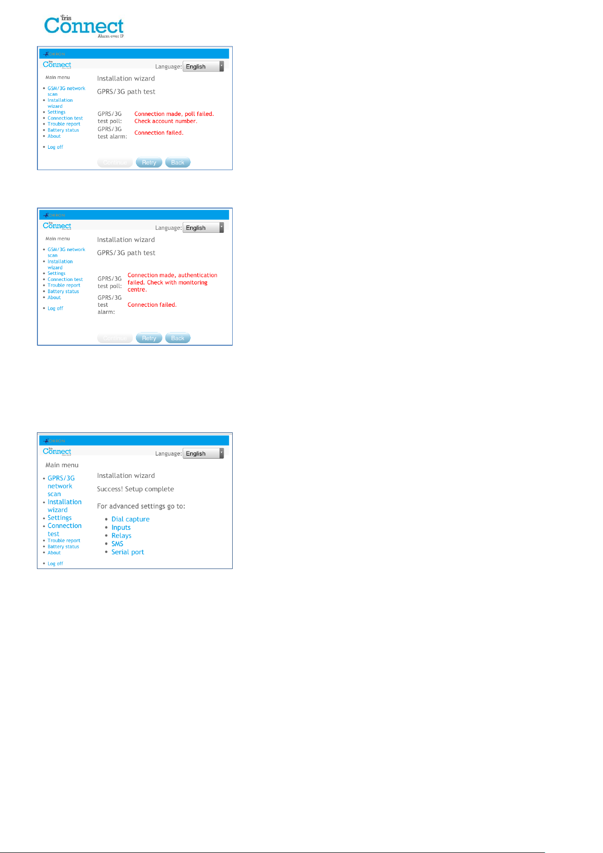
This indicates that the test poll call has reached the IRIS Secure Apps
system but the account number is not valid.
Check that the account number is programmed correctly.
Check with the monitoring centre that the account in IRIS Secure Apps is setup.
This indicates that the test poll call has reached the IRIS Secure Apps
system but the security keys do not match.
If the installer has recently defaulted or replaced the IRIS Connect dialler then the IRIS Secure Apps operator will
need to re-load the security key into the IRIS Connect dialler using the Allocator App.
After checking each of the configuration options reattempt to test the connection.
Setup Complete
The initial setup is now complete and for advance setting select the
‘Settings’ menu.
If all settings complete click ‘Log off’ to exit the web browser.
Once the Installation Wizard has been completed and any additional panel interface configuration setup via the
settings menu, check / configure the panel for the connection method being used if not already configured.
Page 22 of 40 IRIS Connect Series Engineering Manual Version 1.8
Page 23
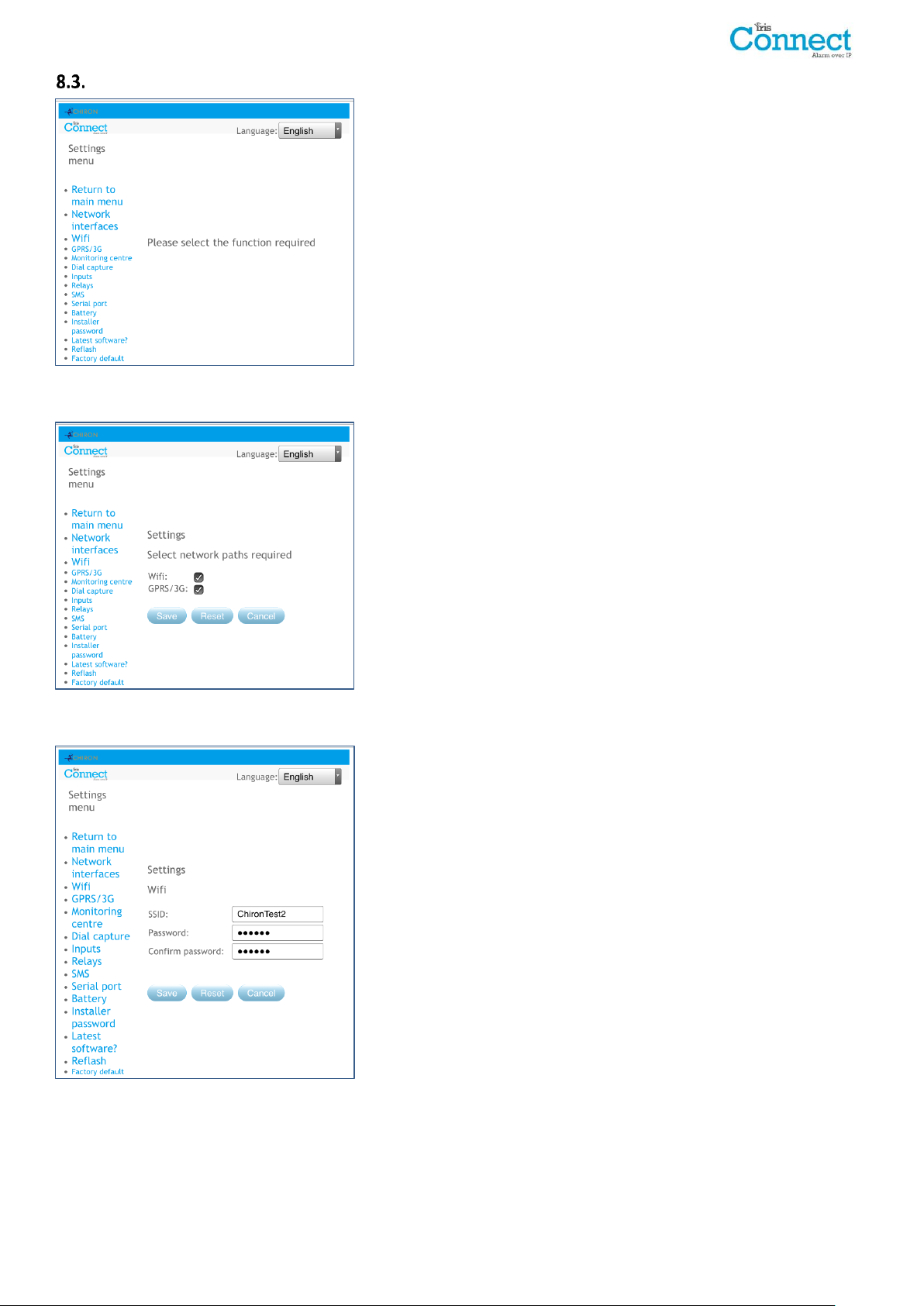
Settings
The Settings option is used to configure additional settings required for
installation or additional options that may be added at a later date.
Below is a detailed description of all of these options.
Network Interfaces (not selectable for IRIS Connect Solo)
This section allows the user to select the communication paths to be
used for polling / alarms on the dual path IRIS Connect Duo. There are
2 options as detailed below:
Wi-Fi
Wi-Fi
GPRS/3G (Machine to machine data ‘M2M’)
Setup the Wi-Fi network settings to connect to the customer Wi-Fi
network.
SSID (Wi-Fi network name)
Password
IRIS Connect Series Engineering Manual Version 1.8 Page 23 of 40
Page 24
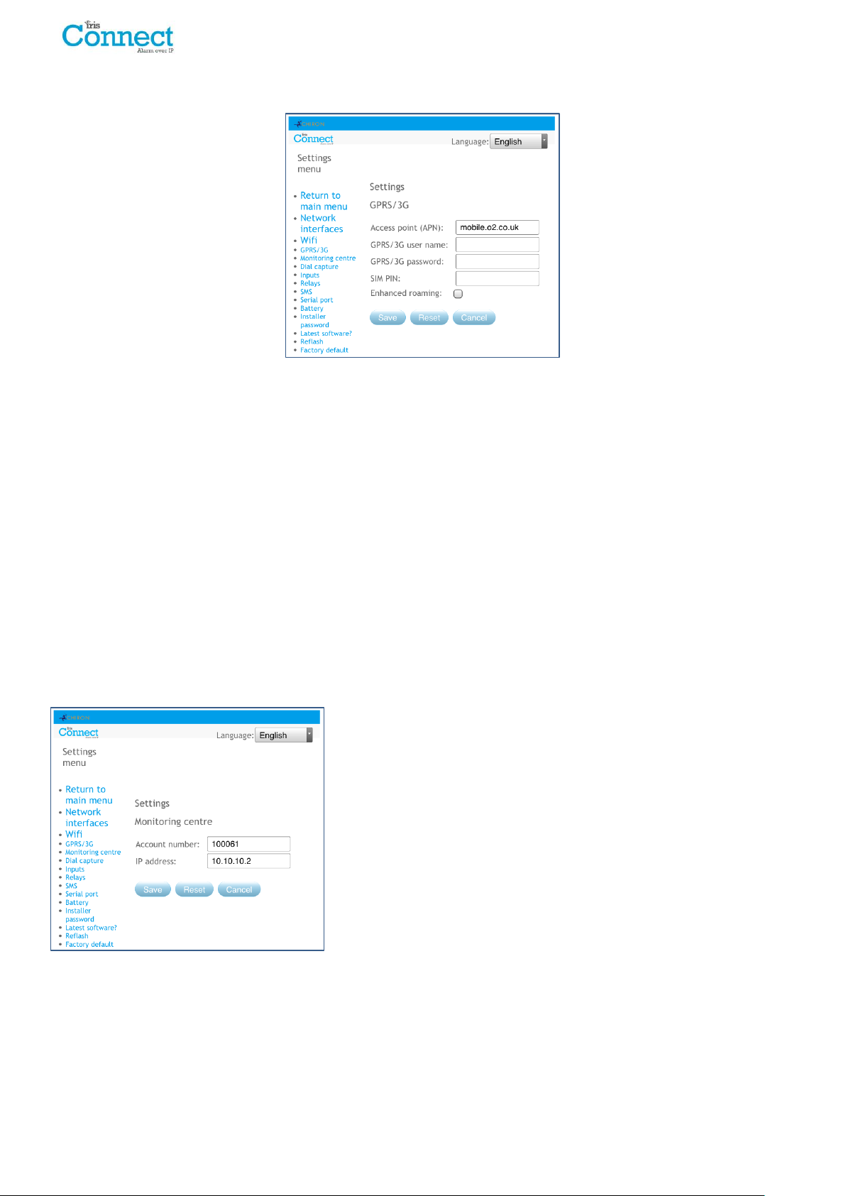
GPRS/3G Settings (IRIS Connect Due only)
This section allows the user to enter or view the GPRS/3G settings.
APN
GPRS/3G Access Point Name for the SIM card used.
GPRS/3G User Name
If none required then leave blank otherwise set the GPRS/3G user name for the SIM card.
GPRS/3G Password
If none required then leave blank otherwise set the GPRS/3G password for the SIM card.
SIM PIN
If the SIM card used has a PIN number set please enter here, normally this is disabled/blank.
Enhanced Roaming
This option enables an enhanced roaming feature when used with a roaming SIM.
Standard roaming SIMs will always attach to the preferred provider even if this has the weakest signal.
Enabling this option forces the GPRS/3G attachment to attach to the strongest signal base station. This allows the
IRIS Connect dialler to be even more resilient with the GPRS/3G network.
Monitoring Centre
Set the account name/number for the IRIS Connect unit on site, as
allocated by the monitoring centre.
Also setup the external IP address for the monitoring centre receiver
(polling engine).
Note: Only the primary/main ARC IP address needs to be entered on
the dialler as all backup or alternative IP addresses for the ARC are
downloaded to the IRIS Connect dialler on the first polling
communications.
Page 24 of 40 IRIS Connect Series Engineering Manual Version 1.8
Page 25

Dial Capture
Setup the dial capture panel interface.
Alarm override
Override the alarm panel’s account number and dialled number with those set in the IRIS Connect dialler.
Monitor panel interface
Sets the IRIS Connect dialler to monitor the dial port using the 18K resistor (as supplied in box) fitted across the A &
B terminals of the 2-wire analogue interface (telecoms module). Reports any status changes back to the monitoring
centre (ARC).
This resistor enables the dialler to detect cable faults and/or tampers and must be fitted at the alarm panel end of
the cable to function correctly. The monitoring centre will also need to enable the dial port monitoring from the IRIS
Secure Apps software to receive alarm notifications on this status.
Report poll fail
Tick to enable the dialler to drop the line voltage on the dial port connection if unable to poll over any configured
path to the monitoring centre. This allows the panel to detect and report locally on the keypad of the alarm panel
that it has a line fault, so the site has local indication of a communication failure (for EN standards).
Enable ring tone to panel
This feature is to allow the user to enable or disable the IRIS unit simulating the PSTN ring tone to the dial port while
the connection is being made. In most case this can be left as the default setting but if you are having issues with
alarms or remote service app connection (Upload/download), then you can try turning this off.
Euro ring cadence
If the alarm panel is expecting European or UK ring cadence to detect an incoming call, you can change the IRIS
Connect dialler to simulate either from Euro ‘ticked’ to UK ‘unticked’ (controls ring and ring tone cadence).
IRIS Connect Series Engineering Manual Version 1.8 Page 25 of 40
Page 26
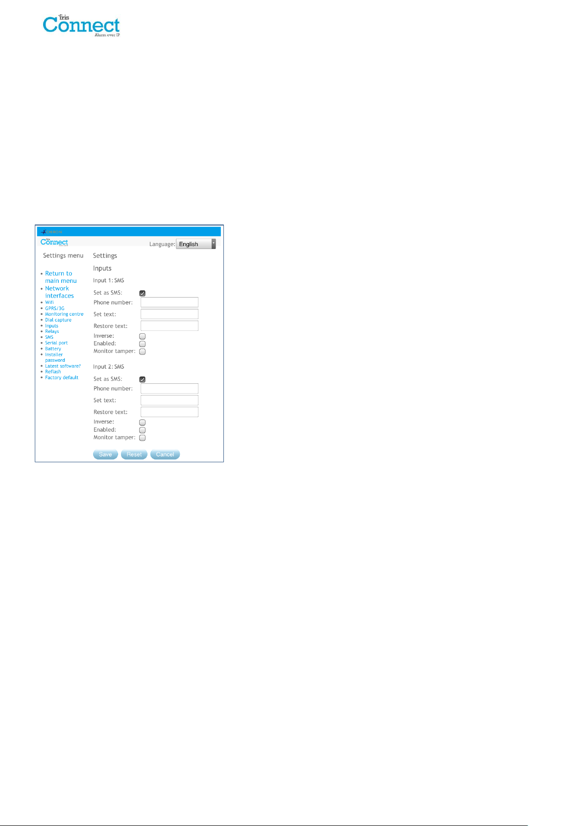
Inputs
Setup the Inputs (Pins) function between SMS messaging (IRIS Connect Duo only), SIA Alarm format or Contact ID
alarm format.
Note: One alarm format for the Pins (SIA or CID) can be selected and then setup individual pins to be SMS messaging
if required.
When changing the pin format between one of the alarm formats (SIA or CID) a warning message will be received to
indicate that all pins will be setup for this alarm format and returned to the default allocation shown below, as pins
cannot be setup to different alarm formats.
SMS (IRIS Connect Duo only)
On input ‘Set’ (open circuit) and input ‘Restore’ (close circuit) the IRIS Connect will send the configured SMS message
for the ‘Set’ or ‘Restore’ text, to the configured phone number.
Selecting SMS for the input format will display the following options to
configure for each pin as shown.
Phone no
Phone number used to send the SMS messages.
Set text / Restore text
Setup the ‘Set’ and ‘Restore’ messages to be sent to the entered phone
number. The maximum length for the text message is 24 characters.
Inverse
The function of the inputs ‘Set’ and ‘Restore’ can also be inverted to be
the opposite way round by ticking the ‘Inverse’ tick box. This will mean
that the ‘Set’ is now the closed circuit and the ‘Restore’ is open circuit.
Enable
Enable/disable each pin input with the ‘Enable’ tick box.
Monitor Cable
There is also the option to monitor the input for tamper which is
detailed in Section 7.7 “Pin Inputs”.
Page 26 of 40 IRIS Connect Series Engineering Manual Version 1.8
Page 27
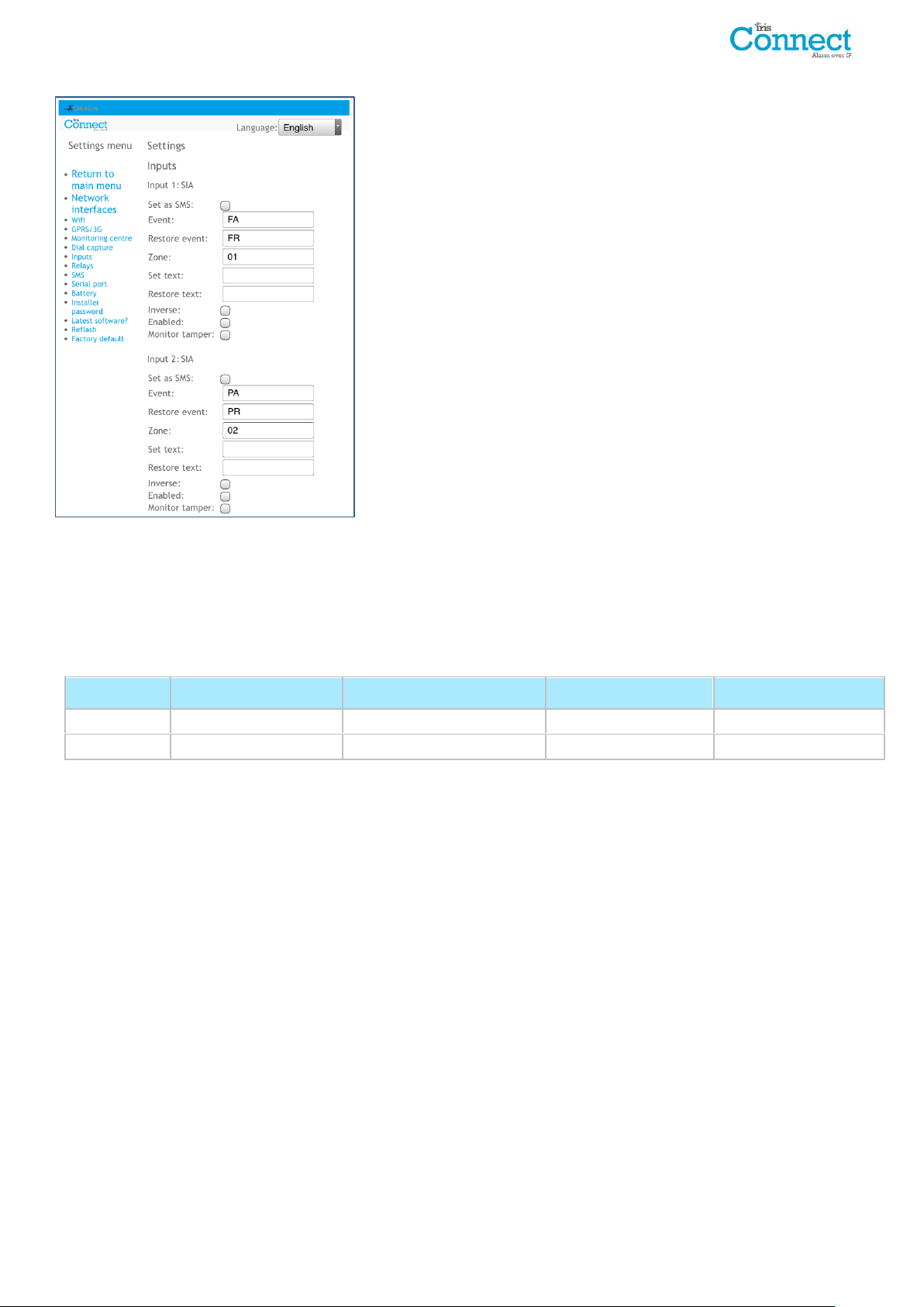
SIA
Pin Number
Event SIA code
Restore event SIA code
Zone Number
SIA event Description
1
NFA
NFR
01
Fire alarm zone 1
2
NPA
NPR
02
Panic alarm zone 2
Selecting SIA for the Inputs means that the inputs will send specific SIA
alarm protocol messages on the set event and restore for that input,
the options available as shown.
SMS
One input can be setup to be SMS by ticking the ‘Set as SMS’ and this
will allow setup of the SMS option as shown above.
Inverse Polarity
The function of the inputs ‘Set event’ and ‘Restore event’ can be
inverted to be the opposite way round by ticking the ‘Inverse’ tick box.
This will mean that the ‘Set event’ is now the closed circuit and the
‘Restore event’ is open circuit.
Enable
Enable/disable each pin input with the ‘Enable’ tick box.
Monitor Cable
There is also the option to monitor the input for tamper which is
detailed in Section 7.7 “Pin Inputs”.
Set text / Restore text
Setup the ‘Set / Restore’ message sent on the relevant event using the correct format as defined in SIA Format
protocol SIA DC-03-1990.01(R2003.10). At default this is pre-set to a specific SIA code and a zone number (see table
below). This can be modified for any event code and a text description added for each event which will be sent with
the SIA alarm code as with SIA level 3 alarm protocols. These can be no longer than 15 characters in total.
Default SIA Set/Restore event codes for Inputs:
IRIS Connect Series Engineering Manual Version 1.8 Page 27 of 40
Page 28
Pin
Number
Contact ID
event code
Zone
number
Group
number
Contact ID event description
1
110
001
00
Fire alarm zone 1
2
120
002
00
Panic alarm zone 2
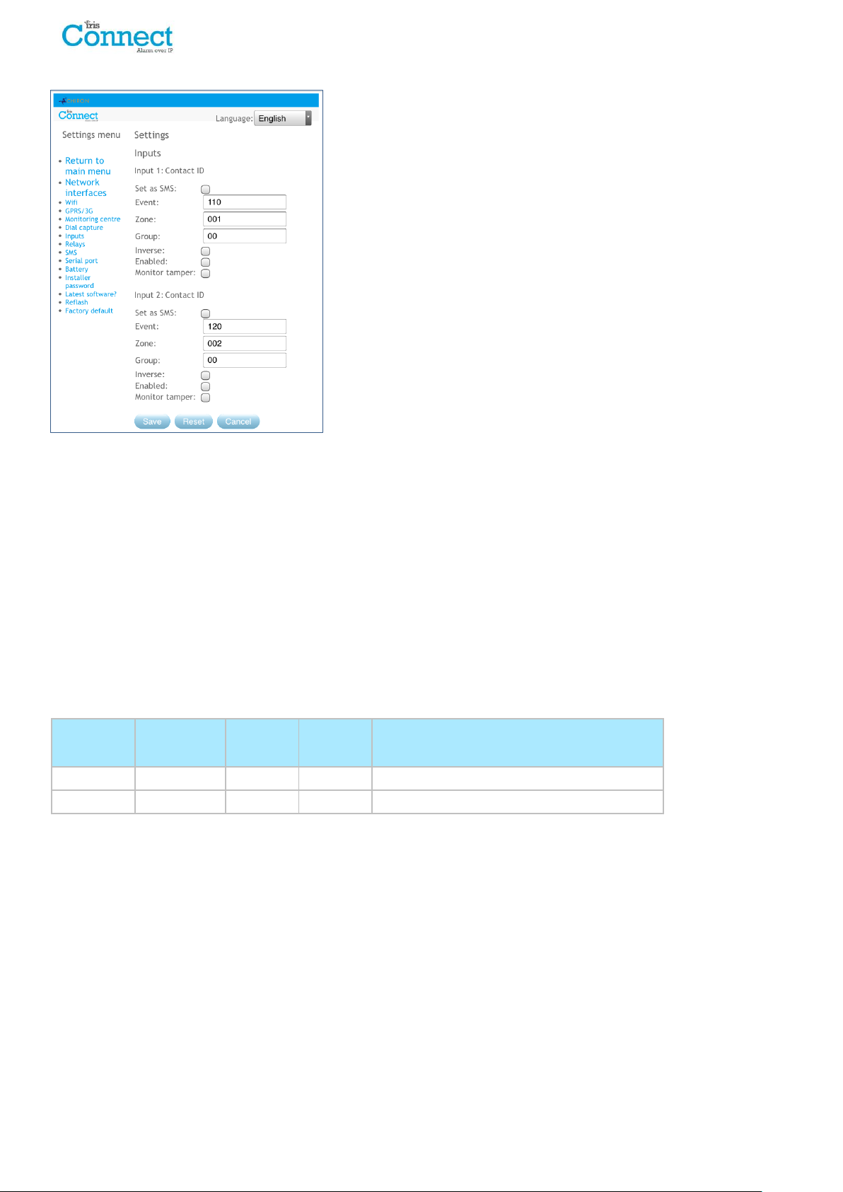
CID (Contact ID)
Selecting CID for the inputs means that the inputs will send a specific
Ademco® alarm protocol messages which will include an event code,
zone and group number, on the event and restore for that input. The
following options available are shown below:
SMS
One input can be setup to be SMS by ticking the ‘Set as SMS’ and this
will allow setup of the SMS option as shown above.
Inverse Polarity
The function of the inputs ‘Event’ and ‘Restore’ can be inverted to be
the opposite way round by ticking the ‘Inverse’ tick box. This will mean
that the ‘Event’ is now the closed circuit and the ‘Restore’ event is open
circuit.
Enable
Enable/disable each pin input with the ‘Enable’ tick box.
Monitor Cable
There is also the option to monitor the input for tamper which is
detailed in Section 7.7 “Pin Inputs”.
Event
Enter the Event code (3 digits 0-9) for this input for example: 110 = Fire.
To determine which event code is to be used please refer to the Digital Communication Standard -
Ademco® Contact ID Protocol - for Alarm System Communications SIA DC-05-1999.09
Zone
Zone number (Event reports) or User # (Open / Close reports) (3 digits 0-9).
Use 000 to indicate that no specific zone or user information applies.
Group
Group or Partition number (2 digits 0-9).
Use 00 to indicate that no specific group or partition information applies.
Default CID Set/Restore event codes for Pin inputs:
Page 28 of 40 IRIS Connect Series Engineering Manual Version 1.8
Page 29
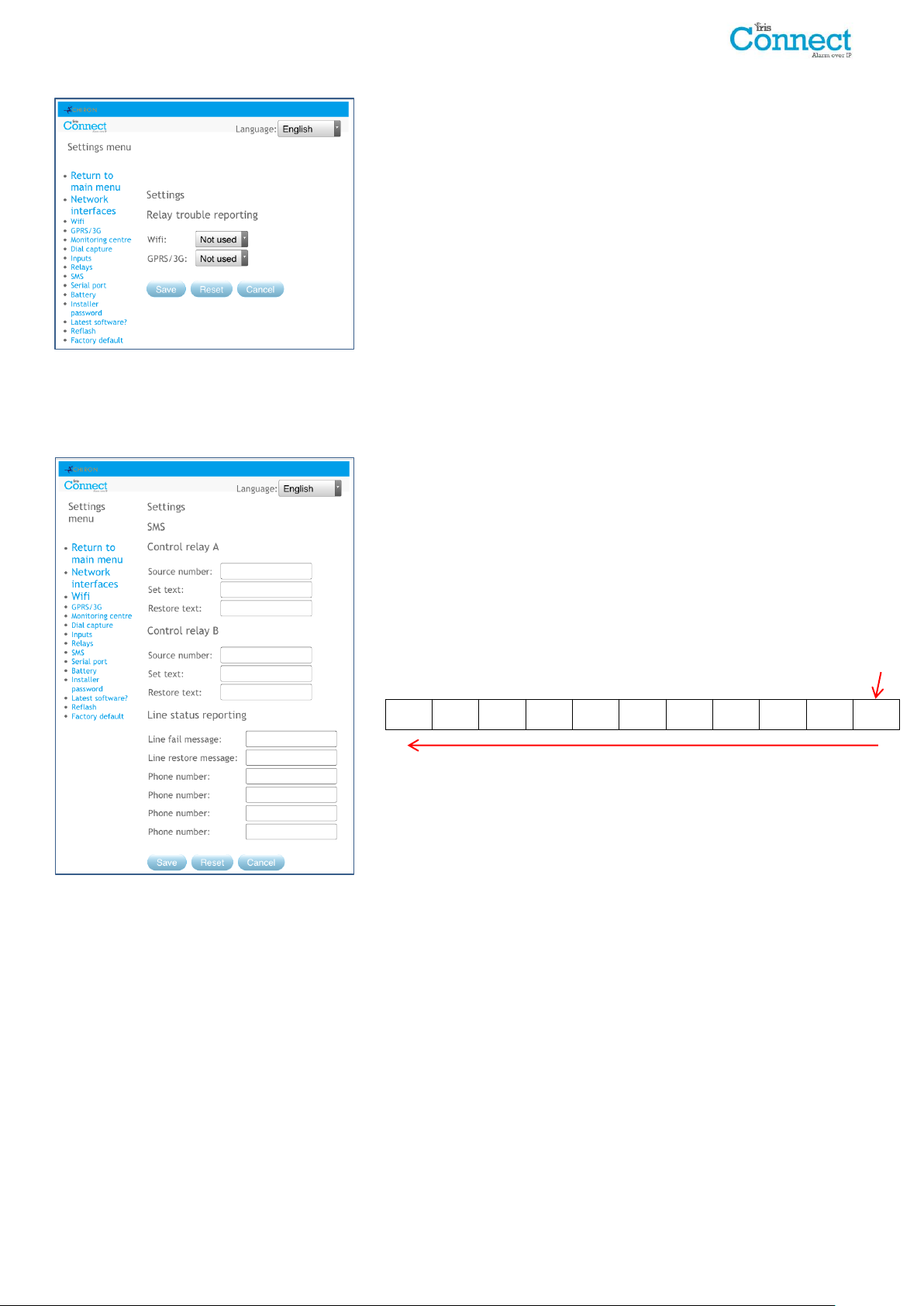
Relays
0 7 8 9 0 1 2 3 4 5 6
LSB
It is possible to enable or disable the IRIS Connect dialler toggling the
state of the relays to indicate communication path failures. This is
intended to signal failures back to the panel inputs so the site has local
indication of a communication failure (for EN standards).
SMS
The IRIS Connect dialler allows each relay to be activated or deactivated by a predefined SMS message from a mobile
phone.
Source number
Sets which calling device (mobile phone) is allowed to control the relay
with the relevant SMS message. This is done by using the Calling line
number (CLI) on the SMS and comparing this with the number entered.
The dialler will start the comparison from the least significant digit and
then work backwards as shown below:
For the example we will use the phone number 07890123456, please
confirm what CLI number is being received by using a mobile phone to
receive the call, this will allow you to see the incoming CLI number.
Starting from the LSB ‘6’ you can work backwards to compare the CLI
number so for example you can enter a number of 56. This will allow all
phone numbers with a CLI ending in 56.
Leaving the source number blank will allow any mobile number to set
or restore the relay as long as the SMS text matches.
Set text
Sets the SMS text message required to open the relay, note this is case sensitive.
Restore text
Sets the SMS text message required to close the relay, note this is case sensitive.
Line status reporting
The IRIS Connect dialler can send SMS messages to indicate communication / line faults via the GSM/3G network.
There are 4 SMS phone numbers that can be set up for sending SMS messages, for line fail/restore reporting.
IRIS Connect Series Engineering Manual Version 1.8 Page 29 of 40
Page 30
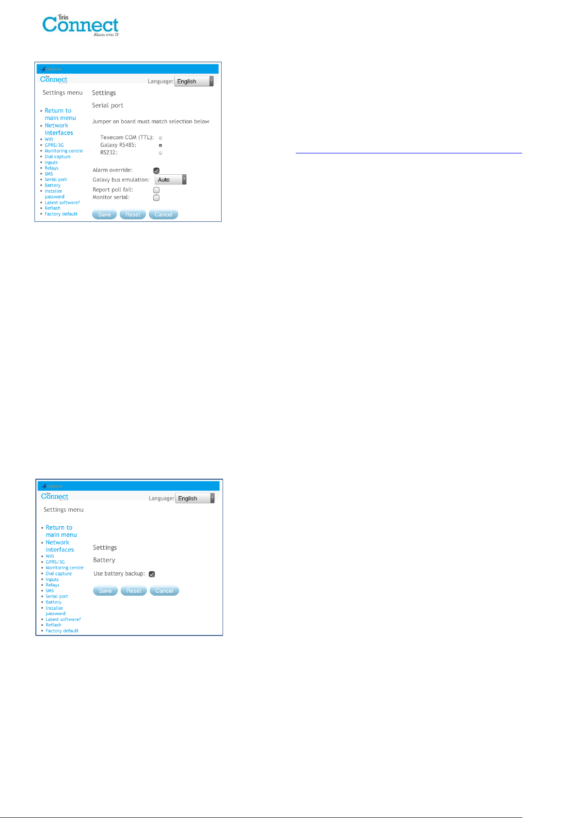
Serial Port
This allows you to setup the serial port for Texecom Premier
Connections, Honeywell Galaxy RS485, or Normal modes. By default
this is setup for Texecom emulation. For more information on the
connection and setup please refer to the panel installation manual
available from http://www.chironsc.com/downloads_security.html.
Note: It is important to ensure that jumper link on the ‘Serial
selection header’ is on the same selection.
Alarm override
Override the alarm panel’s account number and dialled number with those set in the IRIS Connect dialler.
Galaxy bus emulation
This option allows the selection of the Honeywell Galaxy RS485 bus module that is emulated to the Galaxy control
panel. By default this is set to AUTO (Automatic assigned) which will try the external Ethernet module first and if this
is not seen then the external PSTN, and finally the external serial modules. This allows for backwards compatibility to
older Galaxy panel software versions that do not support the Honeywell Ethernet module (Galaxy Classic below
version 4.00).
Report poll fail
Set the IRIS dialler to stop responding to the serial commands if polling has failed. This will then indicate the failure
back to the alarm panel. This allows the site to have local indication of a communication failure (for EN standards).
Monitor Serial
Set the IRIS dialler to monitor the serial port for activity and report any status change back to the monitoring centre
(ARC).The monitoring centre will also need to enable the serial port monitoring from the IRIS Secure Apps software
to receive alarm notifications on this status.
Battery
If installing the IRIS Connect without batteries then this option should
be unticked.
Page 30 of 40 IRIS Connect Series Engineering Manual Version 1.8
Page 31
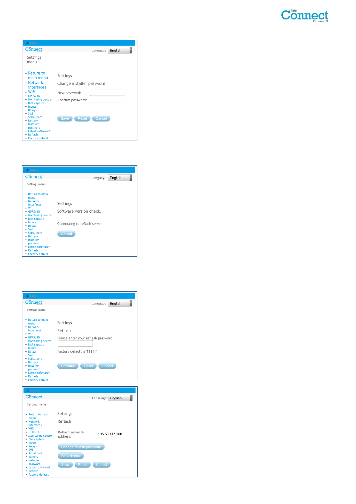
Installers Password
Latest software?
When the user first accesses the Installer menu, the Installers
password is required, which is defaulted to ‘111111’. During
installation it will be necessary to change the password as required for
EN50136-2.
This password can be changed again if required with this setting. When
a new password will need to be entered and confirmed.
Check via the Wi-Fi or GPRS connections to the Chiron Reflash server if
there is a later software release available.
Reflash
The option will be given to reflash the unit to the latest version available from the Chiron reflash server.
On first entry to the reflash option, which could be during installation
or maintenance, the password will need to be changed as required for
EN50136-2.
Otherwise the reflash password that has been configured for this unit
will be requested to be entered.
A reflash to update the IRIS Connect dialler to the latest software
version can be initiated and the options are shown below:
Reflash server IP address
The default reflash IP address is the Chiron reflash server setup on an IP
address 195.59.117.164 which is available 24/7 for connections, and
kept up to date with the latest software available.
There are cases where a customer will only open their network to
communicate back to the monitoring centre (network/IP address), and
in some cases the monitoring centre has their own reflash server
installed. This option allows the sending of a reflash request to an
alternate IP address.
Change reflash password
This password can be changed again if required with this setting.
Reflash Now
Initiate the reflash to the reflash IP address and will bring up a status
window to indicate progress.
IRIS Connect Series Engineering Manual Version 1.8 Page 31 of 40
Page 32
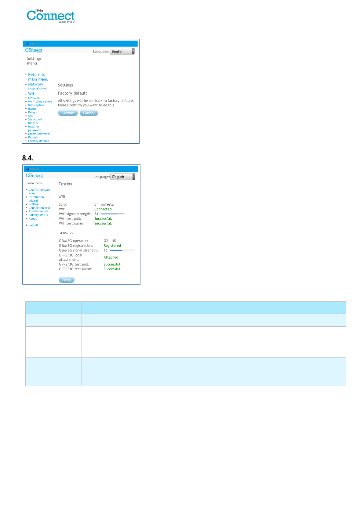
Default All
Testing
Results and explanations
SSID
Indicates the configure Wi-Fi network.
WiFi
Connected: Confirms the dialler is connected to the Wi-Fi network.
Not Connected: The dialler is currently not connected to the Wi-Fi network; check the Wi-Fi
network details and Wi-Fi Router.
Wifi signal
strength
Indicates current Wi-Fi signal strength which is recommended to be above 20 or higher for
reliable communications; if below the minimum require look to either move the dialler to get
better coverage or fit an external Wi-Fi antenna.
Test
Completely resets the IRIS Connect dialler to manufacturing defaults.
The test menu allows checking of all current enabled communication
paths, and will test both polling and alarms.
The current connections statuses for all paths can also be seen.
When first accessing the test menu “Test in progress” will be displayed.
The dialler will start to test the communication paths configured.
Once the tests are complete the following possible outcomes are
available as shown in the table below.
Page 32 of 40 IRIS Connect Series Engineering Manual Version 1.8
Page 33

Testing
Results and explanations
WiFi test Poll
Successful: Dialler successfully polled to the monitoring centre (ARC) IRIS Secure Apps system
over the Wi-Fi network.
Polling disabled: Configured not to poll over the Wi-Fi network; check ARC IP address and
account number are still entered.
Connection failed: Failed to connect to ARC over the Wi-Fi network; check the ARC IP address
is correct, confirm Wi-Fi router External WAN connection and firewall setup.
Connection made, poll fail: Connected to the ARC IRIS Secure Apps but was rejected; check
correct account number has been setup at ARC IRIS Secure Apps and that correct account
number is entered in dialler.
Connection made, authentication failed: Connected to the ARC IRIS Secure Apps but was
rejected due to invalid security key; check correct account number entered in dialler. If a
replacement dialler was installed the ARC will need to perform a ‘Reload Parameters’ on the
IRIS Secure Apps web interface.
Wifi test alarm
Successful: Wi-Fi SIA level 3 test alarm reported successfully to ARC.
Connection failed: Failed to send alarm to ARC over Wi-Fi network; check with ARC.
GSM/3G
Operator
Indicate the current GSM/3G operator’s base station connected to, could be different from
SIM card if a roaming SIM for example.
GSM/3G
registration
Registered: Dialler is connected to the GSM/3G network.
Not registered: The dialler is not registered to the GSM/3G network; check SIM card is
enabled and inserted correctly into the SIM card holder, also check antenna and signal
strength are connected and above minimum signal strength.
GSM/3G signal
strength
Indicates current signal strength, which is recommended to be above 10 for reliable
communications; if below the minimum required either move the dialler or antenna to gain
better coverage or fit an external high gain GPRS/3G antenna.
GPRS/3G local
attachment
Attached: Dialler has a GPRS/3G attachment to the local base station
Not Attached: Dialler GPRS/3G not attached to the local base station; check with setup with
SIM card provider.
GPRS/3G test poll
Successful: Dialler successfully polled to the monitoring centre (ARC) IRIS Secure Apps system
over the GPRS/3G network.
Polling disabled: Configured not to poll over GPRS/3G network; check ARC IP address and
account number are still entered.
Connection failed: Failed to connect to ARC over GPRS/3G network; check the ARC IP address
is correct, and confirm SIM card is enabled for GPRS/3G machine to machine data (M2M) with
the SIM card provider.
Connection made, poll fail: Connected to the ARC IRIS Secure Apps but was rejected; check
correct account number has been setup at ARC IRIS Secure Apps and that correct account
number entered in dialler.
Connection made, authentication failed: Connected to the ARC IRIS Secure Apps but was
rejected due to invalid security key; check correct account number entered in dialler, and if a
replacement dialler was installed the ARC will need to perform a ‘Reload Parameters’ on the
IRIS Secure Apps web interface.
GPRS/3G test
alarm
Successful: GPRS/3G SIA level 3 test alarm reported successfully to ARC.
Connection failed: Failed to send alarm to ARC over GPRS/3G network; check with ARC.
IRIS Connect Series Engineering Manual Version 1.8 Page 33 of 40
Page 34
Trouble Reported
Explanation
Disconnected from Wi-Fi network
The dialler is currently not connected to the local Wi-Fi network;
Check Wi-Fi connection details and Wi-Fi router.
No polling over Wi-Fi
Unable to poll via the Wi-Fi network to the monitoring centre’s (ARC) IRIS
Secure Apps system; check ARC IP address, confirm Wi-Fi router external
WAN connection and firewall setup.
GPRS/3G not registered with base
station
Not able to register to the GSM/3G network; normally means the SIM card
has been disabled, check with SIM provider.
No polling over GPRS/3G
Unable to Poll via the GPRS/3G network to the monitoring centre’s (ARC)
IRIS Secure Apps system; check ARC IP address, SIM card is enabled for
GPRS/3G machine to machine data (M2M).
SIM Card not fitted
SIM card not being seen in the IRIS unit; check SIM fitted and that
connection is ok.
SIM PIN required
SIM card has been setup for a PIN number and no SIM PIN entered in
configuration; Confirm the correct SIM PIN with the SIM provider and
enter.
SIM PIN error
Current SIM PIN entered in the configuration is invalid; confirm correct SIM
PIN with SIM provider and confirm entered correctly.
No Polling
The dialler is unable to poll over any path; check correct ARC IP address
entered, and communication paths setup.
Dial capture port tamper
Dial port configured to monitor dial port and sense resistor not being
detected (18K). Check cable/resistor connections.
Tamper on inputs
Indicates that the dialler has been set to monitor for tampers and is in an
open or short circuit tamper condition. Check cable/resistors connections.
Serial port fault
The dialler is setup to monitor serial but is seeing no activity on the serial
connection; check setup of the dialler / panel and physical connection.
Case tamper
Either the front or back case tamper has been triggered. Check the case
mounting and that the lid is correctly fitted. If all fitted and correctly
mounted the tamper will automatically restore.
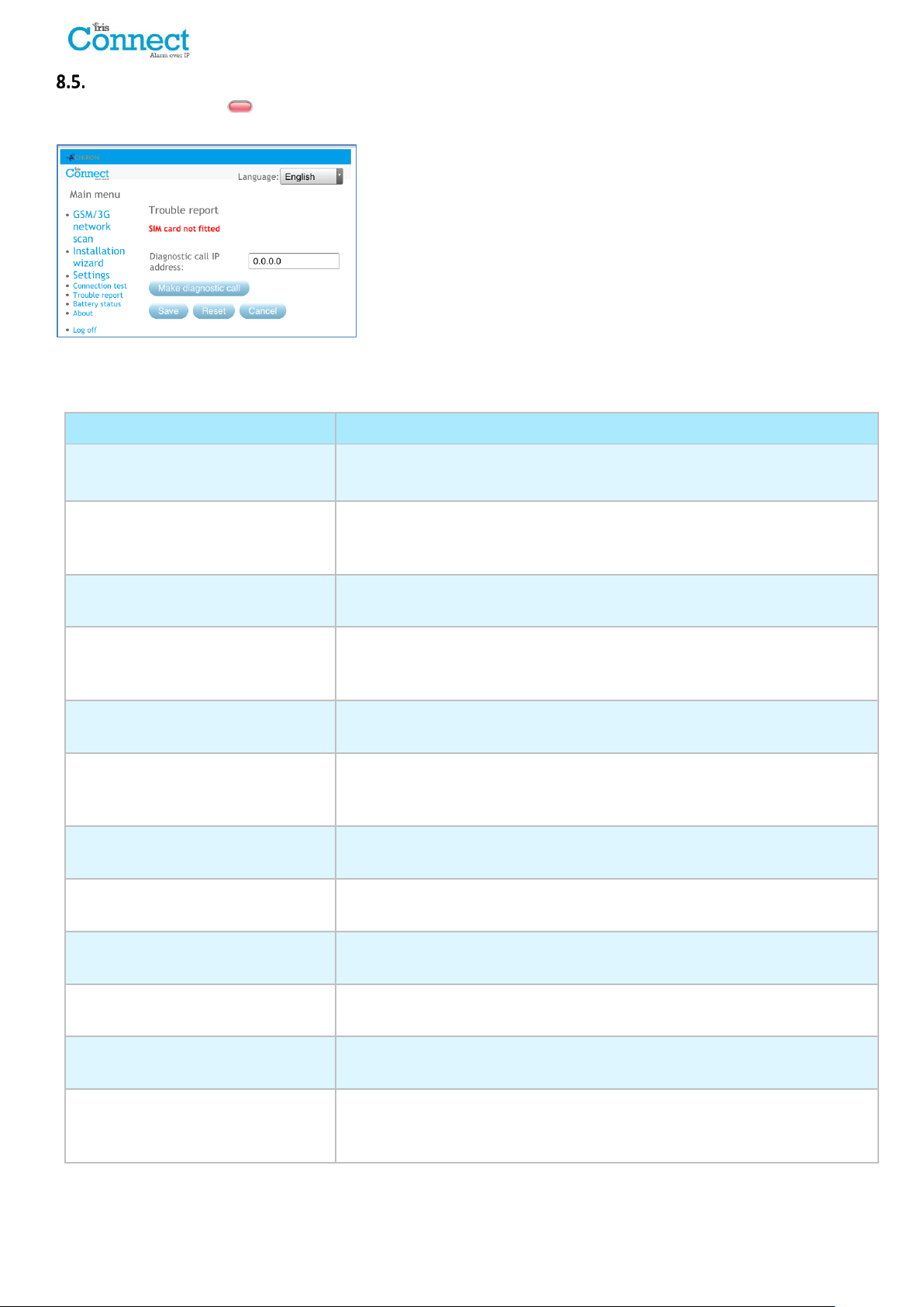
Trouble Report
When the SYS LED is red the dialler has some trouble events being reported. You can view these in more detail
by accessing the ‘Main menu – Trouble report’ option.
The Trouble report menu indicates what the current system troubles
are and below is an explanation of all possible events.
You also have the option to setup and initiate a remote diagnostic call
back over an IP connection to the IRIS Toolbox software. This allows
the user or technical support team to run diagnostic/test and help to
identify any issues with setup or connections.
The remote diagnostic call allows you to make an outbound TCP/IP call
using TCP/IP port number 51292 to a senior technician / Chiron
Technical support with a PC/laptop running the IRIS Toolbox software.
This will then allow them to check setup and run diagnostic remotely
to investigate any issues.
Page 34 of 40 IRIS Connect Series Engineering Manual Version 1.8
Page 35
Trouble Reported
Explanation
Input fail to communicate
A dialler input has been triggered and this event has failed to be
communicated to the ARC. Check all communication paths are working and
configuration is correct; also check with the ARC that they have no known
issues with received alarms (E.G. IRIS Poll engine IP link down).
Replace Batteries
The batteries are unhealthy and need to be replaced.
Eeprom
The dialler has a possible hardware issue and is unable to see the Eeprom.
The Eeprom stores all local parameters for protection against power failure.
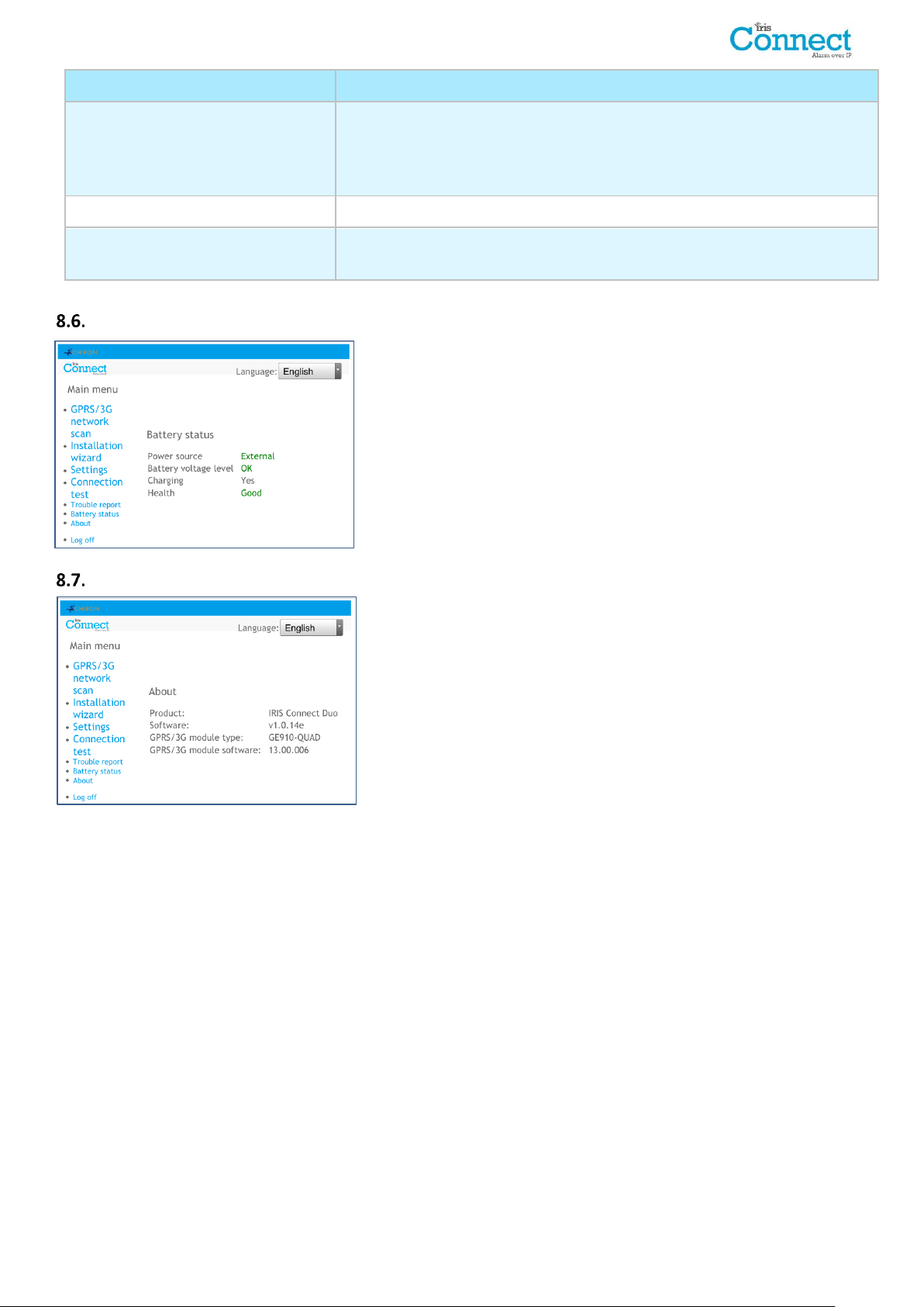
Battery Status
The IRIS Connect dialler allows installers to check the current battery
status and will indicate any issues with the batteries.
About
IRIS Connect software version, GPRS/3G software version are
displayed.
IRIS Connect Series Engineering Manual Version 1.8 Page 35 of 40
Page 36
9. Maintenance
The dialler should be inspected on a yearly basis. At each inspection please perform the following:
Confirm the status of the IRIS Connect unit.
Clear any faults on the dialler.
Check battery status and replace if below required level.
Reflash IRIS Connect software to latest version.
Test the configured communication paths (Wi-Fi / GPRS / 3G).
Perform full test of alarms from the alarm panel and confirm these are received at the monitoring centre.
The IRIS Connect will give a visual indication of the current system status via the SYS LED on top left side of case. If
this is green the dialler is all reporting ok, if red the dialler has some trouble events being reported.
To further investigate any faults or to perform checks, the IRIS Connect dialler gives engineers the option via the
Web Browser screen, to see current faults, reflash to latest software and perform communication path checks.
To initiate the Wi-Fi connection engineers will need to ensure the IRIS Connect has power and then remove the front
cover via the release clips x 2 located at the bottom on the dialler, then press the button labelled AP on the IRIS
Connect.
When the AP button is pressed the SYS LED will flash ‘blue’ to indicate AP mode has been activated and is awaiting a
connection. You now have a 30 minute time window to search and find the IRIS Connect using either a smart phone,
tablet or laptop’s Wi-Fi connect search function.
An ‘IRIS’ network should appear. Please connect to this which should turn the SYS LED solid ‘blue’ and using your
web browser connect to the IRIS Connect web interface by browsing to ‘iris.local’.
Note: If engineers have never used / connected to an IRIS Connect before it may be necessary to download /
install some application / software to connect via the Wi-Fi Web browser, please refer to Section 7.9
“Configuration – Configuration via Web Browser using Wi-Fi connection”.
Enter the installer code (should be noted somewhere, possibly installation notes) and then click Logon.
Engineers will now be in the Main Menu and can perform the following checks:
Confirm Current Status
If the SYS LED is green then the current status is being reported as ok go straight to Section 9.2 “Checking
battery status”. If the SYS LED is red which indicates the dialler has a trouble reported go to the option for
“Trouble report”. This will redirect the engineer to connect the IRIS Connect Web browser interface via the Wi-Fi
network.
Once connected via the Wi-Fi network the engineer can then check the current system troubles being reported via
the “Trouble report” menu. Please refer to Section 8.5 “Trouble report” for further details on these events.
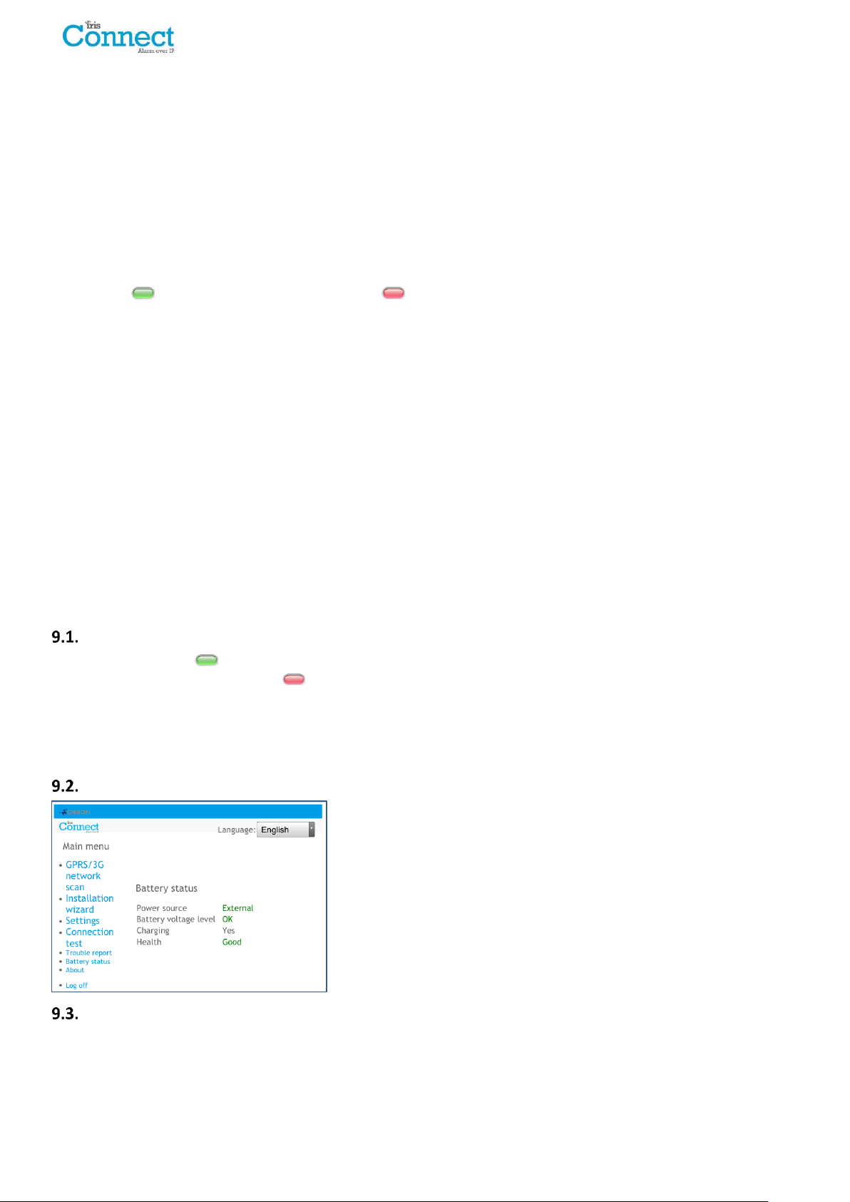
Checking Battery Status
The IRIS Connect dialler allows engineers to check the current battery
status and will indicate any issues with the batteries.
Go into the “Battery Status” option and confirm that the Health Status
is showing as “Good” before leaving site.
Replacing Batteries
If the backup batteries (optional) have been fitted then these should be replaced every two years.
Page 36 of 40 IRIS Connect Series Engineering Manual Version 1.8
Page 37

Check Software Version / Reflash
Go to the settings menu and then select “Latest software?” this will then check with the Chiron Reflash server if
there is a later version available.
If a later version is available the engineer will see the option to press the reflash button.
On first entry to the reflash option which could be during installation or maintenance, the engineer need to change
the password as required for EN50136-2 compliance. Please record the password on the installation documentation.
The reflash will take up to 15 minutes if via GPRS/3G and approximately 2 minutes with the Ethernet connection. Once
completed the dialler will reboot and switch to the new software. All configurations are saved and there is no need to
reconfigure the IRIS Connect dialler.
Communication Paths Checks
The engineers can test the communication paths for both polling and alarm communications using the ‘Connection
Test’ option in the Main Menu. This will direct engineers to connect the IRIS Connect Web browser interface via the
Wi-Fi network if they are not already connected and perform communication path checks for each path configured.
See Section 8.4 “Test” for more details.
Test Alarm Panel Alarms and Communication to ARC
Depending on the monitoring centre (ARC) engineers will now be required to perform alarm test and possibly other
tests to the ARC. Before the engineer leaves site get confirmation from the ARC that all is working correctly.
IRIS Connect Series Engineering Manual Version 1.8 Page 37 of 40
Page 38
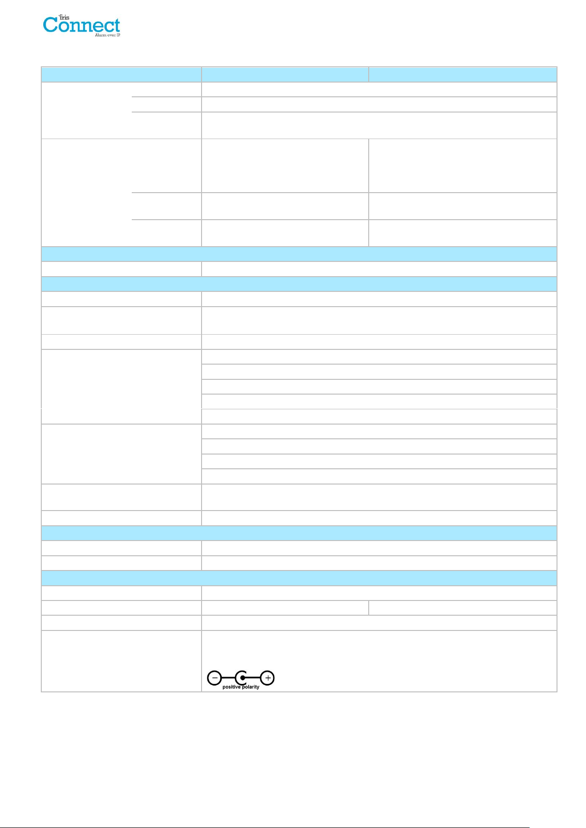
Transmission paths
IRIS Connect Solo
IRIS Connect Duo
Wi-Fi
Standard
IEEE 802.11 b/g
Connection
SMA socket for Wi-Fi antenna connection
Connection
fault detection
Loss of association/data
GPRS/3G
(4G/CDMA optional
on request)
Standard
Dual band GSM
900/1800 MHz
Dual band UMTS
900/2100 MHz
Connection
SMA socket for GPRS/3G antenna
connection
Connection
fault detection
Loss of registration with network
IP
TCP ports (outbound)
53165 (Alarms & Polling), 51292 (Diagnostic & Reflashing), 10001 (Upload/Download)
Alarm transmission
Interface to monitoring centre
IRIS Secure Apps or IRIS Management suite via EN 50136-2 pass-through mode
Dial capture interface to alarm panel
Two wire interface via RJ45 socket & terminal block
Note: Cabling must not exceed 3 meters
Serial interface to alarm panel
RS485, TTL, RS232 Note: RS232 cabling must not exceed 3 meters
PIN Inputs interface to alarm panel
Maximum input voltage range 0V to +24V
Input ‘low’ (alarm) threshold < 1V
Input ‘high’ (restore) threshold > 2V
Internal pull-up impedance 10K to 3.3V supply
Note: Cabling must not exceed 3 meters
Alarm protocols
SIA (level 1 to 3) reference SIA DC-03-1990.01(R2003.10)
Contact ID reference SIA DC-05-1999.09
Fast format (Scancom) for dial capture and serial connections
Robofon (Dial capture only)
Tamper detection reporting to
monitoring centre
Dial capture interface, Lid & back tamper, Serial interface, Pin inputs
Fault reporting to monitoring centre
External power supply fail, low battery, Transmission interface/path fault
Relay outputs
Maximum operating voltage
24V DC
Maximum current rating
100mA DC
Power supply
Supply voltage
9V to 17V DC
Typical current
78mA @ 12V DC
83mA @ 12V DC
Maximum current
1A @ 12V DC
Recommended external PSU
12V DC 1A 12 Watt DC Barrel 2.5mm centre
Note: For Radio & Telecoms Terminal Equipment Directive the power cable needs to
be no longer than 3 meters in length
10. Specifications
Page 38 of 40 IRIS Connect Series Engineering Manual Version 1.8
Page 39
Power storage
Storage device type
4 x AA NiMH rechargeable batteries
Storage device capacity
2000mAh
Storage device time to recharge to
80% capacity
32 hours
Storage device – voltage at which
fault is reported
4.5V DC
Storage device – voltage at which
fault is restored
5V DC
Storage device – over voltage
protection triggered
6.5V DC
Storage device – deep discharge
protection
4V DC
Environmental
Operating temperature range
-10°C to 55°C
Operating humidity range
95% max., non-condensing
Weights and Dimensions
Physical dimensions (L x W x D)
11.5cm x 17.5 cm x 4.5 cm
PCB weight
400 grams
Fully packaged weight
600 grams
SELV:
SELV (Safety Extra-Low Voltage) is defined as a secondary
circuit which is so designed and protected that under normal
and single fault conditions the voltage between any two
accessible parts does not exceed a safe value (42.4V peak or
60V dc maximum)
Safety
Care should be taken when connecting telecommunications equipment to ensure only like interfaces are connected
to avoid safety hazards.
The interfaces on the IRIS Connect have the following safety classifications:
Dial capture interface: SELV suitable for connection to the TNV interface of single line telecommunications
equipment such as telephones, alarm panels, etc.
Power Interface: SELV for connection to a DC supply
Inputs: SELV for connection to alarm output pin.
Conformance
European Directives
The IRIS Connect complies with the following European Directives:
1999/5/EC (Radio & Telecoms Terminal Equipment Directive)
2006/95/EC (Low Voltage Directive)
2004/108/EC (Electromagnetic Compatibility Directive)
EN50131, EN50136 (VdS Certified)
The dialler is compliant with the requirements of European Standards:
EN50131-1: 2006 & EN50131-10: 2014
EN50136-1: 2012 & EN50136-2: 2013
Security Grade 2
ATS-SP6 over Wi-Fi, ATS-SP5 over GPRS/3G, ATS-DP4 (IRIS Connect Duo)
Environmental Class II
IRIS Connect Series Engineering Manual Version 1.8 Page 39 of 40
Page 40

The future of security, secured
IP by security professionals, for the professional security industry
Installation and Service Engineer Support Telephone: +44 871 977 1133
(Calls are charged at 13 pence per minute plus your phone company’s access charge)
Sales Enquiries: +41 435 080 870
Email: [email protected]
www.chironsc.com
Chiron Security Communications AG
Bahnhofstrasse 30
6300 Zug
SWITZERLAND
The information contained is supplied without liability for any errors or omissions. No part may be reproduced or used
except as authorized by contract or other written permission. The copyright and foregoing restriction on reproduction
and use extend to all media in which the information may be embedded.
© 2016 Chiron Security Communications AG
 Loading...