

Page 1

RREEVV33..33 PPaaggee 11,, 1166 ppaaggees
s
CSM3510 User Manual
REV3.3
Address: Shenzhen Nanshan District City Nanhai Road No.1079 Garden City Digital
tower A9 floor
Postcode: 518067
Company phone: + (86755) 86169257
Fax:+(86 755)86169057
Company website: www.chipsea.com
Wechat account:chipsea
Wechat QR code:
Page 2
CSM3510
RREEVV33..33 PPaaggee 22,, 1166 ppaaggees
s
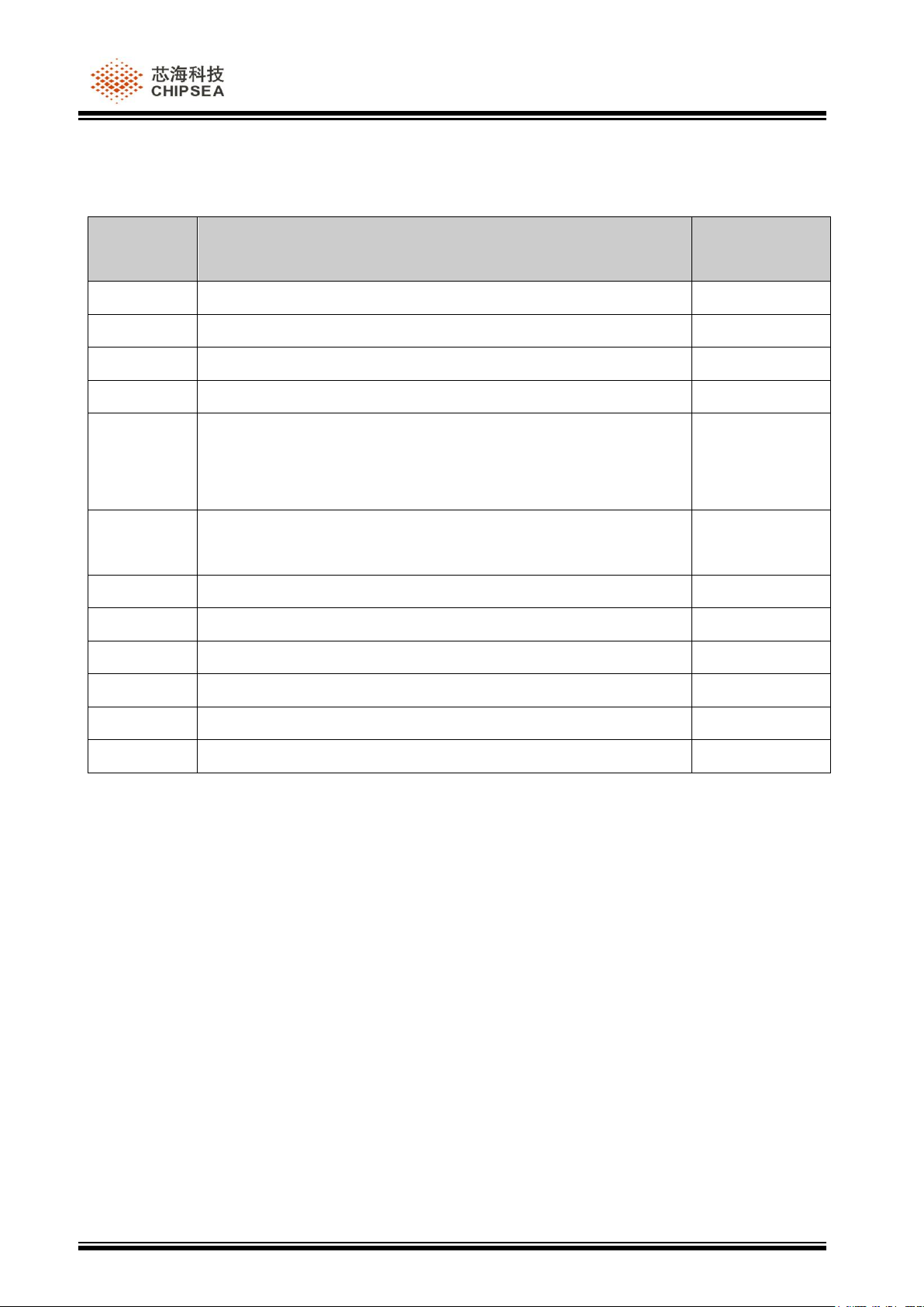
Verison
history
Content changed
Verison date
REV1.0
Initial version
2014-8-12
REV2.0
Add dimension figure and update some content
2014-11-26
REV3.0
Add SPI interface description
2014-12-04
REV3.1
Modified SPI end flag byte
2014-12-05
REV3.2
Modify power test results
Add broadcast MAC address
Add name modifing instruction
2015-01-29
REV3.3
Modify the data transmiting instruction
Removed the SPI instruction
2015-07-29
VERISION HISTORY
Page 3

CSM3510
RREEVV33..33 PPaaggee 33,, 1166 ppaaggees
s
DIRECTORY
VERISION HISTORY ...................................................................................................................... 2
DIRECTORY ..................................................................................................................................... 3
1 PRODUCT ................................................................................................................................... 4
1.1 FUNCTION DESCRIPTION .......................................................................................................... 4
1.2 MAIN CHARACTERISTICS ......................................................................................................... 4
1.3 POWER CONSUMPTION ............................................................................................................ 4
1.4 INTERFACE DEFINITION ........................................................................................................... 5
1.5 PACKAGE SIZE CHART ............................................................................................................. 5
2 MODULE OPERATION ........................................................................................................... 6
2.1 UART INTERFACE .................................................................................................................. 6
2.1.1 Serial baud rate................................................................................................................ 6
2.1.2 Packet format .................................................................................................................. 6
2.1.3 Control instruction introductioin .................................................................................... 6
2.1.4 Response instruction ..................................................................................................... 10
2.1.5 Send data introduction .................................................................................................. 11
3 WORK STATE CHART .......................................................................................................... 12
3.1 BROADCAST STATE CHART .................................................................................................... 12
3.2 CONNECTION STATE CHART .................................................................................................. 13
4 BLUETOOTH MODULE DEBUGGING .............................................................................. 14
4.1 COMPUTER SERIAL ASSISTANT DEBUGGING ........................................................................... 14
5 USE NOTES .............................................................................................................................. 16
Page 4
CSM3510
RREEVV33..33 PPaaggee 44,, 1166 ppaaggees
s
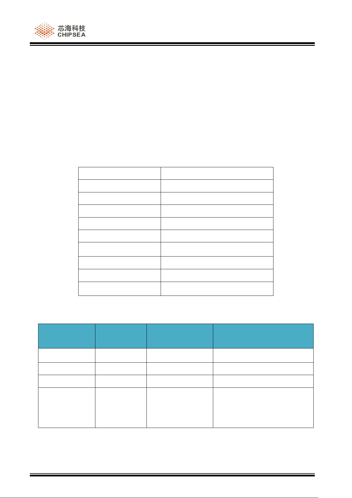
Master control chip
CSU8DL3510
Master slave mode
slave
Working band
2.40GHz~2.48GHz
Bluetooth standard
Bluetooth 4.0
Working voltage
2.0V~3.6V
Transmission distance
20 meter
Communication interface
UART、SPI
Transmit power
+7dBm~-8dBm
Size
20.7mm(L)*15.5mm(W)*0.8mm(H)
Working temperature
-40~85℃
Event
Average
current
duration
test condition
Sleep
0.8uA
——
——
Broadcast
125uA
1s
Broadcast period 500ms,20byte
connection
285uA
1s
Connecting period 100ms
Transmission
(Send to APP by
serial port)
1659uA
10s
20 byte,4/s
1 PRODUCT
1.1 Function description
CSM3510 Bluetooth module is adopted the core SOC CSU8DL3510 chip, supports Bluetooth
4.0 protocol, supports UART, SPI interface. The module can switch among different
mode ,including broadcast mode, transmission mode and sleep mode. CSM3510 is used for
Bluetooth slave mode block, working voltage is from 2.0V to 3.6V, transmit power is from +
8dBm to - 7dBm, broadcast, transmission mode for each frame data is 20 byte
1.2 Main characteristics
1.3 Power consumption
Note:Average current test method: Using the uA stall of multimeter to view the display data
between the battery and the module, the test voltage is 3.0V. The transmit power is set to 0dBm
Page 5
CSM3510
RREEVV33..33 PPaaggee 55,, 1166 ppaaggees
s
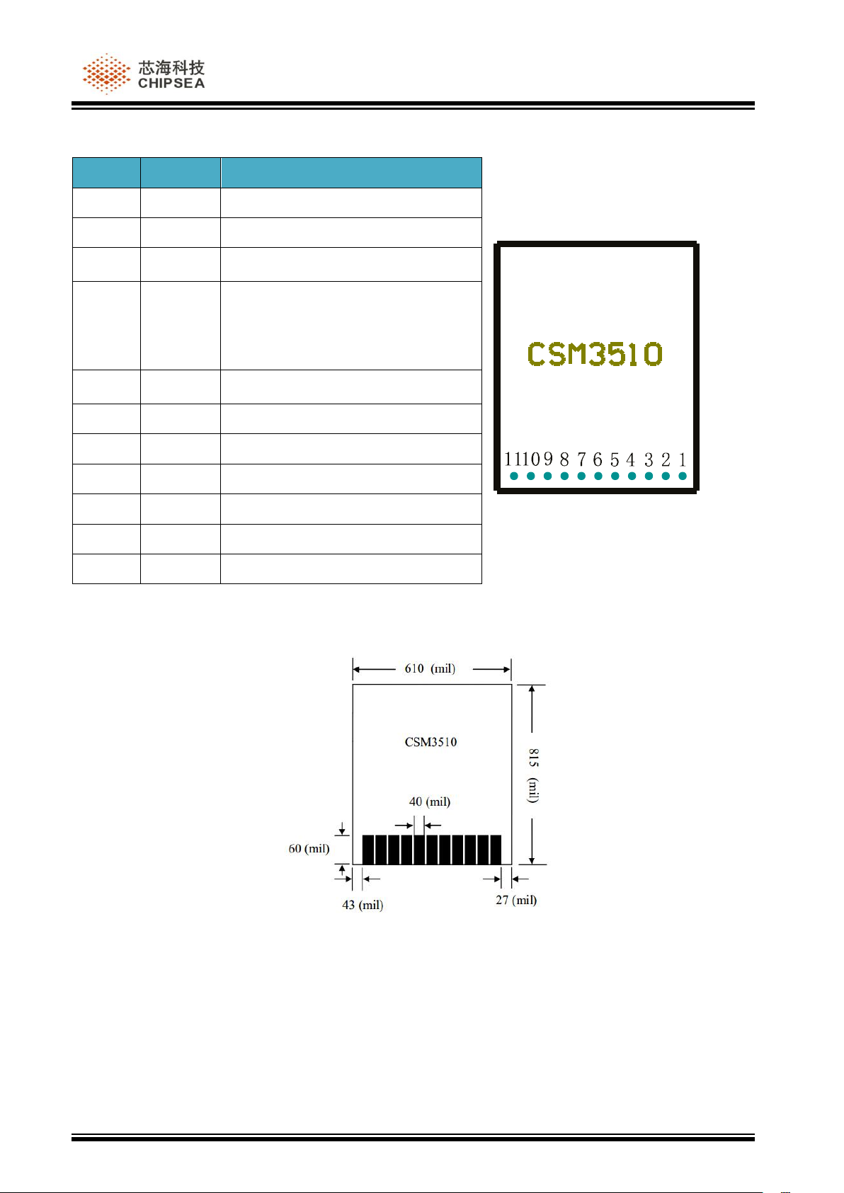
8 6 5 1234791011
NO.
pin
instruction
1
TX
UART pin for sending
2
RX
UART pin for receiving
3
P1.3
——
4
P0.7
Low level select SPI interface
High level or suspended select
UART interface
5
P0.4
——
6
SEEL
SPI slave chip
7
MISO
SPI host input pin
8
MOSI
SPI host output pin
9
SCLK
SPI clock output pin
10
3.3V
Power input
11
GND
Power source
1.4 Interface definition
1.5 Package size chart
Page 6
CSM3510
RREEVV33..33 PPaaggee 66,, 1166 ppaaggees
s
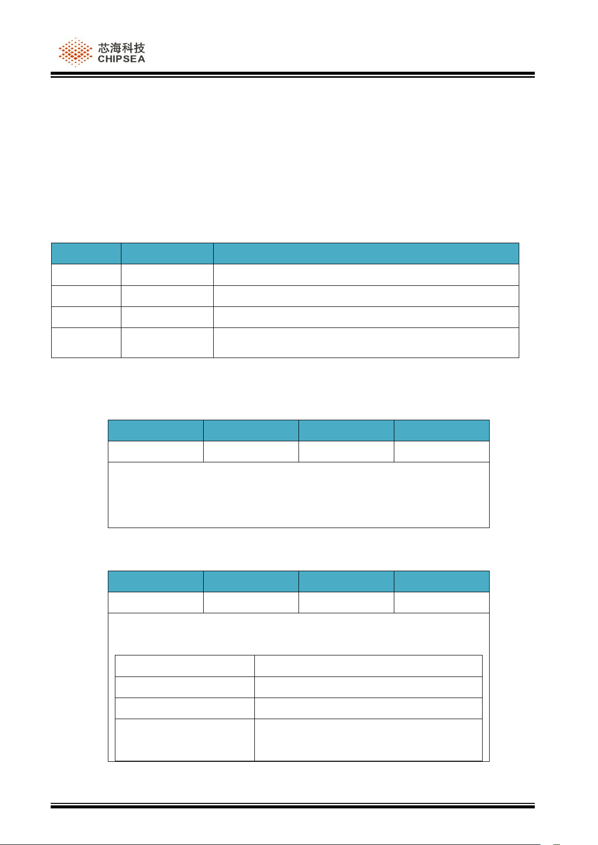
Byte
Value
Description
0~3
0x100000C5
Start byte, fixed to 0x100000C5
4
0x--
Data length, representing the number of data bytes
5~--
0x--
Data content
--
0x--
Check byte, check byte =0xC5 ⊕Data length⊕Data (⊕
representing XOR, the same below)
Start byte
Data length
Data
Check byte
0x100000C5
0x01
0x80
0x44
Function:Make Bluetooth module get into the sleep mode, the Bluetooth
module can be waked up by falling edge from the RX pin, also can be
waked up through the serial port to receive 0x100000.
Start byte
Data length
Data
Check byte
0x100000C5
0x01
0x81
0x45
Function: query the current state of the Bluetooth module, and return the
value as follows:
UART return
state
0x C5 01 01 C5
Bluetooth module in broadcast state
0x C5 01 02 C6
Bluetooth module in the connection process
0x C5 01 04 C0
The Bluetooth module is connected
successfully, it can transmit data
2 MODULE OPERATION
2.1 UART interface
2.1.1 Serial baud rate
9600bps,8 bit,No parity bit, 1 stop bit.
2.1.2 Packet format
2.1.3 Control instruction introductioin
(1) Sleep instruction
(2) Bluetooth module state query instruction
Page 7

CSM3510
RREEVV33..33 PPaaggee 77,, 1166 ppaaggees
s
Start byte
Data length
Data
Check byte
0x100000C5
0x03
0x82
ADV_Time
0x--
Function:Set up Bluetooth module broadcast period,Default 100ms
Connection period =1.25ms*ADV_Time
Data format is 2 byte:
Data[1]
Data[2]
For example: set the broadcast period to 1000ms, the instruction is as
follows:
ADV_Time=1000/1.25=0x320
Data[1]=250/1.25=0x03
Data[2]=0x20
Check byte =0xC5⊕0x03⊕0x82⊕0x03⊕0x20=0x67
0x100000C5
0x03
0x82
0x03
0x20
0x67
(3)Bluetooth module broadcast period setting instruction
Page 8

CSM3510
RREEVV33..33 PPaaggee 88,, 1166 ppaaggees
s
Start byte
Data length
Data
Check byte
0x100000C5
0x07
0x83
Update_Time
0x--
Function: set up the Bluetooth module connection period, the default is the
minimum interval (MinInterval) 50ms, the maximum connection interval
(MaxInterval) 100ms, the connection timeout (TimeOut) 6s.
Data format is six bytes:
MinInterval
MaxInterval
Timeout
Data[1]
Data[2]
Data[3]
Data[4]
Data[5]
Data[6]
BLE Connect Interval=Interval*1.25ms
BLE Connect Supervision Timeout =Timeout*10ms
For example: set MinInterval=500ms,MaxInterval=1000ms,
Timeout=3000ms.
Data[1]Data[2]=500/1.25=0x0190;
Data[3]Data[4]=1000/1.25=0x320;
Data[5]Data[6]=3000/10=0x012c;
Check byte =0xC5⊕0x07⊕0x83⊕0x01⊕0x90⊕0x03⊕0x20⊕0x01⊕
0x2c=0xde
0xc5
0x07
0x83
0x019003200012
0xde
Start byte
Data length
Data
Check byte
0x100000C5
0x--
0x84
Adv_data
0x--
Function: set up the Bluetooth module broadcast content
Adv_data data length≤20byte.
Check byte=0xC5⊕data length⊕data.
(4)Bluetooth module connection period setting instruction
(5)Broadcast content setting instruction
Page 9

CSM3510
RREEVV33..33 PPaaggee 99,, 1166 ppaaggees
s
Start byte
Data length
Data
Check byte
0x100000C5
0x01
0x85
0x41
Function:Set up the Bluetooth module for the connection state,it is default
to be in the connection state
Start byte
Data length
Data
Check byte
0x100000C5
0x01
0x86
0x42
Function:Set up the Bluetooth module for the non connection state,it is
default to be in the connection state. After setting ,the Bluetooth module
can be searched, the broadcast data can also be received, but can not be
connected
Start byte
Data length
Data
Check byte
0x100000C5
0x01
0x87
Value
0x--
Function: Set up the Bluetooth module transmit power, the default value is
Value=1.
Value
transmit power
1
7dBm
2
5dbm
3
4dbm
4
2dbm
5
0dbm
6
-4dbm
7
-8dbm
Start byte
Data length
Data
Check byte
(6)Set up the Bluetooth module for the connection state
(7)Set up the Bluetooth module for the non connection state
(8)Set up Tx Power
(9)Disconnect Bluetooth connection
Page 10

CSM3510
RREEVV33..33 PPaaggee 1100,, 1166 ppaaggees
s
0x100000C5
0x01
0x88
0x4C
Function: Disconnect the current Bluetooth connection from the connection
state to the broadcast state.
Start byte
Data length
Data
Check byte
0x100000C5
0x--
0x89
Name
0x--
Function:Modify Bluetooth name.
Note:Check byte=0xC5⊕data length⊕data
Start byte
Data length
Data
Check byte
0xC5
0x01
0x80
0x44
Function:Respond after instruction execute successfully.
Start byte
Data length
Data
Check byte
0xC5
0x01
0x81
0x45
Function:Respond after instruction fail.
Start byte
Data length
Data
Check byte
0xC5
0x01
0x82
0x46
Function: instruction check byte error.
Start byte
Data length
Data
Check byte
0xC5
0x01
0x--
0x--
Function: when the Bluetooth module receives the instruction of the query
module state, return the current state response instruction.
data
State
0x01
Bluetooth module in broadcast state
0x02
Bluetooth module in the connection process
(10)Modify Bluetooth name
2.1.4 Response instruction
(1)Execute success response instruction
(2)Execute failure response instruction
(3)Execute failure response instruction
(4)Bluetooth module response instruction state
Page 11

CSM3510
RREEVV33..33 PPaaggee 1111,, 1166 ppaaggees
s
0x04
The Bluetooth module is connected successfully, and
it can transmit data
Start byte
Data length
Data
Check byte
0x100000C5
0x--
0x94
DATA
0x--
Function: send DATA data to APP. Below to send "0x010203" as an
example
Start byte
Data length
data
Check byte
0x100000C5
0x04
0x94010203
0x55
Note:Check byte=0xC5⊕data length⊕data
2.1.5 Send data introduction
Page 12

CSM3510
RREEVV33..33 PPaaggee 1122,, 1166 ppaaggees
s
Broadcast
data packet
Set broadcast data packet
Instruction completion
Read broadcast channel
Instruction completion
Set broadcast parameter
CSM3510
Link layer
Instruction completion
Set scan response data
Instruction completion
Begin broadcast
Instruction completion
Shut down broadcast
Instruction completion
3 WORK STATE CHART
3.1 Broadcast state chart
CSM3510 can set the broadcast interval, broadcast content, and broadcast type etc by instruction
setting. After setting,the CSM3510 will enter broadcast mode. The CSM3510 can also shut down
the broadcast by instruction or enter the sleep mode. Refer to the 2.1.3 section for details.
Page 13

CSM3510
RREEVV33..33 PPaaggee 1133,, 1166 ppaaggees
s
Data Message
Connection request
Broadcast instruction
CSM3510
Phone
Slave
device
primary
device
Data Message
MCU
APP
3.2 Connection state chart
CSM3510 is in a broadcast state , other Bluetooth devices around can initiate a connection
request. After connecting and entering the Transmission mode, it can begin the data
transmission.CSM3510 will upload the data received by UART or SPI interface to the app, also can
send the data downloaded from app to the mcu by UART or SPI interface. As shown in 2.1.5.
Page 14

CSM3510
RREEVV33..33 PPaaggee 1144,, 1166 ppaaggees
s
4 BLUETOOTH MODULE DEBUGGING
4.1 computer serial assistant debugging
(1) The Bluetooth module is connected to the 3.3V power supply via the 3.3V pin and the GND
pin.
(2) TX and RX pins are connected to a computer via a MAX232 Level conversion.
(3) Open the phone APP, click on the search button in right corner , you can search the
Chipsea-BLE Bluetooth module, as shown in Figure 3.1.1. Click Chipsea-BLE, enter the
connection interface, as shown in Figure 3.1.2.
figure3.1.1 figure3.1.2
Page 15

CSM3510
RREEVV33..33 PPaaggee 1155,, 1166 ppaaggees
s
(4) Open the computer serial assistant, query the current status of the Bluetooth module
instruction, as shown in Figure 3.1.3, you can see the Bluetooth module return the current state
of the instruction, as shown in figure 3.1.4.
figure3.1.3 figure3.1.4
Page 16

CSM3510
RREEVV33..33 PPaaggee 1166,, 1166 ppaaggees
s
5 USE NOTES
(1) CSM3510 passthrough one frame whose data up to 20 bytes, it will not be sent out if you
exceed the 20 bytes , so make sure that a frame of data no exceed 20 bytes.
(2) CSM3510 connection interval is 100ms by default, maximum frequency is 10 packets per
second.
(3) CSM3510 parameter will return to the default value when power outage.
(4) After CSM3510 enter sleep mode,the Bluetooth module can be waked up by falling edge
from the RX pin, Bluetooth module will be reset after the wake, it costs 30ms.
Page 17

The output power of this device is less than 20mW.The SAR test is not required.
This device complies with Part 15 of the FCC Rules. Operation is subject to the following
two conditions: (1) This device may not cause harmful interference, and (2) this device must
accept any interference received, including interference that may cause undesired operation.
NOTE: The manufacturer is not responsible for any radio or TV interference caused by
unauthorized modifications or changes to this equipment. Such modifications or changes
could void the user’s authority to operate the equipment.
A certified modular has the option to use a permanently affixed label, or an electronic label.
For a permanently affixed label, the module must be labelled with an FCC ID:
2AGM5CSM3510. The OEM manual must provide clear instructions explaining to the
OEM the labelling requirements, options and OEM user manual instructions that are
required
For a host using a this FCC certified modular with a standard fixed label, if (1) the module’s
FCC ID is not visible when installed in the host, or (2) if the host is marketed so that end
users do not have straightforward commonly used methods for access to remove the module
so that the FCC ID of the module is visible; then an additional permanent label referring to
the enclosed module:
“Contains Transmitter Module FCC ID: 2AGM5CSM3510 or “Contains FCC ID:
2AGM5CSM3510” must be used. The host OEM user manual must also contain clear
instructions on how end users can find and/or access the module and the FCC ID.
Host product is required to comply with all applicable FCC equipment authorizations
regulations, requirements and equipment functions not associated with the transmitter
module portion. compliance must be demonstrated to regulations for other transmitter
components within the host product; to requirements for unintentional radiators (Part 15B).
To ensure compliance with all non-transmitter functions the host manufacturer is
responsible for ensuring compliance with the module(s) installed and fully operational. If a
host was previously authorized as an unintentional radiator under the Declaration of
Conformity procedure without a transmitter certified module and a module is added, the
host manufacturer is responsible for ensuring that the after the module is installed and
operational the host continues to be compliant with the Part 15B unintentional radiator
requirements. Since this may depend on the details of how the module is integrated with
the host, we suggest the host device to recertify part 15B to ensure complete compliance with
FCC requirement: Part 2 Subpart J Equipment Authorization Procedures , KDB784748 D01
v07, and KDB 997198 about importation of radio frequency devices into the United States.
 Loading...