

Chip PC CDC01927 User Manual
Jack PC
EFI Series
Hardware User Manual
Revision C
06/06/2006
*CDC01927*
1

Jack PC Hardware User Manual - Training Department
Revision C 0506
COPYRIGHT NOTICE
© 2006 Chip PC Inc., Chip PC (Israel) Ltd., Chip PC (UK) Ltd. All rights reserved.
This manual and the software and hardware described herein, in whole or in part, may not be
reproduced, translated, or reduced to any machine-readable form without prior written approval.
CHIP PC SHALL NOT BE LIABLE FOR TECHNICAL OR EDITORIAL ERRORS OR OMISSIONS
CONTAINED HEREIN; NOR FOR INCIDENTAL OR CONSEQUENTIAL DAMAGES
RESULTING FROM THE FURNISHING, PERFORMANCE, OR USE OF THIS MATERIAL.
The information contained in this document represents the current view of Chip PC on the issues
discussed as of the date of publication. Because Chip PC must respond to changing market
conditions, it should not be interpreted to be a commitment on the part of Chip PC, and Chip PC
cannot guarantee the accuracy of any information presented after the date of publication.
This Guide is for informational purposes only. CHIP PC MAKES NO WARRANTIES, EXPRESS
OR IMPLIED, IN THIS DOCUMENT.
U.S. GOVERNMENT RESTRICTED RIGHTS
The Software and documentation are provided with RESTRICTED RIGHTS. Use, duplication, or
disclosure by the Government is subject to restrictions as set forth in subparagraph (c)(1)(ii) of
the Rights in Technical Data and Computer Software clause at DFARS 252.227-7013 or
subparagraphs (c)(1) and (2) of the Commercial Computer Software—Restricted Rights at 48
CFR 52.227- 19, as applicable. MANUFACTURER is Chip PC Inc.
PATENTS
The product(s) described herein are protected by multiple international patents.
TRADEMARKS
Xcalibur, Xtreme PC, Jack PC, Chip PC and the Chip PC logo are either trademarks or registered
trademarks of Chip PC.
Products mentioned in this document may be registered trademarks or trademarks of their
respective owners
The Energy Star emblem does not represent endorsement of any product or service.
Registration Note: The unit is covered with Chip PC Limited Warranty for one year; Additional 2
years are pending on product registration at Chip PC website: www.chippc.com/support
The information and specifications in this document are subject to change without notice.
2

Jack PC Hardware User Manual - Training Department
Revision C 0506
TABLE OF CONTENT
1 SAFETY NOTICES............................................................................................................................................................4
1.1 Safety Instructions...............................................................................................................5
2 INTRODUCTION................................................................................................................................................................6
2.1 Power Options.....................................................................................................................8
2.2 Intended Audience..............................................................................................................9
2.3 Main Topics Overview.........................................................................................................9
2.4 More Information.................................................................................................................9
3 HARDWARE SETUP 10
3.1 Site Preparation ................................................................................................................10
3.2 Package Contents.............................................................................................................10
3.3 Identifying the Parts of the Jack-PC ...........................................................................11
3.4 Existing LAN Installation .............................................................................................12
3.5 New Installation ..........................................................................................................16
3.6 Connecting the Cables ...............................................................................................21
3.7 Turning the Jack-PC ON .............................................................................................22
3.8 Unplugging the System When Using External Power.......................................................22
3.9 Reseting the Jack-PC .......................................................................................................22
4 JACK-PC MODELS ...................................................................................................................................................23
5 JACK-PC SPECIFICATIONS ....................................................................................................................................24
6 WIRING CONFIGURATIONS ...................................................................................................................................26
6.1 LAN wiring basics..............................................................................................................26
6.2 LAN wiring color coding ..............................................................................................27
6.3 Non-standard LAN cabling .........................................................................................28
6.4 Testing LAN Cabling ...................................................................................................29
6.5 Switch Settings..................................................................................................................29
6.6 PoE Settings .....................................................................................................................29
6.7 Pre-standard PoE .......................................................................................................31
7 TROUBLESHOOTING ................................................................................................ ..............................................32
7.1 Basic Troubleshooting flow...............................................................................................32
7.2 Reseting the Jack-PC to Factory Default Settings (RFD) ..........................................33
7.3 LAN Troubleshooting flow ...........................................................................................36
7.4 PoE Troubleshooting flow ...........................................................................................38
8 ACCESSORIES LIST ................................................................................................................................................39
9 REGULATORY COMPLIANCE .................................................................................................................................44
9.1 Jack-PC Requirements Compliance.................................................................................44
9.2 FCC Statements................................................................................................................44
9.3 IEC/EN Notice...................................................................................................................44
9.4 Modifications .....................................................................................................................44
9.5 Cables...............................................................................................................................44
9.6 Peripheral Devices............................................................................................................44
10 CHIP PC LIMITED HARDWARE WARRANTY ........................................................................................................49
11 CHIP PC LIMITED SOFTWARE WARRANTY .........................................................................................................52
12 CHIP PC SOFTWARE LICENSE AGREEMENT .....................................................................................................54
13 MICROSOFT END USER LICENSE AGREEMENT (EULA) ...................................................................................56
3
Jack PC Hardware User Manual - Training Department
Revision C 0506
Welcome and congratulations on your purchase of the Jack PC!
This User Manual contains the information you will need in order to set up your Jack PC's
hardware.
For information concerning the Jack-PC's software aspects, please refer to the Software User
Manuals, that can be found at www.chippc.com
1 SAFETY NOTICES
This section contains important safety notices. Please read carefully as improper handling of the
product may result in serious personal injury and/or termination of warranty!
Caution: Never open the product’s enclosure and never attempt to replace or fix any internal
part! Any attempt to repair the product, install or replace components by an unauthorized person
could expose that person to risk electrical shock and will cause the product warranty to be void.
Only trained and qualified personnel should be allowed to install, replace, or service
this equipment. For any problem, please contact the nearest authorized service provider.
Caution: To prevent possible electrical shock when installing the product, do the following:
Make sure that the connected display is properly grounded through the mains plug.
Any peripheral device connect to the Jack-PC, must be connected to properly wired receptacles.
Caution: when using an external power supply (5VDC AC/DC adapter) use only Chip PCsupplied, UL-listed direct plug in AC/DC adapter, (Chip PC part number: CPN1491 or CPN1503
or CPN1504). Using a different power supply might expose the user to various risks, damage the
device and will void the product's warranty!
Caution: When using USB devices that power from the Jack-PC's UBS ports, be aware that
heavy electrical loads on the USB ports can cause instable operation and excessive heat buildup;
therefore it is better to use the USB device's external power supply.
Caution: This product is designed for indoor use only!
Important Note: When preparing a new installation, note the following cautions:
• Do not drill next to electricity/telephone lines.
• Test for existence of power lines or enforcement beams prior to drilling the wall
cutout.
• Make sure to comply with any building standards that might exist in the
building that the Jack PC is designated to be installed.
Important Note: The product is to be installed in compliance with the requirements of
the Canadian electrical Code (CEC) and the National Electrical Code in USA.
4

When using an external power supply, place the DC power cord in such a way to
f
time, it is better to turn off the device by removing the power supply from the mains
The product should be stored and used only in temperature and humidity controlled
(Chip PC part number: CPN1491 or
Using a different power supply might expose the user to
The product is to be installed in compliance with the requirements of the Canadian
Jack PC Hardware User Manual - Training Department
Revision C 0506
1.1 Safety Instructions
Please read the following safety instructions carefully before using the product:
• Be sure not to expose the product to excessive humidity.
•
If one of the following situations occurs, be sure to get the product checked by a qualified service
technician:
.
avoid people stepping on it.
• When using an external power supply, if the product is not used for a long period o
socket.
•
environments as defined in the product environmental specifications.
• When using an external power supply (5VDC AC/DC adapter) use only Chip PC-
supplied, UL-listed direct plug in AC/DC adapter
CPN1503 or CPN1504).
various risks, damage the device and will void the product's warranty!
•
electrical Code (CEC) and the National Electrical Code in USA.
• The product’s power supply is overheated, damaged, broken, causes smoke
or shortens the mains power socket.
• Liquid penetrates the product case.
• The product is exposed to excessive moisture or water.
• The product has been mechanically damaged.
• The product has obvious signs of breakage or internal loose parts.
• In EU: Installation done not in accordance with EU required standards
• In US: Installation done not in accordance with US required standards
5
Jack PC Hardware User Manual - Training Department
Revision C 0506
2 INTRODUCTION
The Jack PC is a versatile, feature-rich thin client computer fully integrated into an existing LAN
Jack, it is the most secure, modular, and manageable Thin-Client solution offering connection to
any type of popular Terminal, Citrix or Legacy servers.
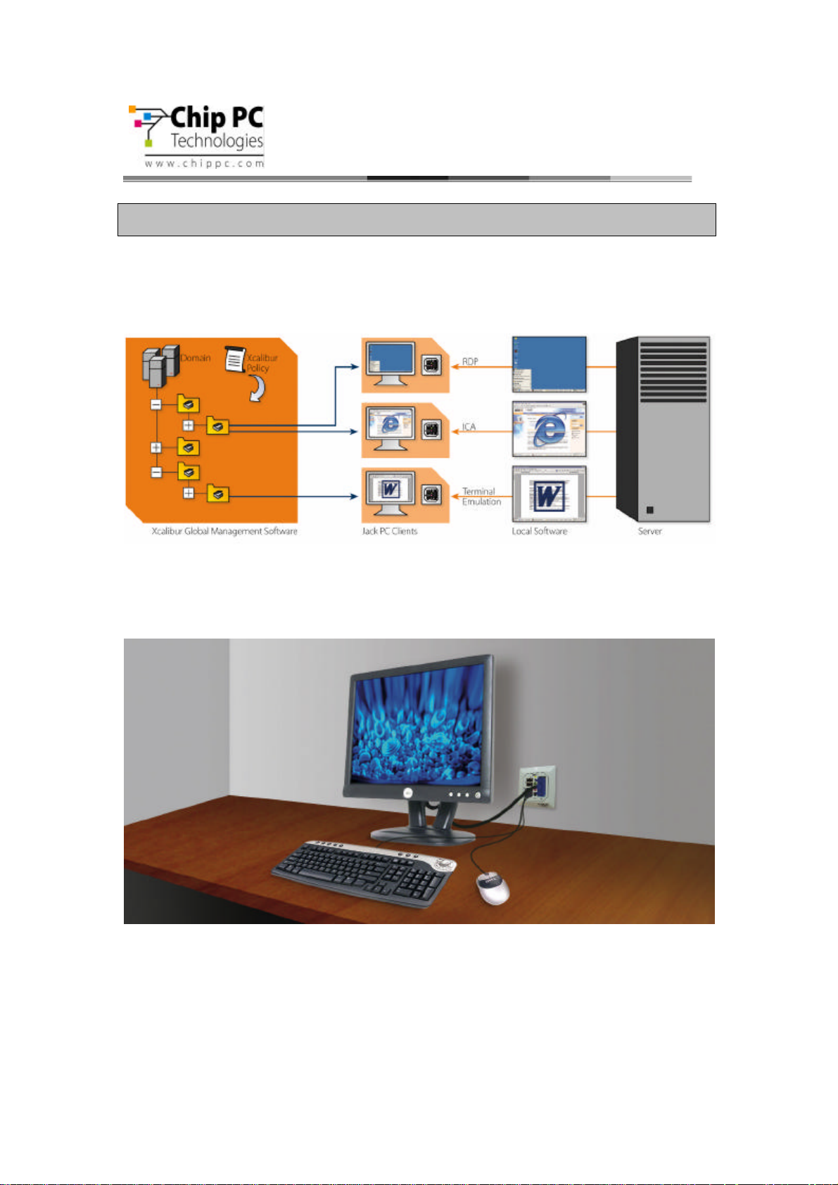
With the Jack PC, you can quickly and easily convert an existing enterprise LAN jack into a fullyworking, remotely-managed computer without installing additional cabling. The Jack PC is
connected at the back side through Ethernet cable to the building's LAN. The front panel is
connected (through cables or wirelessly) to the display, keyboard, mouse and other peripherals.
For extended functionality, Jack PC supports a wide set of accessories, such as External USB
PC/SC Smart Card Reader, various adapters such as USB-to-PS/2, USB-to-Serial and more. See
Accessories list for more details.
6
Jack PC Hardware User Manual - Training Department
Revision C 0506
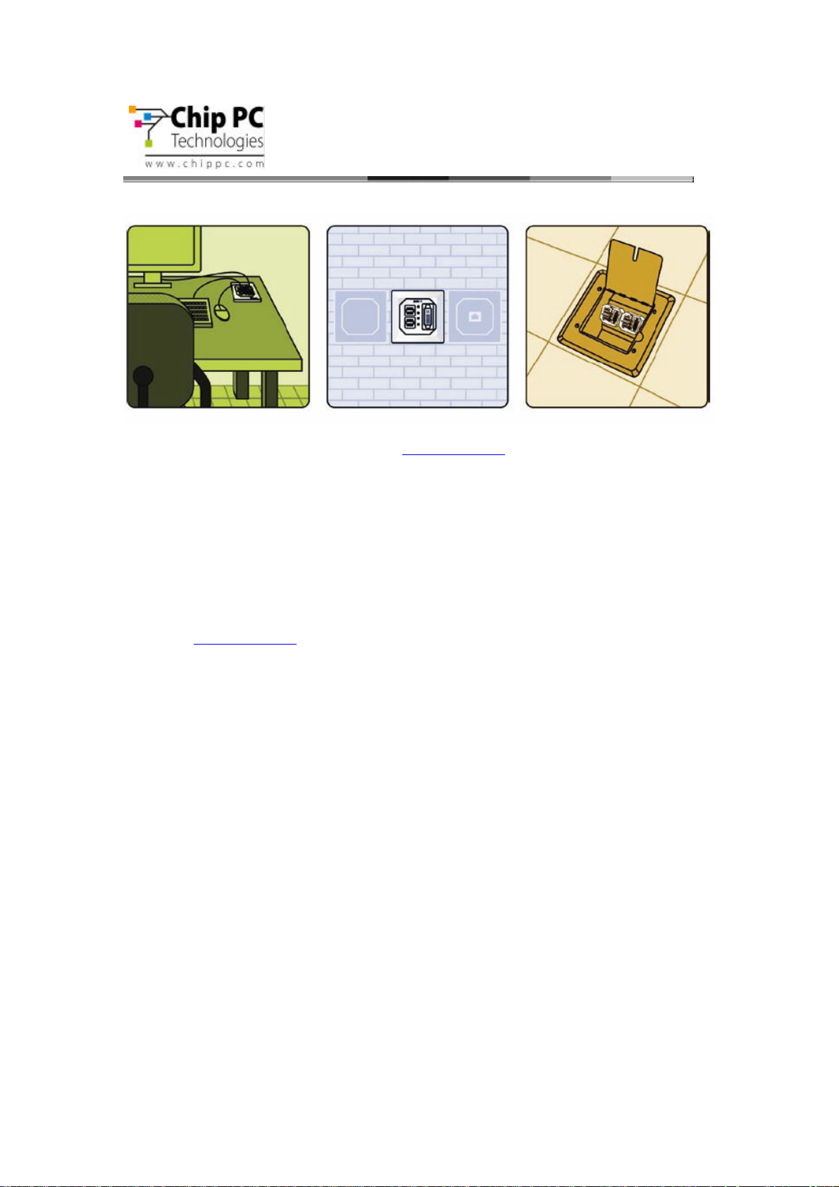
The Jack PC can be fitted into wall, floor or furniture housing according to site specific needs.
Installation is easy and quick and enables an organization-wide usage of LAN Jacks for various
uses offered by the Flex-Jack system (see www.chippc.com for more details about additional
Flex-Jack devices).
The Jack PC is secured inside the wall and behind the faceplate, eliminating exposure to
damage, disconnection or theft. Highest security is also featured in the Jack PC local image
software with its unique modular operating system and Digital Signature layer, which provide a
virus-immune to the highest security standard.
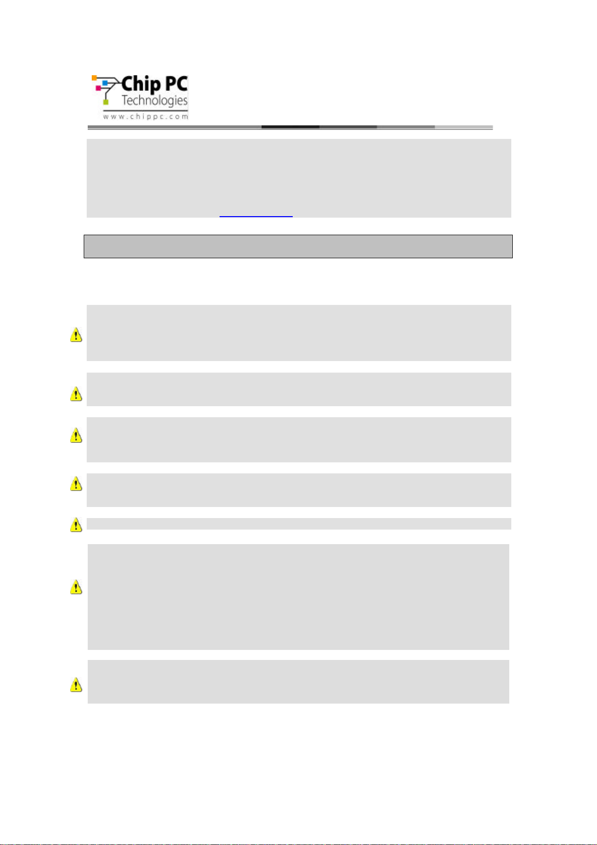
Jack PC deployment and on-going maintenance are fully automated by using Xcalibur Global
Management software, offering a real plug-and-play solution - Just connect the Client to your
network and the rest will happen automatically. Configuration is quick and painless, management
is fast and effective, and installation couldn't be easier. For more information about Xcalibur
Global see www.chippc.com)
With its great performance, high security, easy deployment and management, the Jack PC is the
thin-client-of-choice for enterprises and organizations all over the world.
The Jack PC unfolds important advantages to enterprise IT and network managers, and to
decision makers:
• Minimize installation space and wiring - Just connect the display, keyboard and
mouse
• Get highest physical security computer - Locks into the housing, no exposed/
removable components.
• Get the world first computer powered by standard PoE (PoE IEEE 802.3af) port.
Just like IP telephony! No need for power supply and wiring.
• Save on lowest heat and power consumption - only 5W!
• Enjoy the most flexible and highest performance thin client in the market today -
Resident Citrix ICA, Microsoft RDP, local browser IE 6 and other plug-ins for local
applications.
• Benefit from the best remote management software - with Xcalibur Global. Location
memory feature for accurate location pinpointing. 100% remote configuration - now as
part of your Active Directory – managed with policies just like PCs.
• Part of Flex Jack system - where a variety of compatible modules can be inserted into
the same infrastructure housings (see accessories list).
• Patented - protected by multiple International Patents.
• Certified - to meet Global Certification to the highest standards.
7
Jack PC Hardware User Manual - Training Department
Revision C 0506
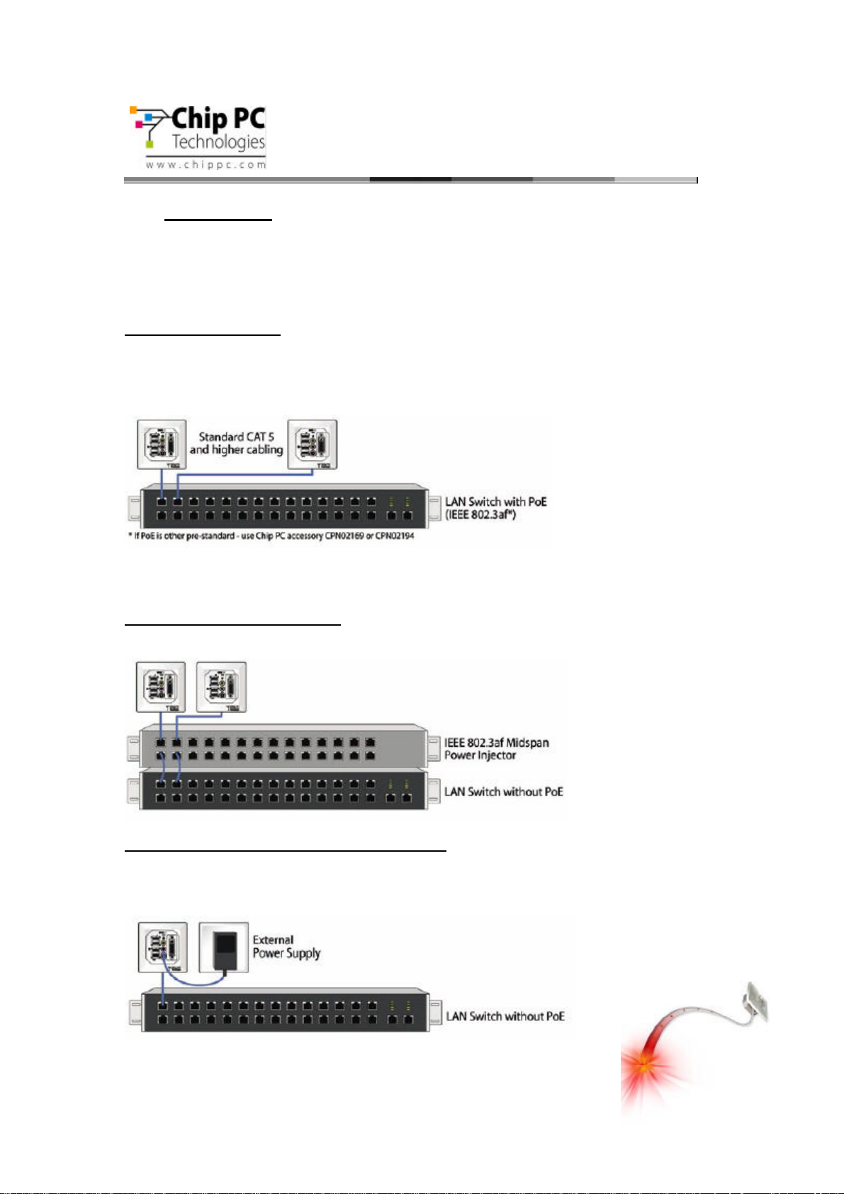
2.1 Power Options
Power-over-Ethernet (PoE) becomes a common technology as many sites adding PoE to
support VOIP telephony and wireless access points. Jack PC devices are especially built to be
powered by Power-over-Ethernet infrastructure. However, where there is no PoE switch
available, Jack PCs can be powered through a Midspan injector or with the external power supply
supplied by Chip PC.
1) PoE Switch Available
The Jack PC thin clients are connected at the back side through Ethernet cables to the building
LAN and receive Power-over-Ethernet through the existing CAT-5 enterprise infrastructure. Jack
PC, is the world’s lowest power desktop, consumes only 5W at full work mode, which means
significant costs-savings to the enterprise.
The Jack PC supports the industry PoE standard 802.3AF. Check that your switch has 802.3AF
support, if you are not sure – check with your Switch provider, see section 6.6 for more
information.
2) Switch + Midspan PoE Injector
If Power-over-Ethernet is not available, Midspan power injectors can be added to complement
existing LAN switches and create PoE infrastructure for all/specific ports.
3) Standard LAN Switch + External Power Supply
Another option is to use Jack PC devices with external DC power jack enabling standard wall
mounted power supply connection. Jack PC devices should only be used with Chip PCsupplied power supplies (Chip PC part number: CPN1491 or CPN1503 or CPN1504).
8

Jack PC Hardware User Manual - Training Department
Revision C 0506
2.2 Intended Audience
This User Manual is primarily intended for IT staff and administrators, though end-users and
others might find it helpful as well.
2.3 Main Topics Overview
This User Manual covers the hardware aspects of your new Jack PC, including hardware setup
and installation, wiring and network configuration, troubleshooting etc.
Our complementary Software User Manual covers the software aspects such as: software setup
and device settings (network definitions, display, keyboard and mouse properties, connections to
server(s) and more).
2.4 More Information
Questions about the Jack PC should be directed to Chip PC support; to an authorized Chip PC
service provider; or the Technical Support Department of the distributor from which you
purchased your Jack PC. Please have all pertinent information available when requesting help,
including any error messages that may have appeared either on the Jack PC or on the server. In
case you are unable to solve your problem you can contact Chip PC’s technical support through
https://www.chippc.com/support/
If you have any corrections / remarks on this user manual, please email them directly to:
jack-pc_pm@chippc.com
9
Jack PC Hardware User Manual - Training Department
Version 0506
3 HARDWARE SETUP
3.1 Site Preparation
Before installing the Jack PC make sure that:
• The site wiring is appropriate (power and network).
• The site is away from devices that can generate electrical noise,
electromagnetic interference, heat, vibration and such.
• The environmental requirements of the Jack PC as defined in the product
specifications are met.
• Caution: This product is designed for indoor use only!
• Warning: If you are not familiar with LAN wiring practice, use RJ-45
Termination Connector Block to avoid wiring (Part number CPN02164 or
CPN02166 - see accessories list). This connector can only be used to
connect the Jack PC to an existing LAN jack.
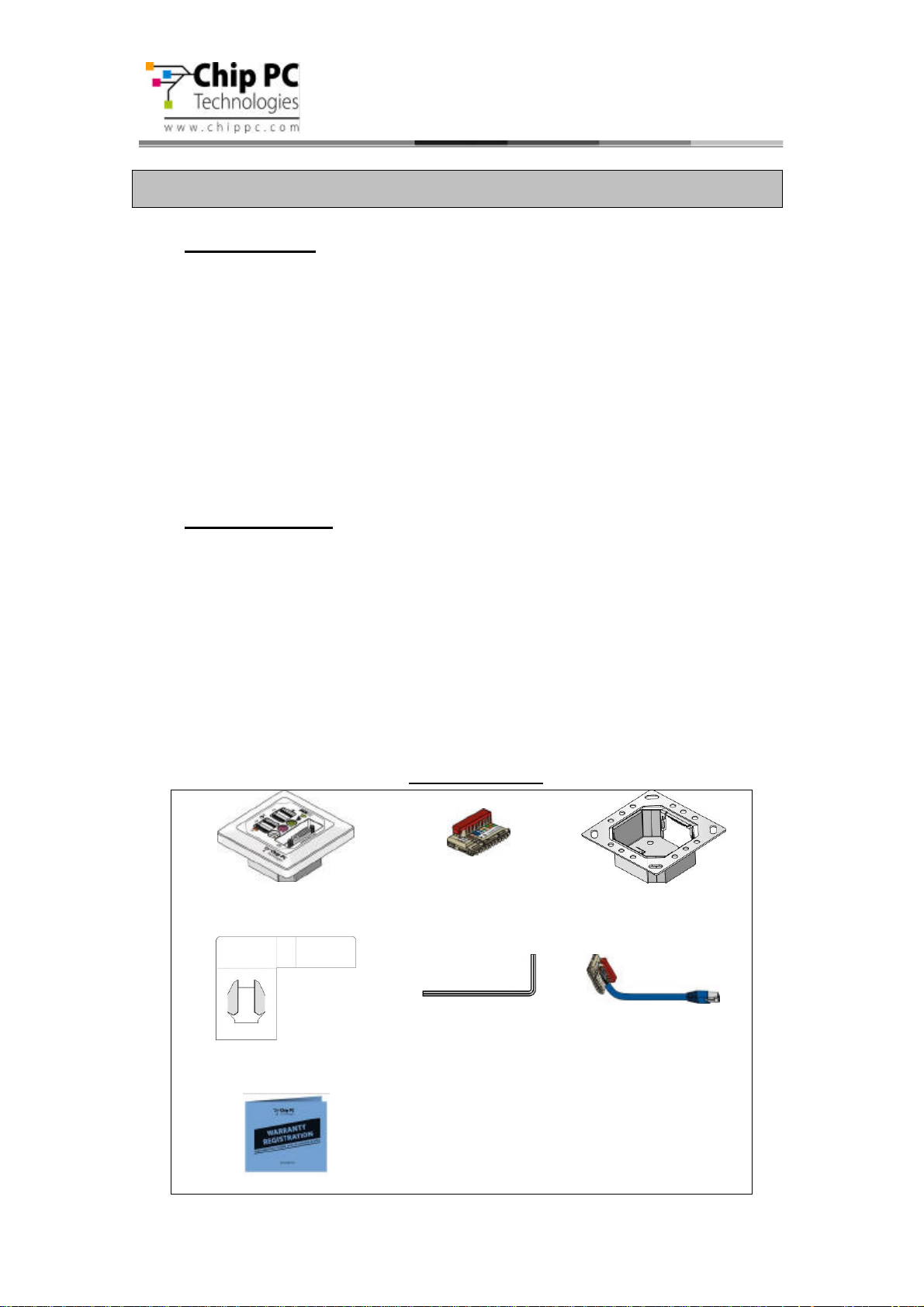
3.2 Package Contents
Unpack and identify the following parts:
1. Jack PC device (model EFI6700 or EFI680 or EFI6900).
2. IDC Termination Connector Block
3. Flex-Jack Metal Housing
4. Lower Cardboard Template that can be used for marking wall cutout in New
Installation
5. Extraction Tool to remove device after it was installed
6. RJ-45 Termination Connector Block (optional) (Note: This part must be ordered
separately in case you want to install the Jack PC in to an existing LAN jack. Chip PC
part number: CPN02164 or CPN02166 – see accessories list)
7. Warranty Registration Card
Package Contents
1. Jack PC device (Model
EFI6700 or EFI6800 or
2. IDC Termination
Connector Block
3. Flex-Jack Metal
Housing
EFI6900)
4. Lower Cardboard Template 5. Extraction Tool 6. RJ-45 Termination
Connector Block
(optional)
7. Warranty Registration Card
10
Jack
-
PC
Parts & I/O Ports
Screen
(optional)
Jack PC Hardware User Manual - Training Department
Version 0506
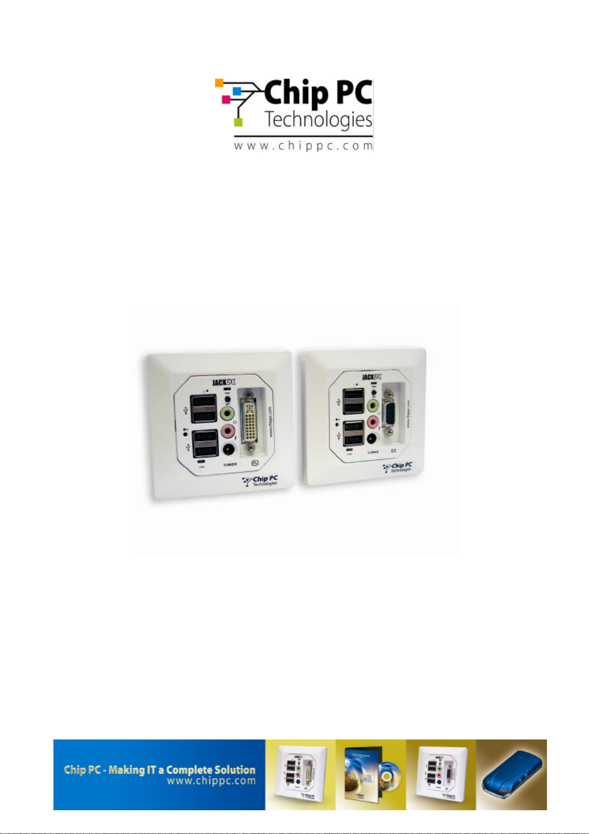
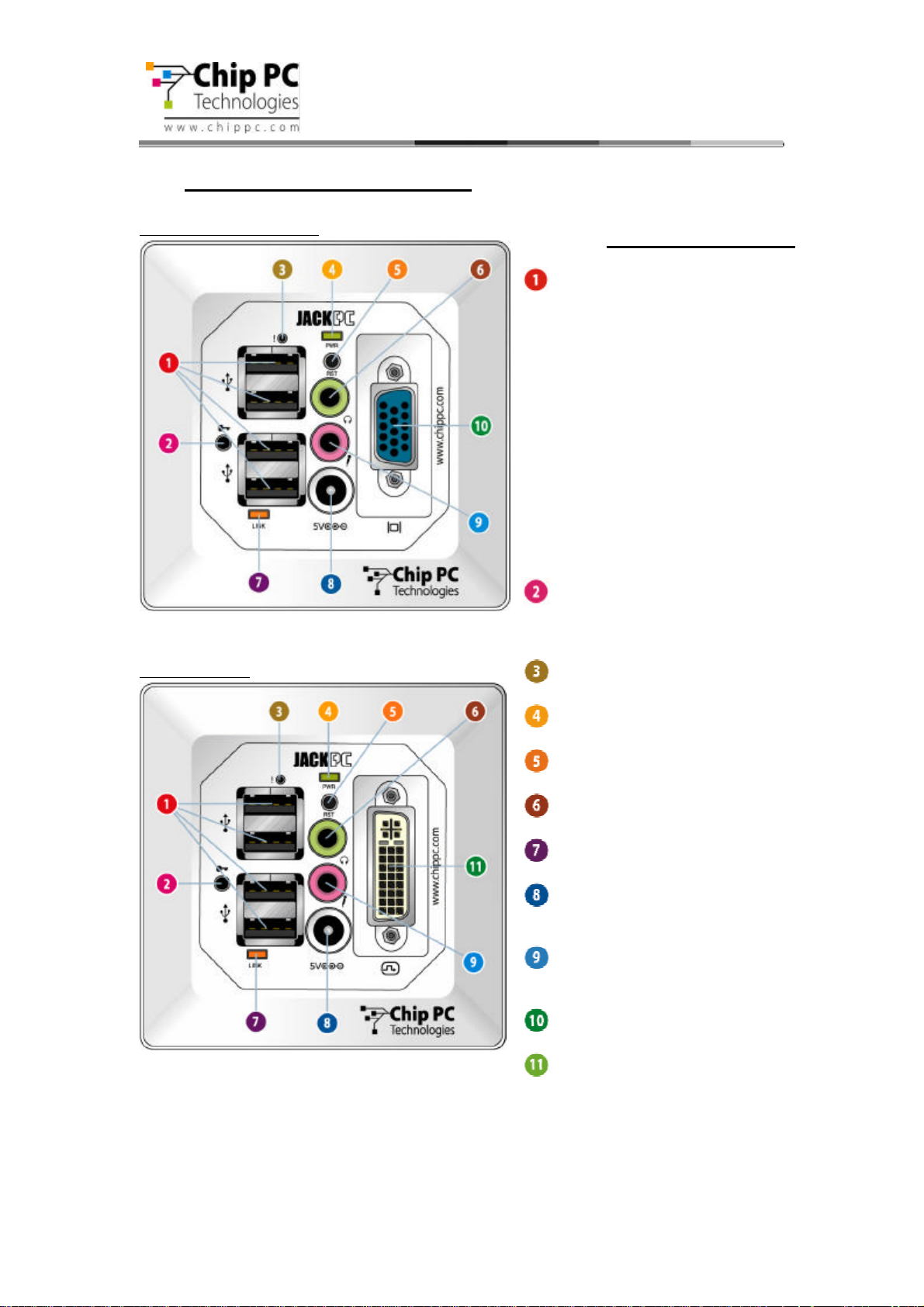
3.3 Identifying the Parts of the Jack-PC
Model EFI-6700 and 6800
Model EFI-6900
4 USB 2.0-compatible ports that can be
used for:
Extraction Point – insert Extraction tool
(latch) and turn it clockwise to remove
installed device
“Reset-to-Factory-Default” (RFD) Push
Button.
“Power/Fail” LED
“Reset” Button
Audio-Out 3.5 mm Jack for standard
speakers, headset or multimedia systems
“LAN Link & Activity” LED
DC Power Jack for wall-mounted power
supply, where no PoE available - the
device may be powered externally
Audio-In 3.5 mm Jack for standard
computer microphone
Analog Monitor Port
DVI-I Monitor Port. Supports Dual-
• Standard USB keyboard* including most
wireless models
• Standard USB mouse* including most
wireless models
• USB printers*
• External USB PC/SC Smart Card
Reader
• External mass-storage devices, such as
USB Flash Key, CD, Floppy, DVD,
Camera etc.
* In case a USB-to-PS/2 converter or USB-
to single/dual Serial ports adapter (to
support serial printers) is needed,
purchase it only from Chip PC to insure
compatibility. (See Accessories list)
11
Jack PC Hardware User Manual - Training Department
Version 0506
3.4 Existing LAN Installation
Tools you will need for Existing Jack Installation:
• Power-over-Ethernet Tester (where PoE is available (see power options 1 and 2 in
the introduction chapter) – it is recommended to verify that the LAN jack receives
power with this tester) - this is an optional accessory that you need to purchase
separately (Chip PC part number: CPN02239 – see accessories list).
• Screwdriver / Powered-screwdriver
• RJ-45 Termination Connector Block (this is an optional accessory that you need
to purchase separately)
• Half-round File to trim wall cutout
• Cloth to clean Housing contacts
• Extraction Tool to remove device after it was installed
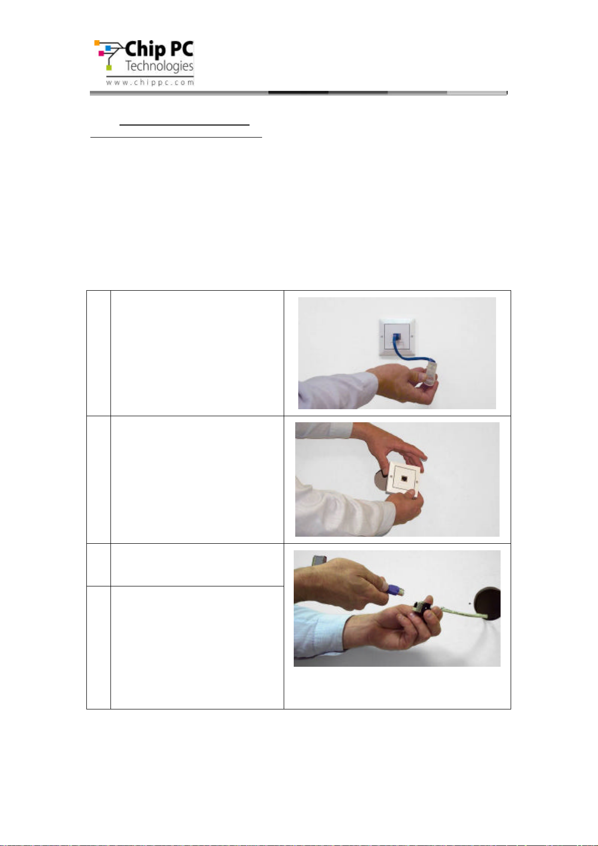
1 Use Power-over-Ethernet tester
(Chip PC part number: CPN02239)
to check existence of PoE in the
Jack designated for installation.
Note: In case there is no PoE
available, Jack PC can be powered
by External power supply (see step
13).
2 Remove the existing LAN Jack from
the wall.
Separate the LAN Jack module from
the front panel.
3 Pull out the LAN cable, holding the
RJ-45 Termination Connector Block,
4 Connect the LAN jack and RJ-45
connector on the RJ-45 Termination
Connector Block (this is an optional
accessory that you need to purchase
separately, in case you did not order
this part – go to New installation
paragraph (3.5), and continue the
instructions in the table from step 3).
12
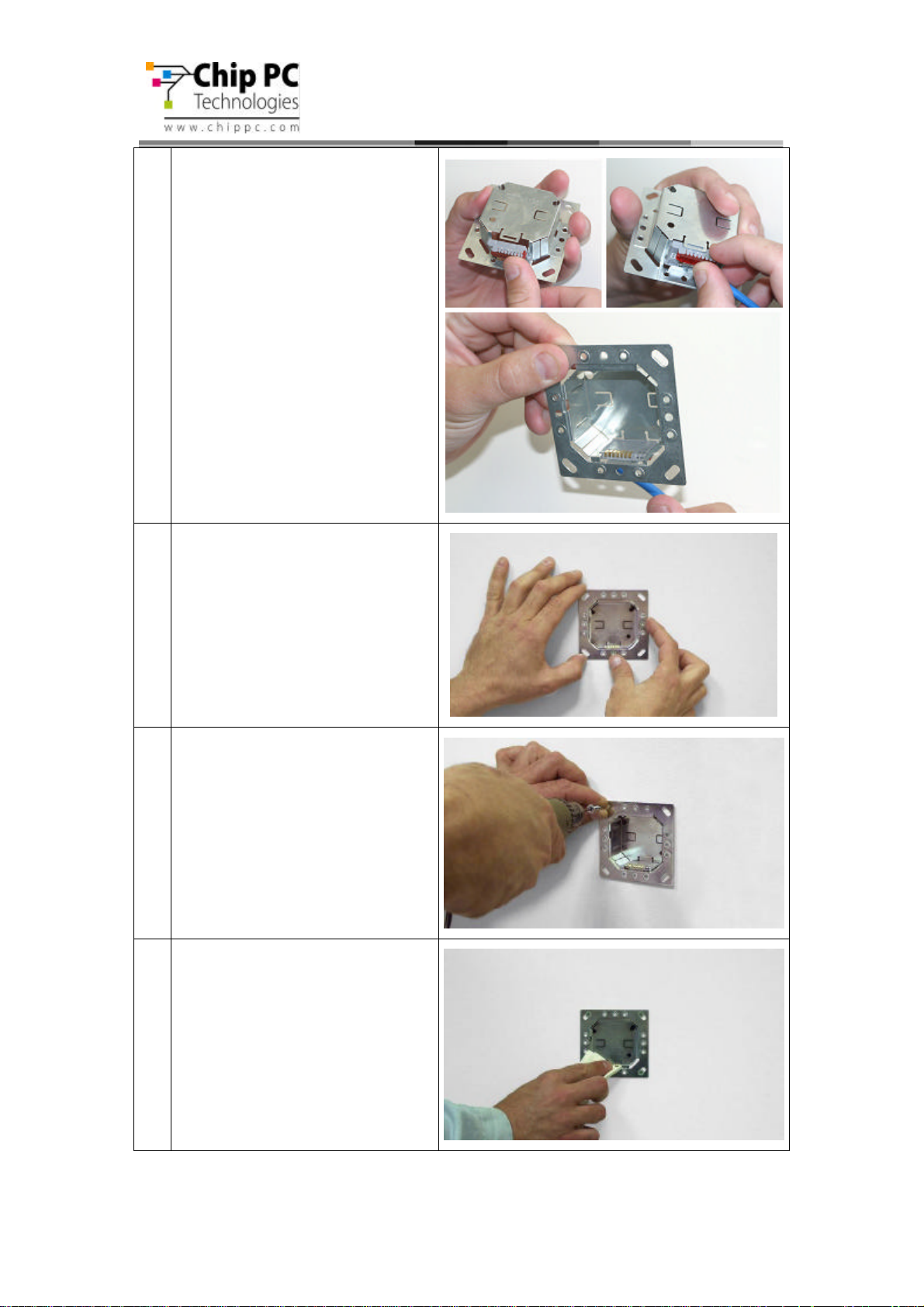
5 Insert the RJ-45 Termination
Connector Block into the Flex-Jack
Housing bottom part until you hear a
clicking sound indicating it has
locked properly into place.
Jack PC Hardware User Manual - Training Department
Version 0506
6 Place the Flex-Jack Housing inside
the Jack hole. Trim wall cutout if
necessary.
7 Test the Flex-Jack has current
before you continue.
Make sure that the Flex-Jack
Housing is fully inserted, levelheaded and that the Housing
contacts are located at the bottom
part as shown in picture.
Secure with 4 screws.
8 Gently clean the Flex-Jack Housing
contacts from dust, debris and other
objects.
13
Jack PC Hardware User Manual - Training Department
Version 0506
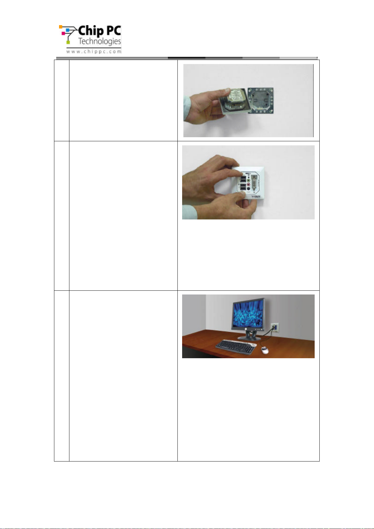
9 The Jack PC device should be
inserted with the contacts (shown in
the picture) facing downwards, as
shown in the picture.
10 Insert the Jack PC device into the
Housing until you hear a clicking
sound indicating the device has
locked properly into place.
Verify device locking by gently
pulling device outwards.
Where using PoE check now to see
that the Power/Fail LED is
illuminated in green, and that the
Link LED is lighted if not use the
troubleshooting guide.
If the device is not locked, remove
the unit, and make sure that the latch
locking hole is intact and is free from
foreign objects. If you are still unable
to lock the unit, try using a different
Metal Housing.
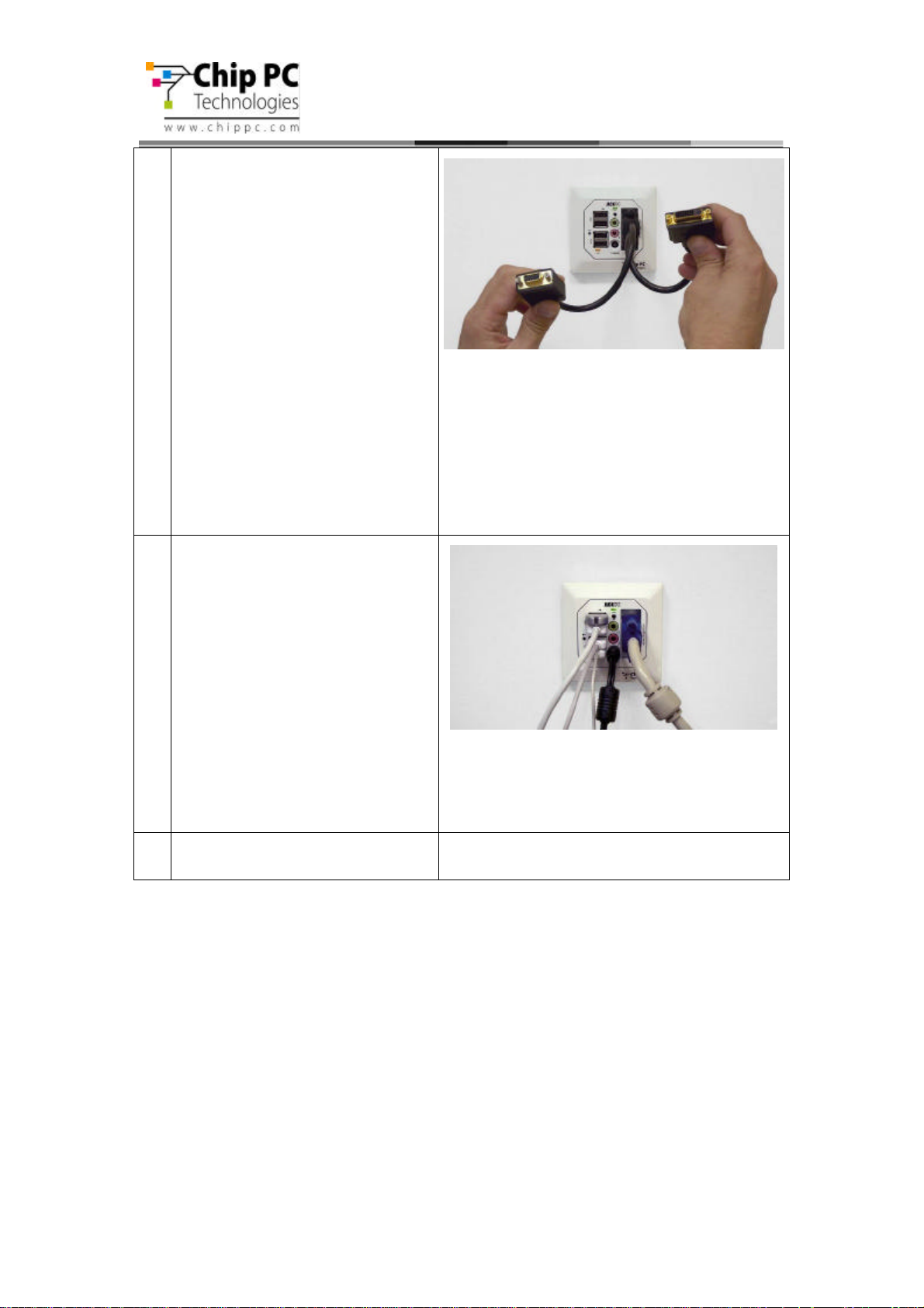
12 Connect Keyboard, Mouse, Monitor
and any other required peripheral to
device ports.
For additional instructions on how to
connect your peripheral devices, see
paragraph 3.6.
Note: In case a USB-to-PS/2
converter or USB-to single/dual
Serial ports adapter (to support serial
printers) is needed (Chip PC part
number: CPN01487).
You can connect the Jack PC to a
Wireless network using the Wireless
LAN USB dongle 802.11g (Chip PC
part number: CPN02302).
Purchase all accessories only from
Chip PC to assure compatibility, for
more details please see the
accessories list.
14
Jack PC Hardware User Manual - Training Department
Version 0506
12a Model EFI-6900 offers dual-screen
support.
In order to get this functionality,
connect a Y-cable to the DVI monitor
port.
Purchase the Y-cable only from Chip
PC to assure compatibility. (Chip PC
part number: CPN02176 - see
accessories list).
In order to connect only one VGA
monitor, you will need to use Chip
PC DVI to VGA adapter.
Purchase the DVI to VGA adapter
only from Chip PC to assure
compatibility. (Chip PC part number:
CPN02159 - see accessories list).
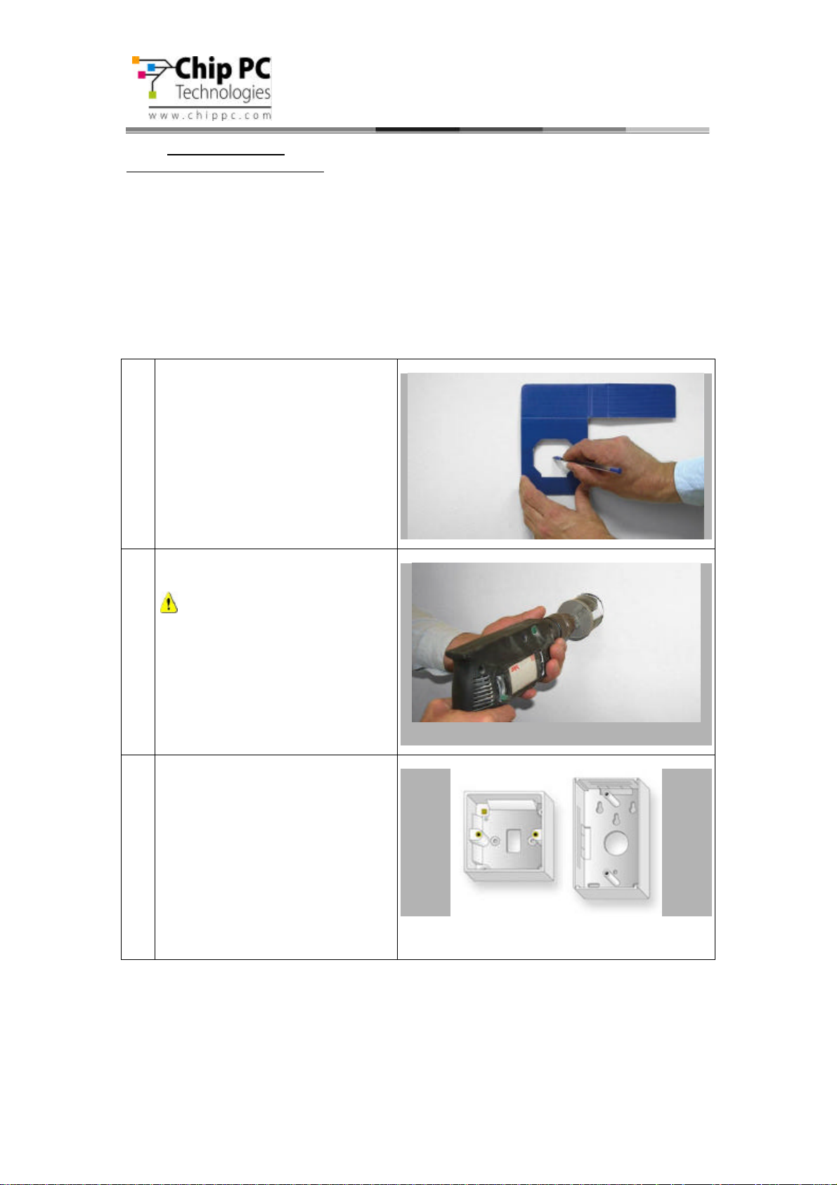
13 To power the device from an external
power source, connect the power
supply to the DC power jack.
Check that the Power/Fail LED is
illuminated in green, and that the
Link LED is lighted if not use the
troubleshooting guide.
Jack PC devices should only be
used with Chip PC-supplied
power supplies (Chip PC part
number: CPN1491 or CPN1503
or CPN1504 – see accessories
list).
Press the Reset button – and start
14
working. Enjoy!
15
Jack PC Hardware User Manual - Training Department
Version 0506
3.5 New Installation
Tools you will need for New Installation:
• Drill with 65 mm (2.6 Inch) Hole Saw
• Half-round File to trim wall cutout
• Cutter to remove LAN cable insulation
• Corona Punch-Down Tool to secure wires (Note: use only the tool supplied by Chip
PC – see accessories list for more details)
• Cloth to clean Housing contacts
• Screwdriver / Electric-screwdriver
• Extraction Tool to remove device after it was installed
1 Use the lower Cardboard template
supplied in packaging to mark the
designated wall cut out for the FlexJack Housing installation.
2 Drill the wall cut out at the
designated location.
Warning: Make sure not to drill
next to electricity/telephone lines.
Test for existence of power lines
or enforcement beams prior to
drilling the wall cutout!
2a In case you wish to install the Jack
PC externally, you can use the FlexJack External Mounting Box (Chip
PC part number CPN02172 or
CPN02173).
Insert the cable through the exiting
holes, or cut a new wire path using
one of the thinner areas.
Simply install the External Mounting
Box using standard drill and screws.
16
Jack PC Hardware User Manual - Training Department
Version 0506
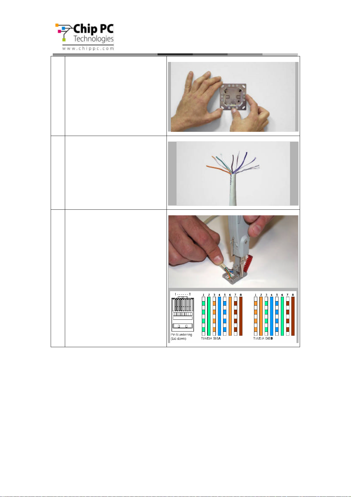
3 Trim the cut out gently and check
that the housing fits in properly.
4 Pull out the LAN cable and remove 4
cm/1.5 inch of its plastic insulation.
Separate wire pairs by color and roll
the shielding wires together.
5 Open the IDC Termination
Connector Block red cover. Secure
the wires with an Corona PunchDown Tool by using the appropriate
color scheme, according to TIA568
version A or B as shown in picture.
Note: use only the tool supplied by
Chip PC – (see accessories list for
more details)
Follow the instruction in
paragraph 6 – Wiring
Configurations for additional
information.
17
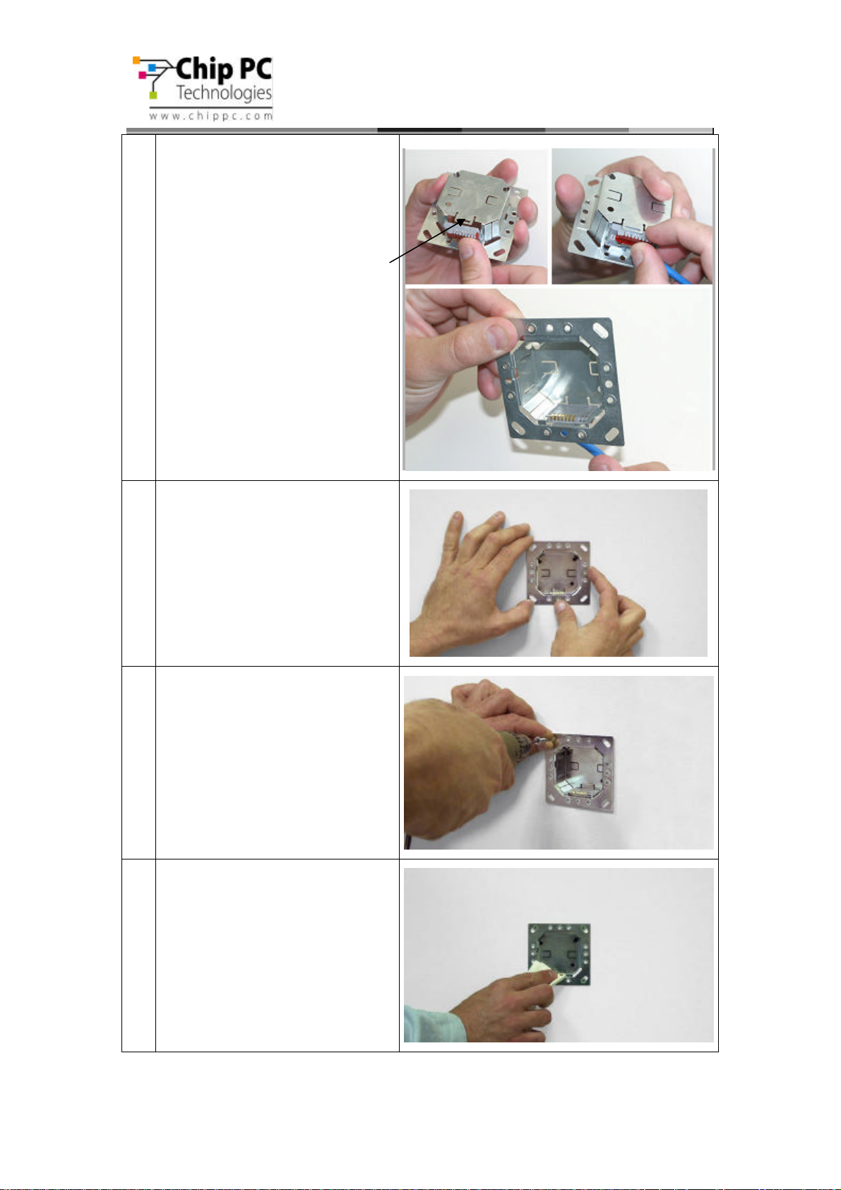
6 Close the IDC Termination
Connector Block and insert it into the
Housing bottom part until you hear a
clicking sound indicating it has
locked properly into place.
In case the Connector Block in not
locked in to position, you can slightly
bend the metal tab to create more
pressure on the Connector Block.
It is recommended to verify that
the wires are connected properly
to the Flex-Jack terminal block
before securing it in to the wall!
See chapter 6 for more
information.
Jack PC Hardware User Manual - Training Department
Version 0506
6 Place the Flex-Jack Housing inside
the Jack hole. Trim wall cutout if
necessary.
7 Make sure that the Flex-Jack
Housing is fully inserted, levelheaded and that the Housing
contacts are located at the bottom
part as shown in picture.
Secure with 4 screws.
8 Gently clean the Flex-Jack Housing
contacts from dust, debris and other
objects.
18

Jack PC Hardware User Manual - Training Department
Version 0506
9 Test the Flex-Jack has current
before you continue.
The Jack PC device should be
inserted with the contacts (shown in
the picture) facing downwards, as
shown in the picture.
10 Insert the Jack PC device into the
Housing until you hear a clicking
sound indicating the device has
locked properly into place.
Verify device locking by gently
pulling device outwards.
Where using PoE check now to see
that the Power/Fail LED is
illuminated in green, and that the
Link LED is lighted if not use the
troubleshooting guide.
If the device is not locked, remove
the unit, and make sure that the latch
locking hole is intact and is free from
foreign objects. If you are still unable
to lock the unit, try using a different
Metal Housing.
12 Connect Keyboard, Mouse, Monitor
and any other required peripheral to
device ports.
For additional instructions on how to
connect your peripheral devices, see
paragraph 3.6.
Note: In case a USB-to-PS/2
converter or USB-to single/dual
Serial ports adapter (to support serial
printers) is needed (Chip PC part
number: CPN01487).
You can connect the Jack PC to a
Wireless network using the Wireless
LAN USB dongle 802.11g (Chip PC
part number: CPN02302).
Purchase all accessories only from
Chip PC to assure compatibility, for
more details please see the
accessories list.
19
 Loading...