


Contents
1 Getting Started with Time Recording ................................................................................................... 5
1.1 Introduction .................................................................................................................................. 5
1.2 Installation .................................................................................................................................... 5
1.3 Defining Global Settings ............................................................................................................... 6
1.4 Creating Users .............................................................................................................................. 6
1.5 Creating User Cards and Contactless User Chips ......................................................................... 7
1.6 Using the Transport Card ............................................................................................................. 8
1.6.1 Formatting the Transport Card ............................................................................................ 8
1.6.2 Reading Clocking Data from the Transport Card .................................................................. 8
1.7 Working with Network Terminals and PC Time Clock (Server) .................................................... 9
1.7.1 Single Installation of PC Time Clock ...................................................................................... 9
1.7.2 Network Terminals and PC Time Clock (Server) ................................................................. 10
1.7.3 Exchanging Data with Network-Terminals ......................................................................... 11
2 CHIPDRIVE® mobile 910 ..................................................................................................................... 12
2.1 Software Version and Language ................................................................................................. 12
2.2 Administrative Tasks on the CHIPDRIVE® mobile ....................................................................... 12
2.2.1 Setting the Date and Time .................................................................................................. 12
2.2.2 Calibrating the Clock ........................................................................................................... 13
2.2.3 Daylight Saving Time .......................................................................................................... 13
2.2.4 Changing the LCD Contrast ................................................................................................. 14
2.2.5 Changing the Terminal ID ................................................................................................... 14
2.2.6 Transferring Clocking Data to a PC ..................................................................................... 15
2.3 Clocking on the CHIPDRIVE® mobile .......................................................................................... 16
2.3.1 Clocking In .......................................................................................................................... 16
2.3.2 Clocking In, Changing the Project ....................................................................................... 16
2.3.3 Clocking In, Changing the Project and Activity ................................................................... 16
2.3.4 Clocking In, Changing the Activity Only .............................................................................. 16
2.3.5 Clocking Out ....................................................................................................................... 16
2.3.6 Changing the Project, Changing the Project and/or Activity .............................................. 17
2.3.7 Correcting Input Errors ....................................................................................................... 17
2.3.8 Project Number Zero –-Activity Number Zero ................................................................... 17
2.3.9 Canceling a Clocking Entry .................................................................................................. 17
2.4 Changing Batteries, Device Maintenance .................................................................................. 17
2.5 Technical Data ............................................................................................................................ 18
2.6 Waste Disposal ........................................................................................................................... 18
3 PC Time Clock Server .......................................................................................................................... 18
3.1 Installation .................................................................................................................................. 18
CHIPDRIVE® Time Recording 2

3.2 Configuring the Windows Firewall ............................................................................................. 19
3.3 Settings ....................................................................................................................................... 19
3.3.1 Language and Color Scheme .............................................................................................. 19
3.3.2 Server Role and Data Transfer ............................................................................................ 20
3.3.3 Port Number ....................................................................................................................... 20
3.3.4 Email Settings for the Central Server ................................................................................. 21
3.3.5 Email Settings for the Client Server .................................................................................... 22
3.4 Creating Clients .......................................................................................................................... 23
3.4.1 Time Recording, CHIPDRIVE® Network-Terminals, PC Time Clock ..................................... 24
3.4.2 Email Clients ....................................................................................................................... 24
3.4.3 CHIPDRIVE® Terminals and PC Time Clock using DDNS ..................................................... 25
3.4.4 CHIPDRIVE® Fingerprint C2................................................................................................. 25
3.5 Using the PC Time Clock Server Service ..................................................................................... 27
3.5.1 Benefit of the Service ......................................................................................................... 27
3.5.2 Installing and Starting the Service ...................................................................................... 27
3.5.3 Changing the Log On Account for the Service .................................................................... 27
3.6 Using the Time Recording Module ............................................................................................. 28
3.6.1 Description ......................................................................................................................... 28
3.6.2 Prerequisites ....................................................................................................................... 28
3.7 Interface for CHIPDRIVE® Driver Card Solutions ........................................................................ 29
4 PC Time Clock ..................................................................................................................................... 29
4.1 Description ................................................................................................................................. 29
4.2 Installation .................................................................................................................................. 30
4.3 Settings ....................................................................................................................................... 30
4.3.1 TCP/IP – HTTP ..................................................................................................................... 31
4.3.2 Email ................................................................................................................................... 31
4.3.3 Single Installation – Without Server ................................................................................... 32
4.4 Using the Basic Features ............................................................................................................ 33
4.4.1 Clocking and Vacation Statistics ......................................................................................... 33
4.4.2 Reading Data from the Transport Card and European Driver Card ................................... 34
4.5 Using Advanced Features ........................................................................................................... 34
5 CHIPDRIVE® CDO920-DI Network Terminal ....................................................................................... 35
5.1 Description ................................................................................................................................. 35
5.1.1 Supported Cards ................................................................................................................. 35
5.1.2 Memory for Offline Mode .................................................................................................. 35
5.1.3 Memory for Data Backup ................................................................................................... 35
5.2 Wall Mounting and Cabling ........................................................................................................ 35
5.3 Technical Data ............................................................................................................................ 37
CHIPDRIVE® Time Recording 3

5.4 Cleaning the Unit ........................................................................................................................ 37
5.5 Waste Disposal ........................................................................................................................... 38
5.6 Configuring Device Settings ........................................................................................................ 38
5.6.1 Create Service Chip or Service Card ................................................................................... 38
5.6.2 IP Address ........................................................................................................................... 38
5.6.3 LCD Contrast ....................................................................................................................... 39
5.6.4 Backlight ............................................................................................................................. 40
5.6.5 Sounds ................................................................................................................................ 40
5.6.6 Additional Settings for Offline Operation ........................................................................... 40
5.7 Configuring Settings using the Web Interface ............................................................................ 41
5.8 Hardware Reset .......................................................................................................................... 45
5.9 Registering the Terminal on the DNS Server .............................................................................. 46
5.10 Checking the Availability of the Terminal in the Network ......................................................... 46
5.11 Clocking Data on the Terminal ................................................................................................... 47
5.11.1 Rapid Clock-In/Out and Vacation Information ................................................................... 47
5.11.2 Projects and Activities ........................................................................................................ 47
5.12 Reading Data from a Digital Driver Card .................................................................................... 48
5.13 Using Transport Card 256 ........................................................................................................... 49
5.13.1 Reading Data from the CHIPDRIVE® mobile at a Terminal ................................................. 49
5.13.2 Transferring a Backup from a Terminal to the PC .............................................................. 49
5.13.3 Transferring Offline Clocking Entries from a Terminal to the PC ....................................... 49
6 CHIPDRIVE® Fingerprint C2 ................................................................................................................ 50
6.1 Device Description ...................................................................................................................... 50
6.1.1 Overview ............................................................................................................................. 50
6.1.2 Technical Data .................................................................................................................... 51
6.1.3 Using the Fingerprint Sensor .............................................................................................. 52
6.2 Communicating with PC Time Clock Server ............................................................................... 52
6.2.1 Terminal Settings ................................................................................................................ 52
6.2.2 Computer Settings .............................................................................................................. 53
6.3 Additional Terminal Settings ...................................................................................................... 54
6.3.1 Date and Time .................................................................................................................... 54
6.3.2 Display Setup ...................................................................................................................... 54
6.3.3 Advanced Setup – FP Precision .......................................................................................... 54
6.3.4 Advanced Setup – In/Out Att. Setup .................................................................................. 55
6.3.5 Advanced Setup – Clock Options ........................................................................................ 56
6.4 Creating Users ............................................................................................................................ 57
6.5 Managing User Data for Several Terminals (Synchronization)................................................... 58
6.6 Clocking Data on the Terminal: In – Out – Change Project ........................................................ 59
CHIPDRIVE® Time Recording 4
CHIPDRIVE® Time Recording
1 Getting Started with Time Recording
1.1 Introduction
CHIPDRIVE® Time Recording is a flexible and scalable time recording system that supports entries from
battery-operated terminals (CHIPDRIVE® mobile 910), network terminals (CHIPDRIVE® 920DI and
CHIPDRIVE® Fingerprint C2), as well as installations of the PC Time Clock software. Besides the core Time
Recording software, the list of required software components depends on your choice of hardware. If
you intend to use CHIPDRIVE® mobile terminals only, there is no need to install any other software.
Network devices require the installation of PC Time Clock Server to coordinate the transfer of data
between Time Recording and the terminals in use.
1.2 Installation
To install CHIPDRIVE® Time Recording, please use the software CD provided with your Time Recording
solution package. Once the software is installed, including the driver for the card reader, you can
optionally download the latest update from the CHIPDRIVE® website at www.chipdrive.de, and
overwrite the existing installation.
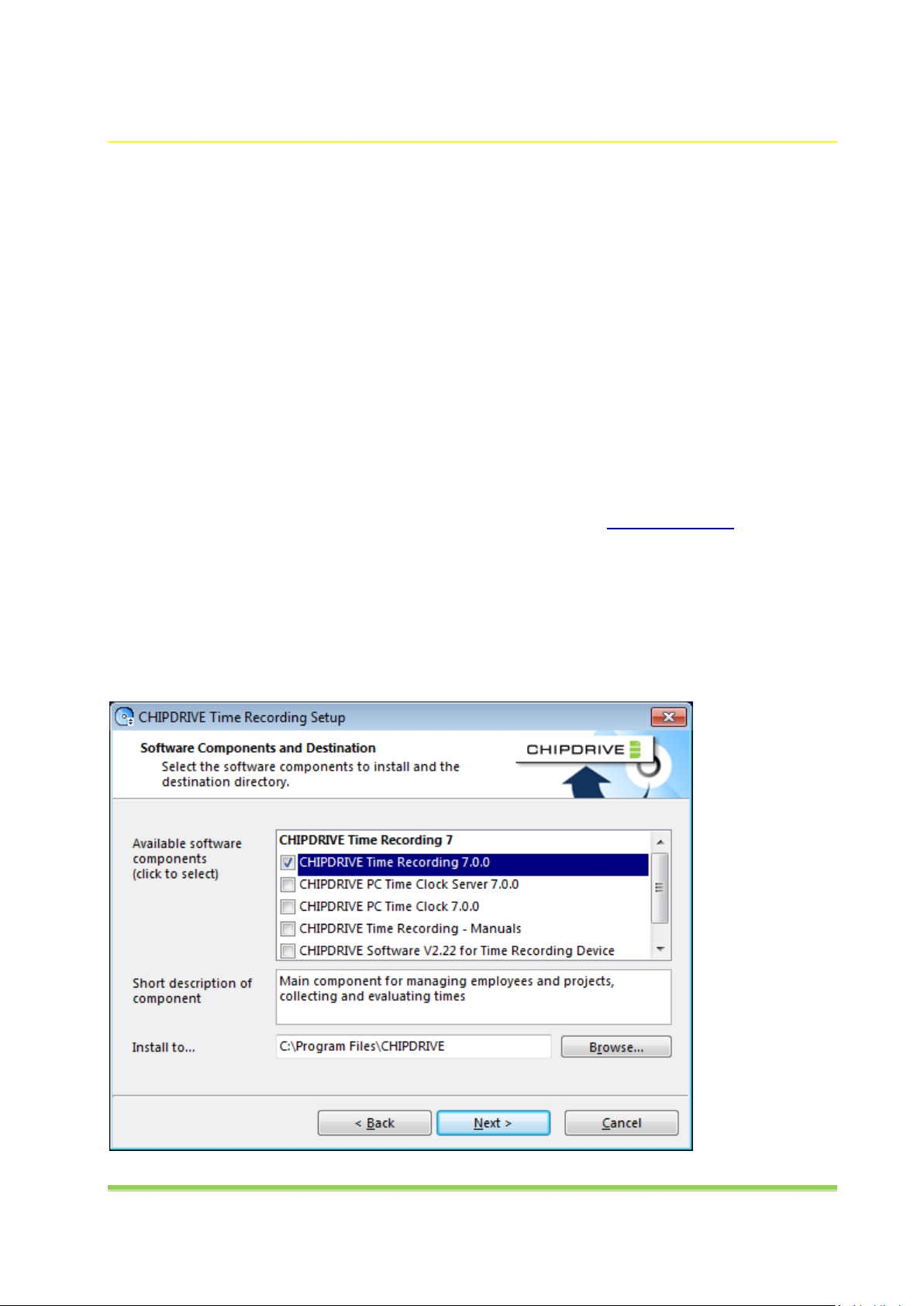
The selection of the components to be installed depends on whether you wish to use network terminals
and/or PC Time Clock Server installations, or CHIPDRIVE® mobile 910 devices only. Before you start
setting up a network installation, consider whether you would like to install the Time Recording
software and the PC Time Clock Server software on the same computer, or whether you would rather
install PC Time Clock Server on a separate server machine that runs 24/7.
CHIPDRIVE® Time Recording 5
You only need to select CHIPDRIVE mobile software if you intend to use CHIPDRIVE mobile 910 devices,
and if the firmware on your devices is older than version 2.22, or if you wish to modify the language
settings. The firmware version is displayed on the start screen when you switch the device on. You can
tell which language the interface is currently set to by the displayed date and disk space details.
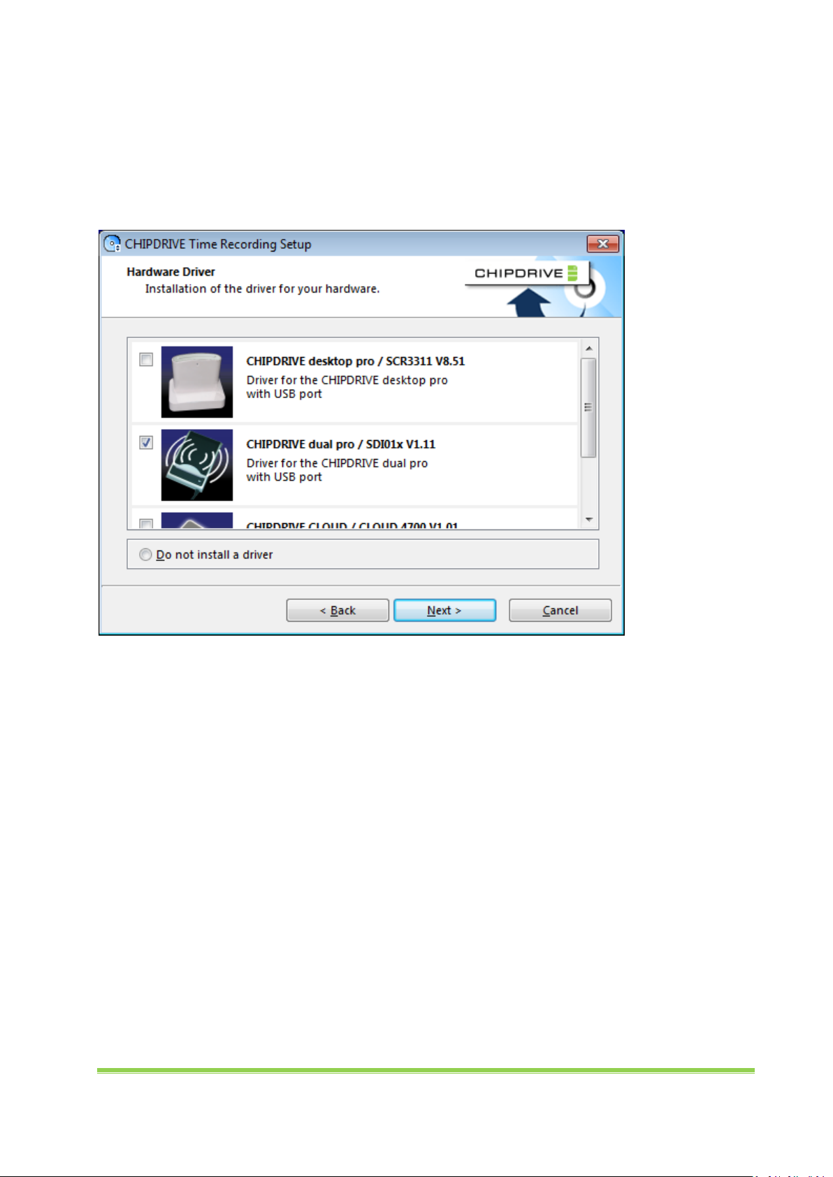
Click Next to select the driver for the card reader. Continue clicking Next to proceed with the setup
wizard, and select Finish when done.
1.3 Defining Global Settings
Before you start creating users, launch the Time Recording software, and configure the main global
settings, e.g. Pay Period, Time Format, Address Format, and Settings for Night Shift. For more details,
read the help section on "Global Settings." Use the Extras / Color scheme feature to customize the
appearance of the user interface to fit your personal preferences.
1.4 Creating Users
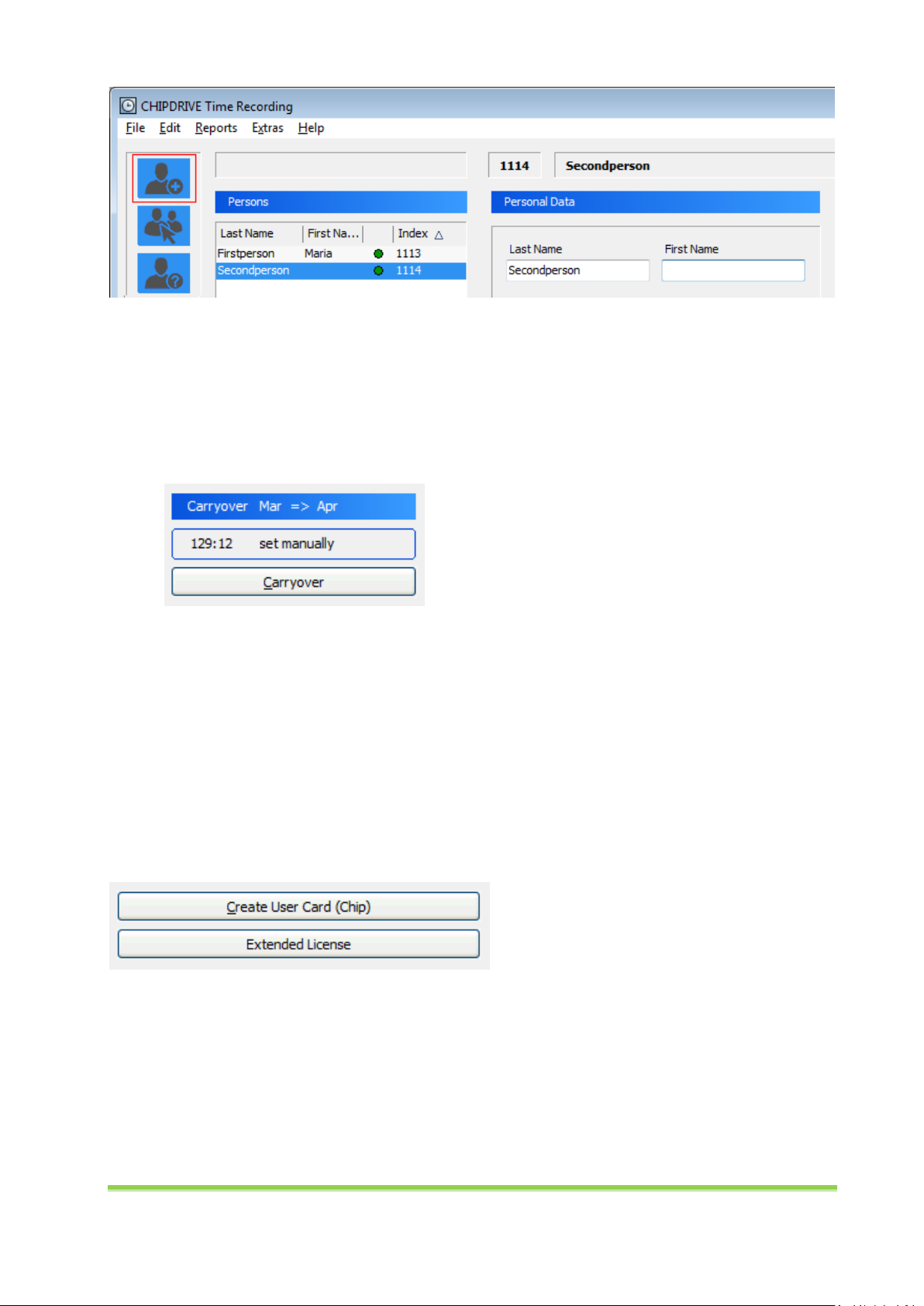
To create a person, select File / New Person from the main menu, or click on the respective button in
the toolbar, then enter the person's last and first name. Any additional details about the person are
optional. Work time, breaks, carryover, and various advanced settings can be configured either
immediately after you have created the person or at a later point in time. For more details on the
available settings, please refer to the help documentation.
CHIPDRIVE® Time Recording 6
If a user is not created on the first day of a month, a message will appear, allowing you to create
automatic Extra Free entries indicating the reason before entry date for all previous days in this
particular month in order to avoid a negative hourly balance as per the creation date. Alternatively, you
could also manually add In and Out entries for the days before the creation date. Or you can manually
enter a respective negative carryover for the immediate day before the creation date to achieve a
correct hourly balance as per the creation date.
If you are creating several persons, you can save time by using an Excel spreadsheet. To do so, first
generate an Empty Excel File for Person Import (see File / Personnel Administration). Then enter the
persons' data into the file, or copy it from any source into the respective columns. The steps are
described in more detail in the help documentation in the "Personnel Administration / Importing and
exporting personnel data" section.
1.5 Creating User Cards and Contactless User Chips
To assign an original CHIPDRIVE® User Card or a contactless User Chip to a person, insert the card into
the card reader or place the chip on the reader. This enables the Create User Card (Chip) button. Click
on the button, and remove the card/contactless chip when prompted.
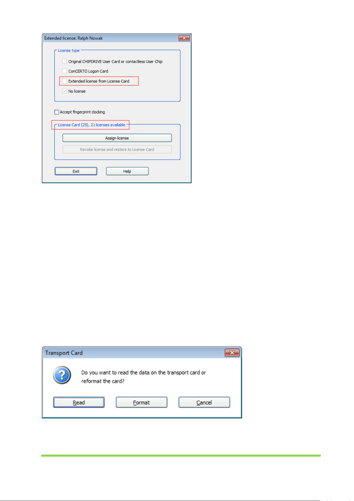
If you intend to use CHIPDRIVE® Fingerprint C2 terminals only, an extended license from a CHIPDRIVE®
Time Recording License Card is required for each person. To assign a license to a person, click on the
Extended license button, and insert the License Card into the card reader. By selecting Assign license
the Extended license from License Card checkbox is enabled, and the number of available licenses on
the card is decreased by 1. Then activate the Accept fingerprint clocking checkbox. Fingerprint clocking
can also be enabled for persons with an original CHIPDRIVE® User Card, a contactless User Chip, or a
ConCERTO Logon Card. In these cases, no extended license is required.
CHIPDRIVE® Time Recording 7
If you are using extended licenses, you can also assign chips that are not original CHIPDRIVE® or
ConCERTO® products. See chapter 5.1.1 for a list of the supported products.
1.6 Using the Transport Card
1.6.1 Formatting the Transport Card
If you are using CHIPDRIVE® mobile 910 devices, you will need a Transport Card to transfer clocking data
from the mobile device to your PC, and to configure terminal settings. The Transport Card can also be
used to import the clocking data from 920-DI network terminals (e.g. for recovery purposes in the event
of network failure). The Transport Card must be formatted before use. To do this, switch the Time
Recording software into Edit / Clocking mode (= default view upon application start), insert the
Transport Card in the card reader, and select Format when prompted.
1.6.2 Reading Clocking Data from the Transport Card
To transfer data from a Transport Card to the PC, set CHIPDRIVE® Time Recording to the Edit / Clocking
mode, and insert the Transport Card into the card reader. You will then be asked if you wish to read the
data on the Transport Card. Click Read, and wait until you are prompted to remove the card.
CHIPDRIVE® Time Recording 8
1.7 Working with Network Terminals and PC Time Clock (Server)
To connect CHIPDRIVE Time Recording with network terminals and/or installations of PC Time Clock,
select File / Administration / PC Time Clock - Settings.
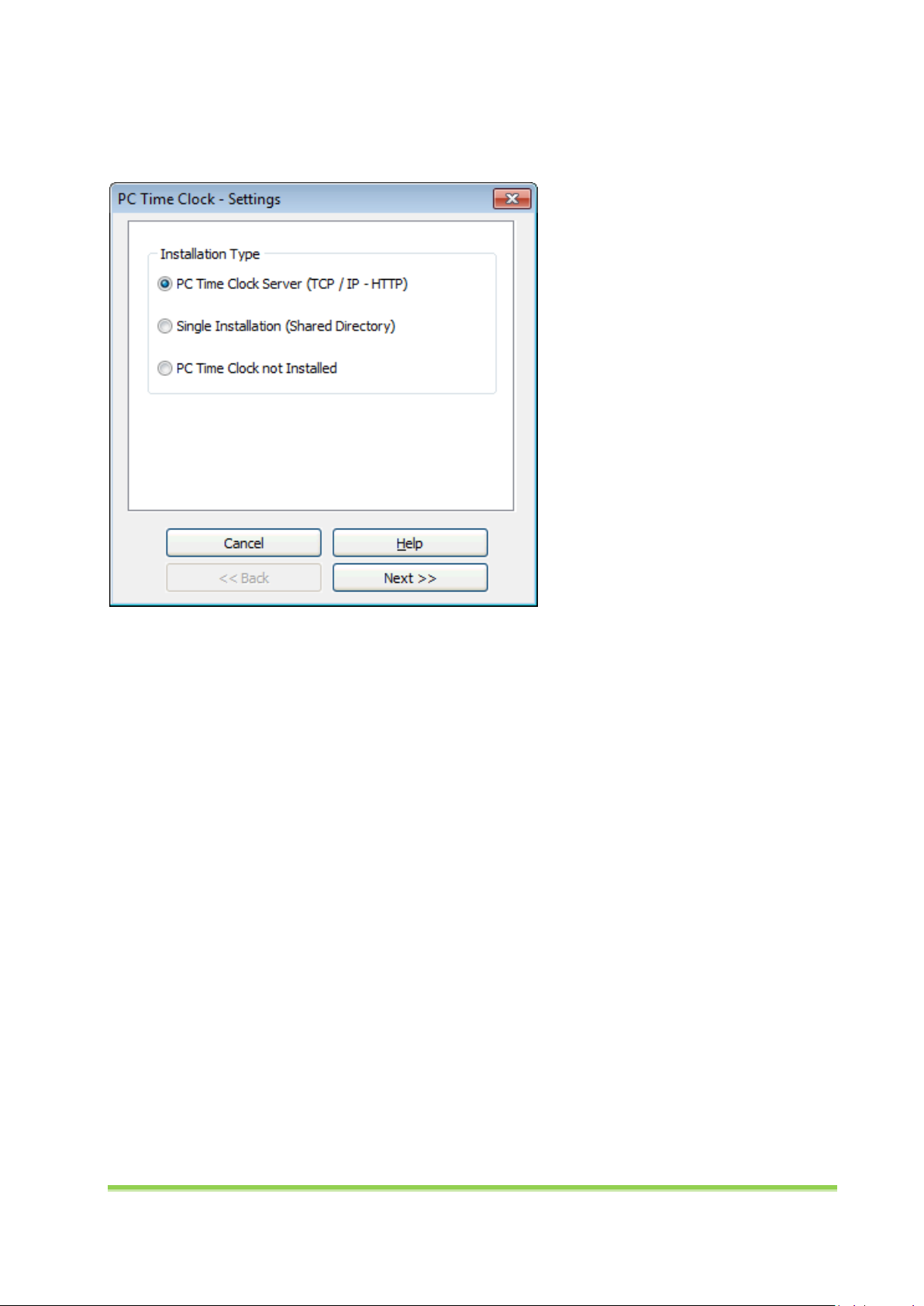
1.7.1 Single Installation of PC Time Clock
If required, you can run a single installation of PC Time Clock without an additional PC Time Clock Server
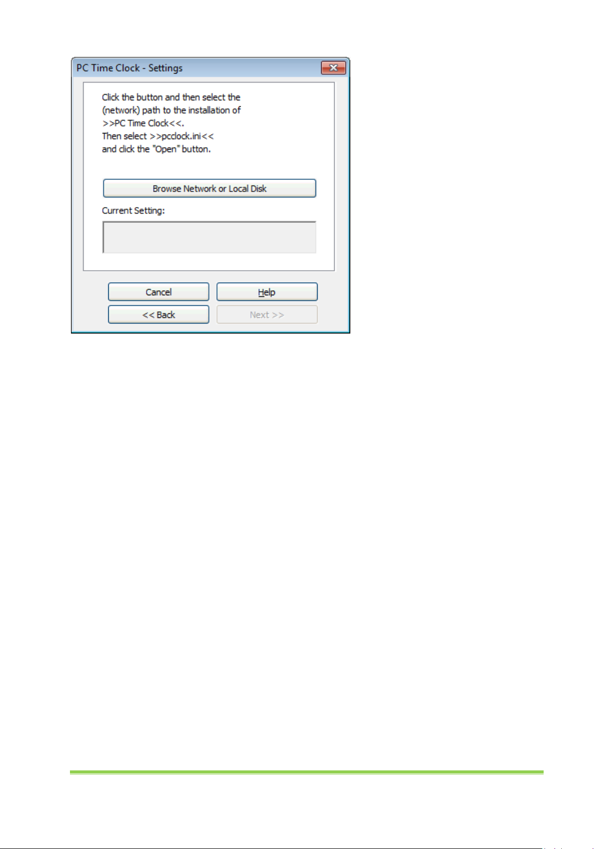
installation. If the software is installed on a separate machine, you need to share the network directory
containing the "pcclock.ini" file along with all subdirectories. Assuming that you have installed PC Time
Clock in the Programs folder of your local hard drive, the "pcclock" file is by default located at
"C:\ProgramData\CHIPDRIVE\Time Recording x\pcclock" (Windows Vista or later) or "C:\Documents and
Settings\All Users\Application Data\CHIPDRIVE\Time Recording x\pcclock" (Windows XP).
Select Browse Network or Local Disk to open the "pcclock.ini" file, and create a connection.
CHIPDRIVE® Time Recording 9
1.7.2 Network Terminals and PC Time Clock (Server)
If you plan to use network terminals and/or several installations of PC Time Clock, you need to install PC
Time Clock Server. The following steps are based on the assumption that PC Time Clock Server has
already been installed (see chapter 3.1), and that the computer running Time Recording has been
entered as client (see chapter 3.4.1).
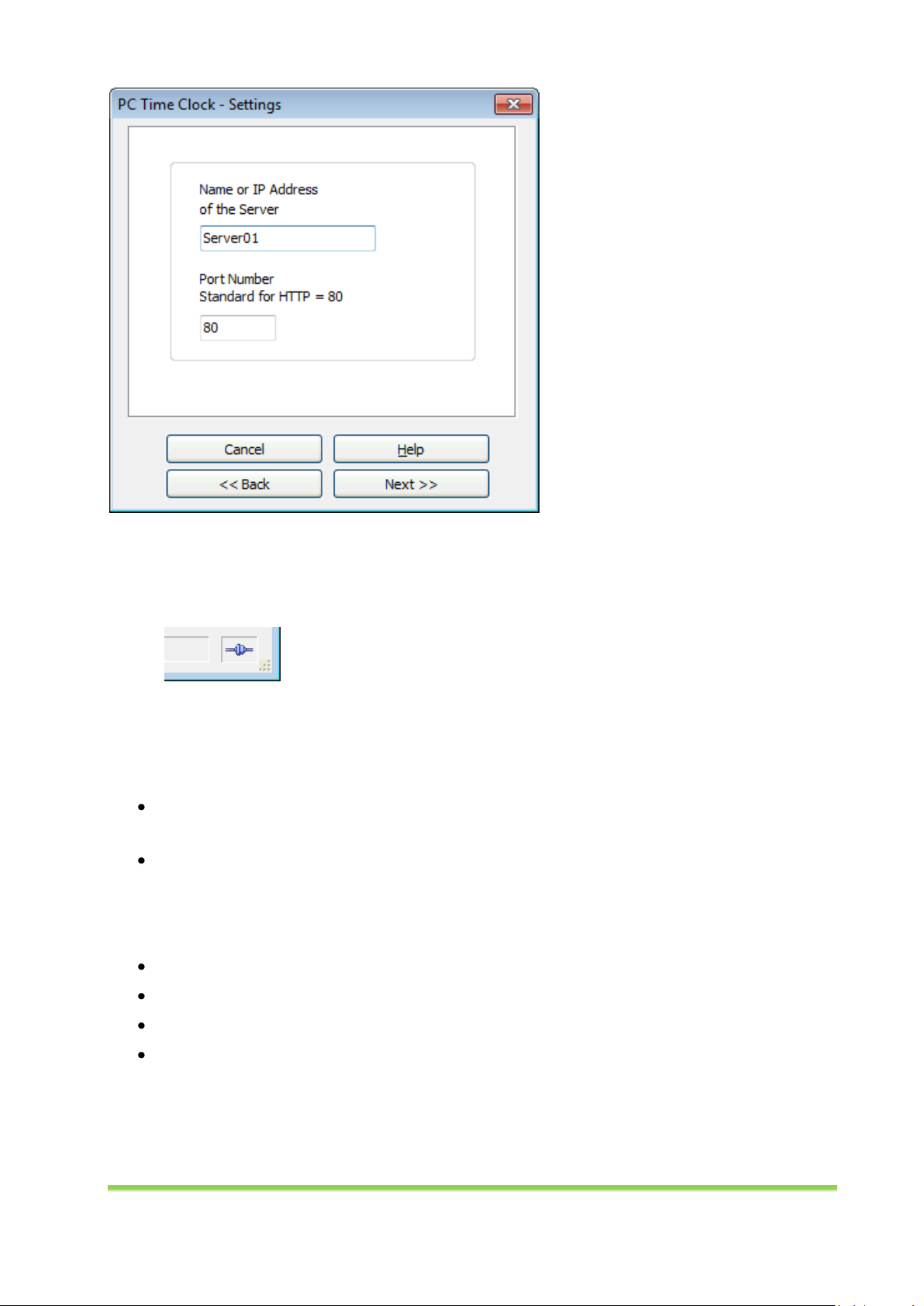
Select PC Time Clock Server (TCP / IP - HTTP) on the first page of the settings wizard. On the next page,
enter the name or IP address of the computer that PC Time Clock Server is installed on. The default port
number is 80. It has to match the port number configured for PC Time Clock Server.
CHIPDRIVE® Time Recording 10
On the last page of the settings wizard, you can enable or disable the option to enter project numbers
and activity numbers for all CHIPDRIVE® network terminals. When the settings are complete, click
Finish. You should now see a connection symbol on the bottom right.
1.7.3 Exchanging Data with Network-Terminals
The data transfer which takes place between CHIPDRIVE Time Recording and CDO920-(DI) terminals and
PC Time Clock installations is bi-directional.
The terminals receive information from Time Recording via PC Time Clock Server regarding the
hourly balances and vacation statistics of individual persons.
Time Recording receives the current clocking data.
The frequency of the automatic data synchronization depends on whether the Time Recording Module
is running on the server computer (see chapter 3.6). If this is the case, data is synchronized within a few
seconds. Otherwise data is exchanged only:
When launching Time Recording.
When selecting Report / Current Overview.
When selecting File / Read Data from PC Time Clock.
At 1 AM if Time Recording is running at that time.
CHIPDRIVE® Time Recording 11
2 CHIPDRIVE® mobile 910
2.1 Software Version and Language
Before you start using the device, please ensure that the firmware is up-to-date (check start screen; the
current version is 2.22) and that the user interface is set to the desired language (check date display). If
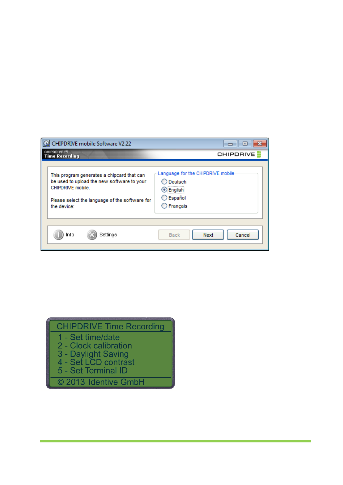
the firmware or language setting needs updating, launch the CHIPDRIVE mobile software on the PC. To
change the language for the CHIPDRIVE mobile software interface, click on the Options button. The
language setting for the device can be selected in the Language for CHIPDRIVE mobile section. Click
Next to start the wizard which will walk you through the steps required to upload the current firmware
to your device using the Transport Card and to restore the Transport Card to its original state
afterwards.
2.2 Administrative Tasks on the CHIPDRIVE® mobile
2.2.1 Setting the Date and Time
To define settings on the CHIPDRIVE® mobile, insert a formatted Transport Card, and then press the
green OK button to activate the configuration menu. To format the Transport Card, see chapter 1.6.1.
The CHIPDRIVE® mobile has an automatic calibration feature for the clock that calculates a calibration
value based on the interval between, and a deviation value that results from, two separate clock setting
procedures. The accuracy of this value depends both on the accuracy of the time that was set and on
the interval between the two settings. If the deviation is minor, you should wait a few weeks before
CHIPDRIVE® Time Recording 12
making a correction. The clock will not be recalibrated if the interval between two setting procedures is
less than two weeks.
Important: Immediately after setting the date and time for the first time, the calibration value should be
reset to zero. This prevents the creation of an inaccurate calibration value resulting from a large time
difference in relation to the manufacturer setting.
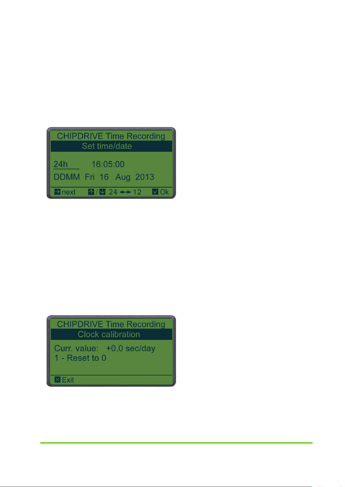
To set the date and time, open the main menu and select item Set time/date. The Set time/date screen
initially displays the 24-hour or AM/PM time format. To change the format, press either the up or down
arrow key. Then use the right arrow key to select the hour and adjust it (if necessary) using the arrow
keys. Next, select the minutes and set them in the same manner.
With the DDMM function, you can customize the date format (DDMM stands for day/month, MMDD
for month/day). Once you have checked and/or set the month and date, monitor the seconds on a clock
which is as accurate as possible, and press the green OK key at exactly the set time.
2.2.2 Calibrating the Clock
Select the Calibrate clock menu item to display the current calibration value, and reset it to 0. After
setting the date and time for the first time, the calibration value should be reset. Otherwise the
automatic mechanism would use the calibration value to balance the deviation between the new
correct time and the time value set at the manufacturer which is not always completely accurate. To
reset the value to 0, press the 1 key on your keypad, and then return to the main menu by pressing the
red Cancel key.
2.2.3 Daylight Saving Time
The CHIPDRIVE® mobile automatically switches from daylight saving time to standard time, and from
standard time to daylight saving time. The setting follows the default for the EU, whereby the change
CHIPDRIVE® Time Recording 13
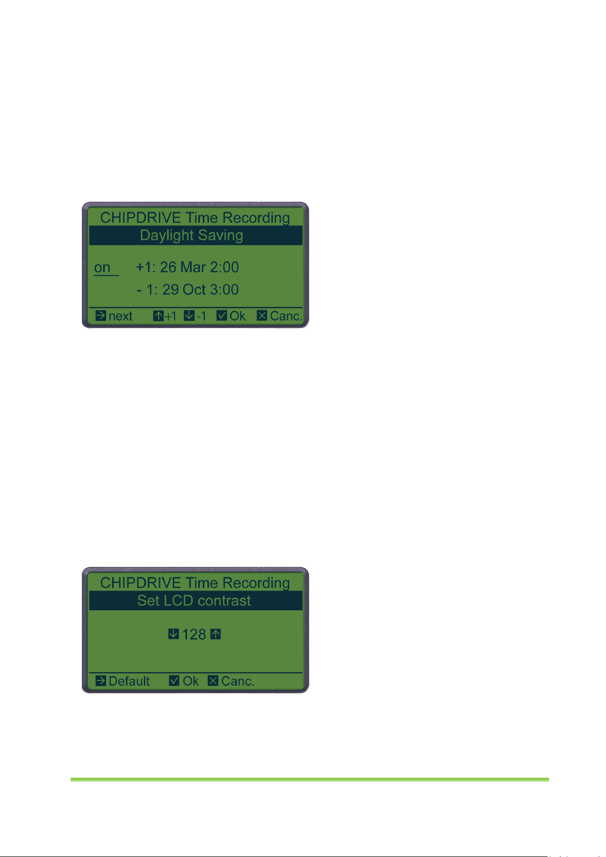
from standard (winter time) to daylight saving time (summer time) is made on the last Sunday in March
at 2:00 a.m. by moving the clock forward by one hour. When changing from daylight saving time to
standard time, the clock is set back by one hour on the last Sunday in October at 3:00 a.m. This setting is
automatically updated for the current year the first time you switch the device on in the new year. If you
are using the device in a country that does not use this rule, select Daylight Saving in the main menu to
switch the automatic mechanism off, and set the date and time for the automatic conversion. Please
note that this manual setting only applies to the current year, and will therefore have to be reset every
year before the clocks change for the first time.
To disable the automatic conversion, leave the setting on enabled. Change the setting to off using the
up or down arrow key. Use the right arrow key to access the day, month and time for switching from
standard to daylight saving time (+1), then go to the next line (-1) which contains the date and time for
switching from daylight saving to standard time. These settings are not applied until you confirm them
by pressing the OK key.
2.2.4 Changing the LCD Contrast
If the contrast on the display of your CHIPDRIVE® mobile is too low, or if there are distracting horizontal
or vertical lines (excessive contrast), choose Set LCD contrast in the main menu. Using the arrow keys,
you can increase (up arrow) or decrease (down arrow) the contrast in small increments. The right arrow
key resets the contrast to the default value 128. Press the OK key to apply the setting.
Note: The contrast also depends on the temperature of the surrounding environment. It will decrease in
a cold environment, but will return to a normal level when the device acquires room temperature again.
2.2.5 Changing the Terminal ID
Every device should have a unique device number or terminal ID, especially if several devices or
additional installations of CHIPDRIVE® PC Time Clock are in use. This number is an integral part of each
CHIPDRIVE® Time Recording 14
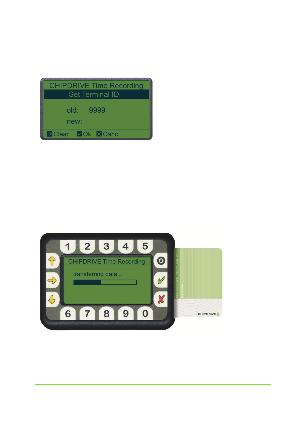
clocking data entry made on that device. This means that the PC can track exactly who made a clocking
entry, when, and where (i.e. on which device). The terminal ID can also be used as a project number or
activity number.
To set the terminal ID, select Set Terminal ID (5) in the main menu. Enter a value between 1 and 9999,
and confirm with OK.
2.2.6 Transferring Clocking Data to a PC
To transfer clocking data from the CHIPDRIVE® mobile to a PC, insert a formatted Transport Card M256
into the mobile device to automatically start the copy process. One Transport Card can hold data from
several devices. Therefore, it is possible to collect data from several devices one after the other. Before
the data is copied, the device automatically checks if there is enough storage space left on the card. One
Transport Card can store a maximum of 2040 clocking entries, with up to 4-digit project numbers, but
without activity numbers. Clocking entries with longer project numbers and/or activity numbers take up
twice the storage space, and reduce the maximum clocking entry capacity respectively. See chapter
1.6.2 on how to read data to the PC.
Note: Once the clocking entry data has been transferred, the device memory is deleted. In case a
Transport Card is lost, the data can be transferred directly from the individual user cards to the PC. With
Time Recording software running, insert one user card after the other. You will be asked each time
whether you wish to read the data from the user card. A user card contains up to 120 of the latest
clocking entries.
CHIPDRIVE® Time Recording 15
2.3 Clocking on the CHIPDRIVE® mobile
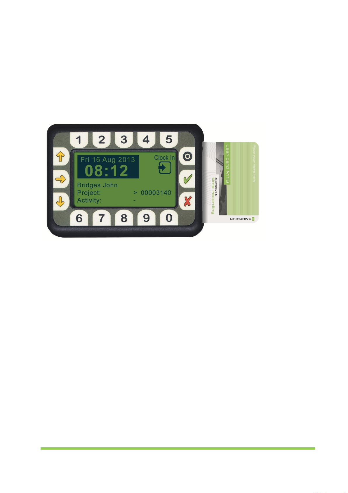
2.3.1 Clocking In
A Clock In entry normally follows a Clock Out entry, and is therefore automatically entered when you
insert the user card (provided the last entry was Clock Out). The clocking entry is executed immediately,
and confirmed with an acoustic signal. Simply remove the card without pressing any key.
If you forgot to make the last Clock Out entry, the device automatically registers a Clock Out entry when
the user card is inserted again. In this case it is necessary to change the entry to a Clock In entry by
pressing the yellow right arrow key.
2.3.2 Clocking In, Changing the Project
To register a Clock In entry and enter a project number, insert the user card, and confirm that Clock In is
displayed at the top right of the display. If not, press the yellow right arrow key to change it from Clock
Out to Clock In. Now enter the maximum 8-digit project number, and confirm by pressing the green OK
key.
2.3.3 Clocking In, Changing the Project and Activity
To Clock In with a change of project and activity, please proceed as described in the previous section.
After confirming the project number with OK, or the yellow down arrow key, enter the activity number,
and confirm your entry with the green OK key.
2.3.4 Clocking In, Changing the Activity Only
To change only the activity number for a Clock In entry, skip the project number input by pressing the
down arrow key (or OK), and enter the activity number. Confirm your entry by pressing the OK key.
2.3.5 Clocking Out
The Clock Out entry is normally made after a Clock In or Change Project entry. After inserting the user
card, make sure that the display shows Clock Out. If not, change the Clock In entry type to Clock Out by
pressing the yellow right arrow key. If this is not necessary (because Clock Out is already displayed)
simply remove the card. The clocking entry will have already been made before the acoustic tone.
CHIPDRIVE® Time Recording 16
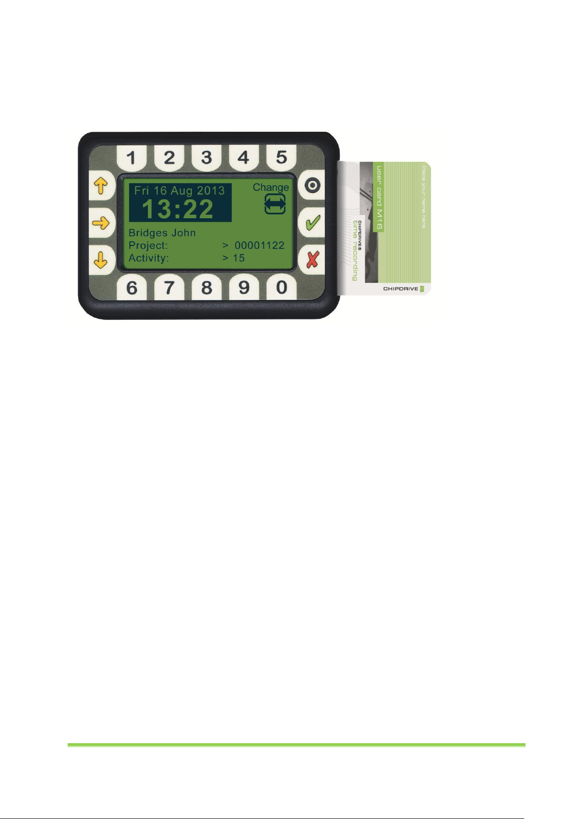
2.3.6 Changing the Project, Changing the Project and/or Activity
A project change normally follows a Clock In or Change Project clocking entry. In both cases the device
records a Clock Out entry when you insert the card. You can change this to a Change Project entry by
entering a project number and/or an activity number (see Clock In entry).
2.3.7 Correcting Input Errors
When entering a project or activity number you can always delete the last digit using the right arrow
key. To delete the number completely, press the red Cancel key.
2.3.8 Project Number Zero –-Activity Number Zero
If you want to stop working on a project or activity without moving on to another project (or activity),
you can enter 0 next to a Clock In or Change Project entry. The zero stands for "not assigned to any
project (any activity)", and the next time you insert the user card the zero project (or zero activity) will
be displayed with a dash.
2.3.9 Canceling a Clocking Entry
If you are not sure whether you have already clocked in/out, you can check this by inserting your user
card. If the device shows a Clock Out, although you wanted to clock in (or vice versa), you can cancel the
unintended entry by pressing the red Cancel button.
2.4 Changing Batteries, Device Maintenance
When the BATTERY LOW message appears on the display, the batteries need to be changed. Two AAA
or MICRO batteries are required. You should always replace both batteries at the same time. Clean the
unit with a soft, damp, lint-free cloth. To remove stubborn dirt, moisten the cloth with a few drops of
ethyl alcohol. Frequent use of dirty cards may cause the card reader to malfunction. To prevent this,
ensure that the cards are kept clean and dry at all times.
CHIPDRIVE® Time Recording 17

2.5 Technical Data
Designation
Battery-operated card reader for I²C memory cards with display,
keyboard, and integrated memory
Programming
Software via I²C memory card
Power supply
2 x AAA alkaline batteries 1.5 V / CR 1620 backup
Power consumption
(operating)
Ib <= 15 mA
Power consumption
(standby)
Is <= 30 μA
Max. battery life
Approx. 50 h continuous operation / 2 years in standby
Operating temperature
+10°C … +35°C
Storage temperature
0°C … +50°C
Relative humidity
Non-condensing
Display resolution
128 x 64 pixels
Memory
EEPROM, max. 256 Kb
Contact material
Gold-plated, min. 100,000 cycles
Dimensions
78 x 108 x 21 mm
Weight (without batteries)
150 g
Environmental guidelines
WEEE, RoHS
2.6 Waste Disposal
Products marked with the WEEE disposal symbol require professional disposal and are not to be
disposed of as residual waste. Please dispose of all WEEE marked products at local waste facilities that
are set up to handle the return and collection of electric and electronic equipment. The disposal of
electric and electronic equipment respective parts of it in residual waste can harm human health and
the environment. By disposing of WEEE marked products appropriately, you are helping to recycle and
recover electric and electronic equipment and protect the environment. More information is available
at your public waste disposal authority.
3 PC Time Clock Server
3.1 Installation
The PC Time Clock Server software is installed as part of the CHIPDRIVE Time Recording Setup (see
chapter 1.1). It can be installed on a workstation computer, but ideally, it should be installed on a server
CHIPDRIVE® Time Recording 18

that runs 24/7. PC Time Clock Server is available as an application with a user interface that you can use
to configure settings, create clients, and monitor the client-server traffic. When all the software is
installed and running properly, it is recommended to install the more convenient PC Time Clock Server
service (see chapter 3.5).
3.2 Configuring the Windows Firewall
If the Windows Firewall is enabled on the PC Time Clock Server machine, you will need to modify the
firewall settings, and add "clocksrv.exe" (for PC Time Clock Server) and "trservice.exe" (for the PC Time
Clock Server service) to the list of approved programs.
On Windows XP and Vista, open the Control Panel, click on Windows Firewall, and then open the
Exceptions tab. On Windows 7 and 8, select Allow a program through Windows Firewall.
Then click on the Allow another program button, choose PC Time Clock Server, and select Add. If the PC
Time Clock Server service is not listed, click on Browse…, and then go to
"C:\Programs\CHIPDRIVE\Time Recording x\Uhr_Server\trservice" to add the program to the list. Then
click Add.
3.3 Settings
To configure or modify the settings for your PC Time Clock Server installation, launch the program, and
click on Settings.
3.3.1 Language and Color Scheme
On the first page of the settings wizard, you can select the language and the color scheme. If you do not
wish to configure any other settings, click on Apply - Back, or to continue, click Next.
CHIPDRIVE® Time Recording 19

3.3.2 Server Role and Data Transfer
The default setting for Server Role is Central Server. Select Central Server Email Client if you wish to
connect the terminals or PC Time Clock installations at a branch or subsidiary to a central installation –
see chapter 3.3.5.
For CHIPDRIVE® 920-DI terminals, select the Data Transfer option TCP / IP - HTTP. PC Time Clock
installations in the local network require the same setting. If you wish to connect additional PC Time
Clock installations, or PC Time Clock installations only, and/or a server performing as an email client,
select TCP / IP - HTTP and E-Mail or Email only.
3.3.3 Port Number
If you select one of the TCP/IP options, you need to enter a port number in the next dialog. The default
port number is 80. You can use any port number and configure the terminals accordingly. See chapter
5.6.2.
CHIPDRIVE® Time Recording 20

3.3.4 Email Settings for the Central Server
To connect to clients via email, the PC Time Clock Server installation requires its own email address
based on the POP3 and SMTP protocols. On the first page of the email settings, enter the email address
for PC Time Clock Server, a user name for the mail server, and the password.
On the next page, enter the names of your POP3 and SMTP servers. The Server for Outgoing Mail
Requires Authentification setting is a feature that was originally not required for SMTP
communications, but has become standard practice.
On the last page, select the interval for the automatic Get / Send Mail operations. If you choose
Manual, there is no automatic update.
CHIPDRIVE® Time Recording 21

3.3.5 Email Settings for the Client Server
The Central Server Email Client setting only supports Data Transfer via TCP/IP - HTTP only. This is
because a server installation in this role is an email client itself, and can therefore not communicate with
'terminal clients' via email.
Enter an email address, a user name, a password, and a mail server as described in chapter 3.3.4. On the
last page of the settings wizard, you will see an additional field called Central Server Email Address.
Please note that the central server's client server has to be configured as a client with an email address
(see chapter 3.4.2).
CHIPDRIVE® Time Recording 22

3.4 Creating Clients
To create a client, open the Clients menu, and select Add, Edit, or Delete Clients.
A window opens, displaying a list of all existing clients. Select New Entry.
Then select the transfer method in the Connect to Server via section of the New Entry window. Enter a
Terminal ID with up to 4 digits. The Name entry depends on the selected data exchange method.
CHIPDRIVE® Time Recording 23

3.4.1 Time Recording, CHIPDRIVE® Network-Terminals, PC Time Clock
CHIPDRIVE Time Recording installations, CHIPDRIVE 920(-DI) terminals, and PC Time Clock installations
in the local network (LAN) communicate using TCP/IP - HTTP. Enter the computer name or the IP
address in the Name field. Note that IP addresses may change if you are using a DHCP server.
Important: The computer running Time Recording needs to be entered, even if PC Time Clock Server is
installed on the same computer. You could also use the loopback address 127.0.0.1 in this case.
To enter a CHIPDRIVE® terminal, you can use the Find Terminal (UDP) feature, unless the default UDP
port 4742 is blocked by a firewall.
3.4.2 Email Clients
The Email option applies to external PC Time Clock installations that are not accessible via the local
network (LAN or VPN). To connect to CHIPDRIVE® 920-(DI) terminals via email, run the PC Time Clock
Server installation in the Central Server Email Client mode (see chapter 3.3.5). Enter the email client's
email address in the Name field.
To test the email feature, select Test Mail to Client. If the test mail is not sent to the client successfully,
check if email communication is working at all with the Test Mail to any address feature.
CHIPDRIVE® Time Recording 24

Once the client-server mail transfer is up and running, you can check the last ten emails received by the
client. To do so, select Check email traffic in the Clients menu.
3.4.3 CHIPDRIVE® Terminals and PC Time Clock using DDNS
You can connect CHIPDRIVE® terminals and/or PC Time Clock installations to a PC Time Clock Server
installation via internet using DDNS (Dynamic DNS). To do so, you need to contact a provider and
request a dynamic domain name for both the server network and the terminal network. The DDNS
solution additionally requires port forwarding to the PC Time Clock Server machine, which is configured
on the server.
The Name of a DDNS client is the domain name. A DDNS entry can apply to several terminals, provided
they share the same terminal ID.
3.4.4 CHIPDRIVE® Fingerprint C2
Before you start using a CHIPDRIVE® Fingerprint C2 terminal, verify that CHIPDRIVE® Time Recording is
installed, and that PC Time Clock Server is entered as the client. Check the connection symbol in the
bottom right corner of the status bar of the Time Recording program – it should be connected. Insert
the License Card in the card reader attached to the Time Recording PC to transfer the terminal license to
the PC Time Clock Server installation. If you intend to use more than one fingerprint terminal, perform
these steps for all devices.
CHIPDRIVE® Time Recording 25

PC Time Clock Server communicates differently with a CHIPDRIVE® Fingerprint C2 than with a
CHIPDRIVE® 920-DI terminal, therefore the PC Time Clock Server program uses a different menu item to
establish a connection to a fingerprint terminal. Click on the Clients button, and select Fingerprint
Terminals.
The default TCP/IP port for CHIPDRIVE® Fingerprint C2 terminals is 5010. You can retain this setting, or
enter a different port number. See chapter 6.2.1.1 on how to set the port number for a terminal. You
can also use the same port number defined for CHIPDRIVE® network terminals (see chapter 3.3.3).
Enter the terminal IP address (see chapter 6.2.1.1), and the terminal ID (see chapter 6.2.1.2), select Add,
and click on the Back button to close the window.
In the PC Time Clock Server program interface, you should now see an additional text field called
Fingerprint Terminals. This feature logs the communication between the server installation and the
terminals. If the connection is interrupted, PC Time Clock Server will attempt to reconnect to the
terminal after five minutes. If you do not want to wait that long, resolve the issue, return to the
Fingerprint Terminals window, select Check connection, and close the window by clicking Back. You
should soon see the result of a new connection attempt.
CHIPDRIVE® Time Recording 26

The Restore personal data on terminal button in the Fingerprint Terminals dialog is designed for the
event that a terminal needs to be reset to the factory settings for some unforeseen reason. See chapter
6.3.5.
3.5 Using the PC Time Clock Server Service
3.5.1 Benefit of the Service
If all PC Time Clock Server software features function properly, you can use the PC Time Clock Server
service instead of the application. The benefit of this service is that it runs without requiring a user to
log on, and that it starts automatically if the system is rebooted.
3.5.2 Installing and Starting the Service
To launch the PC Time Clock Server service for the first time, perform the following steps:
1. On Windows, click Start, and select CHIPDRIVE Time Recording / Install Service – PC Time Clock
Server from the list of Programs.
2. Close the PC Time Clock Server application.
The PC Time Clock Server service is now installed, but has not been started yet. The easiest way to
launch the service is by rebooting the computer. You can also start the Services program (select
Start/Run, and enter "services.msc"), highlight the CHIPDRIVE PC Time Clock Server service, and click
the Start button.
If you launch the PC Time Clock Server application while the service is running, you will be notified that
the service has been stopped. It will restart as soon as you close the PC Time Clock Server application.
3.5.3 Changing the Log On Account for the Service
By default, the PC Time Clock Server service runs under the local system account. If the Time Recording
data is located in a folder which can only be accessed by selected persons or groups, the service cannot
launch the Time Recording Module (see chapter 3.6). To change the account, perform the following
steps:
1. Open the Services window (e.g. select Start/Run, and enter"services.msc").
2. Right-click the CHIPDRIVE PC Time Clock Server service entry in the list.
3. Choose the Properties menu, and click on the Log On tab.
4. Select This account, and enter the account with the required privileges.
CHIPDRIVE® Time Recording 27

5. Enter the password and confirm.
6. Click Apply and then OK to close the window.
7. Close and restart the service to implement the changes.
3.6 Using the Time Recording Module
3.6.1 Description
The basic function of PC Time Clock Server is to provide temporary storage for clocking data from
network terminals or PC Time Clock installations, and to transfer the data to a Time Recording
installation upon request. Besides the exchange of clocking data, Time Recording sends each person's
current hourly balance and vacation statistics to PC Time Clock Server to ensure that this information is
available when clocking entries at the terminals. Time Recording also sends the latest lists of projects
and activities to PC Time Clock Server. This enables users clocking entries at a PC Time Clock client to
select a project or activity by number and/or name.
When the Time Recording Module is running, PC Time Clock Server can perform some Time Recording
tasks such as:
Capturing clocking data in the Time Recording data directory.
Performing regular updates for hourly balances.
Enabling Time Recording features for PC Time Clock (see chapter 4.5).
3.6.2 Prerequisites
The Time Recording Module launches automatically if PC Time Clock Server has full (read and write)
access to the Time Recording data directory. The network location of the data directory is submitted
every time Time Recording is launched on the PC Time Clock Server machine. You will be notified
immediately of any changes (e.g. with the Time Recording features Move Data Directory, Connect to
Existing Data Directory, or Unpack Data Directory from ZIP File). If the data directory is changed, PC
Time Clock Server performs a read/write test to the new directory. Upon successful completion of the
test, the Time Recording Module will start, or stop and restart, depending on its previous operating
state. The current operating state and the current data directory are displayed in the Time Recording
Module section of the program interface.
CHIPDRIVE® Time Recording 28

3.7 Interface for CHIPDRIVE® Driver Card Solutions
Both CHIPDRIVE 920-DI terminal (see chapter 5.12) and PC Time Clock (see chapter 4.4.2) support data
from digital driver cards. Driver card data is stored in the data directory, in a standards-based
“TachoDaten" subdirectory. The data directory is located in the "CHIPDRIVE\Time Recording
x\pcclockserver\" folder. The folder path varies depending on the operating system. On Windows Vista
and later versions, the CHIPDRIVE Time Recording data folder is located at "C:\ProgramData\." On
Windows XP, go to "C:\Documents and Settings\AllUsers\Application Data."
If you use CHIPDRIVE® Driver Card Solutions, the data is automatically downloaded from PC Time Clock
Server using TCP/IP. To evaluate data against other systems, you can simply retrieve the data files from
the “TachoDaten" data folder. If you are interested in an SDK that enables your software developers to
easily configure the data download implementation, call the CHIPDRIVE hotline.
4 PC Time Clock
4.1 Description
The PC Time Clock program is installed on the workstation computer which, in combination with a card
reader, is used as a network terminal for CHIPDRIVE Time Recording. This client program can be used for
some core Time Recording features, where applicable.
CHIPDRIVE® Time Recording 29

4.2 Installation
To install the software, launch the Time Recording Setup (see chapter 1.1), and select PC Time Clock. If
you use the original software CD, you can select the driver for the card reader during setup. If you use
an update from the CHIPDRIVE website, you can download a suitable driver from that same website.
4.3 Settings
The main menu (left button) contains configuration options for the language, color scheme, and the
visual appearance of the program interface. To configure PC Time Clock, click on the Settings (cogwheel)
button. On the first page of the settings wizard, select the time format (24 hours or AM/PM), and click
Next.
CHIPDRIVE® Time Recording 30

4.3.1 TCP/IP – HTTP
If PC Time Clock and PC Time Clock Server are deployed within the same local network, you can select
the TCP/IP - HTTP option for Connect to Server via. This setting ensures that the clocking time equals
the system time when PC Clock Time Server is run in online mode. The advanced Time Recording
features (see chapter 3.6.1) are available for this communication method only.
4.3.2 Email
If PC Time Clock is set to communicate via email, it can be deployed anywhere. You could also use a
Transport Card to transfer clocking data from a CHIPDRIVE mobile device to the PC Time Clock
computer, and then email it to the central server.
If you select the second option, Create files for data exchange, on the following page of the settings
wizard, you do not need to configure any other email-related settings. Select Create File for Sending to
transfer data, and send the generated file to the PC Time Clock Server email address using any email
program. The server replies by sending a ZIP file that you can save either to the PC Time Clock Server
data directory, or on your Windows desktop. PC Time Clock extracts the zipped file, including the
encrypted current balance list with vacation information as well as project and activity lists. Note that
the email address from which you sent the data is entered as a client in PC Time Clock Server (see
chapter 3.4.2).
The Server email address option may be more convenient. If you select this option, you need to
configure the email functionality on the following pages.
CHIPDRIVE® Time Recording 31

On the E-Mail addresses / user name page, enter the addresses of PC Time Clock Server and PC Time
Clock, as well as the user name for the mail server. The settings on the following page, E-Mail server
settings, are the same as for PC Time Clock Server (see chapter 3.3.4). On the E-Mail Update page, you
can choose between Start manually, Interval (5, 10, 15, 30, 60 minutes) and After each clocking.
4.3.3 Single Installation – Without Server
If you do not intend to use a network terminal, you can use the PC Time Clock application as a single
installation and connect it directly with Time Recording. To do so, select Single Installation without
Server on the second page of the settings wizard. The single installation can be located on any computer
within the local network. If Time Recording and PC Time Clock are installed on separate computers, you
need to grant Time Recording users full access to the data directory which is located in the same folder
as the "pcclock.ini" file. The Time Recording settings for single installations are described in chapter
1.7.1.
CHIPDRIVE® Time Recording 32

4.4 Using the Basic Features
The basic PC Time Clock features are available at all times (unlike the advanced Time Recording features
that are only available if the Time Recording Module is running on the PC Time Clock Server computer,
see chapter 3.6). Basic features include logging clock-ins, clock-outs and project changes, entering or
selecting projects and activities, or displaying the vacation statistics reports. The standard features also
cover reading data from Transport Cards and digital driver cards.
4.4.1 Clocking and Vacation Statistics
After you insert a user card or place a contactless user chip on the reader, the program interface opens
as a standard Windows screen, displaying the date, time, and user name, a suggested clocking type, and
the user's current hourly balance. You can modify the clocking type in the Action section by pressing the
corresponding letters on your keyboard I (In), O (Out) or CP (Change Project), or by selecting a clocking
type. Project and activity numbers are inherited from the most recent Clock In or Change Project entry.
To change a project or activity, enter a new project/activity number, or click Search, and pick the
desired entry from the lists of projects or activities. The Select Project and Select Activity windows
include a filter that enables you to refine your search by number or name fragment. Select the Clocking
button to log an entry.
Note: Hit the Return key to close the entry window. The selection then moves to the entry field for the
activity number. Hit the Return key again to confirm the activity number and log the clocking entry.
CHIPDRIVE® Time Recording 33

Select the Vacation info button, or press the F1 key, to show the total number of vacation days, the
number of vacation days taken, the number of vacation days planned, and the number of remaining
days.
4.4.2 Reading Data from the Transport Card and European Driver Card
You can use any installation of PC Time Clock to read terminal data from a Transport Card. This means
that branches or subsidiaries can capture clocking data using CHIPDRIVE mobile terminals, and then
communicate the data via email to the central server. To read the data from a Transport Card, insert it
into the card reader. The display shows the date of the imported clocking data as well as the number of
entries. Remove the card when prompted.
Digital driver cards can be read in the same manner, and the contents are then transferred to the PC
Time Clock Server installation. Please wait until you are prompted to remove the driver card.
4.5 Using Advanced Features
If the Time Recording Module is running on the PC Time Clock Server machine (see chapter 3.6), and if
the owner of the inserted card has the required privileges (see Time Recording help section on advanced
settings for persons), you can select up to seven menu items in the Edit menu. The first item, Edit, Print
Clocking Data, only applies to the user's own data. The advanced Time Recording feature windows in PC
Time Clock are basically the same as in the Time Recording application. For further details, please refer
to the Time Recording help documentation.
CHIPDRIVE® Time Recording 34

5 CHIPDRIVE® CDO920-DI Network Terminal
5.1 Description
5.1.1 Supported Cards
The CHIPDRIVE CDO920-DI time recording terminal supports User Cards M16, contactless User Chips,
and ConCERTO Logon Cards. The CDO920-DI terminal also supports the following cards, provided they
are assigned to the respective person along with a license from the CHIPDRIVE Time Recording License
Card in the Time Recording system (see chapter 1.5):
- Mifare® Standard 1K
- Mifare® Ultralight
- Mifare® Desfire EV1
- Mifare® Plus X
- LEGIC® advant ATC2048-MP110
- LEGIC® advant ATC4096-MP310
The latter cards require that the very first clocking entry is made in online mode. The reason for this is
that these cards do not store any personal information. After the first online clocking entry has been
made, the terminal recognizes the cards and allows offline clocking.
5.1.2 Memory for Offline Mode
Usually, the CHIPDRIVE® 920-DI terminal is constantly connected to the PC Time Clock Server
installation. If the server is not available for some reason, the device switches to offline mode. The only
difference between offline and online mode is that the hourly balance is not displayed when the card is
inserted in offline mode. The clocking data is saved on the device – the memory capacity is virtually
unlimited (at 53,640 clocking entries). The terminal attempts to contact the server every 10 seconds.
Once connected, the offline clocking data is transferred to the server immediately.
5.1.3 Memory for Data Backup
In addition to the memory for offline mode, the terminal features a memory for data backup. Each new
clocking entry is saved here, both online and offline. When the data backup memory has reached its
maximum capacity of 1,200 clocking entries, the oldest records are overwritten when new clocking data
is added. To access the data backup for the terminal in an emergency, select File / Administration / PC
Time Clock - Request Backup in CHIPDRIVE® Time Recording. Please note that this requirement is not
met by the terminal until the next synchronization, at which point it transfers the backup data to the
server. Wait a few minutes, then select File / Read Data from PC Time Clock.
5.2 Wall Mounting and Cabling
The terminal is shipped with the wall holder attached. Detach the terminal from the wall holder as
shown in the diagram using the special key supplied. Insert the key into the respective holes at the
bottom of the terminal, and release the snap-fits by pressing on them lightly. The cable connections for
network and power supply can be flush-mounted or surface-mounted. For surface mounting purposes,
you only need to prepare the pre-cut holes for the screws on the rear of the terminal. For flush
mounting, the square cable-guide opening also needs to be uncovered. The rear side can also be used as
a drilling template. Flush mounting requires that the cable outlet be covered by the square cable
CHIPDRIVE® Time Recording 35

opening. If the terminal is mounted on a surface, the cables are fed through the opening on the rear of
the terminal.
Feed the power supply and network cables through the opening on the rear of the wall holder first (see
diagram). Then wind the cables along the edges of the hollow using the guiding ridges, and ensure that
the connectors are plugged in properly. The latching tab on the network connector has to click into
place. Place the terminal over the top of the installed wall mount first, and then press the bottom half
gently until it snaps to the frame.
CHIPDRIVE® Time Recording 36

5.3 Technical Data
Interface
Ethernet: TCP/IP 10/100MBit, Auto Negotiation
Auto MDIX, APIPA
Smart card interface
Support for protocols T=0, T=1
Memory card support
Support for ISO 7816 Class A, B, and C cards
Communication speeds of up to 420 kbps
Contacting unit
ISO full size smart card contacting unit with soft
landing contacts (ID-1 format)
Support for ISO 7816
500,000 insertion cycles
Contactless interface
Supports ISO 14443 A and B (13.56 MHz)
Compliant with ISO 14443 Part 1 to 4
Communication speed up to 848Kbit/s
User interface
Large backlit graphics display
4x4 keypad
4 navigation keys
Acoustic signal
Power supply
External switch-mode power supply unit
- Input: 100V-240V ~ 1A; 50-60 Hz
- Out: +5V = 2.5A
Operating Temperature
0° to 50°C
Approvals
CE
Environmental
RoHS / WEEE
Memory
Flash memory for over 50,000 clocking entries
(offline mode and backup)
Firmware
Configuration via Web interface
Upgrade via Web interface
5.4 Cleaning the Unit
Clean the unit with a soft, damp, lint-free cloth. Frequent use of dirty cards may cause the card reader
to malfunction. To prevent this, ensure that the cards are kept clean and dry at all times.
CHIPDRIVE® Time Recording 37

5.5 Waste Disposal
Products marked with this symbol require professional disposal. For more details, see chapter 2.6.
5.6 Configuring Device Settings
5.6.1 Create Service Chip or Service Card
To configure settings at the terminal you need a Service Chip, a Service Card or a formatted Transport
Card (see chapter 1.6.1). To create a Service Chip or a Service Card, launch CHIPDRIVE® Time Recording,
and select Extras / Tools / Create Service Chip or Service Card. Then place a user chip on the reader, or
insert a User Card M16, and wait for confirmation that the action was completed successfully.
5.6.2 IP Address
Every terminal requires an IP address. It can either be obtained automatically from a DHCP server or
defined manually. By default, the IP address is obtained automatically. So if you are using a DHCP server,
all you need to do is connect the terminal to the network, and it will be assigned an IP address when you
switch it on for the first time. Even if no DHCP server is available, Windows® PCs in a small network can
obtain suitable IP addresses automatically. This procedure, called APIPA, is also supported by the
CHIPDRIVE® CDO920-DI terminal.
To configure the terminal using the Web interface, you need to know the terminal name or IP address.
To display the IP address, press the F1 key (see Fig.) on the terminal to open a view of the software
version, name, terminal ID, IP address, and subnet mask.
CHIPDRIVE® Time Recording 38

If you are working with static IP addresses, you have to define the IP address yourself. For more
information about IP addresses, contact your network administrator. To open the menu shown, you
need a Service Chip or a Service Card (see chapter 5.6.1). You can also insert a formatted Transport
Card, and then select the Settings option in the Transport Card menu.
Hit 1 to open the Show/Set IP Address window. Here you can see whether the current IP address was
obtained automatically or entered manually (static address).
To enter a static IP address, press 2.
Select 1 – Set IP Address, and then enter the digit sequence separated by three dots. The dot button is
located next to the OK key. You can correct input errors with the Delete button (yellow arrow). When
you have finished, confirm your input with OK. This takes you back to the screen displayed above. Select
2 – Set Subnet Mask. Once you have entered the subnet mask, confirm your input with OK.
Then check the settings you have just made. Select OK again to apply all of the settings (IP address +
subnet mask).
5.6.3 LCD Contrast
To optimize the contrast on the LCD display, select 2 – LCD - Adjust contrast in the Settings menu. Press
the F2 key (+) to increase the contrast and the F3 key (-) to reduce it. Hit F4 (default) to restore the
default setting (10).
CHIPDRIVE® Time Recording 39

5.6.4 Backlight
Select 3 – Backlight to switch the light on/off, or to define a time period following clocking an entry
after which the light is automatically turned off.
5.6.5 Sounds
Use the 4 – Sounds: Enabled (Off) menu item to switch the acoustic signals on or off.
5.6.6 Additional Settings for Offline Operation
If the terminal is in offline mode, select Further Options (F4 key) in the Settings menu to configure
additional settings, e.g. 1 – Set Time/Date and 2 – Set Terminal ID. Note that both settings are normally
set by the server. Any change will therefore be overwritten as soon as the terminal returns to online
mode and connects to the server.
CHIPDRIVE® Time Recording 40

5.7 Configuring Settings using the Web Interface
If you have set the same IP address and subnet mask for a terminal and the PC, you can configure the
terminal via the Web interface. To do so, launch a Web browser of your choice, and enter the IP address
or name of the terminal.
Depending on the security settings, you may receive a warning message indicating that this is not a
secure Web page. Ignore this warning if you want to use the Web interface.
You are then prompted to enter a user name and password. The default user name and password are
both set to "admin".
CHIPDRIVE® Time Recording 41

The first page, Status, shows the current settings.
To define the name, language, and time format, click General Settings in the Navigation section. In the
Welcome Message section, you can enter text for the lower section of the standby screen. Sentences
that exceed the available line length are wrapped with the character "|". The wrapped sentences are
shown for the duration of one second. When you click Next, the settings are immediately applied and
then displayed on the terminal screen.
Select Time Recording Server to enter the name or IP address of the computer on which PC Time Clock
Server is installed (see chapter 3). If PC Time Clock Server is to be configured with a port number other
than the default 80, enter the number under Time Recording Server Port Number. These settings are
also applied immediately when you click Next.
CHIPDRIVE® Time Recording 42

In the Projects/Activities section, you can disable Projects and/or Activities (can be set individually for
each terminal). The default setting is Get settings from server. The global setting is made in the Time
Recording program under File / Administration / PC Time Clock - Settings.
Select Network Connectivity to change the IP address settings. It is not normally necessary to make any
changes here, as the settings have already been made directly on the device.
CHIPDRIVE® Time Recording 43

To change the password, click Configure Password. You must enter the new password twice, and
confirm with Next.
The settings can be saved on the PC. To do so, open the Navigation section, and select Load/Save
Settings. Then select Click here to save the settings on the left hand side. A "TRConfig.txt" file will then
be saved to the browser's default download folder. To activate the saved settings, select Browse to
enter the configuration file and path in the editing field. Click Load >> to transfer the selected file to the
terminal and activate the settings immediately.
CHIPDRIVE® Time Recording 44

Use the Restore Factory settings option if an existing terminal is to be deployed in a completely
different environment and must be reconfigured. If the terminal is assigned to another Time Recording
installation, use the Erase all backup and off-line clocking data feature. Otherwise you may receive
error messages when you retrieve backup data due to incorrectly assigned clocking entries.
If the firmware on your device is older than version 1.21, go to the CHIPDRIVE website and download
the current firmware. Then select Upload Firmware to transfer the new version to the terminal. The
exact steps are outlined in a supplementary document.
5.8 Hardware Reset
Normally, a shipped product should not require a hardware reset. But if it does, there is a reset button
on the back of the device, in the little hole in the upper right corner. To perform the reset, disconnect
the power supply, press the button and keep it down using a suitable thin object (e.g. bent-open paper
CHIPDRIVE® Time Recording 45

clip), while you reconnect the power supply. Keep pressing the button for another 20 seconds to ensure
that the changes take effect. The reset was successful if the display shows the initial language menu that
you saw when you first started using the device.
5.9 Registering the Terminal on the DNS Server
If a DNS server is available for the local network, the terminal should be registered using the DNS
Manager. This task should be performed by the network administrator. If the name and IP address are
entered for Forward Lookup Zones, the corresponding entry for Reverse Lookup Zones can be generated
automatically. If this option is not enabled, the reverse entry must be made manually.
If the name was not changed via the Web interface, and if you are using the current firmware version
1.21 (or later), it is comprised of "TR-Term-" and part of the hardware address, e.g. "TR-Term-091254."
Both the name and the IP address are shown on the terminal display when you hit the F1 key.
To check the validity of the DNS entries, use the command line command nslookup on the Time
Recording server (the computer on which PC Time Clock Server is running). This should produce a
successful result with both the IP address and the name of the terminal. Before you perform this test,
use ipconfig /flushdns to make sure that the computer is retrieving the most current DNS data. In the
following example, the DNS resolution for a terminal called "TR-Term-091254" and the IP address
192.168.10.25 is checked:
C:\>ipconfig /flushdns [The DNS resolver cache is emptied.]
C:\>nslookup TR-Term-091254 [Returns the IP address 192.168.10.25.]
C:\>nslookup 192.168.10.25 [Returns the name "TR-Term-091254"]
5.10 Checking the Availability of the Terminal in the Network
To ensure smooth communication between the server and terminal in both directions, the server must
be able to locate the terminal using its name and/or IP address. To check the availability, use the
commands ping or tracert on the server or computer on which PC Time Clock Server is running. Ensure
that the terminal is switched on and properly connected to the network. In the following example, the
connection to "TR-Term-091254" with the IP address 192.168.10.25 is tested:
C:\>tracert TR- TR-Term-091254 [Returns the IP address 192.168.10.25.]
C:\>tracert 192.168.10.25 [Returns the name "TR-Term-091254"]
If this test produces a negative result or takes a very long time, you can usually solve the problem with
an entry in the hosts file. This file is located in the directory "C:\windows\system32\drivers\...", and
normally contains – following extensive documentation consisting of comment lines – just one entry
"local host." Open the hosts file with a text editor (e.g. Notepad), and add the entry for the terminal.
127.0.0.1 localhost
192.168.10.25 TR-Term-091254
The entry takes immediate effect when you save the modified file. You do not need to reboot the
system.
CHIPDRIVE® Time Recording 46

5.11 Clocking Data on the Terminal
5.11.1 Rapid Clock-In/Out and Vacation Information
Clocking procedures differ slightly for contactless User Chips and User Cards M16. Both support rapid
clock-in and clock-out entries, which are logged when a User Chip is simply passed over the contactless
symbol, or when a User Card M16 is fully inserted into the card slot with the contact surface facing
upwards. The reader will then display the correct clocking type, and the user can remove the chip/card.
The only action that can be carried out during a rapid clocking entry is pressing the F1 key to retrieve
vacation information. In Vacation Information mode, the entry is clocked by removing the User Chip or
User Card M16. If the user has a target time, the current hourly balance is displayed. For users without a
target time, the sum of the hours since the beginning of the calculation period is displayed instead. The
date for balance or sum generally corresponds to the previous day. In the case of incomplete data, the
date of the last completed day is retained until the error is manually rectified on the Time Recording PC.
If the suggested clocking type In or Out is not correct, it can be modified by hitting the F2 key. If you are
using a contactless chip, you will need two hands to do this because the change must be done before
the chip is removed.
5.11.2 Projects and Activities
Numbers for projects and activities can be entered with the clock-in entries or as a project change
without interrupting work and, therefore, working hours. For rapid clock-in entries, the project and
activity numbers of the last clocking entry are copied. The project change clocking type is triggered
when the system suggests a clock-out entry following a previous clock-in, and the user types in a project
and (or) activity number. The number is either entered by pressing the F3 Project key, or by entering the
project number directly using the number pad. In project mode, either the project number or the
activity number is highlighted with the cursor. Once you have entered the first digit of the highlighted
number, you can correct the entry with the yellow backspace key. You can cancel the clocking entry at
any time by pressing the red Cancel key or F4. The procedure for entering project and activity numbers
is slightly different depending on whether a contactless User Chip or a User CardM16 is used.
CHIPDRIVE® Time Recording 47

5.11.2.1 Clocking a Project or Activity with a Contactless User Chip
To log a clock-in entry when entering the project and (or) activity number or a project change (activity
change), hold the contactless chip over the unit with one hand and use your other hand to press the F3
key for Project, or simply begin entering the project number. As soon as the reader is in project mode
you can remove the chip. Now type in the project number (maximum of eight digits), and confirm your
entry by pressing the green OK key or the F3 key for Project – Activity. Pressing F3 allows you to switch
between the project and activity. To confirm the clocking entry, press the OK key when Activity is
highlighted. If only Project is highlighted, pressing the OK key will clock the entry.
5.11.2.2 Clocking a Project and Activity with User Card M16
For an inserted User Card M16, the project mode will be activated by either pressing the F3 key for
Project - Activity or by simply beginning to enter a number. Pressing F3 or the OK key again will confirm
the number just entered, and the cursor will move from Project to Activity or vice versa. Both numbers
can be changed as often as required. The data will be irreversibly clocked when the card is removed.
5.12 Reading Data from a Digital Driver Card
The terminal can submit data from a digital driver card to the PC Time Clock Server installation. The
reading process starts automatically when you insert the card. The reading process is divided into
several hierarchical steps that require different lengths of time, and can be tracked by their number on
the display. When the reading process is complete, and the message DRIVERCARD transmitted
successfully is displayed, you can remove the card.
CHIPDRIVE® Time Recording 48

5.13 Using Transport Card 256
When you insert a Transport Card, a selection menu appears on the display. The list of menu items
varies depending on whether the terminal is in online (left figure) or offline mode. The menu item 5 –
Settings is discussed in chapter 5.6.
5.13.1 Reading Data from the CHIPDRIVE® mobile at a Terminal
If the terminal is in online mode, you can use the Transport Card to transmit clocking data from
CHIPDRIVE mobile devices to the CDO920-DI terminal in order to forward it via the network to the PC
Time Clock Server installation. Insert the card into the mobile terminal (see chapter 2.2.6), and then
insert it in the network terminal. Select 1 – Read data from card.
5.13.2 Transferring a Backup from a Terminal to the PC
If the network connection is disrupted and you would like to transfer a backup of up to 1200 entries to
the PC using the Transport Card, select 2 – Write backup data to card. See chapter 1.6.2 on how to read
card data to the PC.
5.13.3 Transferring Offline Clocking Entries from a Terminal to the PC
If the CDO920-DI terminal is running in offline mode, and you would like to retrieve only those entries
that have been added since the last data transfer or since the last network disconnection, select 3 –
Write clockings to card.
CHIPDRIVE® Time Recording 49

6 CHIPDRIVE® Fingerprint C2
6.1 Device Description
6.1.1 Overview
The CHIPDRIVE® Fingerprint C2 terminal is a wall-mounted device designed for use with CHIPDRIVE®
Time Recording. It connects to a PC Time Clock Server installation via the corporate network (LAN). Its
power supply is a USB cable that can be connected either to a computer or to the provided power
supply unit. Users are identified by person number, fingerprint, contactless chip, and PIN. Fingerprint
and chip can be used as sole identification criteria. The person number cannot be used as sole criterion.
The terminal includes a voice feature for success and error messages as well as instructions on how to
capture fingerprints.
The supported clocking types are IN (with or without project number), OUT, and Change Project (= Out
+ project number). New entries are retrieved within seconds from the PC Time Clock Server installation,
and displayed in CHIPDRIVE Time Recording. The following figure depicts the device controls and feature
units:
CHIPDRIVE® Time Recording 50

1 Display
7 Fn = Project number (6 digits)
2 Number pad
8 Fingerprint sensor
3 IN/OUT buttons
9 Menu/Exit
4 RFID antenna
10 OK key
5 LED
11 Delete key
6 Loudspeaker
Processor
energy-efficient high-speed processor
Algorithm
Anviz BioNANO V10 core fingerprint algorithm
Fingerprint sensor
AFOS Optics sensor
Scan section
22 mm x 18 mm
Resolution
500 DPI
LCD
3“ High Definition TFT LCD
Storage capacity for fingerprints
3000
Storage capacity for clocking
50000
6.1.2 Technical Data
CHIPDRIVE® Time Recording 51

6.1.3 Using the Fingerprint Sensor
Please observe the following guidelines to ensure that the device runs smoothly.
1. Capture at least two fingerprints per user. The little finger is less suitable because of the small
contact surface.
2. To capture a fingerprint, place the finger evenly on the middle of the sensor. This ensures that
the device captures as many characteristics as possible.
3. Try to place your finger at the same angle when you have it scanned in future.
4. If your fingers are too dry, e.g. after washing your hands, quickly touch your forehead, and try
again.
Correct
Incorrect
6.2 Communicating with PC Time Clock Server
6.2.1 Terminal Settings
6.2.1.1 IP Address and Port
Make sure that the terminal is connected to the computer network, and that the USB cable for the
power supply is plugged into a computer or the USB power supply unit shipped with the device, as well
as into the respective socket on the terminal.
Open the menu by logging in with the default administrator number 0 and the default password 12345.
1. Hit the M key.
2. Press 0 followed by OK.
3. Enter the password 12345.
You are now in the main menu. There are six options to choose from. Press OUT/-> to select Comm.
Setup, and hit OK.
CHIPDRIVE® Time Recording 52

Clock Communication Setup
DHCP
Enable/Disable
Communication
TCP/IP Server
IP Address
192.168.010.025
Mask
255.255.255.000
Gateway
000.000.000.000
Server IP
000.000.000.000
Port
5010
DHCP: If your network uses a DHCP server, select Enable. Use the arrow keys to make your selection,
and then select OK to confirm. Use the arrow keys to make your next selection. Press OK to confirm and
exit the selection menu.
For Communication, you can choose between TCP/IP Server and TCP/IP Client. CHIPDRIVE Time
Recording only supports the default setting TCP/IP Server. The Server IP entry refers to the
communication method "Client" and is therefore irrelevant.
If you do not use a DHCP server, you need to enter a suitable IP Address and subnet mask (Mask). Open
the respective selection menus with the OK key, highlight the number you want to modify using the
arrow keys, and then override it by hitting a number key. Please note that all four numbers have to have
three digits, e.g. "003." The Gateway and the Server IP entries are irrelevant for CHIPDRIVE Time
Recording. The Port setting has to match the port setting configured for PC Time Clock Server (see
chapter 3.4.4).
If you select DHCP = Enable, the IP Address, Mask and Gateway fields are locked because these
parameters are retrieved automatically from the DHCP server.
Note: Please note that an IP address automatically assigned by the DHCP server can change. Therefore it
might make sense to use a manually assigned, static IP address.
The changes for Comm. Setup do not take effect until the terminal is restarted. To enforce a restart,
quickly cut the power supply.
6.2.1.2 Device ID (= Terminal ID)
Apart from the IP address and port settings, each fingerprint terminal requires a unique terminal ID. To
set the terminal ID, select Clock Setup - Advanced Setup - Clock Options. Press the right arrow key twice
to highlight the Device ID, then hit OK to enable the field. You can delete the default number by hitting
the C key. Enter an up to 4-digit device number, and make sure that there are no similarities with
terminal IDs of existing CHIPDRIVE® terminals (see chapter 3.4).
Important: The device allows the entry of up to nine digits. But if you are using CHIPDRIVE® Time
Recording, a maximum of four digits is supported.
6.2.2 Computer Settings
After configuring the IP address, port number, and device number, you can configure the connection
between the terminal and the PC Time Clock Server installation. Follow the steps described in chapter
3.4.4.
CHIPDRIVE® Time Recording 53

6.3 Additional Terminal Settings
Fingerprint Matching Precision Setup
1 : N
50%_______
1 : 1
10%_______
AutoUpdate
Yes-_______ _
VerifyMode
_Setup
User Verify Mode
_Setup
6.3.1 Date and Time
As soon as the computer is connected to the terminal, the date and time setting is verified by the
minute, and can be reset if necessary. To set the date and/or time on a device running in offline mode,
open the Clock Setup and Time Setup settings.
6.3.2 Display Setup
Open the main menu (see chapter 6.2.1.1). To modify the display setup, select the menu item Clock
Setup at the bottom left, then click on Display Setup. Use the OK key to move the selection from one
item to the next, and use the arrow keys to select the desired option.
Language (English, German, French, Spanish etc.)
DateFormat (DD-MM-YYYY, YYYY-MM-DD, MM-DD-YYYY)
TimeFormat (24 hours, AM/PM)
FP Image (Show, Hide)
6.3.3 Advanced Setup – FP Precision
Select FP Precision to open the Fingerprint Matching Precision Setup screen. Use these settings to fine-
tune the rules for accepting or rejecting fingerprints.
1 : N (10% … 90%)
If a person is to be recognized solely by his/her fingerprint, the 1:N setting applies. The terminal will
compare the captured fingerprint with all stored patterns. This 90% setting requires the highest possible
match rate.
1 : 1 (10% … 90%)
If the person number is typed in before the fingerprint is scanned, the terminal matches the fingerprint
against the patterns stored for that person only. It is very unlikely that another person has an identical
fingerprint record. Therefore it is no problem if you wish to reduce the match rate.
AutoUpdate (Yes, No)
The terminal analyzes the quality of fingerprints. The AutoUpdate feature will automatically replace an
existing low-quality pattern by a better-quality pattern for the respective person.
CHIPDRIVE® Time Recording 54

VerifyMode
Default Verification Method
Fingerprint Only
ID + PW + FP
FP + PW
Card only
FP + PW + Card
Card + PW
ID + Password
Card + FP
ID + FP
In/Out Attendance Setup
Re-Verify Interval (0 - 250)
0
Log Capacity Warn (0 – 5000)
1000
Real Time
Disable
Auto In/Out Status Switch
Setup
Persons can be identified by four criteria: person number (ID), fingerprint (FP, up to ten fingers),
password (PW, numeric PIN, 5 digits), and smart card. The setting applies by default to all persons,
unless individual settings were defined for a person (see chapter 6.4).
Use the arrow keys to select a combination. Confirm your selection with OK. If you press OK again, the
selection is undone. Please note that not all verification methods can be combined. ID + PW and ID +
PW + FP, for instance, rule each other out.
User Verify Mode
To enable the set verification mode for all users, move the selection to the Setup button next to User
Verify Mode, and press OK. Click OK when asked Set all user verify mode? – this will reset the individual
verification settings (see chapter 6.4) for all persons to the global default.
6.3.4 Advanced Setup – In/Out Att. Setup
Select Re-Verify Interval to enter the minimum interval in minutes that must pass before the next
clocking entry of a person is accepted. 0 means no restriction. Log Capacity Warn is the setting for an
alert issued by the device when the designated memory for clocking entries is full. This setting is not
relevant if you are using CHIPDRIVE Time Recording because the computer software automatically
deletes records that exceed a certain value. You can also ignore the Real Time setting if you are using
Time Recording.
To configure the rules for time and week day-dependent automatic IN and OUT clockings, select Setup.
You can enter up to 16 time intervals per week day, in which the device shows either IN (clock in) or
OUT (clock out) entries. The following table shows an example of a first daily setting, where on week
days, an employee would be expected to clock In some time between 6:00 and 8:30.
CHIPDRIVE® Time Recording 55

Auto IN/OUT Status Switch
1 (1 – 16)
IN (OUT)
Setup
MON
06:00:00
08:30:00
TUE
06:00:00
08:30:00
WED
06:00:00
08:30:00
THU
06:00:00
08:30:00
FRI
06:00:00
08:30:00
SAT
00:00:00
00:00:00
SUN
00:00:00
00:00:00
Auto IN/OUT Status Switch
2xxxxxxxx
OUTxxxxx
Setup
MON
11:45:00
01:00:00
TUE
11:45:00
01:00:00
WED
11:45:00
01:00:00
THU
11:45:00
01:00:00
FRI
11:45:00
01:00:00
SAT
12:00:00
12:00:00
SUN
12:00:00
12:00:00
The setting on the next page applies to the lunch break that usually takes place between 11:45 AM and
01:00 PM, and is initiated with a Clock Out.
When you open the Auto IN/OUT Status view, the cell in the first line of the second column is set to the
interval number. To change this number, press OK, followed by OUT/-> to switch to a higher number.
Press OK to move to the next cell. Please note that each individual interval needs to be saved by
opening the Setup menu with the OK key and repeatedly pressing OK to open the Save dialog and then
pressing Yes to confirm.
6.3.5 Advanced Setup – Clock Options
The Volume can be increased or decreased from level 1 to 5. 0 means mute. The Password refers to the
default administrator with the number 0. The Device Number (= Terminal ID) can be a number with up
to 10 digits. However, if you are using CHIPDRIVE® Time Recording, only four digits are accepted (see
chapter 6.2.1.2). The automatic Reboot at a set Time point is a precaution to avoid software instabilities
resulting from unknown program errors.
CHIPDRIVE® Time Recording 56

Time Clock Options
Volume
0 – 5
Password
12345
Device ID
2 (max. 4 digits)
Reboot
Enable
Time point
3:00:00 AM
Reset to factory settings
Select Reset to factory settings only in case of utmost emergency, because if you do, all saved data is
lost! If a reset is unavoidable or triggered inadvertently due to severe malfunctioning, it is still possible
to restore person-related data.
To do so, make sure that the device is communicating with the PC Time Clock Server installation again
after the reset (see chapters 3.4.4 and 6.2.1.1). It is essential that the same IP address and the same
device ID are set. If you are using more than one fingerprint terminal, you only need to synchronize the
terminal with the lost data with one of the other devices. This will only take a few minutes. If you are
using one terminal, open the PC Time Clock Server program, and select Clients / Fingerprint Terminals.
Highlight the terminal in the list, and click on Restore personal data on terminal.
6.4 Creating Users
To assign the users of a fingerprint terminal to persons configured in CHIPDRIVE Time Recording, the
person numbers have to match. In CHIPDRIVE Time Recording, person numbers are created
automatically. You have to remember to enter the person numbers when you create persons on a
terminal. The following assumes that the person in question already has a CHIPDRIVE Time Recording
account including the permission to make clocking entries via fingerprint. The creation of persons and
assignment of licenses from the License Card are described in chapter 1.5.
To print an overview with names and numbers, select Report / Current Overview, and print an
attendance list from the respective window.
Ask the person that you would like to create to come to the terminal. Log on as administrator, and open
the main menu. Select Manage User and then Add User.
CHIPDRIVE® Time Recording 57

Enroll New User
User ID
PW
Name
Card #
Enroll FP
Setup
Admin
No/Yes
MatchWay
Setup
Enter the person number in the User ID field. The PW (Password) can be populated with an up to 6-digit
PIN. Name is populated automatically when the terminal is connected to PC Time Clock Server. You will
see it later on in the same screen when you select Modify User. If the current person possesses a
CHIPDRIVE User Chip, you can have it entered automatically in the Card # field by holding the chip close
to the respective symbol at the bottom edge of the device. The optimum position is roughly 2 cm left
from the center. If the person should be assigned administrator privileges, select Admin and then "Yes".
MatchWay – Setup opens a very similar view to the one described for VerifyMode (see chapter 6.3.3).
You can change the globally set verification mode for the current person in this window.
Select Enroll FP – Setup to capture a few fingerprints. Use the IN/<- and OUT/-> keys to select the finger
to be captured, and ask the person to place their finger on the scanner. A click noise signals that the
finger was scanned successfully. When the person removes his/her finger, the system will request you
to repeat those steps to confirm the pattern. If the process is completed successfully, the selection will
move to the next position. After scanning the desired number of fingers, press the M key to return to
the previous screen. If you hit M again, the Save Current User? dialog opens. Select Yes to confirm and
to complete the process.
6.5 Managing User Data for Several Terminals (Synchronization)
If you are using several fingerprint terminals with an installation of PC Time Clock Server, the server will
automatically ensure that the user information captured on one terminal is shared with all other
terminals. All terminals are equal – users can be created on either one.
If you delete a person at a terminal, that person can be restored by synchronizing the terminal with the
others. To delete a person from all terminals, you need to delete the person in Time Recording (File /
Delete Person). PC Time Clock Server will ensure that the person is then deleted from all connected
terminals.
CHIPDRIVE® Time Recording 58

6.6 Clocking Data on the Terminal: In – Out – Change Project
There are three types of clocking entries that you can make at a fingerprint terminal:
IN (optionally with an up to 6-digit project number)
OUT
Change Project (= OUT + project number)
If the device is in standby (screensaver) mode, press any key to start. Check if the device is set to IN or
OUT. If you need a different clocking type from the one displayed, switch to the required mode with the
IN and OUT keys. To enter a project number, press the Fn key (job code = project number) before
clocking, and enter the respective number.
The next steps depend on the verification mode set by the administrator. If clocking is accepted with
just one identification criterion (fingerprint or chip), it is enough to place a finger/the chip on the
scanner/reader. Otherwise the device will prompt you to enter your person number and then verify
your identification via fingerprint, chip and/or PIN.
CHIPDRIVE® Time Recording 59
 Loading...