

CHINT NVF5-0.4/TD2, NVF5-0.4/TD2-B, NVF5-0.75/TD2, NVF5-0.75/TD2-B, NVF5-1.5/TD2 Quick Start-up Wizard
...Page 1
NVF5 Series Inverter Quick Start-Up Wizard
Danger
It is not permitted to conduct unauthorized modification in case of the danger of
fire/electric shock and other hurt!
Installation must be conducted by qualified personnel in case of the danger of
electric shock!
Please install the inverter on the metal equipmen(supplementary enclosure) or
other non-combustible objects in case of the danger of fire!
It is not permitted to place combustibles nearby in case of the danger of fire!
The products should be installed with either fuses or an input circuit breaker
between the inverter and power supply in case of danger of fire!
It is not permitted to install the inverter in an environemnt containing explosive
gases in case of the danger of explosion!
It is not permitted to insall the inverter at a place directly exposed in sunlight in
case of the danger of equipment damage!
It is not permitted to install the inverter on occasions where water splashing in
case of the danger of equipment damage!
1.Safety Precautions
The purpose of this quick start-up wizard is to guide you
to complete the basic installation 、 wiring and basic
parameters setting、commissioning and troubleshooting for
NVF5 series inverter products. For more information, please
refer to the user manual or scan the QR code to get the user
materials. This NVF5 series products have been strictly
tested and packaged before leaving the factory. If abnormal
information such as inverter damage and wrong delivery is
found, please contact Chint channel or the relevant office
or call Chint oversea hotline:400-1177-797
Attention:
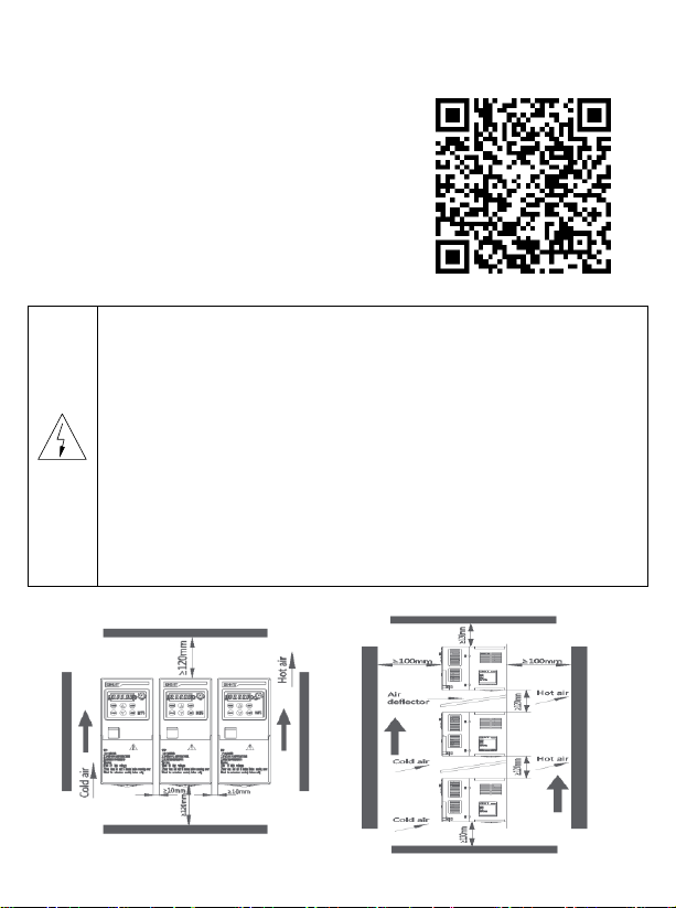
Installation Dimensions:
Figure 1-1 Figure 1-2
Page 2
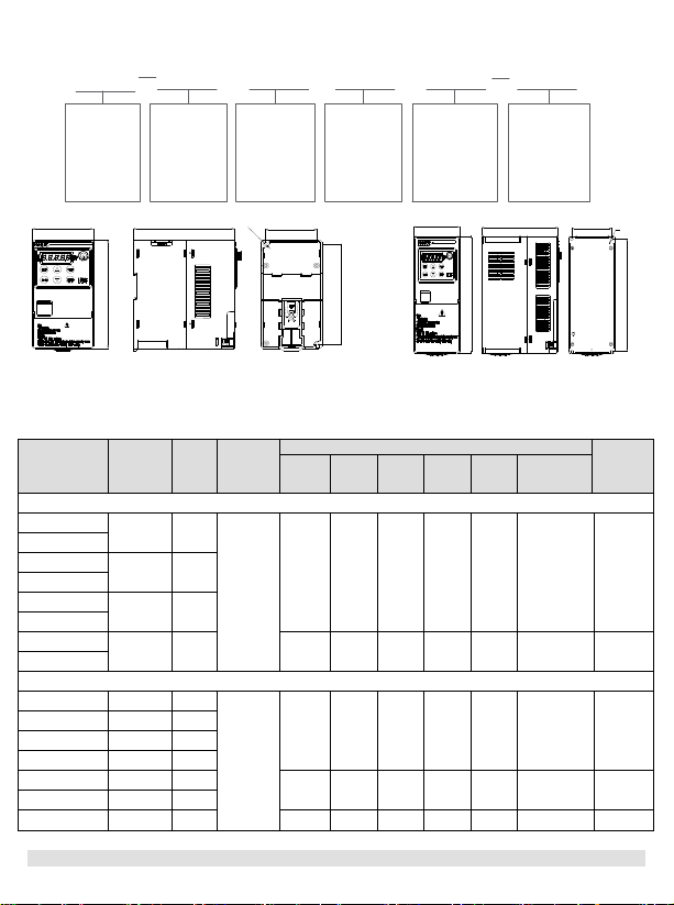
2.Catalog Number Description、Product Models、Dimensions and Weights
Applicable
Motor Power
(kW)
T: Universal
Model
Number of
Inverter Input
Phases
D: Single
Phase
S: Three
Phases
Input Voltage
Rating
2:230V
4:380V~ 440V
Brake Unit
B: Standard
Embedded
Blank: No
Embedded
NVF5 0.4 T D 2 B
Product
Model
/
W
H
D
H1
W1
d
W
H
D
W1
H1
d
Catalog No.
Adaptive
Motor
kW
Output
Current
A
Brake
Unit
Unit (mm)
Weight
kg
W H D
W1
H1
Mounting
Hole
d
Single Phase AC 230V
NVF5-0.4/TD2
0.4
2.5
Optional
(embedded)
75
148
125.2
64
137.5
Φ5.3
1.2
NVF5-0.4/TD2-B
NVF5-0.75/TD2
0.75
5
NVF5-0.75/TD2-B
NVF5-1.5/TD2
1.5
7.5
NVF5-1.5/TD2-B
NVF5-2.2/TD2
2.2
10
75
148
146.7
64
137.5
Φ5.3
1.25
NVF5-2.2/TD2-B
Three Phase AC 380V~440V
NVF5-0.4/TS4-B
0.4
1.5
Standard
(embedded)
75
148
125.2
64
137.5
Φ5.3
1.03
NVF5-0.75/TS4-B
0.75
2.7
NVF5-1.5/TS4-B
1.5
4.2
NVF5-2.2/TS4-B
2.2
5.8
NVF5-3.7/TS4-B
3.7
10.5
89.5
206
149.2
78.5
196.8
Φ5.5
1.79
NVF5-5.5/TS4-B
5.5
13
NVF5-7.5/TS4-B
7.5
17
118
216
163.4
105
205
Φ6
2.78
NVF5-0.4/TD2~NVF5-2.2/TD2、NVF5-0.4/TD2-B~ NVF5-3.7/TS4-B~NVF5-7.5/TS4-B
NVF5-2.2/TD2-B and NVF5-0.4/TS4-B~NVF5-2.2/TS4-B product appearance and installation
product appearance and installation dimension diagram dimension diagram
3.Installation and Wiring
3.1 Power Terminal Description
Figure 2-1 Figure 2-2
Page 3
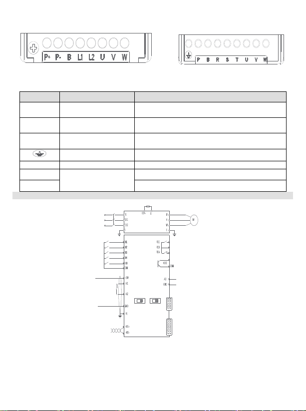
(1) Single Phase 230V(NVF5-0.4/TD2~2.2/TD2 (2) Three Phase380V(NVF5-0.4/TS4-B~
Terminal
Name
Description
R、S、T
Main Power Supply
Input
The three-phase AC input terminals ,connecting
with the power grid
L1、L2
Main Power Supply
Input
The Single-Phase AC input terminals ,connecting
with the power grid
U、V、W
Inverter Output
The three-phase AC output terminals ,connecting
with the AC motor
Grounding
Grounding terminals,ensure reliable grounding
P+ P-
DC Bus Terminals
Single phase type DC+ and DC-
P B
Outer Brake Resistor
Terminals
Three phase type brake resistor terminals
P+ B
Single phase type brake resistor terminals
V:(-10~10)V
I:(0~20)mA or (4~20)mA
RS485 communication
Three-phase input power
Brake resistor
Main circuit terminal
Control circuit terminal
QF
Power grounding
Motor grounding
A11
V1I1
2 x Analog input
Analog input power supply
Analog input common
230V 50/60Hz
AO
Programmable
Multifunction
AOVAOI
380V~440V 50/60Hz
Single-phase input poweer
V:(0~10)V
I:(0~20)mA or (4~20)mA
Analog output
Output
J2、J3 Multifunction extension card interface
J2 Multifunction interface
J3 Multifunction interface
Programmable relay outputs
Programmable open collector
Input
high-speed output
and NVF5-0.4/TD2-B~2.2/TD2-B) 7.5/TS4-B)
NVF5-0.4/TD2~2.2/TD2 and NVF5-0.4/TS4-B~7.5/TS4-B
NVF5-0.4/TD2-B~2.2/TD2-B Power Terminal Power Terminal
Figure 3-1 Figure 3-2
3.2 Power terminal and I/O terminal block diagram
AO Dip Switch:Left,( 0~20)mA or (4~20)mA Analog Current Ouput;Right,( 0~10)
V Analog Voltage Output.
AI1 Dip Swith:Left,( 0~20)mA or (4~20)mA Analog Current input;Right,( 0~10)VAnalog
Voltage input.
AI2:Current Output need to be customized.
Figure 3-3
Page 4
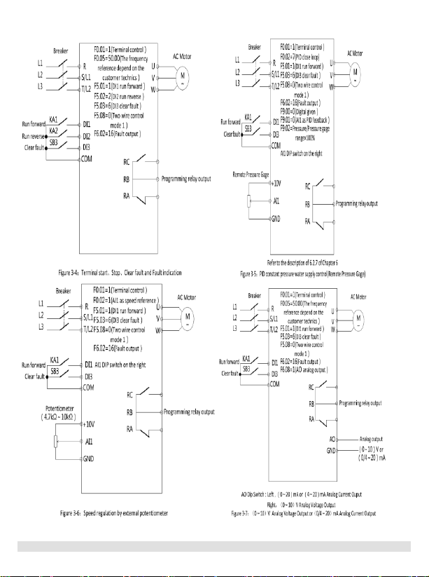
Wiring Demonstration:
4.Integral Keypad
4.1 Integral Keypad and Indicators
Page 5
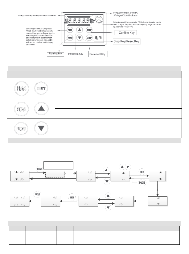
4.2 Combination key Function Description
Key
Description
+
Parameter Menu Mode Selection(F7.11)
1、 Simple Parameter Menu Mode(U-1)
2、 Custom Parameter Menu Mode(U-2)
3、 Engineering Parameter Menu Mode(U-3)
+
The system is under the main
interface
Lock Combinational Key
In custom menu mode,in menu level
one
Add custom parameters
+
The system is under the main
interface
Unlock Combinational Key
In custom menu mode,in next level
menu
Delete custom parameters
Ready status:
5.00Hz flash
F0 F0.05
2S
later
5.00F0.00
Parameters
10.00 5.00
5.00
F0.14
5.00
10.00
U-1
Change parameter
No.
using
Press
Press Shift
key
Press
Press
Press
Parameter menu
mode information
`
Press
Press
Press
Press
Press
Press
Press Shift
key
Code
Name
Attribute
Parameter Description
Default
F0.00
Motor Control
Mode
◎
0:Sensorless Vector Control
1:Reserve
2:V/F Mode
0
Figure 4-1
4.3 Parameter Menu Mode Demonstration
Simple parameter menu mode demonstration:
Below example is how to set parameter F0.05 from 5.00Hz to 10.00Hz in Simple Parameter
Menu Mode.
Figure 4-2 Simple Menu Mode Parameter Setting
5. Simple Parameter Menu and Commissioning Process
5.1 Simple Parameter Menu List
Page 6
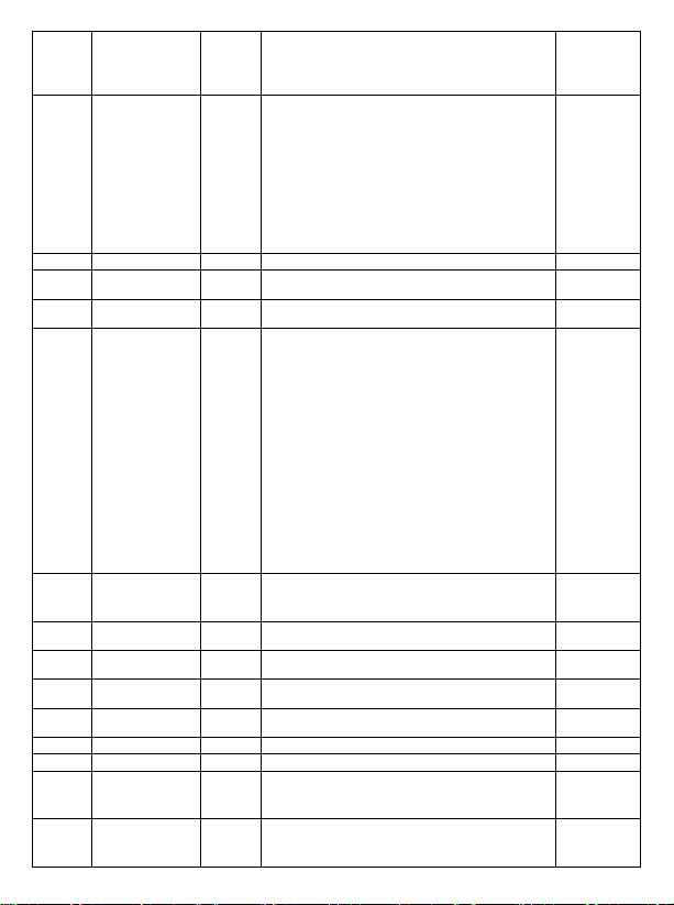
F0.01
Command
Source
○
0:Integral Keypad
1:Digital Terminal
2:Communication
3:Remote Panel
0
F0.02
Main
Frequency
Reference
○
0:Digital Given
1:AI1
2:AI2
3:Reserve
4:High Speed Pulse HDI Reference
5:Preset Speed Reference
6:Simple PLC Reference
7:Close Loop PID Reference
8:Reserve
9:Potentiometer Reference
0
F0.05
Digital Given
○
F0.09-Min. Frequency~F0.08-Max. Frequency
5.00Hz
F0.14
Accelerate
Time 1
○
(0.0~6500.0)s
Depend on
Series
F0.15
Decelerate
Time 1
○
(0.0~6500.0)s
Depend on
Series
F0.20
Parameter
Factory Default
◎
0:No Effect
1:Fault Log Clear
2: Set to Factory Default ( Except Motor NP
Parameters and Parameter F7.11)
3: Reset Custom Parameter Group to Factory
Default ( Except Motor NP Parameters and
Parameter F7.11)
4:All Parameter Reset to Factory Default
5:Back Up Parameters
6:Using Back Up Parameters
7:Saving Back Up Parameters
Note : Only when you are using backup
parameters,backup parameter are able to be
saved.Otherwise when power off then re-power
the inverter,except the updated parameters other
parameters are always initial value.
0
F2.00
Motor Type
○
0:AC Induction Motor
1:Reserve
2:Reserve
F2.01
Motor NP
Power
◎
(0.1 ~ 1000.0) kW
Depend on
motor type
F2.02
Motor NP
Voltage
◎
0V ~ Inverter Rated Voltage
Depend on
motor type
F2.03
Motor NP
Current
◎
(0.1~1000.0)A
Depend on
motor type
F2.04
Motor NP
Frequency
◎
0.01Hz ~ F0.07
Depend on
motor type
F2.05
Motor Poles
◎
2 ~ 24
4
F2.06
Motor NP RPM
◎
(0~60000)rpm
1430rpm
F2.22
Motor Auto
Tuning
◎
0:No Operation
1:Static Tune
2:Rotate Tune
0
F7.11
Parameter
Menu Mode
◎
1:Simple Menu Mode
2:Custom Menu Mode
3:Engineering Menu Mode
1
Page 7
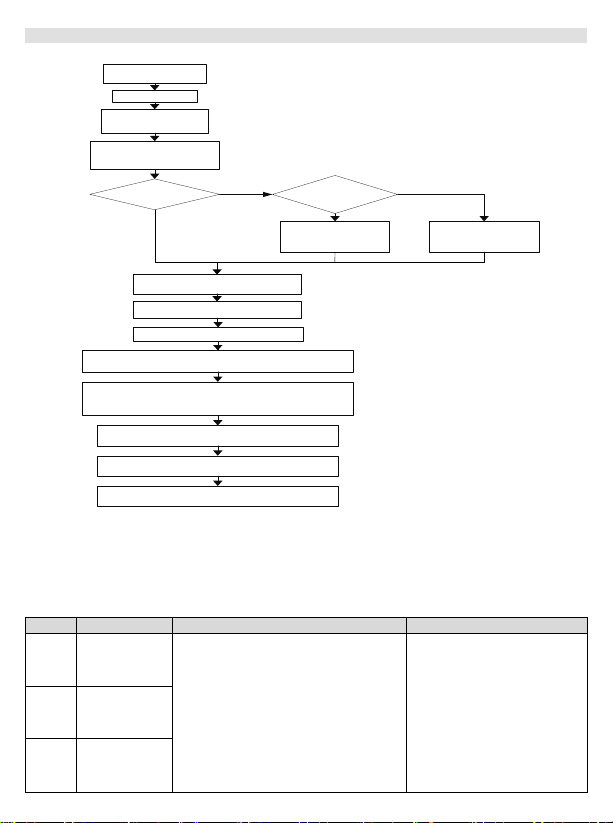
5.2 Simple Commissioning Process
Power on
Need motor
auto tuning
Confirm the main
circuit and control
circuit correct
Select motor
control mode by
parameter F0.00
Set parameter F2.22
to 1, press RUN key
to conduct static
motor auto tuning
Can disconnect
motor load?
Input the correct motor
nameplate data
Set parameter F2.22
to 2, press RUN key
to conduct rotate
motor auto tuning
Set reference frequency by
parameter F0.05
When the inverter is ready, press Run key to start
the motor without load, measure and check the 3-
phase current balance
After testing completed, stop the inverter, prepare
to set other parameters as equipment required
Input the correct motor nameplate
data in parameter group F2
(F2.01~F2.06)
Set NVF5 motor control mode according
to parameter F0.00 definition. The default
mode is V/F control.
After power on, the default 5.00Hz
will be displayed on NVF5 integral
keypad screen normally
Set Accel. and Decel. time
Set Accel.time and
Decel.time by parameter
F0.14 and F0.15
Default reference frequency is
5.00Hz. It can be changed as
required.
Yes
No
Refer to Chapter 3 -“Installation
and Wiring” for check correct
wiring
If the inverter is running normally without load, the
inverter can be tested with load, measure and
confirm the 3-phase current balance, and also
confirm the current less than rated motor current
The output current value of
inverter is almost the same as
the value displayed on
integral keypad of NVF5,
motor running direction refer
to parameter F0.06
After testing completed, stop the inverter
and set other parameters as required
Record the current value and parameters
Run the motor at 5.00Hz and
check the motor running direction
If the motor runs reverse,
change parameter F0.06 or
change the 3-phase motor
cables.
Yes
No
Code
Fault Type
Fault reason
Action
E.OC1
Inverter
Accel.
running
overcurrent
Low grid voltage
Directly and quickly start rotating motor
Incorrect Motor Nameplate
Too small inverter power
Unsuitable V / F curve
Potential Energy Load or Big Inertial Load
Accel./Decel. Time too short
Load Fast Change
Check the input power supply
Increase accel. time
Motor auto tuning
Enlarge inverter power rate
Adjust V/F cruve or adjust manual
torque boost
Add Regen. Brake Components
Check load
E.OC2
Inverter
Decel.
running
overcurrent
E.OC3
Inverter
constant
speed running
overcurrent
6. Fault description and Trouble shooting
If a fault appears,Please see for an explanation of the fault code and check by yourself firstly
before asking for help from Chint or Chint channels.When you need support,please contact
Chint or Chint channels.
Figure 5-1
Page 8
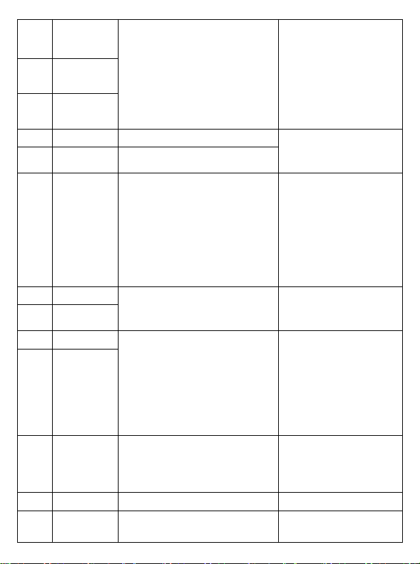
E.OV1
Inverter
Accel.
running
overvoltage
Motor short circuit to ground
Abnormal input voltage
Motor quick start again at high speed
Potential Energy Load or Big Inertial Load
Increase decel. time
Incorrect setting of Parameter ASR
in vector control
Big Inertial Load
Check motor cable
Check the input power supply
Start inverter when motor stop
Add Regen. Brake Components
Increase decel. time
Refer to Parameter Group F3
about how to set ASR
E.OV2
Inverter
Decel.
running
overvoltage
E.OV3
Inverter
constant
speed running
overvoltage
E.SPI
Input Lose
Phase
R.S.T lose phase
Checking Main Power Terminal
Wiring
Check Input Voltage
Check Motor Cable
Check Motor and Cable
E.SPO
Output Lose
Phase
U.V.W lose phase
E.FO
Power Module
Protection
The output three-phase with
interphase short circuit or ground
short circuit
Inverter instantaneous overcurrent
Fan duct blockage or fan damage
High ambient temperature
Loose I/O wiring or plug
Current waveform anomaly due to output
lose-phase and other reasons
Aux. power supply damage,
drive voltage undervoltage
IGBT Module Damage
Control Board Abnormal
Re-wire, confirm the motor
insulation
See overcurrent handling
Clear the fan duct or replace
the fan
Lower ambient temperature
Check wiring and re-wire
Checking wiring
Asking for Chint technical support
E.OH1
Heat Sink
Overheat
High ambient temperature
Fan duct blockage
Fan damage
IGBT abnormal
Temperature checking circuit error
Lower ambient temperature
Clear the fan duct
Replace the fan
Asking for Chint technical support
E.OH2
Rectifier Bridge
Overheat
E.OL1
Motor Overload
Incorrect Motor Overload Ratio
Motor Stall or load change frequently
Long time low speed ruuning with excessive
load
Low grid voltage
Unsuitable V / F curve
Incorrect Motor Nameplate
Excessive load
Excessive DC Brake
Accel. Time too short
Input correct motor overload ratio
Check motor load
Select Frequency conversion
motor
Check grid voltage
Adjust V/F cruve or adjust manual
torque boost
Motor auto tuning
Enlarge inverter power rate
Reduce DC brake
current, increase brake time
Increase accel. time
E.OL2
Inverter
Overload
E.tE
Auto Tuning
Set Wrong Motor Data
Reverse Auto Tuning is
prohibited in reverse running
Poor contact of motor
connecting cable
Auto Tuning Overtime
Set correct motor data
Disable Reverse
Check motor cable
Check Parameter F0.08
(Frequency Max.) whether is
samller than rated frequency
E.StG
Motor short
circuit to ground
Motor short circuit to ground
Check motor cable
E.LL
Load Loss Fault
Inverter Current is Smaller than the value of
Parameter FE.18
Check whether load loss or
parameter FE.17、FE.18、FE.19
parameter setting
 Loading...