

Page 1
R01 21/09/2005
Page 2

At CHINOOK
we have two key words: specialisation and
experience.
Air compressors are own only product.
All our engineering skills and nearly thirty
years of manufacturing experience and
specialization are dedicated exclusively toward
the production of a complete line of single and
two stage reciprocating compressors ranging
from 1/2 horsepower four cylinder two stage
models.
Our compressors are designed for the most
discriminating compressor buyer under the
most demanding operation conditions.
CHINOOK compressors are sold and
serviced throughout the world in all mayor
industrialized countries.
Our simple but reliable and proven design is
easy to maintain and service.
Replacement parts and service are available
throughout the world from authorized
distributors and service centers.
Page 3

Page 4
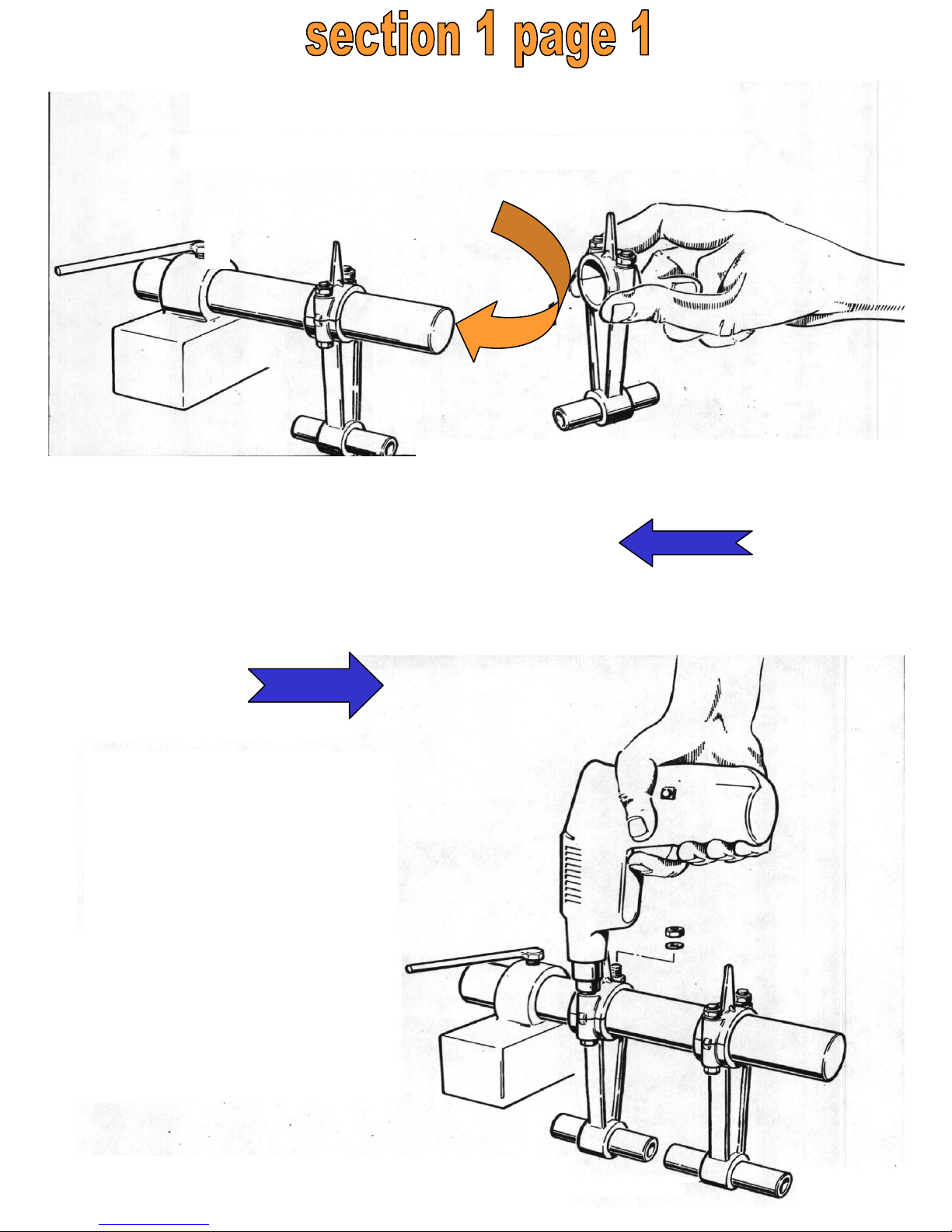
Insert the conrods with
their piston pin onto the tool.
1
Loosen the conrod nuts
by means of a pneumatic
screwdriver.
Remove the nuts and
washers (not to be used
again)from the conrod screws.
2
Page 5
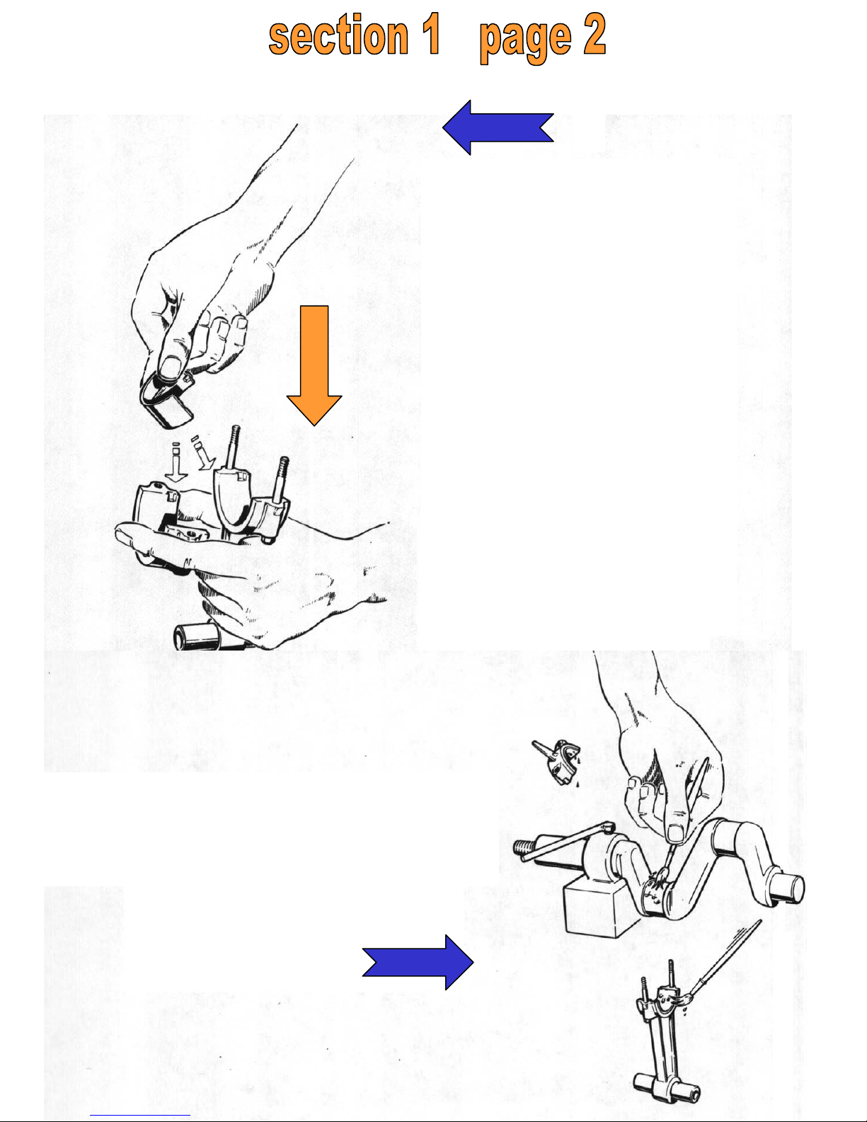
Pull out the conrod and
hold it as shown in the
drawing; insert the halfshells.
NOTE :
The conrod stem and
cap must be reassembled
the way they were and
not facing the other way.
Fit and oil the half-shells;
oil the conrod housing on the
crankshaft.
3
4
Page 6
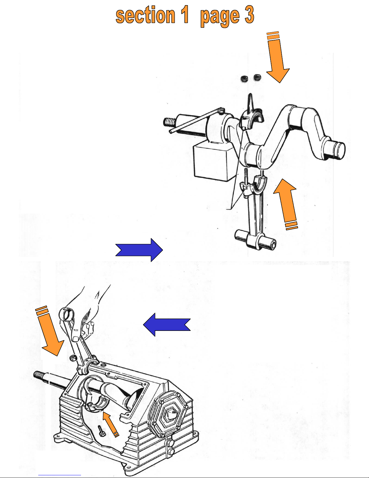
Position the conrod
stem and cap on the
conrod housing, on
the flywheel side,
making sure the locator marks on one
side of the stem and
cap are properly
matched.
Locator
marks
5
The position of the
conrod on the crankshaft must be as
shown in Table A,
which lists the screw
tightening torque
values.
6
Page 7
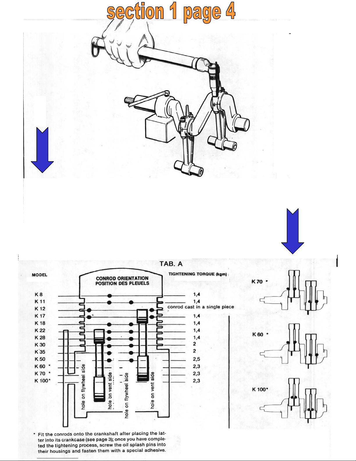
If necessary, tighten the nuts with a calibrated dynamometric
wrench, adjust conrod-crankshaft coupling with light hammer
blows. After that, tighten the nuts again with the dynamometric
wrench; the conrod must be able to rotate freely (see Table A).
Fit the conrods onto the crankshaft after placing the latter into its crankcase (see section 1 page 3); once
you have completed the tightening process, screw theoil spash pins into their housing and fasten them
with a special adhesive.
7
8
-K 9
Page 8

Page 9
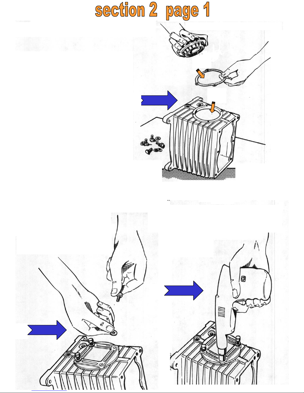
Fit the support on vent
side with a ball bearing
previously placed into its
support, with a support
gasket in between.
1
Fit the hexagonal
screw and the
aluminiumwasher.
Tighten the screws by means
of a pneumatic screwdriver.
2
3
Page 10
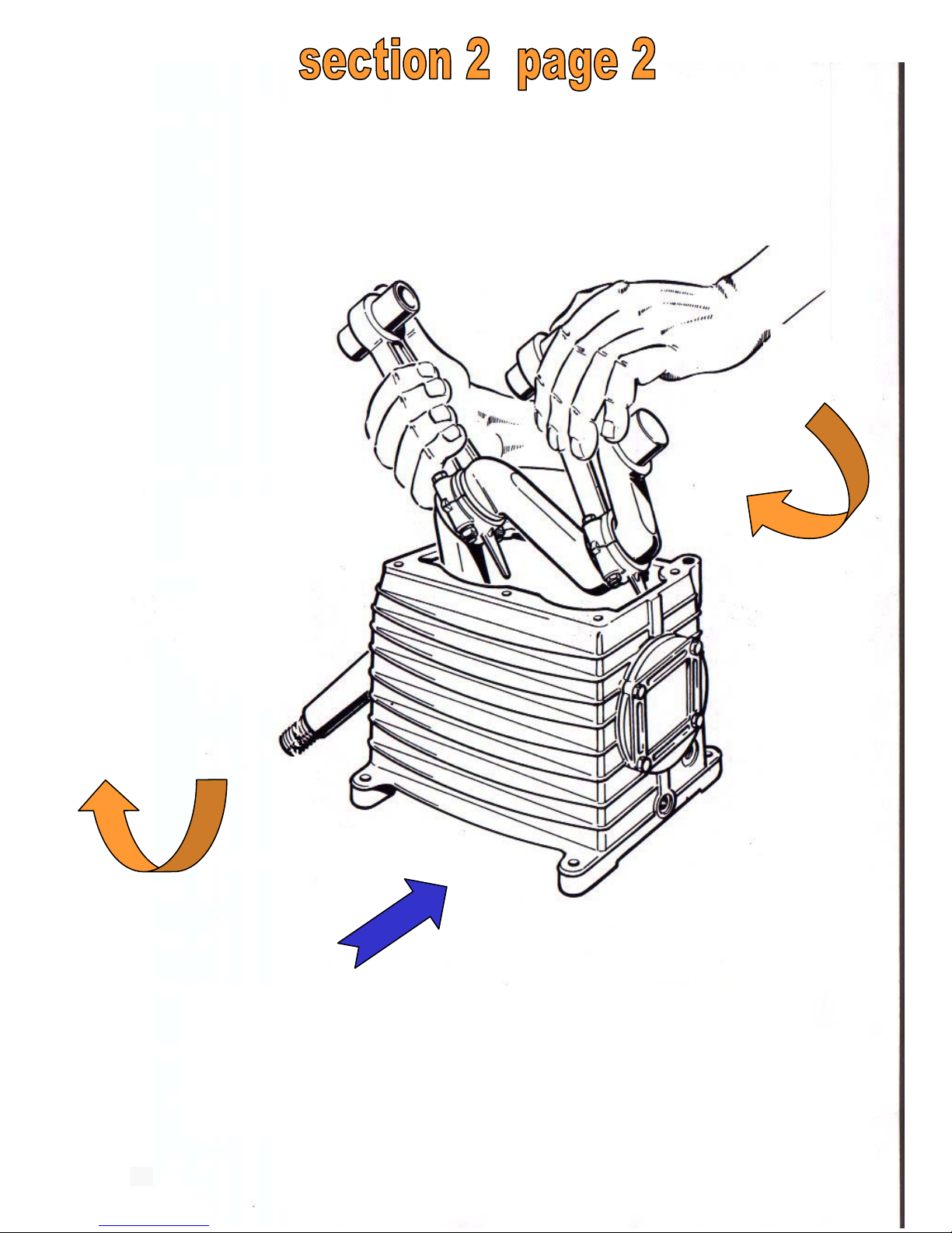
Put the crankshaft, with the conrods
mounted, into the crankcase.
4
Page 11
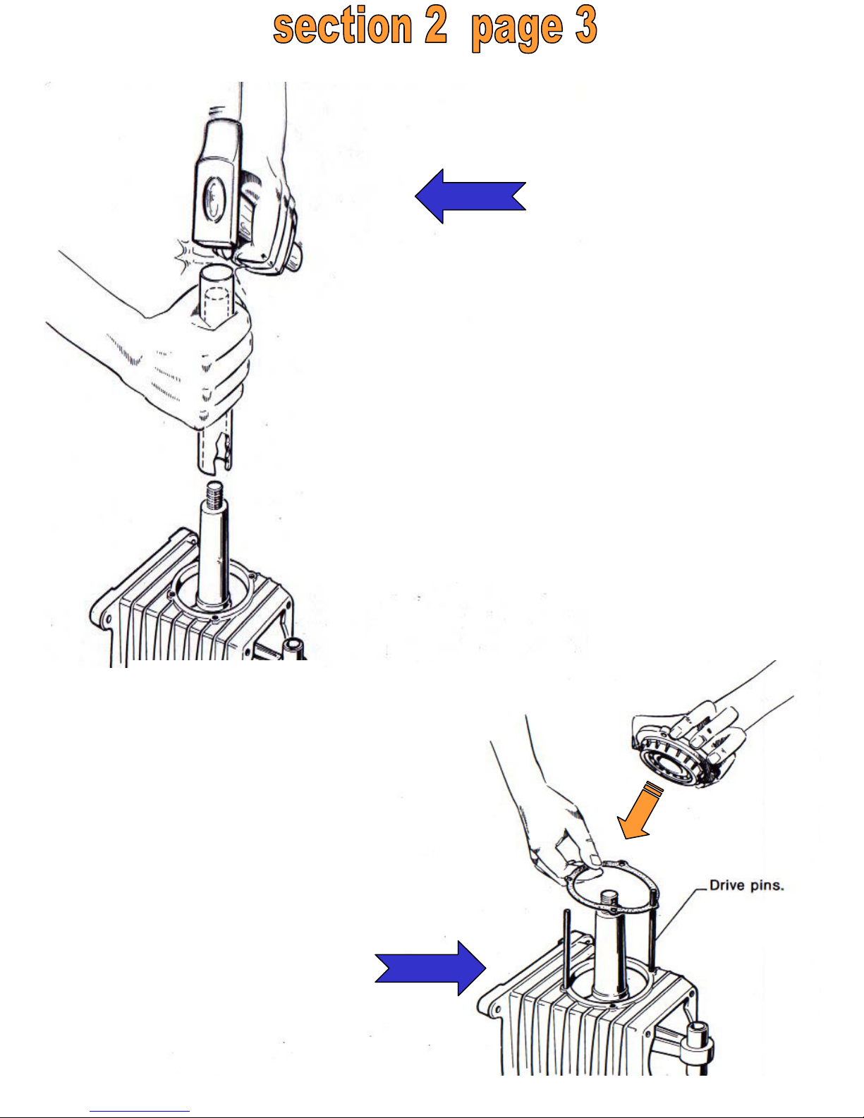
Put the crankshaft into the ball
bearing housing fitted to the
vent
support, by means of a special
punch.
Fit and tighten the guiding
pins before fitting the support
and the gasket.
Fit the support on flywheel side
with the ball bearing previously
assembled onto the support,
with the support gasket in
between.
5
6
Page 12
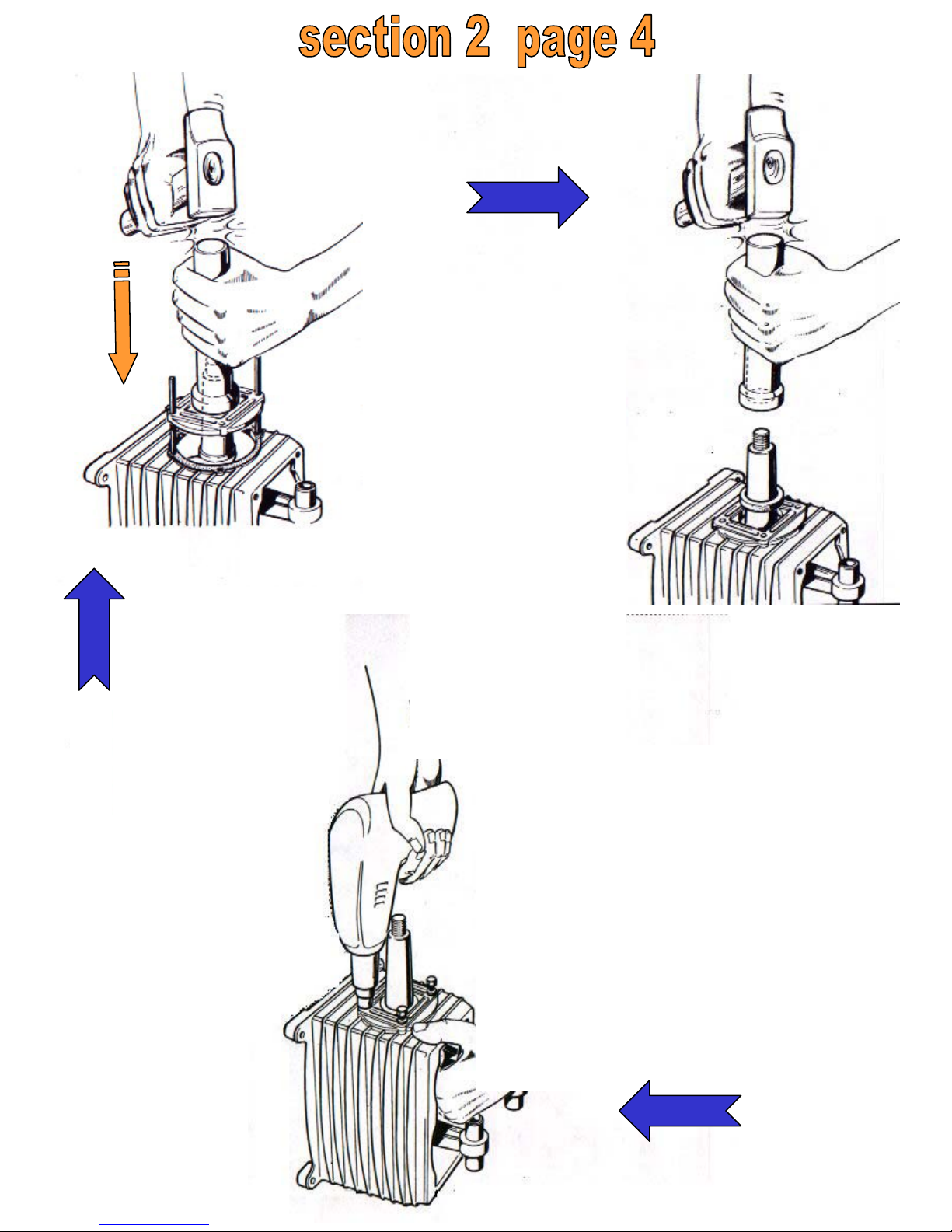
Place support
on
flywheel side
by
means of a
special
punch.
Place the
biangular
bearing
on the
support
housing by
means of a
special
punch.
Fix the hexagonal
screw
and aluminium
washer;
tighten the screws by
means of a pneumatic
screwdriver.
7
8
9
Page 13

Page 14
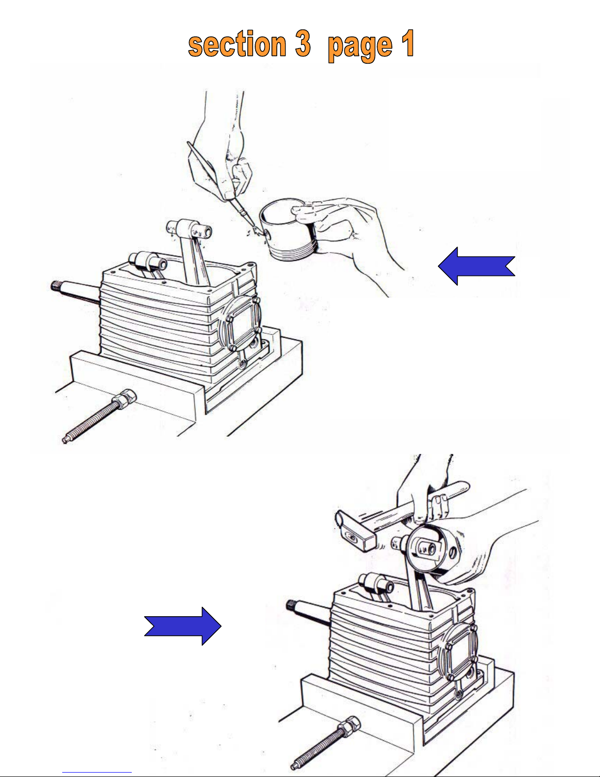
Put the crankcase in
a vice, oil the piston
pin and the piston pin
housing on the piston.
Fit the piston pin
half way onto
the piston.
1
2
Page 15
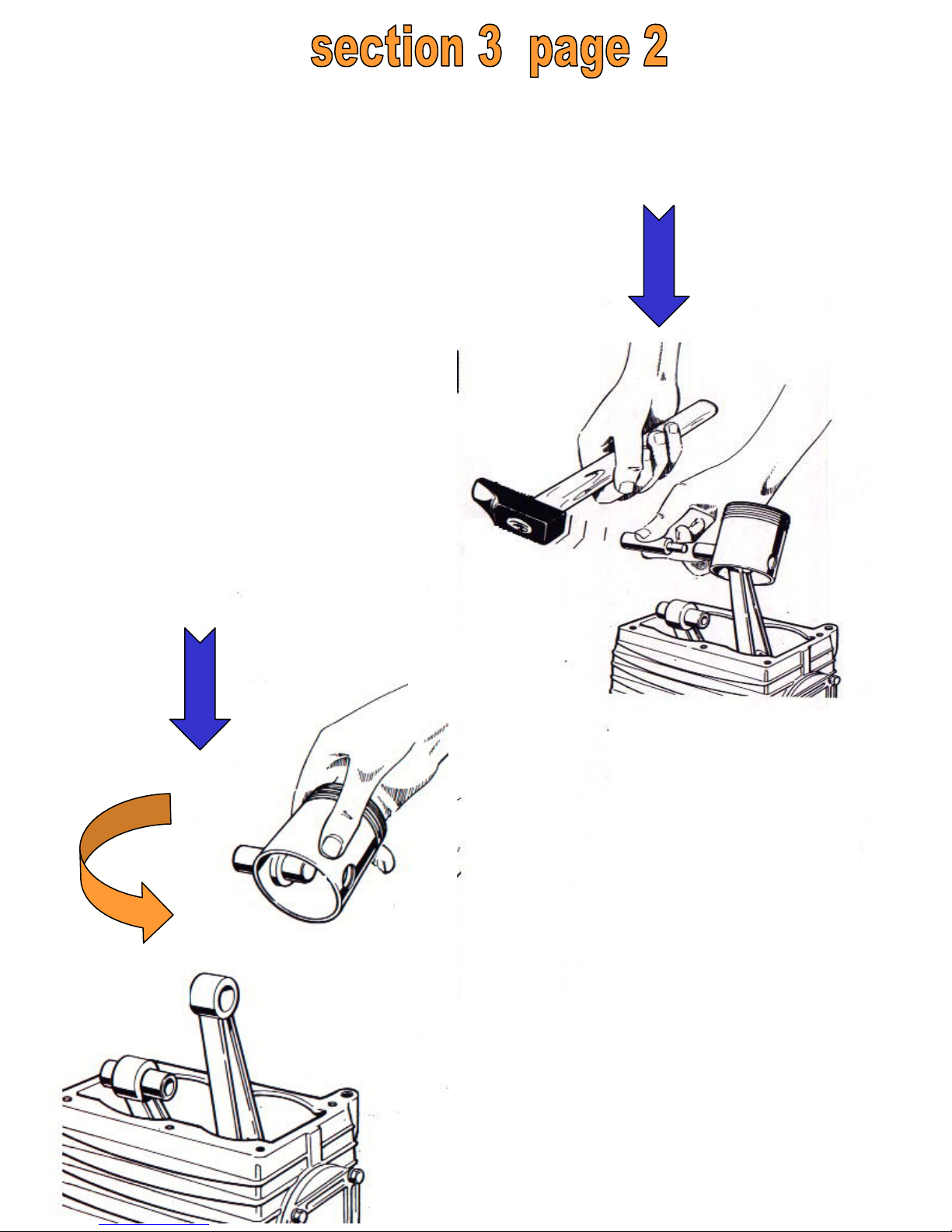
Pull out the piston with the
piston pin
partially fit in it from the
conrod.
Put the piston on the conrod
housing and drive the piston
pin.
Complete the
driving of the
piston pin by
means of a
special punch.
3
4
Page 16
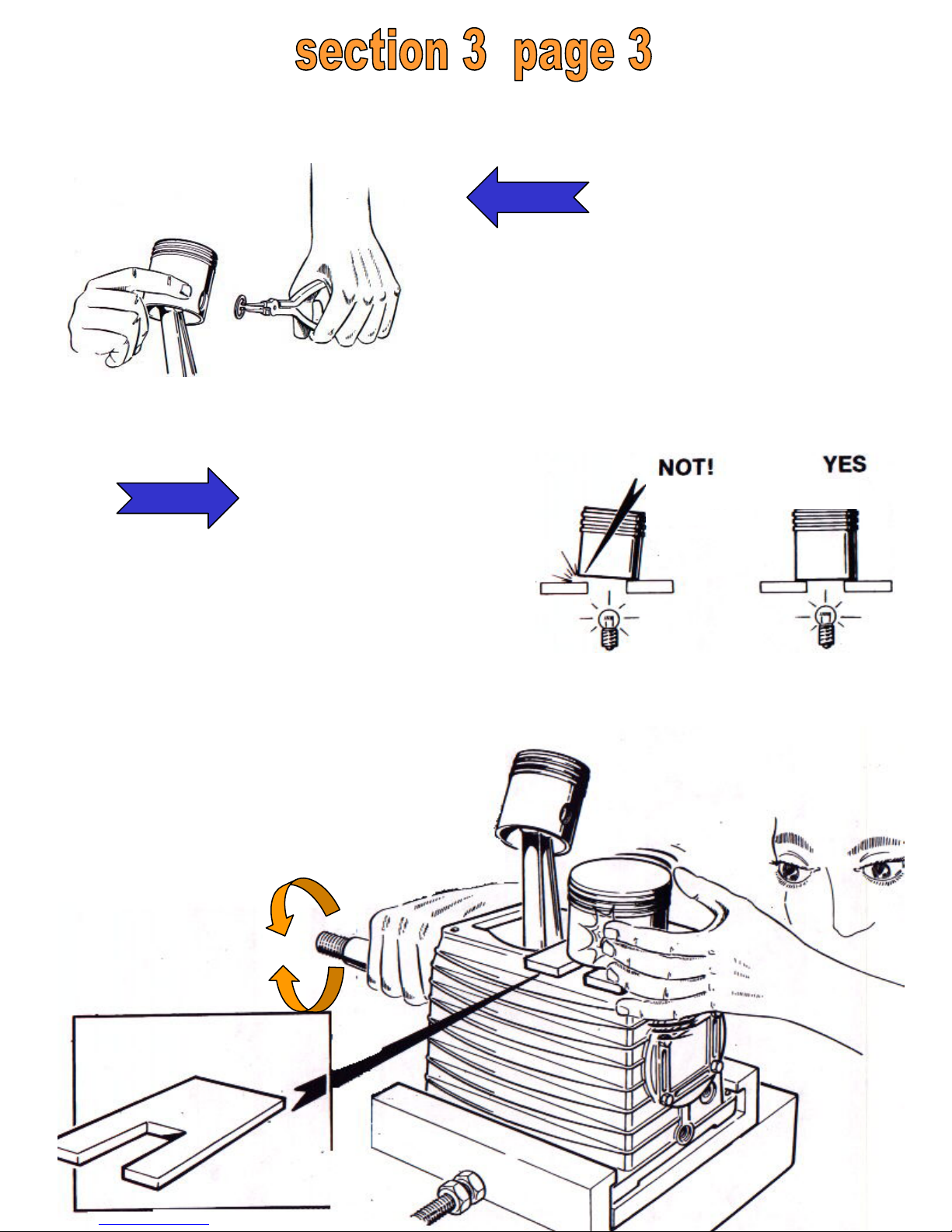
Place the reating
rings by
means of special
pliers.
5
Level the pistons with theaid
of a special faceplate.
This is done by slightly
Fitting the piston with the
palm of
your hand until the piston
base is perfectly
parallel to the faceplate.
6
Page 17
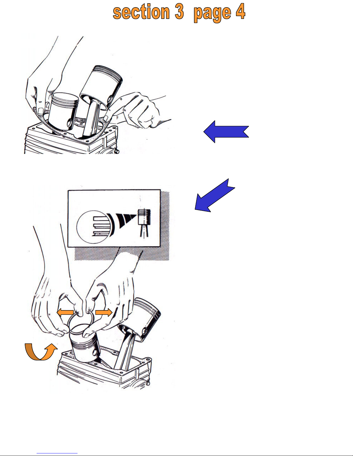
Fit the crankcase/cylinder
gasket.
7
8
Fit the piston rings.
Warning: the rings
must be placed with
the “Top” mark facing
up (towards the piston
crown).
The exacte position is
shown in the figure.
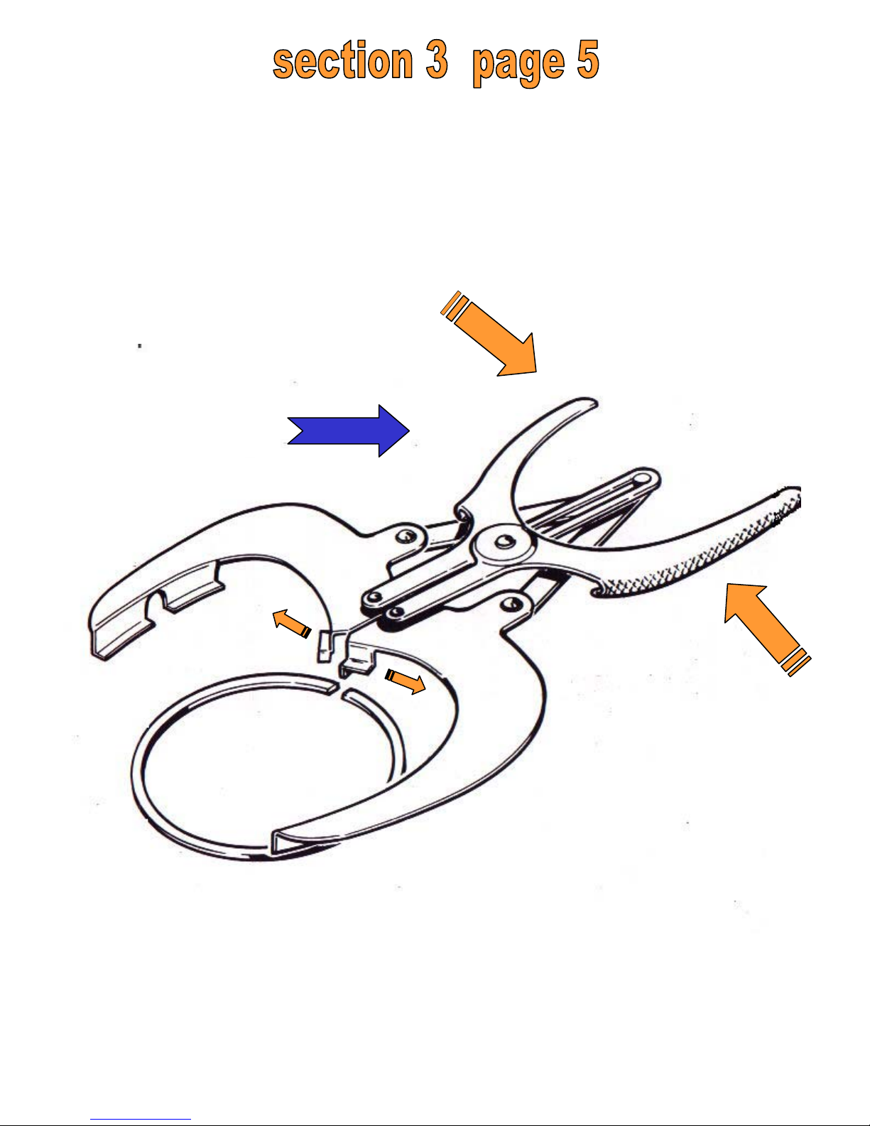
NOTE: In order to fit and change the piston rings
you can use the special pliers shown on
section 3 page 5.
Page 18
9
Special pliers
Page 19

Page 20
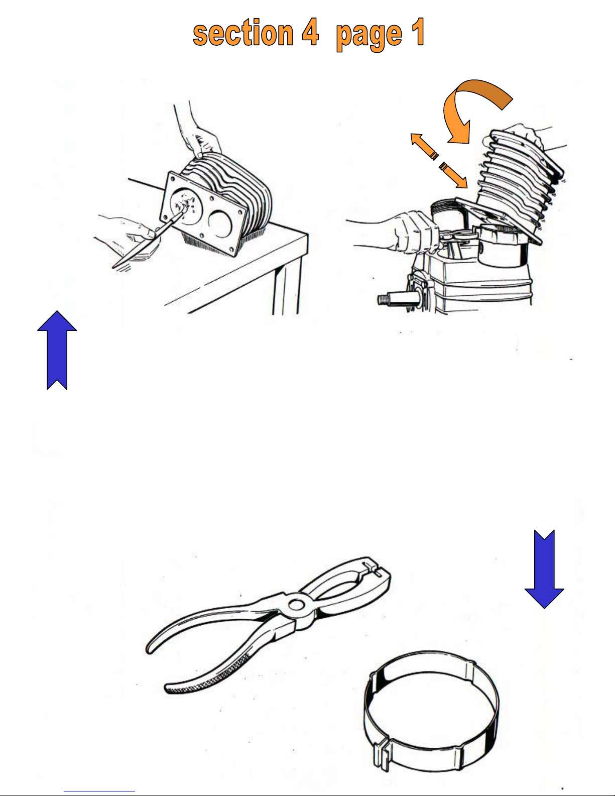
Oil the inner side of the cylinder
in which the pistons will be placed.
Tighten the rings onto the piston by means of a special pliers with a steel
band; insert the cylinder onto the piston.
Use the special tools
shown in the figure.
1
2
Page 21
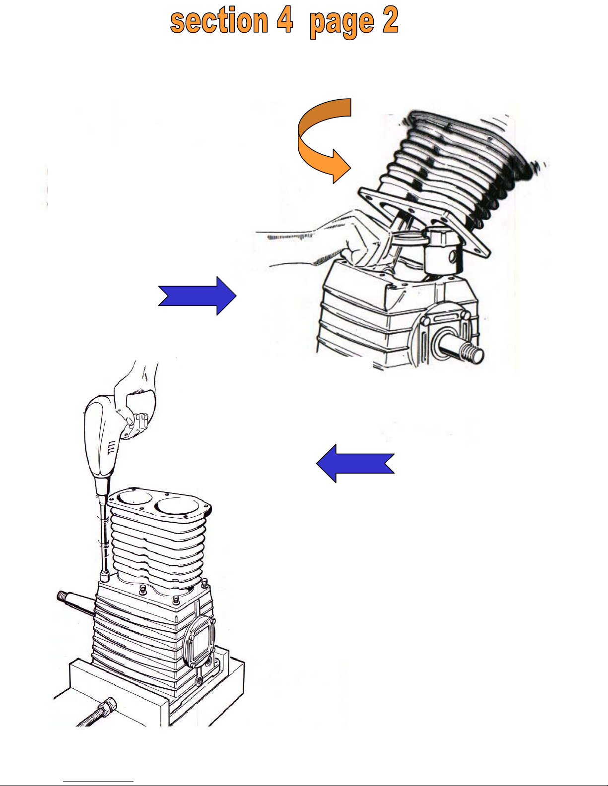
Repeat the foregoingstep
and place the cylinder
onto the second piston.
Fix the
hexagonal screw
and the
aluminium
washer using a
pneumatic
screwdriver.
3
4
Page 22
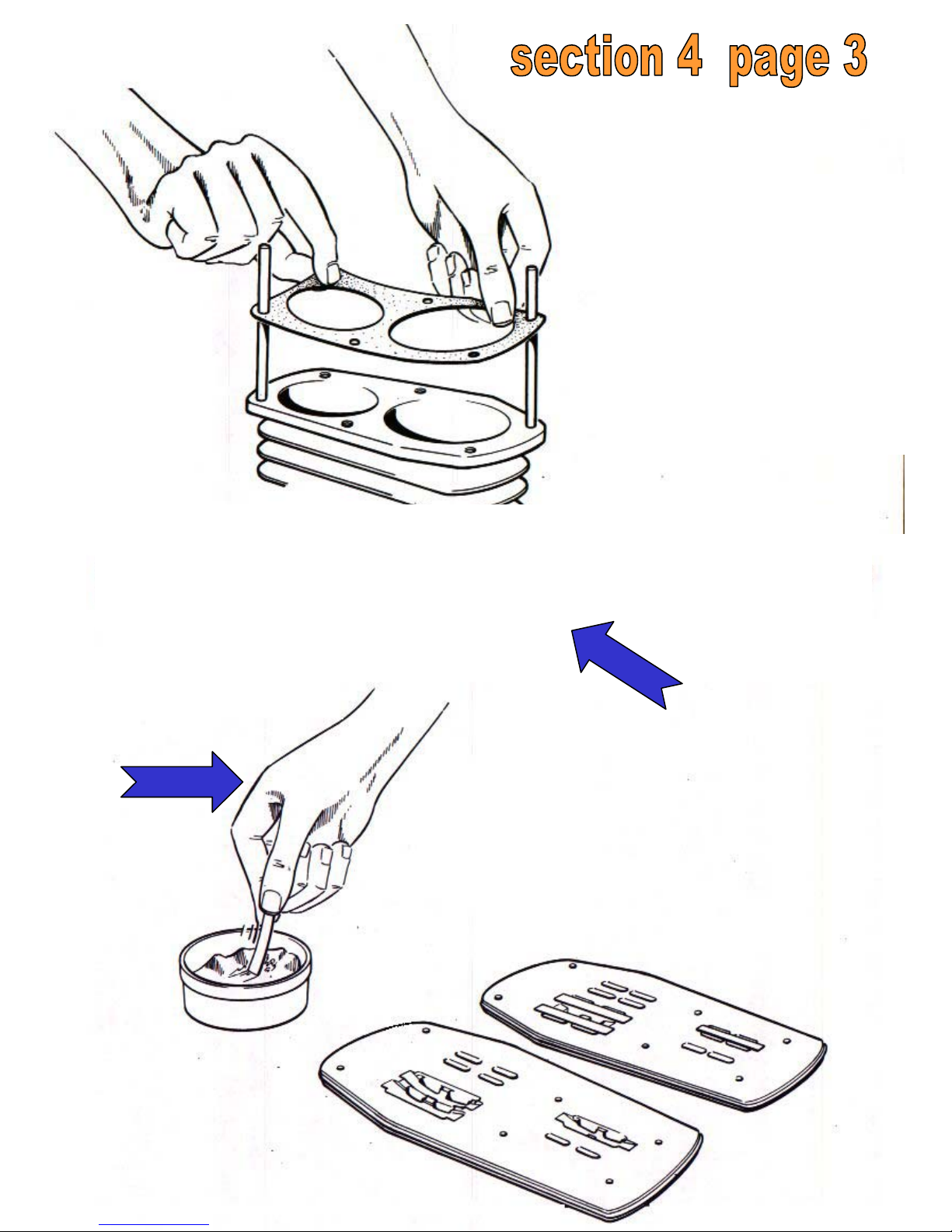
Place the
guiding pins
onto the
cylinder and
fit the
cylinder/plate
gasket.
Spread a small amount of vaseline onto the end of the
strip valves and fit them into the special housing built
in the valve plates.
6
5
Page 23
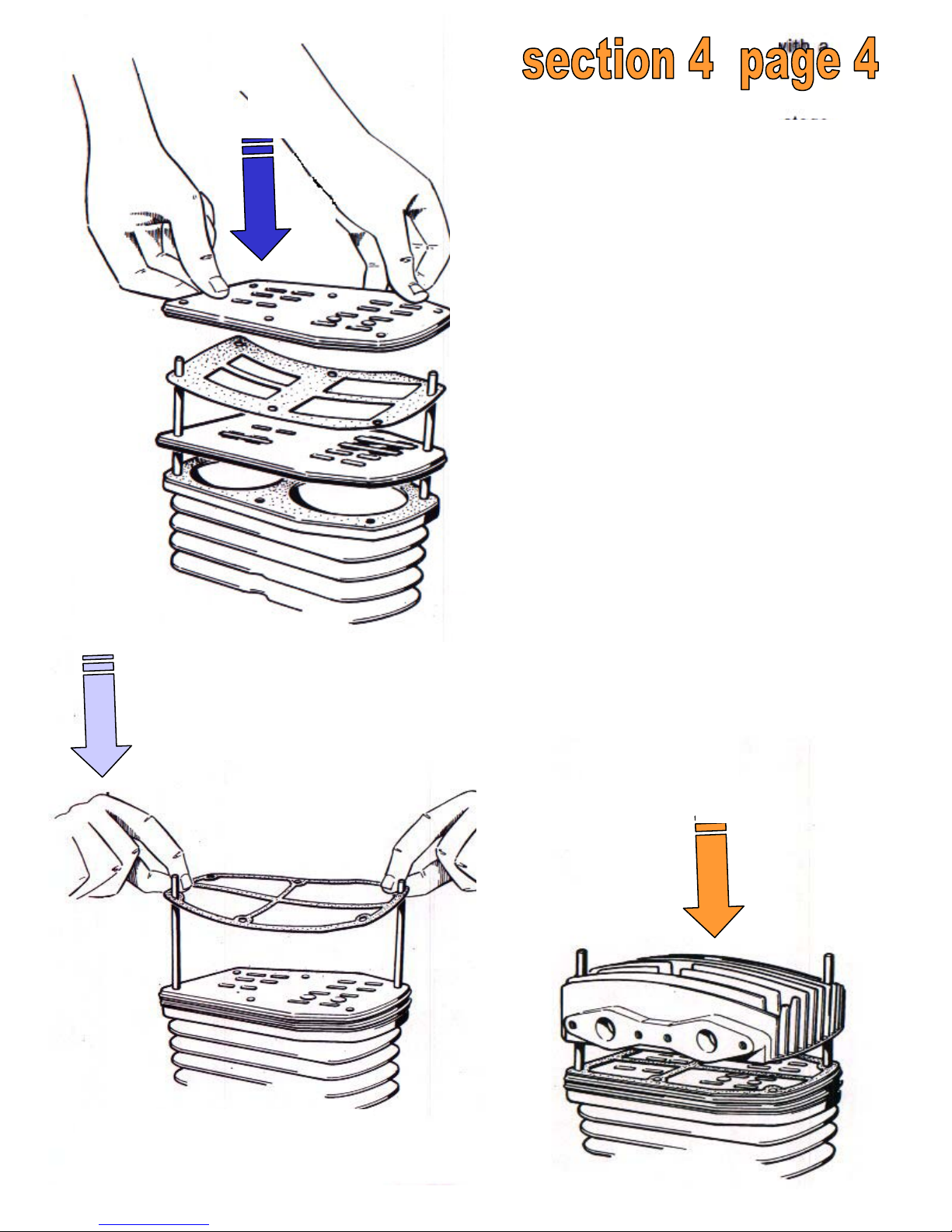
Fit the two valve plates
with a special gasket inbetween.
NOTE : The valve plates
of twostage compressors
can be assembled in one
position only. In the case
of single-stage
compressors, instead, it is
possible to
invert the compression
side with the intake side by
rotating the plate
at 180 °.
Fit the plate/head gasket.
Fit the head.
7
8
9
Page 24
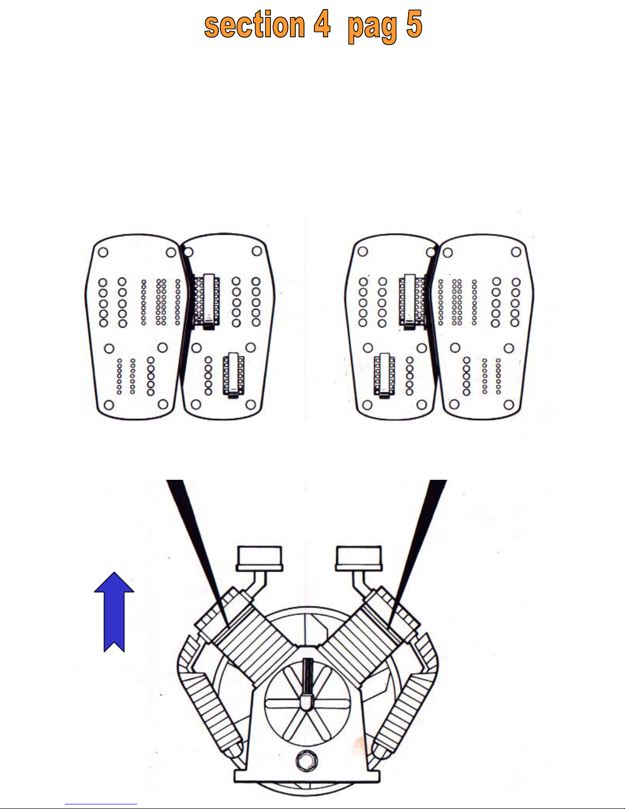
FLYWHEEL SIDE FLYWHEEL SIDE
VENT SIDE SIGHT
VENT SIDE VENT SIDE
All single-stage pumps in our range make it possible to position
the intake on either side, as desired, by simply rotating the plates
and head. The most important two-stage models are available
with special plates affording the same possibilities.
V type models are supplied with a special set of plates (called
“contrary” set). Its correct position is shown in the figure.
10
Page 25
SCREWS/HEAD Kgm.
TIGHTENING TORQUE
K 8 1.7
K 11 2.8
K 12 2.8
K 17 2.8
K 18 2.8
K 24 2.8
K 30 4
K 35 4
K 50 8
K 60 4
K 70 4
K 100 8
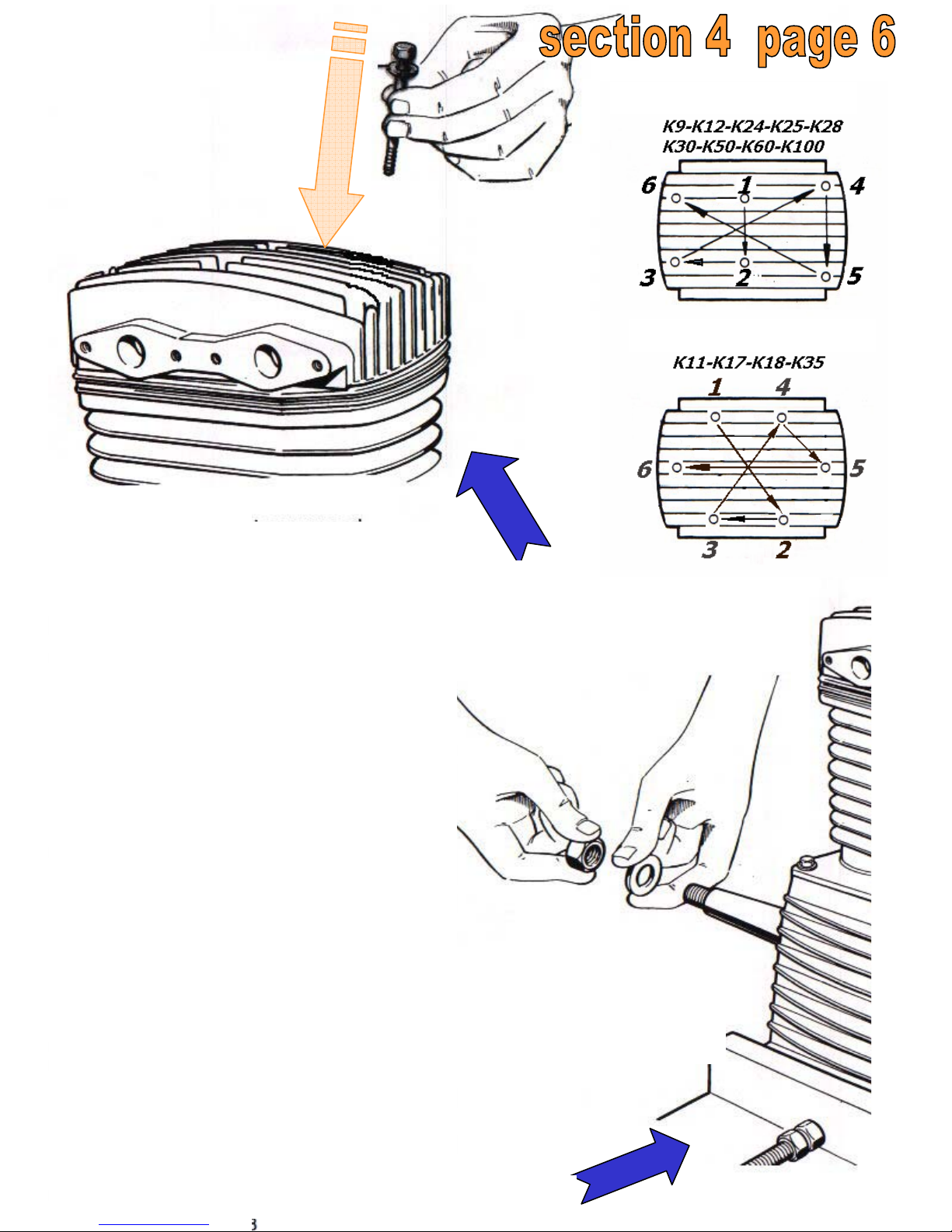
Place the
hexagonal
screws and steel
washers; fit lightly the
screws to the head
and then drive
them
according
to the
sequence
shown in
the figure
.
Place the flywheel,
and the flywheel
washer, and finally the
nut.
11
12
TIGHTEN
SCREW
HEAD
Kgm.
K 8 1.7
K 9 2,9
K 11 2.9
K 12 2.9
K 17 2.9
K 18 2.9
K 24 2.9
K 30 4,5
K 35 4,5
K 50 8
K 60 4,5
K 70 4,5
K 100 8
TIGHTENING
TORQUE
FLYWHEEL
NUT
Kgm.
K 8 3÷3,5
K 9 2,6/2,8÷3
K 11 3÷3,5
K 12 2,6/2,8÷3
K 17 4÷4,5
K 18 4÷4,5
K 24 4,5÷5
K 30 5,5÷6
K 35 5,5÷6
K 50 7÷7,5
K 60 7÷7,5
K 70 7÷7,5
K 100 8÷8,5
Page 26
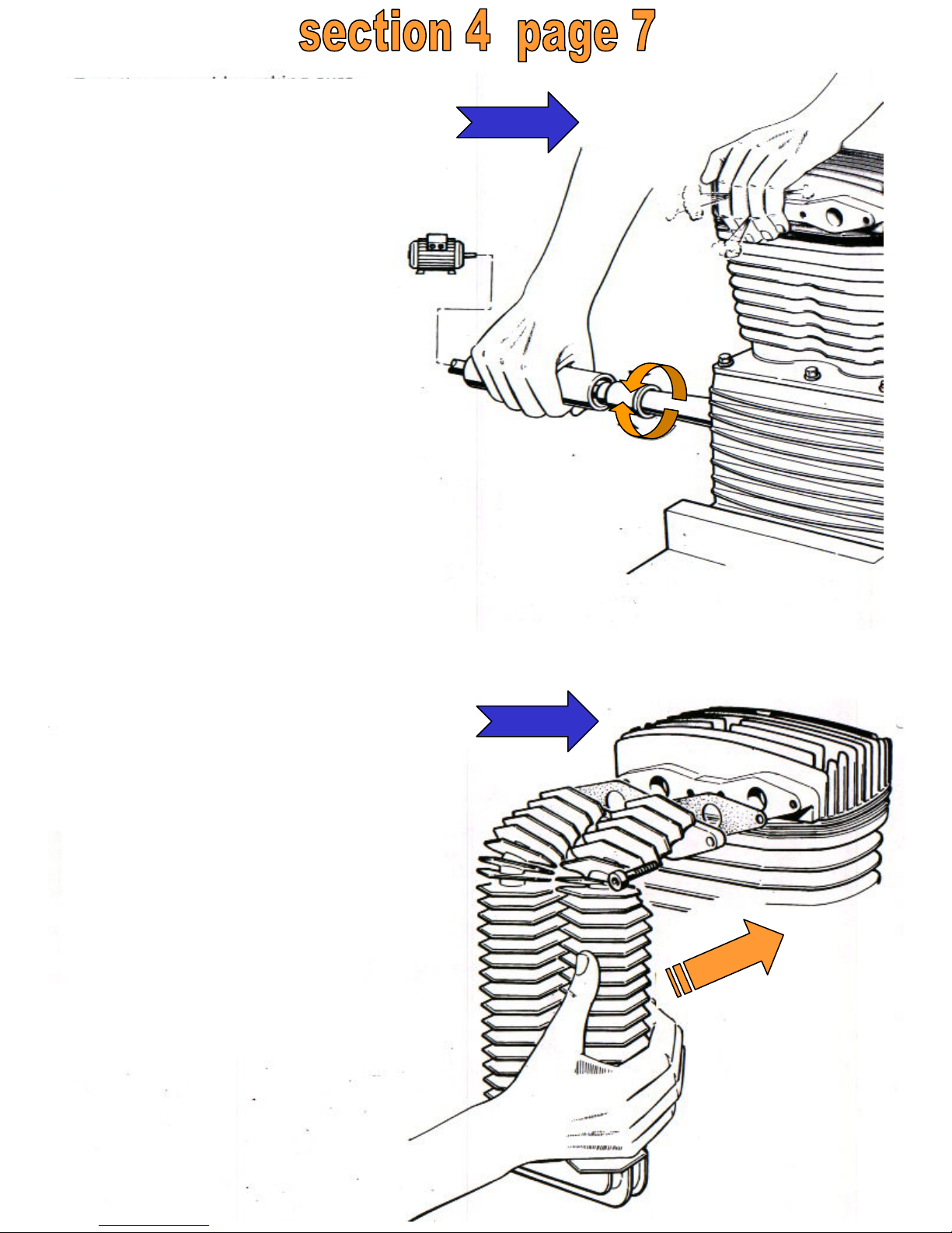
Test the assembly
making sure that
the intake and
compression stages
are
working
properly.
NOTE : To this end you can
make
use of a special tool, i.e. a
geared motor which
transmits the motion to the
crankshaft. If desired, the
assembly can be tested by
applying a suitable wrench to
the nut and rotating it by
hand. Fit the double cooler to
connect the 1st and 2nd
stage, with a cooler gasket in
between.
13
14
Page 27
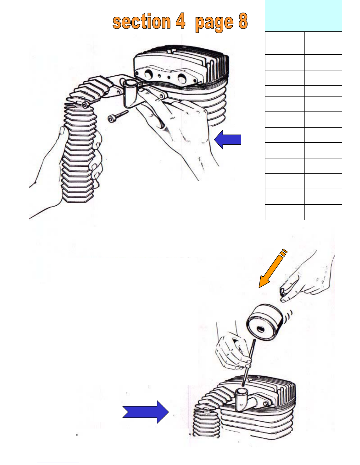
Fit the aftercooler with a
gasket in
between; fit the filter elbow
onto
its housing.
Assembly the filter
onto the
elbow. The filter is fit
on the
tension rod tightened
with the
aid of a special finned
nut.
15
16
4K 100
4K 60
4K 50
4K 35
4K 30
4K 24
4K 18
4K 17
4K 12-K 9
4K 11
4K 8
Tightening
KGMGROUP
(HEAD-COOLER BOLTS)
TIGHTENING COOLER BOLT
Ø10 mm
Page 28

Page 29
m
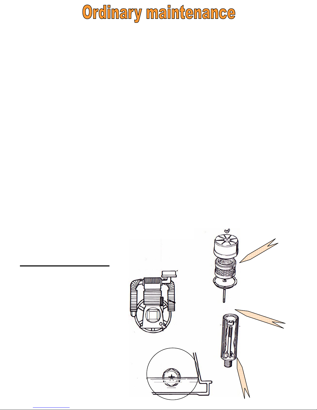
CLEANING THE OIL BREATHER
Wash the cap tank at regular intervals with fuel oil,
kero-sene or similar products so as to ensure that the
oil will flow back through the recovery inlet.
CHANGING THE FILTER CARTRIDGE
After about 400 hours of work in standard
environmental conditions.
CHECKING THE OIL LEVEL
The oil level must be maintened, by topping it up, as
close as possible to the centre of the oil window. Larger
quantities of oil might result in too much oil flowing out
from the oil breather, whilst lower quantities might
result an insufficient lubrification of the moving parts.
After 1.000 hours of work the oil has to be replaced.
We re-commend using oil type :
§ Q8 Haydn 100 for single phase machines with less than 2.2
kW (3HP).
§ Q8 Haydn 150 for three phase machines with more than
2.2 kW (3HP).
In temperatures of below +5°C only use SAE 20 oil. For
temperatures of
over +35°C only use SAE 40 oil.
or a similar product producing low carbon residues.
Oil capacity lt.
K 8 0,400
K 9 0,500
K 11 0,500
K 12 0,500
K 17 1,000
K 18 1,000
K 22 1,800
K 23 1,800
K 24 1,800
K 25 1,800
K 30 1,450
K 35 1,450
K 50 1,750
K 60 3,000
K 70 3,000
K 100 4,000
Page 30
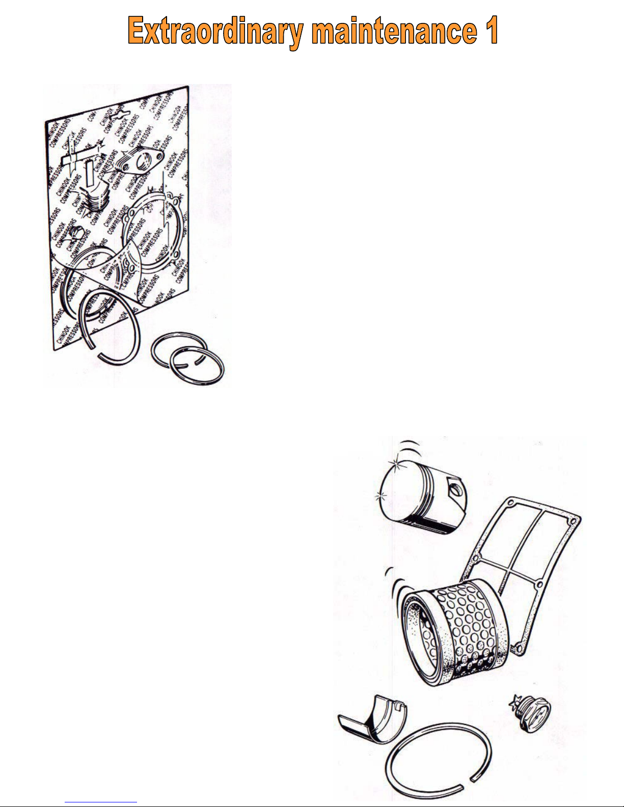
It consists in 3 stages for increasing
complexity.
For the first stage we supply the 1st
maintenance kit necessary to
replace
the materials for the filter
cartridge,
the strip valves and the
corresponding
gaskets.
The 2nd kit includes all the
materials contained in the 1st,
as well as piston rings, oil sight
gauges and caps.
The 3rd kit allows for more extensive repairs such as the replacement of the conrod shells
on the crankshaft, the piston pin
housing, bushing and the piston
pin. It also includes all the materials contained in the 2nd kit.
Page 31
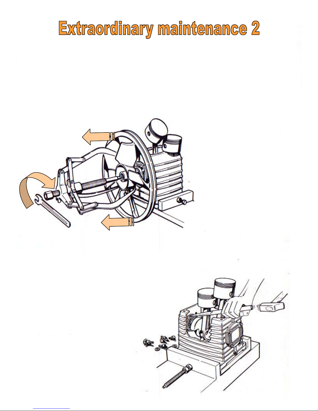
The drawing one
shows an ejector, the
indispensable tool for
pulling the flywheel
from the crankshaft
easily.
Whenever it is necessary to disassemble the pump in its entirety,
clean each individual piece and fit the new gaskets supplied with
the kit.
During the assembly operations, make sure that the valve plates, the head and the cylinder are levelled and are correctly
matched with one another.
The drawing two illustrates a practical
way to free the crankshaft from its
support. This must be done
in order to overhaul both the crankshaft
and the conrods.
The support and ball bearings could be
damaged in this process, fit new ones.
DRAWING 1
DRAWING 2
Page 32

Page 33

Defects Reduced efficiency of the compressor unit.
Cause Failure of strips valves • Broken gaskets • Obstructing material
in the valve plate air holes and/or in the strip valves themselves.
Remedy Take down the assembly and eliminate the cause of the defect • During
reassembly, make sure the lower piston plane is properly aligned with the
upper plain of the crankcase (see section 3- page 3).
______________________________________________________________________________________
Defect Noise, striking and rolling sounds caming from inside the crankcase which
may be ascribed to the moving parts (crankshaft, conrods, pistons, bearings).
Cause Insufficent lubrification. Coupling tolerances not suitable.
Remedy Identify the cause and eliminate the problem by replacing the defective parts.
______________________________________________________________________________________
Defect Oil flowing out from the oil breather, possibly in the form of vapour.
Cause Excessive quantity of oil.
Remedy Make sure the oil level is at below the center of the window.
______________________________________________________________________________________
Defect Excessive oil consumption.
Cause Piston ring worn out.
Remedy Fit new rings:
NOTE : If the machine is new, wait till the end of the running-in period
(approx. 100 h), then check again.
______________________________________________________________________________________
Page 34

Defect Exceedingly high temperature.
Cause Incorrect flywheel rotation due to incorrect electrical connections.
Poor ventilation of the room housing the unit.
Remedy Check flywheel rotation. Position the compressor at no less than
30 cm. from the wall. Air the room.
_______________________________________________________________________________
Defect Carbon residues on the plates.
Cause Oil not suitable or excessive heating.
Remedy Remove the oil, wash thorougly and fill with fresh AGIP DICREA
150 oil.
NOTE: Synthetic and mineral oils should not be mixed in any
circumstance.
Defect Water in the head.
Cause Critical conditions with high humidity contents. Incorrect slant of air
duct lines.
Remedy Fit a pipe to take in the air form a “standard” humidity environment.
Make sure that the condensate in the piping flows towards a special
discharge valve.
_______________________________________________________________________________
 Loading...