

China Electric Manufacture HH R001 User Manual
OPERATION INSTRUCTION
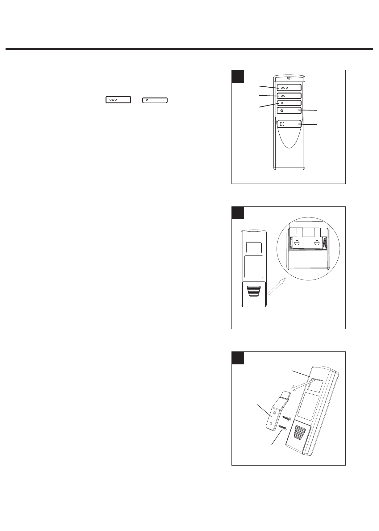
1. Pairing:
Within 30 seconds after power on,
press and hold Button & at the
same time for 5 seconds. LED indicator will flash .
When the pairing is done, it is shown that fan in LOW
and light is OFF.
2.Fan 3 speeds:
Tap key ①/②/③(See Fig.1) to control fan
high/medium/low speed.
3.Fan on/off :
Tap Fan on/off key(See Fig.1-④) to control fan on/off.
4.Light on/off:
Tap light key (See Fig.1-⑤) to control lignt on/off .
5.Light Delay Off Feature:
Press and hold fan off key(See Fig.1-④) for 5 seconds
to enter Light Delay Off mode. The light will be shut off
after 1 min.
To exit the Light Delay Off Mode, just tap the light key.
1
2
①
②
③
④
⑤
Fro nt
12V
.Power
6 Off Memory :
When power is off and back again, resume the status of
both light and fan before switch off.
Install the transmitter wall bracket in wall by
two screws and hang transmitter in it carefully.
(See fig.3)
Open the battery housing
cover and install a 12V
battery (included)inside.
Bac k
3
Transmitter
Wall Bracket
Screw
INSTALL AND MAKE WIRE CONNECTION
This device complies with part 15 of the FCC Rules. Operation is subject to the following two conditions:
(1) this device may not cause harmful interference, and
(2) this device must accept any interference received,
including interference that may cause undesired operation.
NOTE:
Changes or Modifications not expressly approved by the party responsible could void the user’s
authority to operate this device.
This equipment has been tested and found to comply with the limits for a Class B digital device,
pursuant to Part 15 of the FCC Rules. These limits are designed to provide reasonable protection
against harmful interference in a residential installation. This equipment generates,
uses and can radiate radio frequency energy and, if not installed and used in accordance with
the instructions, may cause harmful interference to radio communications. However, there is no
guarantee that interference will not occur in a particular installation.
If this equipment does cause harmful interference to radio or television reception, which can be
determined by turning the equipment off and on, the user is encouraged to try to correct the
interference by one or more of the following measures:
-- Reorient or relocate the receiving antenna.
-- Increase the separation between the equipment and receiver.
-- Connect the equipment into an outlet on a circuit different from that to which the receiver
is connected.
-- Consult the dealer or an experienced radio/TV technician for help.
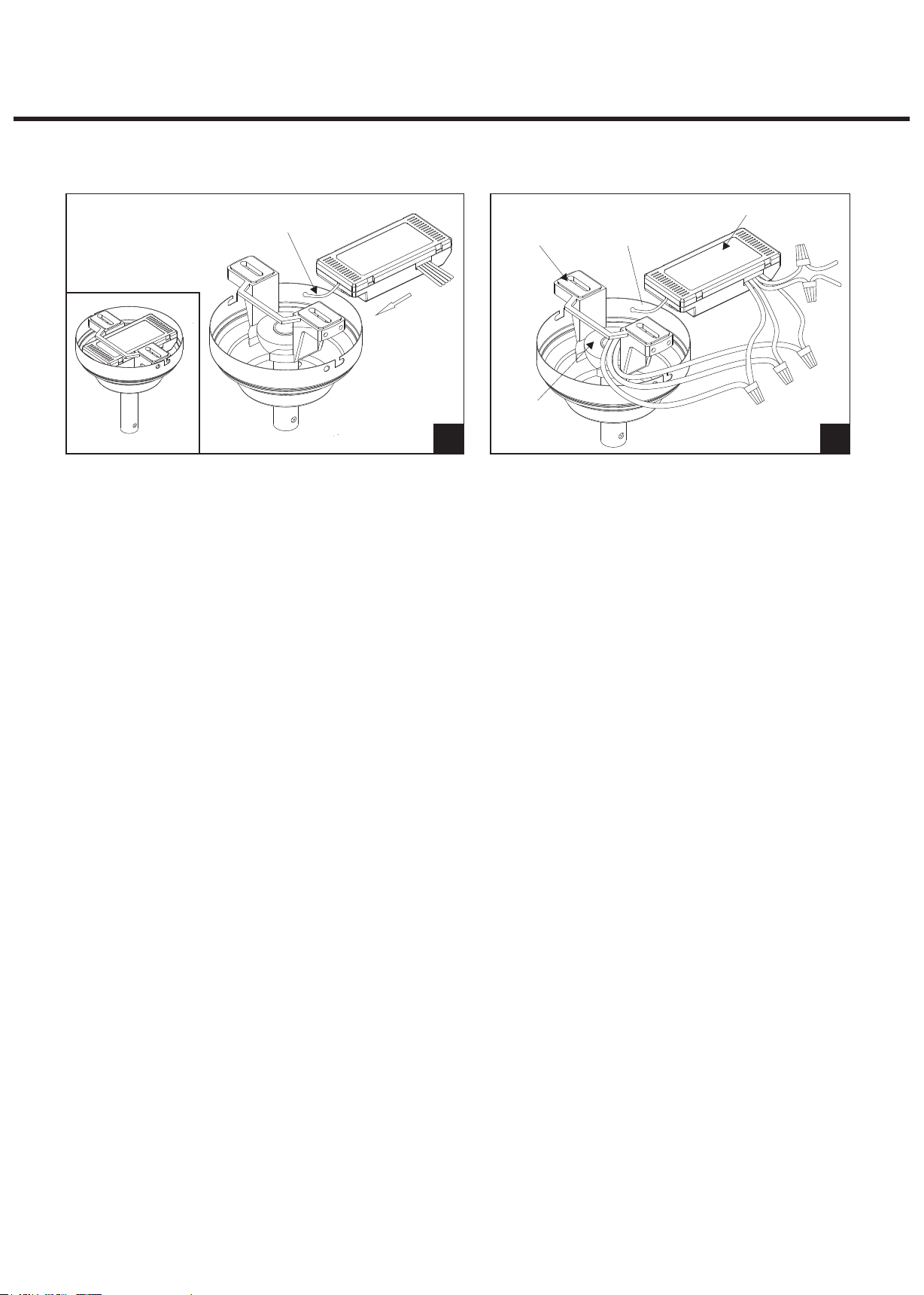
VIEW AFTE R INSTALLA TION
ANTENNA
(LEAVE U NCONN EC TED AND
DO NOT CU T)
HANGER
BRACKET
HANGER
BALL
ANTEN NA:
DO NOT CUT
OR SPLI CE
1 2
RECEIVE R
d
e
a
b
c
1.) Make sure the electric power was turned off and then install the system.
2.) Ceiling fan must be set at HIGH speed and light kit (if any) at ON position by
pulling the“Pull Switch”after installation. Once the connection has been
made, the receiver inserts into the drop rod hanging bracket. The canopy
comes up to cover the receiver and bracket.(See Fig.1)
3.) Make Wi re Connection.(See Fig.2)
a.The Motor white wire to the white “TO CO M”wire from Receiver with a wire nut.
b.The Motor black wire to the black “TO MO TO R L”wire from Receiver with a wire nut.
c.The Motor blue wire to the blue “TO L IGH T” wire from Receiver with a wire nut.
d.The white wire from Outlet Box to the white “AC IN N”wire from Receiver with a wire nut.
e.The black wire from Outlet Box to the red “AC IN L” wire from Receiver with a wire nut.
●The ground wire from Outlet Box to the green ground wire from the Hanger Ball and the
green ground wire from the Hanger Bracket with a wire nut.
Make sure all of wire nuts are connected firmly. Tuck all wire nuts and wires carefully up
into the Outlet Box, EXCEPT antenna ,which should remain outside Outlet Box.
 Loading...