

Page 1
SERVICE MANUAL
MODEL: 21TS1020
CHASSIS: 3P66SN
Page 2
EN 1
1.
3P66
Technical Specifications, Connections, and Chassis Overview
1. Technical Specifications, Connections,and Chassis Overview
Index of this chapter
Technical Specifications
Connection Overview
Chassis Overview
Note:
Data below can deviate slightly from the actual situation, due to the different set executions.
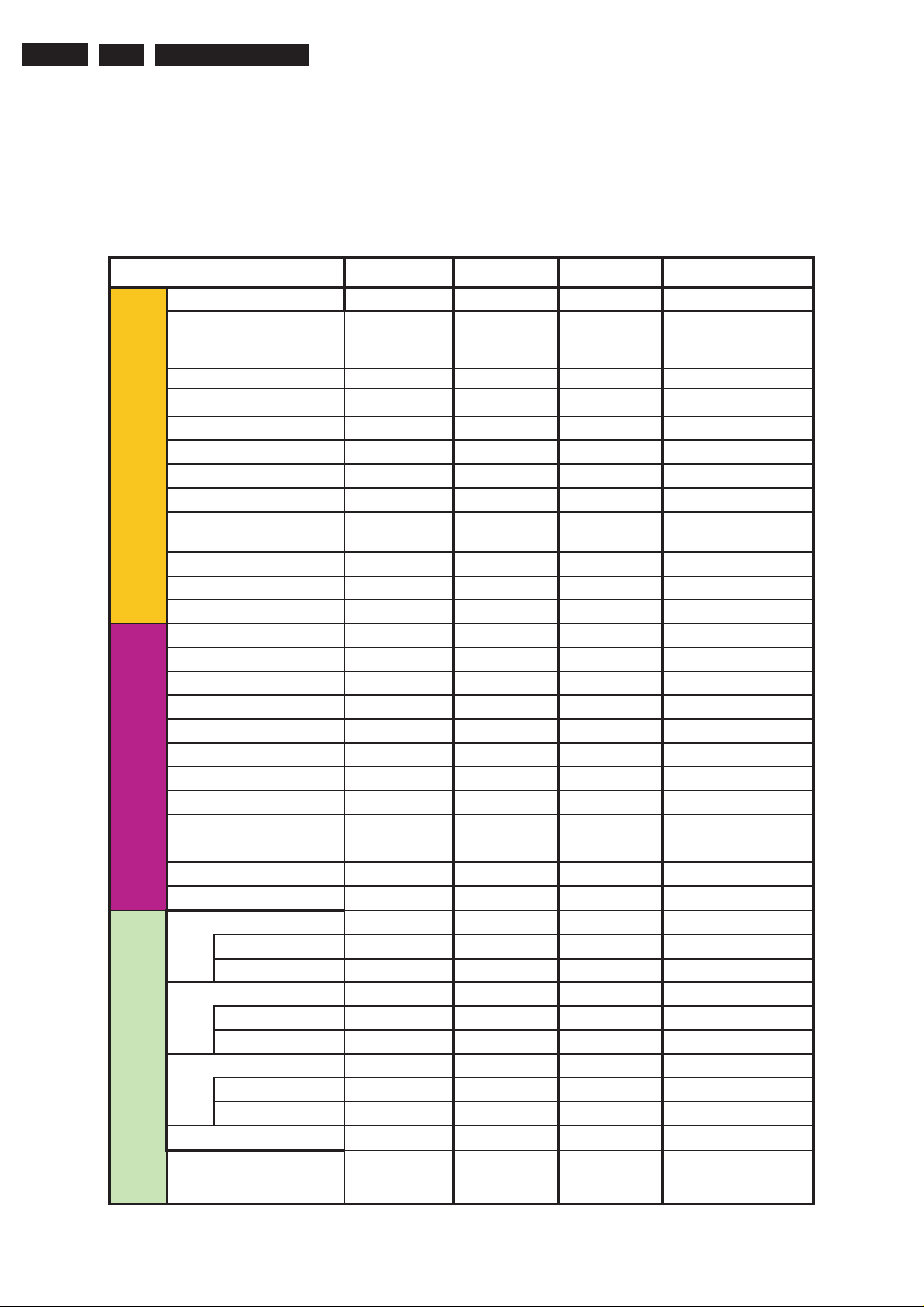
1.1.Technical Specifications
Chassis
CRT Size
Main IC.
Main PCB Size
Color Standard
Sound Receiver
System
Picture
Nicam/A2 (with AV
MTS ( with AV
AV STEREO
SOUND
MONO
System (AV)
Power Source
Power Standby
Maximum Power
PRESET CHANNEL
TUNER TYPE
Antenna InpuT
COM.FILTER
Double Window
Progressive Scan
Freeze
zoom
SVM
Screen saver
Blue Back
Noise Reduction
Pictures effect:
Color Temperature
Black Extend
Tone Control
surround
Tone Control
surround
Tone Control
surround
(mm)
STEREO)
STEREO )
3P66A
14"~21" 14"~21" 14"~21"
14/21RF:TDA11105
21Slim:TDA11135
304X246 304X246 304X246 304X246
PAL PAL/SECAM PAL/SECAM NTSC-M/PAL-M/N
BG/DK/I BG/DK/I BG/DK/I M,N
PAL/NTSC PAL/SECAM/NTSC PAL/SECAM/NTSC PAL/NTSC
AC100-240V 50/60Hz AC100-240V 50/60Hz AC100-240V 50/60Hz AC100-240V 50/60Hz
<3W < 3W < 3W <3W
14"60W;21" REAL FLAT
CRT 80W;21"SLIM CRT
100W
200 200 200 181CH
FS FS FS FS
75 Ohm(Unbalance) 75 Ohm(Unbalance) 75 Ohm(Unbalance)
NO NO NO NO
NO NO NO NO
NO NO NO NO
NO NO NO NO
NO NO NO NO
NO NO NO NO
NO NO NO NO
YES YES YES YES
NO NO NO No
Standard,soft,rich,user Standard,soft,rich,user Standard,soft,rich,user
NO NO NO NO
YES YES YES YES
NO NO NO NO
NO NO NO NO
NO NO NO NO
NO NO NO OPTION
NO NO NO NO
NO NO NO NO
YES YES YES YES
NO NO NO NO
NO NO NO NO
NO NO NO NO
3P66E(RCAMODE)
14/21RF:TDA11106
21Slim:TDA11136
FLAT CRT
80W;21"SLIM CRT
100W
3P66E(SCART MODE)
14/21RF:TDA11106
21Slim:TDA11136
FLAT CRT
80W;21"SLIM CRT
100W
3P66S
14''-21''
TDA11145
14"70W;21" REAL FLAT CRT
90W;21"SLIM CRT 115W
75 Ohm(Unbalance)
Standard,Soft,Rich, User
Audio Output Power ()MAX()
2W+2W 2W+2W 2W+2W 5W+5W
Page 3
Technical Specifications, Connections, and Chassis Overview
3P66 1.
EN 2
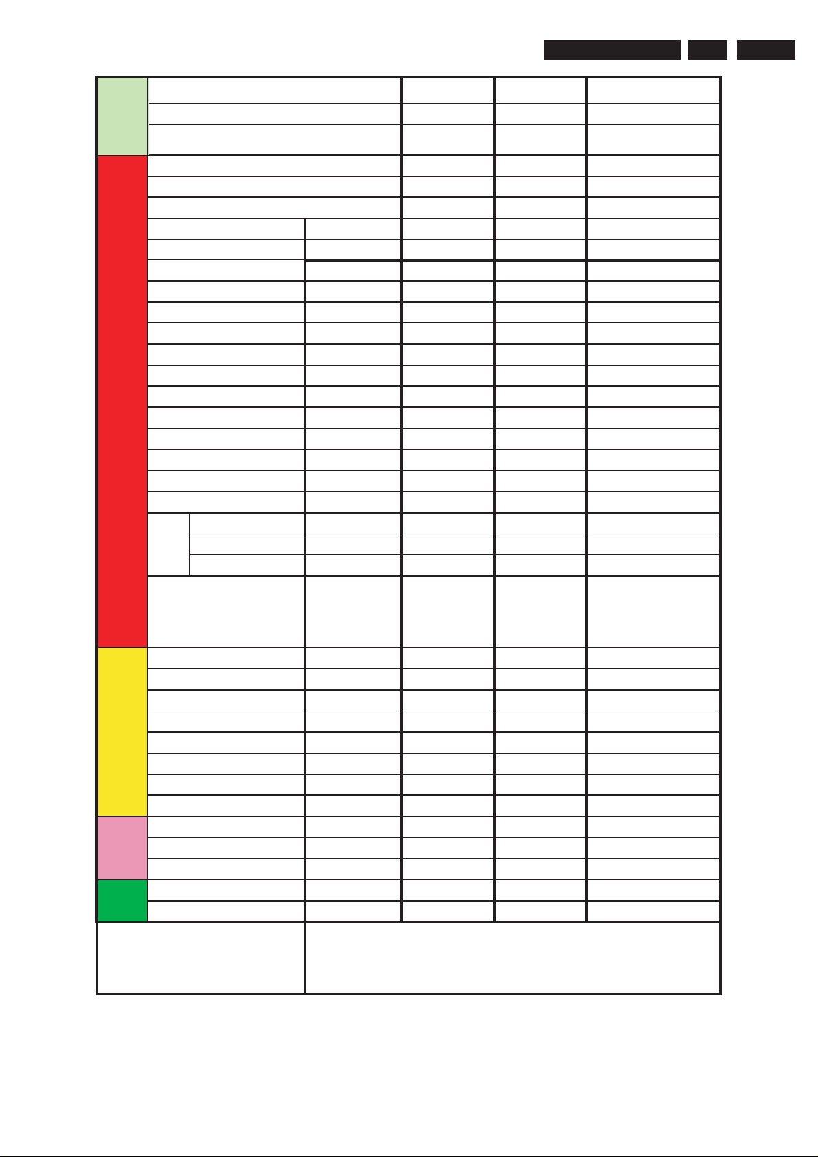
Features
Subwoofer Out
Mute
sounds effect
No signal auto standby
Timer Off/On
Sleep Timer
Rename channel
Favorite channel
Biological Clock
Calendar
Program prearrange
Child Lock
Quick view
Hotel mode
Clock
Game
CCD
V-Chip
High gain tuner
Customer Band Name (OSD)
Mode
Teletext
Pages
X26 Packet
OSD Language
NO NO NO NO
YES YES YES YES
No NO NO NO
15 MIN 15 MIN 15 MIN 15Min
YES YES YES YES
YES YES YES YES
NO NO NO NO
NO NO NO NO
NO NO NO NO
NO NO NO NO
NO NO NO NO
YES YES YES YES
YES YES YES YES
NO NO NO NO
YES YES YES YES
NO NO NO NO
NO NO NO YES
NO NO NO YES
NO NO NO NO
NO NO NO NO
NO NO NO NO
NO NO NO NO
NO NO NO NO
ENGLISH ,
RANCAIS,Portuguese,T
URKEY,ARABIC,FARSI,
RUSSIA,SPAIN,THAI,VI
ETNAM
ENGLISH,
FRANCAIS,Portuguese,
TURKEY,ARABIC,FAR
SI,RUSSIA,SPAIN,THAI
,VIETNAM
ENGLISH,
FRANCAIS,Portuguese,
TURKEY,ARABIC,FAR
SI,RUSSIA,SPAIN,THAI
,VIETNAM
English,French,Portuguese,Spanis
h
Terminal
s
Certification
Other
RCA Jack
SCART
AV In-Front
AV Input-Rear
AV Output
earPhone
YUV
S-Video In
UL
CB
CE/EMC
Handset
Option feature cost
Applicable Cabinet
YES YES NO YES
NO NO YES NO
111
YES YES YES
NO NO NO NO
YES YES NO YES
NO NO NO NO
NO NO NO NO
YES YES YES YES
YES(OPTION) YES(OPTION) YES(OPTION) NO
RC13 RC13 RC13 RC13
YES
14NK,14NX,14NZ,14NI,14NS,14N03,14N01,14N02,14N07,21NX,21NZ,21T05,21N0
5,21NK,21NI,21TN,21TI,21T15,21N15,21NS,21N03,21T03,21N01,21T01,21N02,21
N07,21T07,21N0C,21TOC,21T91,21N91,21N10,21T10,21D93,21T11,21U10,21D11,
21D88,21U11,21U16,21N12,21T12,21U12
1
Page 4
EN 3
1.
3P66
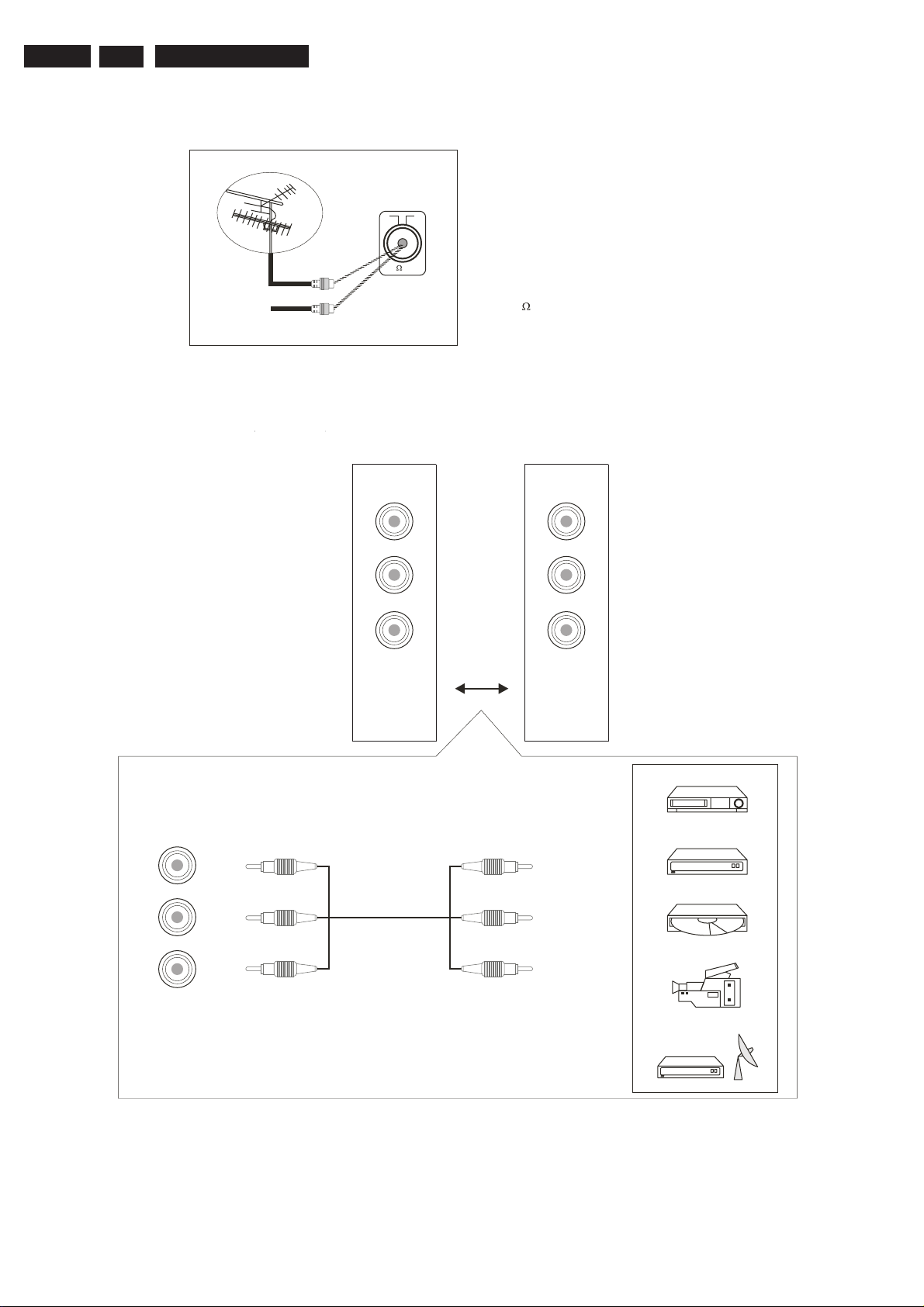
1.2. Connections
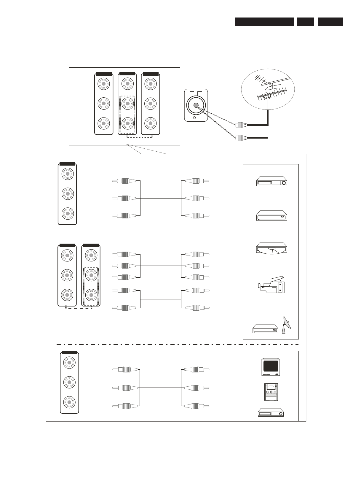
Connecting the Aerial(or Cable Television
Cable
Television
Network
Front(or side)Audio/Video Input(option)
SOCKETS
Technical Specifications, Connections, and Chassis Overview
Network)
To view television channels correctly ,a signal
must be received by the set from one of the
following sources:
*An outdoor aerial
*A cable television network
75 ANT
Plug the aerial or cable network input cable to
the 75 coaxial socket on the rear of the
television.
VIDEO
LEFT
RIGHT
VIDEO
LEFT
RIGHT
RIGHT
LEFT
VIDEO
or
AV2 IN
V
L
R
V
L
R
AV2 IN
VCR
Decoder/
video game device
Video disc player
Camcorder
Satellite receiver
Page 5
Technical Specifications, Connections, and Chassis Overview
3P66
1.
EN 4
STEREO A
V&YUV
AV1 IN
VIDEO
LEFT
AV OUT
VIDEO
LEFT
RIGHT
AV1 IN
VIDEO
LEFT
RIGHT
V
L
R
YCbCr IN
Y
Cb
Cr
75 ANT
V
L
R
Cable
Television
Network
VCR
Decoder/
video game device
RIGHT
YCbCr IN
Y
Cb
Cr
AV OUT
VIDEO
LEFT
RIGHT
AV1 IN
VIDEO
LEFT
RIGHT
Y
Cb
Cr
Video disc player
Y
Cb
Cr
L
R
V
L
R
L
R
V
L
R
Camcorder
Satellite receiver
TV
Amplifier
VCR
Page 6

EN 5
1.
3P66
Technical Specifications, Connections, and Chassis Overview
PERIPHERAL EQUIPMENT CONNECTIONS
There is a wide range of audio and video equipment that can be connected to your TV.
Connection diagrams at the end of this section show
Aerial socket
1. Connect the RF out socket of the VCR to the aerial socket on the back of the set.
2. Connect the aerial cable to the RF aerial in socket of the VCR.
3. Select the program number where the VCR channel is stored.
4. Press the PLAY button on the VCR.
Audio/ Video in
1. Connect the audio/video out sockets of the VCR to audio/video in sockets of the set.
2. Press the AV/TV button to select AV.
3. Press the PLAY button on the VCR.
The VCR playback picture appears on the screen.
Precautions when connecting to other equipments
When using external equipment with this TV, please read the
Switch off all power supplies to the equipment and TV before connection.
Always ensure that the input
sockets
and output terminals are correctly connected..
.
you where the different equipment
instruction manual of
the
should be connected at the backside of the TV.
external equipment.
Page 7
Technical Specifications, Connections, and Chassis Overview
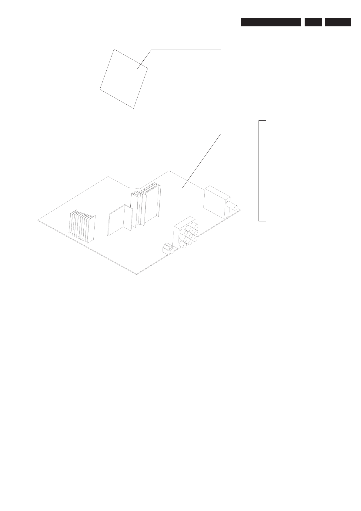
1.3. ChassisOverview
CRT PANEL
3P66
1.
EN 6
MAIN
CHASSIS
PANEL
POWER SUPPLY
LINE DEFLECTION
FRAME DEFLECTION
TUNER IF
AV I/O
AUDIO / VIDEO
VIDEO IF SOUND IF
CPU CONTROL
AUDIO AMPLIFIER
Page 8

EN 7
2.
3P66
Safety Instructions
2.Safety Instructions
2.
1. Power-supply cords should be routed so that they are not likely to be walked on or nagged by items placed
upon or against them. Pay particular attention to cords at doors, plugs, receptacles, and the point where they exit
from the product. When the power cord or plug is damaged or frayed, unplug the TV from the wall outlet and refer
servicing to your authorized dealer.
2. Do not overload wall outlets, extension cords, or convenience receptacles on other equipment as this can result
2.
in a risk of fire or electric shock.
3. Unplug the TV product from the wall outlet before cleaning. Do not use liquid cleaners or aerosol cleaners. Use a
2.
damp cloth for cleaning.
4. If the TV should be dropped and/ or broken, it could result in an injury, and continued use could result in fire or
2.
electrical shock. Immediately turn off the power switch, disconnect the power plug from the power outlet and contact
your authorized dealer.
5. Do not insert liquids or foreign object. Penetration of liquids or foreign objects could result in fire or electrical
2.
shock.
6. Do not attempt to service the TV yourself. Opening or removing covers can expose you to high voltage and other
2.
dangerous conditions. Refer all servicing to your authorized dealer.
7. Do not place the TV on an unstable shelf, slant or vibrant surface. The TV may fall, causing serious injury to
2.
human and serious damage to the appliance.
8. Avoid dusty places, since accumulated dust inside the chassis may cause failure of the TV when in high humidity
2.
environment.
9. Do not place the TV near water. For example, a bathroom, a beach, etc.
2.
10. Do not obstruct the ventilation openings of the equipment with items such as newspapers, tablecloth, etc.
2.
11. Do not place the TV on a carpet, sofa or bedding.
2.
12. Keep the TV away from heat sources such as radiators, heaters, stoves and other heat generating products.
2.
13. Do not place the TV in a "built-in" enclosure, unless proper ventilation is provided.
2.
14. Do not place flower vases, pots, cups, cosmetics, liquids such as water, etc on or around the TV.
2.
15. Choose a place where light (artificial or sunlight) does not shine directly on the screen.
2.
16. If the TV does not work properly and you are unable to restore normal operation by following the "troubleshooting"
2.
section in your instruction manual, do not attempt any further adjustment. Unplug the TV and consult your authorized
dealer.
17. Do not touch the controls other than those described in the operating instructions as improper adjustment of
2.
other controls may result in damaging. Please ask your service authorized dealer to restore the TV to normal operation.
18. For added protection for this TV during a lightning storm, unplug it from the wall outlet and disconnect the
2.
antenna or cable system.
19. If a strange sound or smell gives off from the TV, please turn off and unplug it from the wall outlet, then refer to
2.
authorized dealer.
20. To prevent fire, never place any type of candle or naked flames on the top or near the TV.
2.
21. Avoid any kind of impact to the TV. Be special careful not to damage the screen face.
2.
22. If the TV is to remain unused for a period of time. Turn off and unplug it from the wall outlet.
2.
Page 9
MechanicalInstructions
3P66
3.
EN 8
Page 10

EN 9
4.
3P66
Service Modes
4. 3P66SN Service Modes
4.1. Enter and exit service mode4.1. Enter and exit service mode
a. Enter "factory service mode" Press "MENU","Q.VIEW" and "PP" in turn.:
b. Enter "design service mode" : After entering "factory service mode",select"SC"item,then press "8","9"keys.
(Normally "design service mode"is not needed for production line.)
c. Exit service mode: Press"DISPLAY"key to exit service mode.
Adjustment:
In service mode,pressing digital keys directly can enter the corresponding page,pressing "MENU"key can enter
the next page,pressing "SCAN"key can enter prevenient page.
Pressing "UP"and"DOWN"keys can select the items to adjust, pressing"LEFT" and
values.
4.2. BUS OPEN mode4.2. BUS OPEN mode
In service mode, pressing"MUTE"key can enter "BUS OPEN"mode, which is useful for white balance adjustment
using AUTO WHITE BALANCE EQUIPMENT or mass data written into EEPROM. IC. Pressing"MUTE"key again
can exit "BUS OPEN" mode.
4.3. VG2 adjust mode4.3. VG2 adjust mode
Two methods to adjust VG2 voltage:
(1) OSD mode:
This mode is for sets with AKB function(page10 "VG2-MODE"is set to 1 and hardwire is with CCC loop ), adjust
the VG2 potmeter on the FBT till "OK" is displayed.
(2) Horizontal line mode:
This mode is for sets without AKB function(page 10"VG2-MODE" is set to 0 and hardwire is without CCC loop),
adjust the VG2 potmeter on the FBT untill the faint horizontal line appears in dark room(usually only one colour:
Red ,green or blue.
*Note:VG2 voltage is also controled by"VG2-BRI"on page (5).
*Note:
"RIGHT"keys can adjust the
4.4. FACTORY mode4.4. FACTORY mode
In service mode, pressing"PP"key can erter "FACTORY MODE", which is useful for aging in production lines.
Pressing "PP"key again can exit "FACTORY MODE".
4.5. RF AGC adjustment4.5. RF AGC adjustment
a. Receive 571.25MHz , 60dB color bar signal.
b. Enter factory mode and press digital key "03".
c. Measure tuner AGC point voltage, and adjust AGC item till the voltage is (or till picture noise just2.7V 0.1V
disappears) Usually the AGC value is fixed to 20.。
4.6. FOCUS adjudtment4.6. FOCUS adjudtment
a. Receive cross-hatch pattern signal.
b. Set picture to"RICH" mode.
c. Adjust FBT's FOCUS knob till picture is clear.
4.7. SCREEN VOLTAGE adjustment4.7. SCREEN VOLTAGE adjustment
a. The TV set will be set up in the "AV" "STANDARD" mode, no signal input.
b. Enter into adjust factory mode, and press "03" keys to choose "Vg2" item, it will be permitted to enter light
Line mode.
c. In light-Line mode, Rotating screens potential for grid-line level so you can adjust. Press "CH+."or "CH-." Key ,
the by-line can be returned to the state in full screen mode, and then exit it.
4.8. Aging of machine mode4.8. Aging of machine mode
a. When enter into factory mode state, pressing P.P. key will be permitted to enter Aging of machine mode.
b.Press "8"key and "9"key one by one button exit aging mode .
4.9. BTSC alignment method(3P66SN)4.9. BTSC alignment method(3P66SN)
a. FLUKE 54200 trasmitting colour bar Signal frequency at 61.25MHZ Signal strength at 80dB Test 3 under,,,
BTSC settings sound frequency at 300HZ Input signal to 3P66SN Latam RF, turn on TV.()。
Page 11
Service Modes
b. After TV operate normally, use 3P66SN Latam RC to perform Auto-search or select CH03.
c. Enter factory mode (exact details refer to 3P66SN alignement instruction), use Multimeter
measure at J852 to achieve a reading of 0.25 0 .02 Vrms.
d. Enter factory mode page 7 in the selection of BTSC-L1, use multimeter FLUKE 87 Ⅲ to measure R860(CHL),
and R862(CHR) ( effective L, R audio output from TDA9580 BTSC demodulation), Adjust BTSC-L1 to achieve
CHR, CHL at 0.5 0.02 Vrms.
e. FLUKE 54200 transmitting colour bar Signal frequency at 61.25MHZ Signal strength at 80dB, Item Test1,,
under BTSC, BTSC-MOD to set Stereo.
f. Use Dual Trace Oscilloscope, CH1 measures R860 (CHL), CH2 measures R862(CHR).Enter Factory mode
page 7, Select Stereo in BTSC-MODE, adjust BTSC-A1 and BTSC-A2, to achieve the clearest, cleanest, least
interdependent waveforms of 300Hz and 3kHz. Also adjust BTSC-TC, to achieve the best waveform of 300Hz
and 3kHz. (Suggest default value of 4)
g. “Reduce the signal strength of FLUKE 54200 to 30dB, transmitting colour bar, Signal frequency at 61.25MHZ,
BTSC-Stereo, SAP-MOD, audio frequency at L=300Hz, R=3kHZ. Adjust values of BTSC-ST and BTSC-SP while
pressing “SAP” key on the RC, until no detection of Stereo and SAP, then Adjust values of BTSC-ST and
BTSC-SP while pressing “SAP” key on the RC, until proper detection of Stereo and SAP. Final confirmation of
values for BTSC-ST and BTSC-SP.”
3P66
4.
FLUKE87Ⅲto
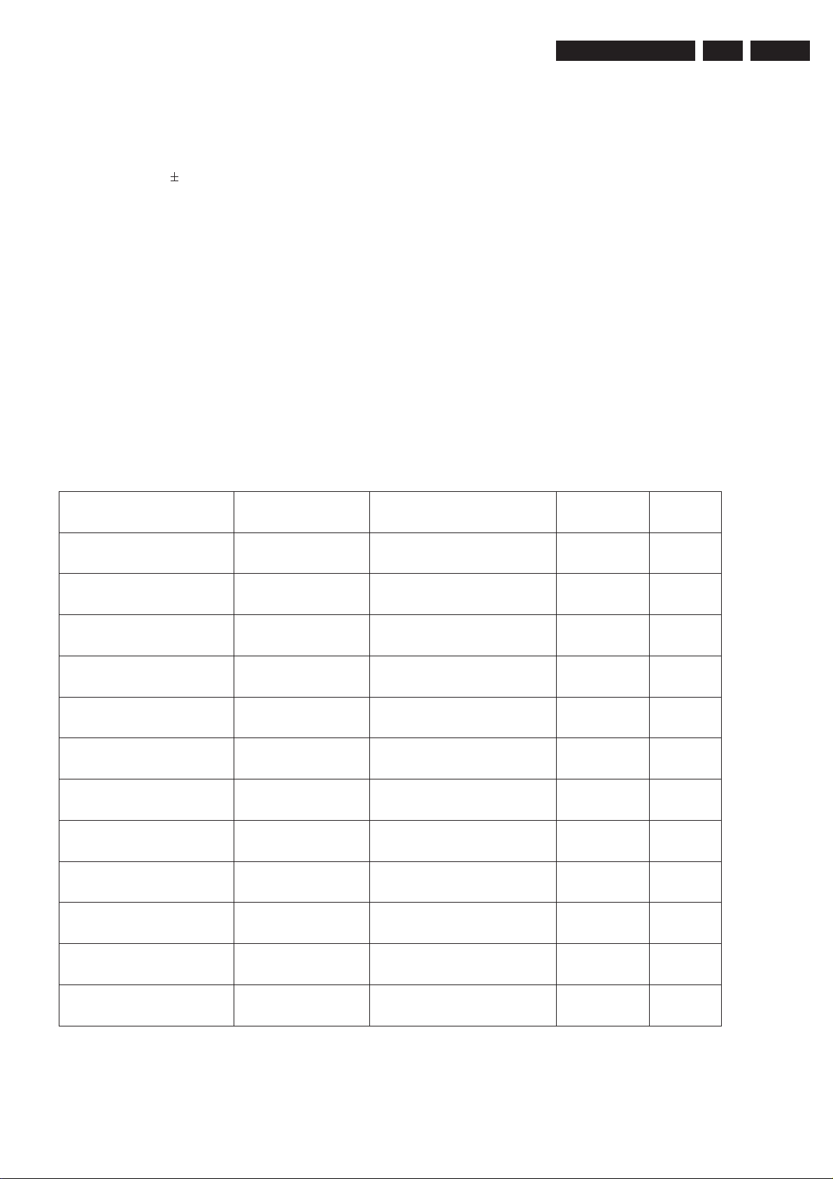
4.10. Factories parameters of the adjustment4.10. Factories parameters of the adjustment
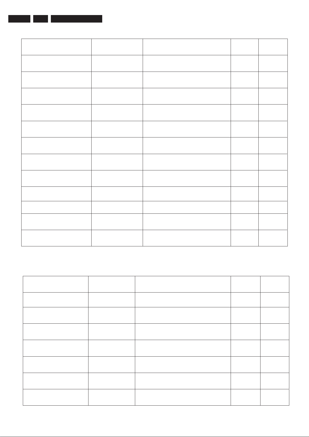
Debugging items and directive from the page " 0" to page" 15" consists of 16 items, and a "predetermined
adjustment page" Belows are testing the items specified,:
EN 10
(0) Page 0
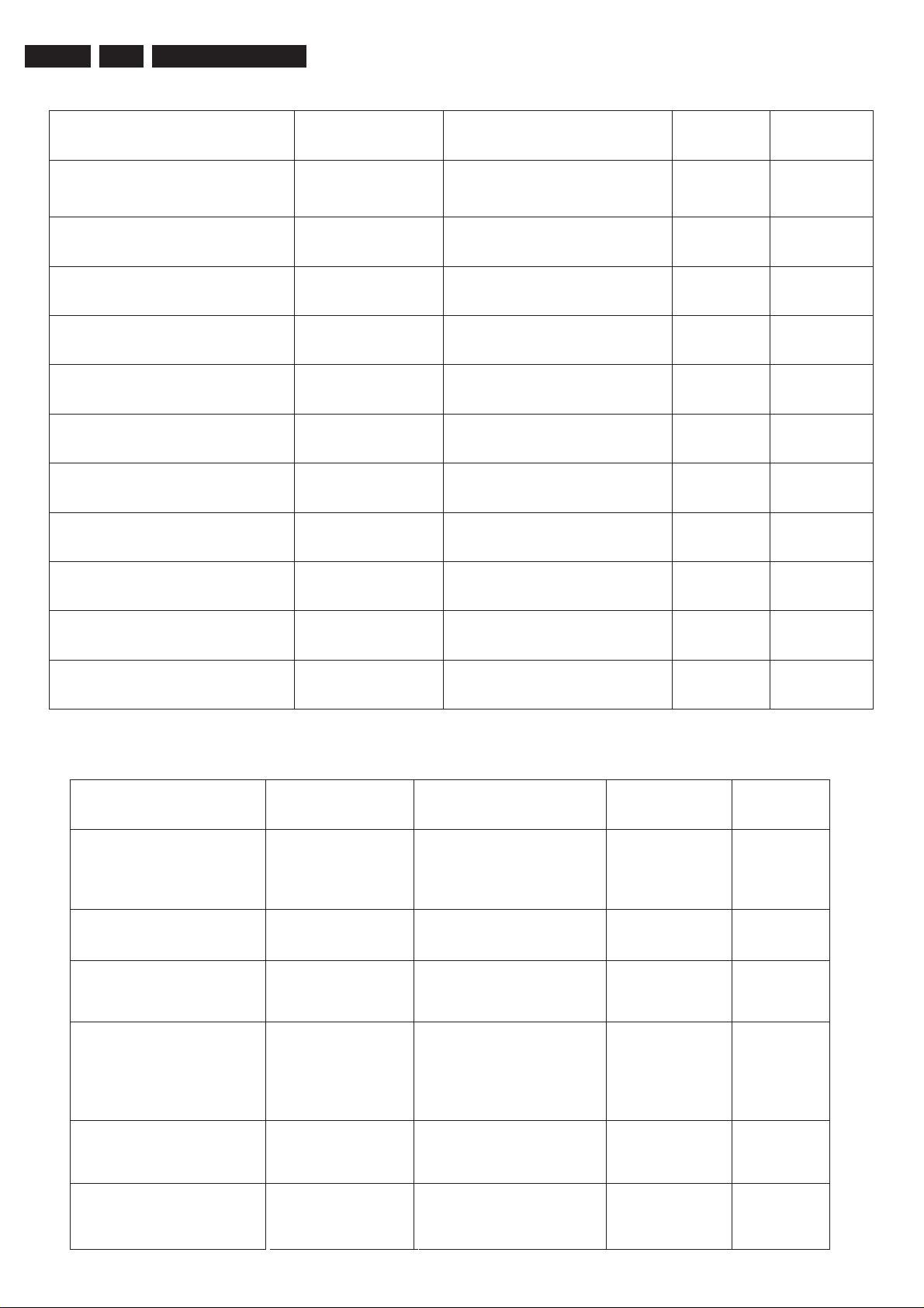
Service setting OSD display Description Value DefaultService setting OSD display Description Value Default
Horizontal shift HSH 50Hz Horizontal center 0…63 35
Horizontal shift HSH-60 60Hz Horizontal center 0…63 30
EW Width EWW 50Hz EW Width 0…63 50
EW Width EWW-60 60Hz EW Width 0…63 50
Vertical Slope VSL 50Hz Vertical Slope 0…63 30
Vertical Slope VSL-60 60Hz Vertical Slope 0…63 30
Vertical Shift VSH 50Hz Vertical Shift 0…63 35
Vertical Shift VSH-60 60Hz Vertical Shift 0…63 35
Vertical Amplitude VAM 50Hz Vertical Amplitude 0…63 25
Vertical Amplitude VAM-60 60Hz Vertical Amplitude 0…63 25
S-correction SC 50Hz S-correction 0…63 20
S-correction SC-60 60Hz S-correction 0…63 20
Page 12
EN 11
4.
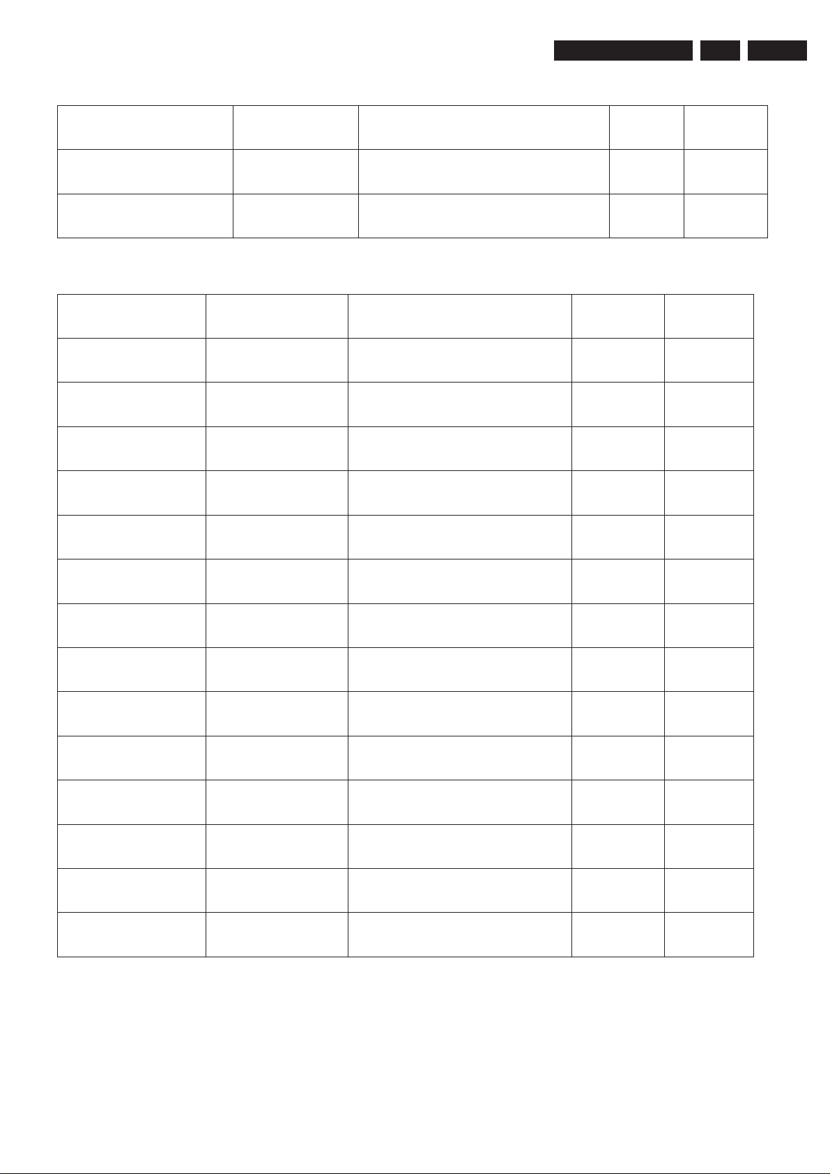
(1) Page 1
3P66
Service Modes
Service setting OSD display Description Value DefaultService setting OSD display Description Value Default
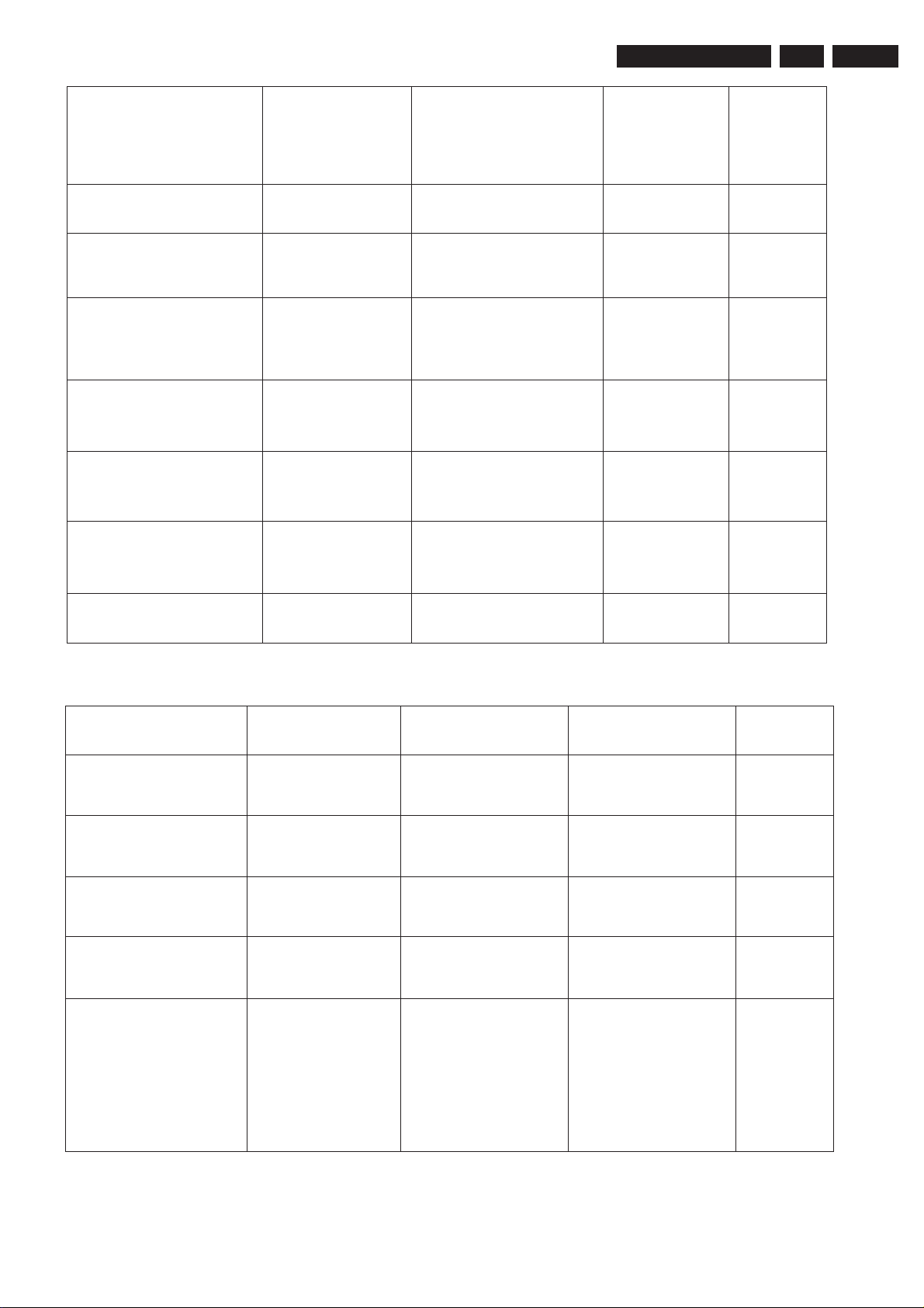
EW parabola/width PW 50Hz EW parabola/width 0…63 40
EW parabola/width PW-60 60Hz EW parabola/width 0…63 40
EW trapezium TC 50Hz EW trapezium 0…63 25
EW trapezium TC-60 60Hz EW trapezium 0…63 25
Upper corner parabola UCP 50Hz Upper corner parabola 0…63 40
Upper corner parabola UCP-60 60Hz Upper corner parabola 0…63 40
Lower corner parabola LCP 50Hz Lower corner parabola 0…63 42
Lower corner parabola LCP-60 60Hz Lower corner parabola 0…63 42
Horizontal
Horizontal
parallelogram
parallelogram
HPAR 50Hz
Horizontal
HPAR-60 60Hz Horizontal
parallelogram
parallelogram
0…63 28
0…63 28
Horizontal bow HBOW 50Hz Horizontal bow 0…63 35
Horizontal bow HBOW-60 60Hz Horizontal bow 0…63 35
(2) Page 2
Service setting OSD display Description Value DefaultService setting OSD display Description Value Default
Black level offset C BLC
Common
course
black
Black level offset R BLR Fine black level offset R 0…63 33
level
offset
0…63 7
Black level offset G BLG Fine black level offset G 0…63 35
Black level offset B BLB Fine black level offset B 0…63 36
White point R WPR White point R 0…63 42
White point G WPG White point G 0…63 31
White point B WPB White point B 0…63 48
Page 13
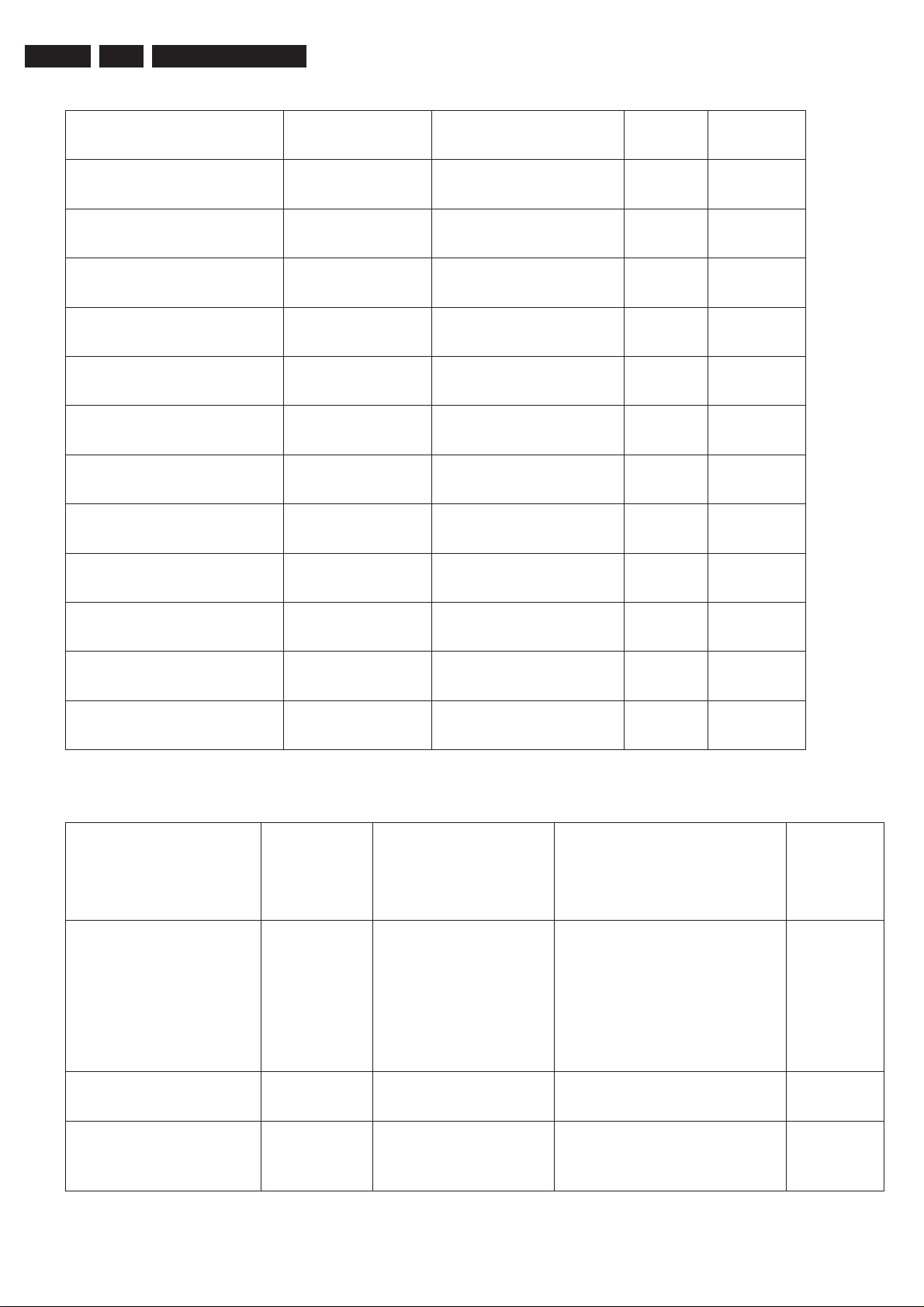
(3) Page 3
Service Modes
3P66
4.
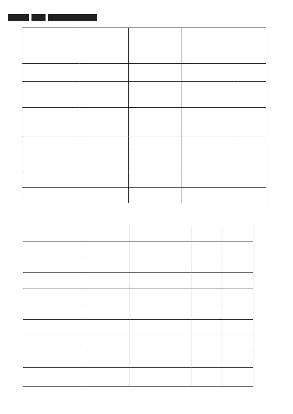
Service setting OSD display Description Value DefaultService setting OSD display Description Value Default
AGC Take over AGC AGC Take-over 0…63 20
VG2 VG2 Adjustment Vg2 voltage 0…63 25
(4) Page 4
Service setting OSD display Description Value DefaultService setting OSD display Description Value Default
Speech treble S-TR Speech treble 0…63 24
Speech bass S-BA Speech bass 0…63 42
Music treble M-TR Music treble 0…63 42
EN 12
Musia bass M-BA Music bass 0…63 48
Theatre treble T-TR Theatre treble 0…63 32
Theatre bass T-BA Theatre bass 0…63 48
AV curve offset AV-OF AV curve offset compare TV -31…+32 -3
Volume curve V-05 0-5 Volume curve 0…81 40
Volume curve V-10 5-10 Volume curve 0…81 55
Volume curve V-20 10-20Volume curve 0…81 63
Volume curve V-30 20-30Volume curve 0…81 67
Volume curve V-40 30-40Volume curve 0…81 69
Volume curve V-50 40-50Volume curve 0…81 70
Volume curve V-63 50-63Volume curve 0…81 80
Page 14
EN 13
4.
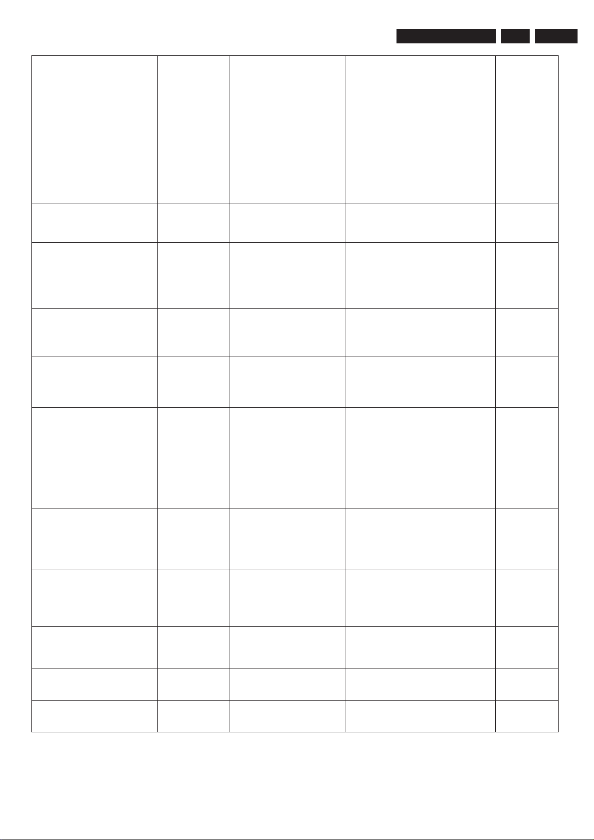
(5) Page 5
3P66
Service Modes
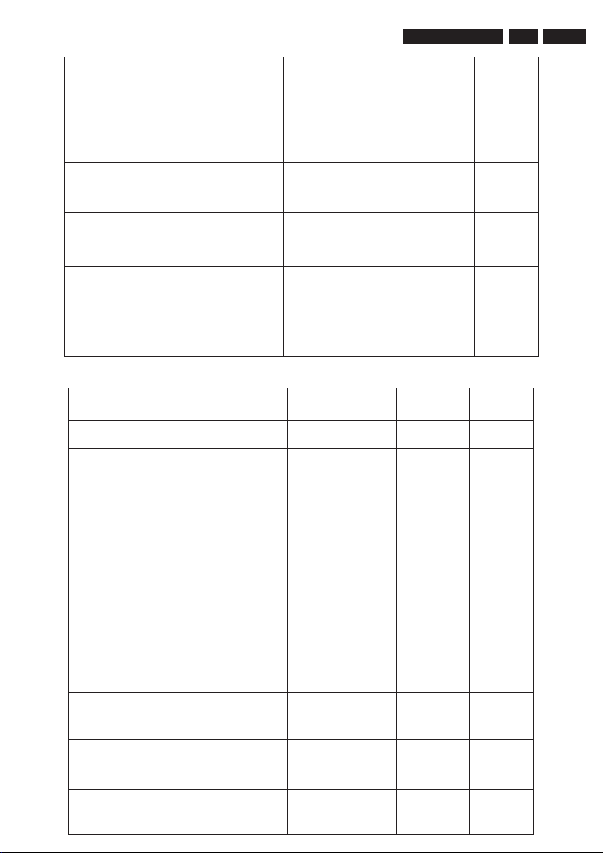
Service setting OSD display Description Value DefaultService setting OSD display Description Value Default
Soft brightness S-BRI Soft brightness 0…63 35
Soft color S-COL Soft color 0…63 25
Soft contrast S-CON Soft contrast 0…63 30
Soft sharpness S-SHA Soft sharpness 0…63 35
Nature brightness N-BRI Nature brightness 0…63 35
Nature color N-COL Nature color 0…63 25
Nature contrast N-CON Nature contrast 0…63 40
Nature sharpness N-SHA Nature sharpness 0…63 60
Rich brightness R-BRI Rich brightness 0…63 40
Rich color R-COL Rich color 0…63 30
Rich contrast R-CON Rich contrast 0…63 60
Rich sharpness R-SHA Rich sharpness 0…63 63
(6) Page 6
Service setting OSDService setting OSD
Description Value Default
display
IFA IFB IFC IF PLL demodulator
frequency setting
0: 58.75MHz
1: 45.75MHz
2: 38.90MHz
3: 38.00MHz
4: 33.40MHz
5: 33.90MHz
1
AGC Speed A SPD AGC Speed 0..3 1
Noise reduce NR Noise reduce(effect
when reopen TV)
0: OFF
1: ON
0
Page 15
Service Modes
3P66
4.
EN 14
BKS&BSD Register BKS BKS&BSD Register
BKS(Black stretch
switch):
setting
0:off 1:on
BSD(Black stretch depth):
0: 15 IRE 1: 30 IRE
BKS=1(default)
0: BSD=0
1: BSD=1
Blue screen B B Blue screen(effect
when reopen TV)
0: No blue screen
1: blue screen
Video mute V-M Video mute 0: No black screen when
switch off
1: black screen when
switch off
3P66
selection
or 5P66
3 or 5 3P66 or 5P66
selection(AV
switch )
0: 3P66
1: 5P66
1
1
0
AV POC Setting A-POC AV POC Setting 0: POC=0
1: POC depend on IFI
TV POC Setting T-POC TV POC Setting 0: POC depend on LOCK
or SL
1: POC depend on LOCK
or IFI
2: POC depend on LOCK
or SL or IFI
Blue screen condition BLUE Blue
condition
screen
0: depend on program
1: AV depend on IFI
TV depend on IFI or SL
Switch off condition OFF Switch off condition 0: depend on program
1: AV depend on IFI
TV depend on IFI and
VG2 MODE VG2-Mode VG2 MODE 0: light –Line mode
1: character mode
1
1
1
0
SL
0
VSD-Bri VSD-Bri 0…63 25
CC Delay DELAY CC Delay 0…127 2
Page 16
EN 15
4.
(7) Page 7
3P66
Service Modes
Service setting OSD display Description Value DefaultService setting OSD display Description Value Default
BTSC-MODE MODE BTSC
mode force
0…2
selection
BTSC-ST ST Stereo noise limit 0…15 5
BTSC-SP SP SAP noise limit 0…15 4
BTSC-LI LI Sound input level 0…15 9
BTSC-A1 A1 Separate 0…31 15
BTSC-A2 A2 Separate 0…31 20
BTSC-TC TC Time constant 0…7 4
BTSC-STS STS Stereo level switch 0/1 0
BTSC-DETECT DETECT BTSC detect time 0…255 50
ST-TIMER ST-TIMER Stereo detect count 0…255 0
MONO-TIMER M-TIMER Mono detect count 0…255 0
(8) Page 8
Service setting OSD display Description Value DefaultService setting OSD display Description Value Default
Bass and Treble BAS-TRE Bass and Treble
display in sound
menu
Balance BLANCE Balance display in
sound menu
Disco Gain DISG Gain
selection
of
DISCO
COFF COF Coring of SVM
specification
0: no display
1: display
0: no display
1: display
normal
0:
gain
1: gain 6dB
:coring
0
according to
specification
1: coring off
0
1
0
0
Cap bank switch for
DCXO
PAL-M Cap bank
switch for DCXO
DCXO NTSC DCXO_CAP
setting
PM-M DCXO PAL-M DCXO_CAP
setting
0…3 2
0…3 2
Page 17
Service Modes
3P66
4.
EN 16
PAL-N Cap bank
switch for DCXO
PAL-N DCXO PAL-N DCXO_CAP
setting
0…3 2
1 of volume VOL1 VOL-1 sound curve 0…63 30
AKB AKB Black
current
stabilize
0: active
1: not active
DSA Register DSA Dynamic skin tone
angle
OSD Position O-V50 50Hz OSD vertical
123
0:
degree
117
1:
0…63 35
1
degree
position
OSD Position O-V60 60Hz OSD vertical
0…63 35
position
OSD Position O-HOR OSD
horizontal
0…63 36
position
1
Init NVM INIT Initialize 0/1 0
(9) Page 9
Service setting OSD display Description Value DefaultService setting OSD display Description Value Default
AV1 AV1 AV1 switch 0: no AV1
1: have AV1
S-VIDEO S-VIDEO S-VIDEO switch 0: no s-video
1: have s-video
YUV YUV YUV switch 0: no YUV
1: have YUV
AV2 AV2 AV2 switch 0: no AV2
1: have AV2
MONO IC MONO TV
MONO
selection
0: stereo
1: mono
2:mono(no MTS)
3:no4052,have
MTS(5P66)
1
0
1
1
0
Page 18
EN 17
4.
3P66
Service Modes
Standly remember R-POWER Power station 0:Direct bootstrap
1: Standby
2: remember Last
state
Logo LOGO Logo switch 0: no LOGO
1: have LOGO
Type of LOGO TYPE Type of LOGO 0:normal LOGO
1:Continental
Electric
8th key of board KEY8 8th key of board
option
0: no 8thmute key
th
1:have 8
mute
key
Vertical linearity 5VLIN 50Hz
Vertical
0…63 32
linearity
Vertical linearity 6VLIN 60Hz
Vertical
0…63 32
linearity
2
0
0
0
VCS 5VSCR 50Hz VSCR 0…63 32
VCS 6VCSR 60Hz VSCR 0…63 32
(10) Page10
Service setting OSD display Description Value DefaultService setting OSD display Description Value Default
Sub-brightness SUB-BRI Sub-brightness 0…63 4
Max-brightness MAX-BRI Max-brightness 0…63 63
Sub-contrast SUB-CON Sub-contrast 0…63 5
Max-contrast MAX-CON Max-contrast 0…63 63
Max-colour MAX-COL Max-colour 0…63 63
No signal EWW N-EWW No signal EWW -31…+32 0
ESPANA option ESP Espanish option 0: no
1: have
FRANCE option FRA
Franch option 0: no
1: have
PORTUGAL option POR Po
rtuguese option 0: no 1
1: have
1
1
Page 19
Service Modes
3P66
4.
EN 18
Brightness of black
balance
BT Brightness of black
balance (TV and
YUV)
Contrastness of black
balance
Brightness of white
balance
Contrastness of white
Balance
CT Contrastness of black
and
balance(TV
YUV)
WBT Brightness of white
balance(TV
and
YUV)
WCT Contrastness of white
balance(TV
and
YUV)
VX VX-VAM VX or VAM active for
VX 16:9 VX
NORMAL and VX
EXPAND
0…63 10
0…63 10
0…63 25
0…63 23
0: VX
0
1: VAM
(11) Page 11
Service setting OSD display Description Value DefaultService setting OSD display Description Value Default
Peak white PWL Peak
white
Cathode HDOL Cathode voltage 0…15 10
Offset
IF
demodulator
OIF Correction for DC
offset
in
Mono active MONO-PIN Mono active 0: L&R
FBC&FBC1 register FBC01 FBC: Fixed beam
current
FBC1:
beam current
during switch
limiting
the
IF-PLL
switch off
Fixed
0…15 15
0…63 32
1: Fix R
0:FBC=0
FBC1=0
1:FBC=1
FBC1=0
2:FBC=0
FBC1=1
3:FBC=1
FBC1=1
0
0
PAL-M OF YD0-YD3
SETTING
NTSC OF YD0-YD3
SETTING
AV OF YD0-YD3
SETTING
P-YD PAL-M OF Y
0…15 9
DELAY
N-YD NTSC OF Y
0…15 8
DELAY
A-YD AV OF Y DELAY 0…15 10
Page 20
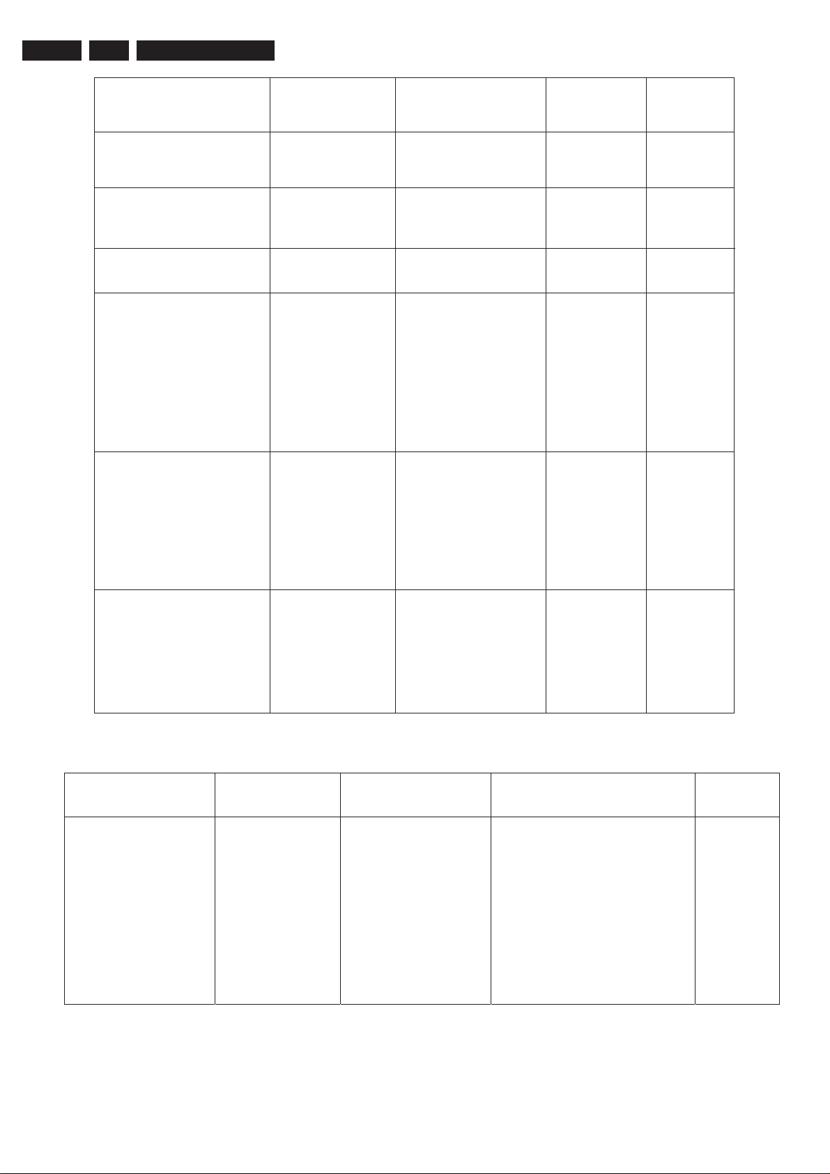
EN 19
4.
3P66
Service Modes
DMPH register DMPH DMPH
not
0:
active
1: active
0(MTS)
1(noMTS)
CBAF0&CBAF1 CBAF0-1 Bass
frequency
selection
CTRF0&CTRF1 CRTF0-1 Treble frequency
selection
CB register CB
Chroma
center
bandpass
frequency
MTXF&MUS&MAT MATRIX 0:NTSC-Japanes
eorPALmatrix
1/3/5/7:
PAL
matrix
4:NTSC-Japanese
matrix
6:NTSC-USA
matrix
FMWB register FMWB 0: FMWB=0
1: FMWB=1
2: continue detect
FML mode
mode
detect
3:
in
a
FML
minute
0..3 0
0..3 0
0: Fsc
1: 1.1 F sc
0…7 4
0…3 0
0
HCO register HCO EHT tracking
0:EHT
tracking
mode
0/1 1
Only
on vertical
1:EHT tracking on
vertical&EW
(12) Page 12
Service setting OSD display Description Value DefaultService setting OSD display Description Value Default
AGN AGN gain
FM
demodulator
0: normal
1: +6dB
0: PAL AGN=0
NTSC AGN=0
1: PAL AGN=0
NTSC AGN=1
2: PAL AGN=1
NTSC AGN=0
3: PAL AGN=1
NTSC AGN=1
0
(
1
(MTS)
NO
MTS
)
Page 21
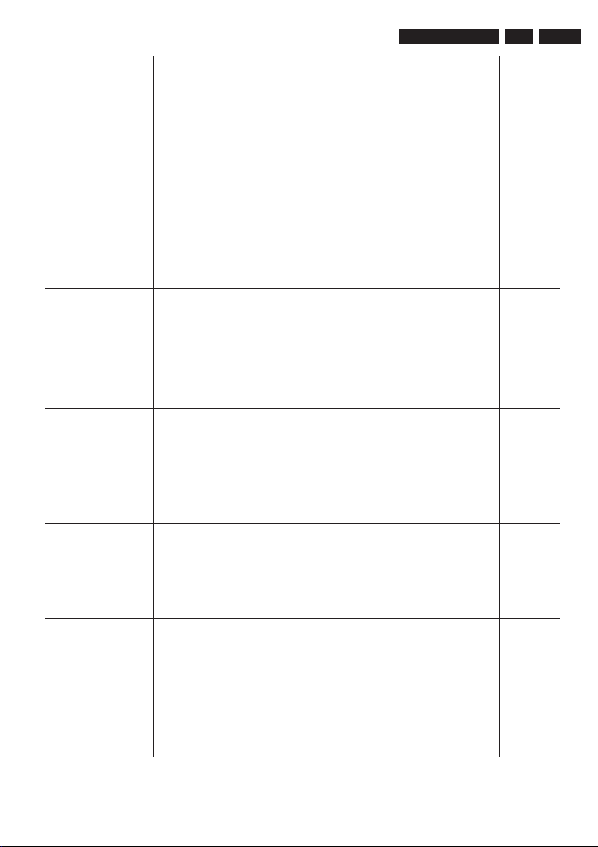
Service Modes
3P66
4.
EN 20
AGNE1&AGNE0 AGNE Extended gain
settings for FM
demodulator
0: normal
1: +3.8dB
2: -6dB
3: -3dB
FMWS1&FMWS2 FMWS Window select for
FM demodulator
0: 100kHz
1: 225kHz
2: 450kHz
3: 900kHz
BPB2 BPB2
Bypass sound
bandpass
filter
section 2
0: active
1: bypass
FFI FF1 Fast filter IF-PLL 0: normal time
1: increased time
COR1&COR2 A-COR Video dependent
coring
For AV
0: off
1: 0 and 20 IRE
2: 0 and 40 IRE
3: 0 and 100 IRE
COR1&COR2 T-COR Video dependent
coring
For TV
0: off
1: 0 and 20 IRE
2: 0 and 40 IRE
3: 0 and 100 IRE
1
1
1
0
2
3
PF0&PF1 PEAK Peaking center 000000b-111111b 56
frequency
and
delay
0: 2.7MHz 190ns
1: 3.1MHz 160ns
bit0,bit1 NTSC PEAK FQ
bit2,bit3 PAL PEAK FQ
bit4,bit5 AV PEAK FQ
2: 3.5MHz 143ns
3: 4.0MHz 125ns
1
FOA&FOB FOA-FOB Phase
constant
00:normal
01:slow
10:OSDmode
time
0:FOA=1 FOB=1 AV
FOA=0 FOB=0 TV
1:FOA=1 FOB=0
2:FOA=0 FOB=1
0
11:fast
DSG of TV TV -DSG Gain from audio
inputs to audio
0: 0dB
1: +6dB
1
outputs(TV)
DSG of AV AV -DSG Gain from audio
inputs to audio
0: 0dB
1: +6dB
1
outputs(AV)
LOGO position LOGO-UD LOGO position 0…63 10
Page 22
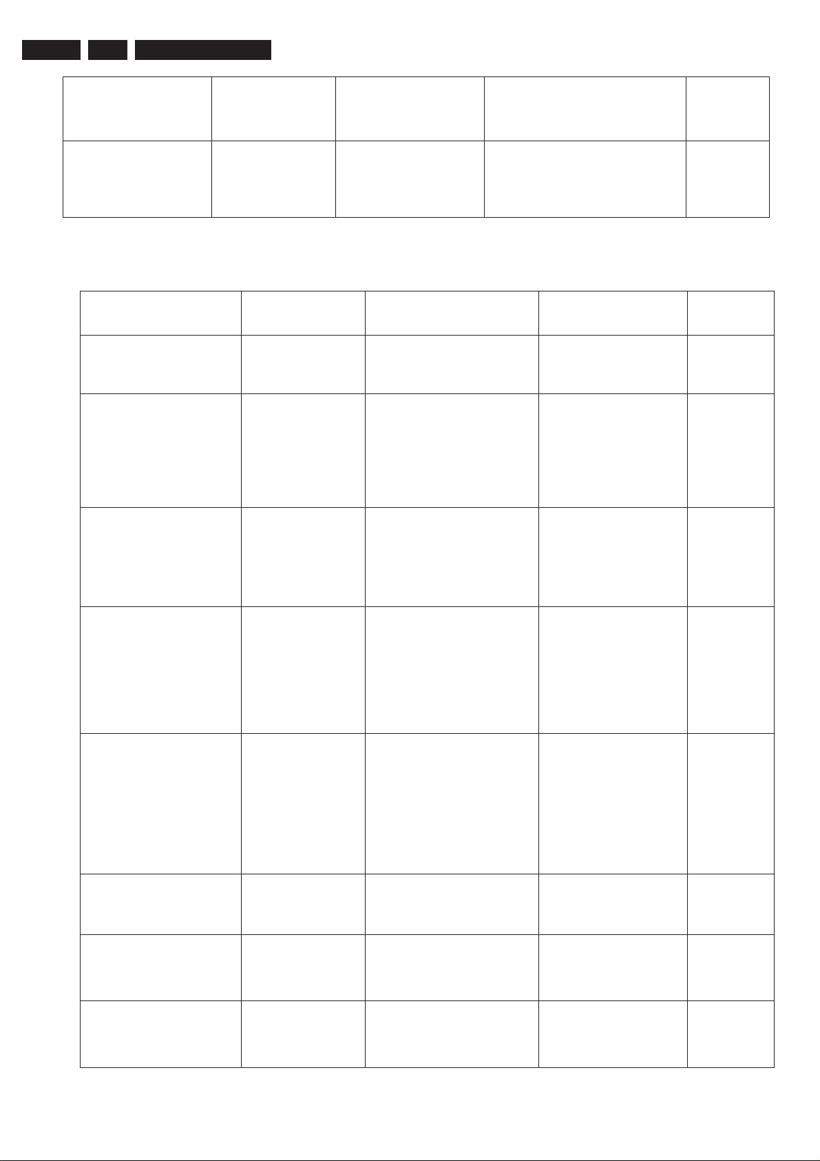
EN 21
4.
3P66
Service Modes
Menu horizontal
position
DSGLS register DSGLS Extra
MENU-H Menu horizontal
position
gain
selection
0…63 35
0: 0dB 1
loudspeaker
outputs
(13) Page 13
1: +6dB
Service setting OSD display Description Value DefaultService setting OSD display Description Value Default
Slicing level SSL
Slicing level FSL Forced slicing level
Slicing level for
horizontal sync separate
for vertical sync
0: 50%
1: 30%
0:slicing
dependent
level
no
noise detector
1:fixed
slicing
level of 60%
0
0
AAS0&AAS1 AAS Black area to switch
off the black strech
0: 12%
1: 20%
2: 6%
3: 8%
SOC0&SOC1 SOC Soft clipping level
0…3 2
00: 0%above PWL
01: 5%above PWL
10: 10%above PWL
11: soft clipping off
MUTE PIN logic M-MUTE MUTE PIN logic 0: for 7266SA
mute L
no mute H
1: for 2052
mute H
no mute L
HBL HBL RGB blanking mode 0:normal blanking
1:wide blanking
2
0
1
WBF WBF Timing of wide blank
(Lift wide blanking)
WBR WBR Timing of wide blank
(Right wide blanking)
0: 3.5us
15: 5.9us
0: 7.8us
15: 10.2us
0
0
Page 23
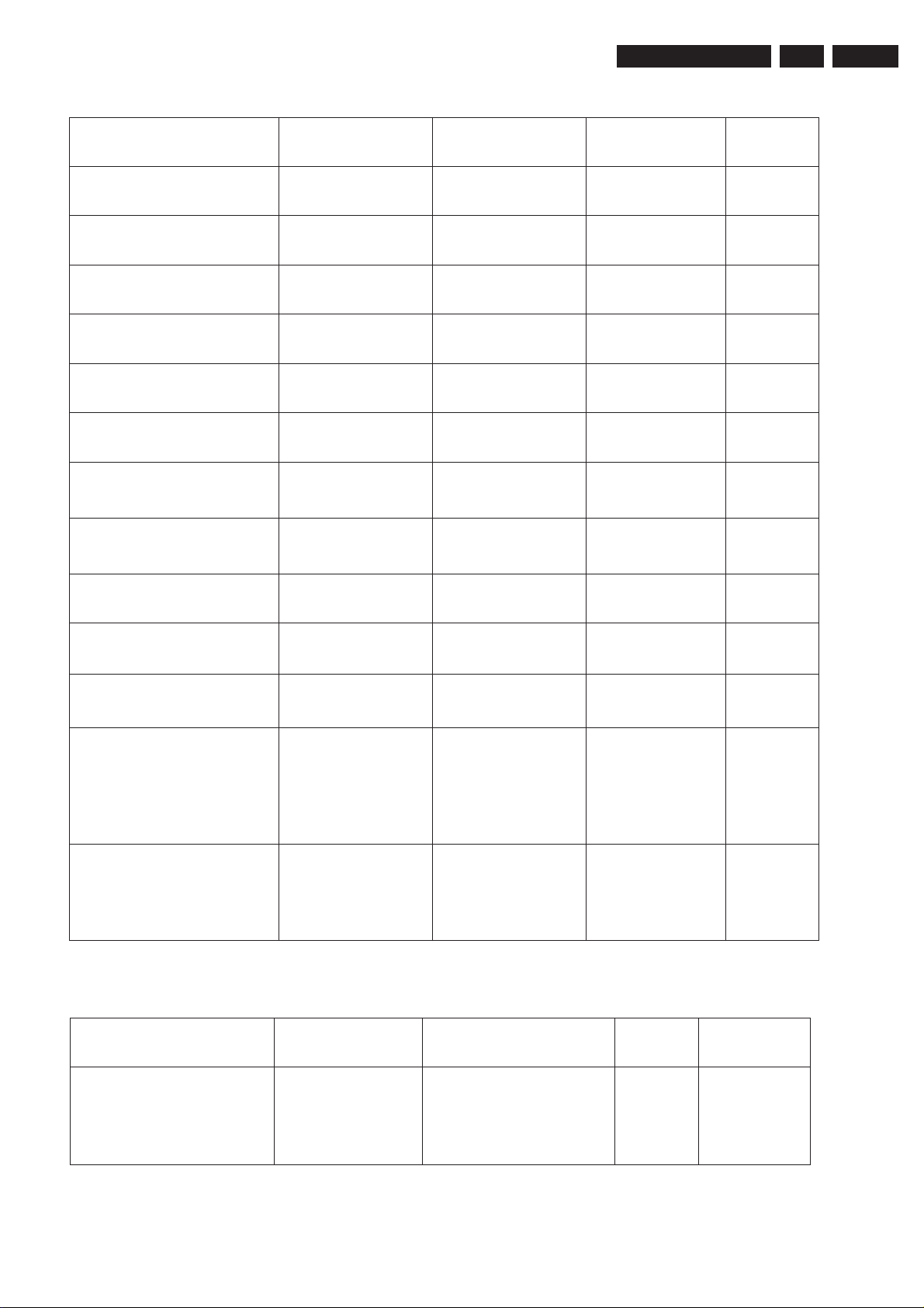
Service Modes
(14) Page 14
3P66
Service setting OSD display Description Value DefaultService setting OSD display Description Value Default
NVM version C0 Char0 48…255
NVM version C1 Char1 48…255
NVM version C2 Char2 48…255
NVM version Y Year 8…10
NVM version M Month 0…12
NVM version D Day 0…31
4.
EN 22
XDT XDT X-ray protection 0: hardware
1: software
XDT SW active XDT-OFFON XDT SW active 0: not active
1: active
SW detect times XDT-TIME SW detect times 0…255 10
STB setting STB Standby 0: standby
1: normal
EVG register EVG Enable vertical
guard
CHSE1&CHSE0
register
CHSE The CHSE
vaule of strong
signal
0: not active
1: active
0: -34dB
1: -37dB
2: -41dB
3: -46dB
Auto low signal identify CHSE ON The switch of
Weak signal
0: turn off
1: turn on
identify
1
1
1
0
0
1
(15) Page 15
Service setting OSD display Description Value DefaultService setting OSD display Description Value Default
Black balance of
YUV
Y-BR Black balance of
YUV (Red)
-32…31 +2
Page 24
EN 23
4.
3P66
Service Modes
Black balance of
Y-BG Black balance of
YUV
Black balance of
Y-BB Black balance of
YUV
White balance of
Y-WR Black balance of
YUV
Black balance of
Y-WG Black balance of
YUV
Black balance of
Y-WB Black balance of
YUV
4.11. White Balance auto-adjustment4.11. White Balance auto-adjustment
White
CPU
CPU Sub address
YUV (Green)
YUV (Blue)
YUV (RED)
YUV (Green)
YUV (Blue)
-32…31 0
-32…31 +3
-32…31 +2
-32…31 0
-32…31 0
NVM
NVM Sub
Balance
Item
Slave
address
(TDA11135,11136,12156,11145,12165
/ TDA11105,TDA11106)
Slave
address
address
BLOR 0x8A 0x17 / 0x09 0xa0 0x003b
BLO G 0x8A 0x1 8 / 0x0 a 0xa0 0x003 c
BLO B
WPR
WPG
WPB
0x8A
0x8A
0x8A
0x8A
0x1 6 / 0x0 b
0x 2 0
0x21/
0x22/
/0x12
0x 1 3
0x 1 4
0xa0
0xa0
0xa0
0xa0
0x003 d
0x003 e
0x003 f
0x004 0
Page 25
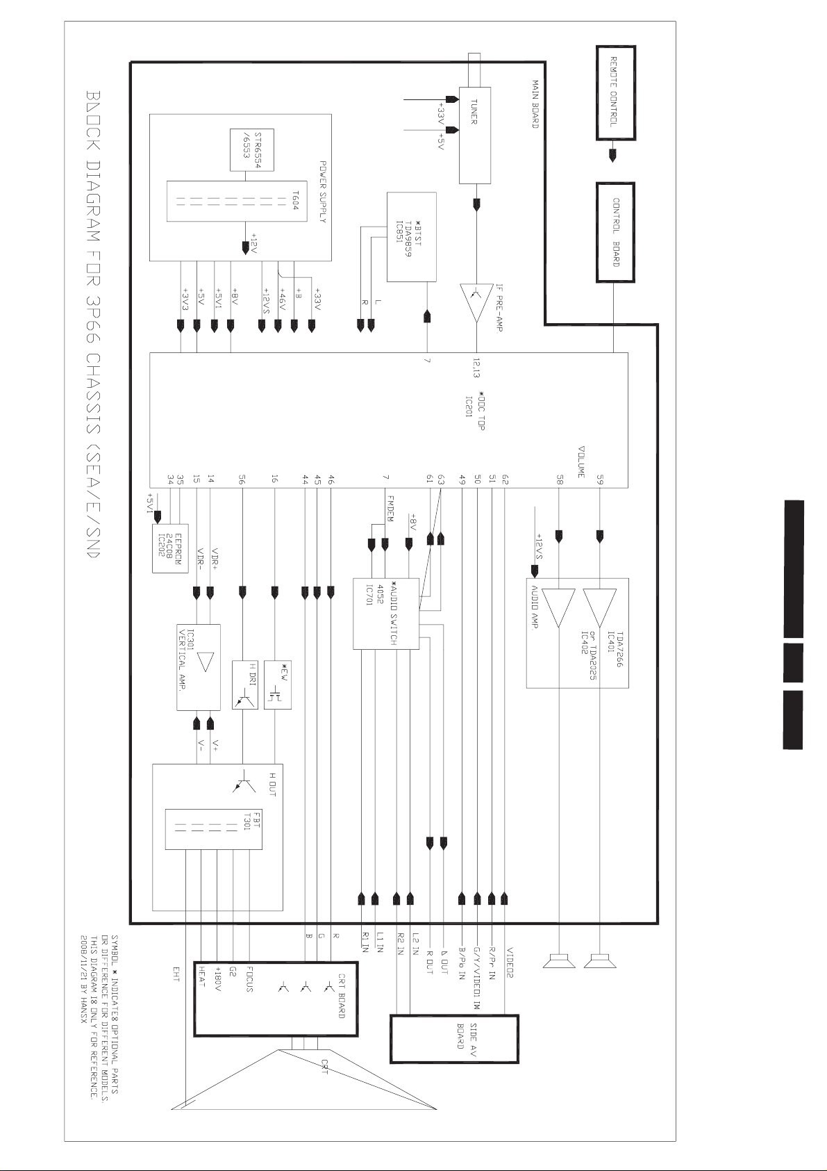
Block Diagram Chassis
3P66
5.
E24
N
Page 26
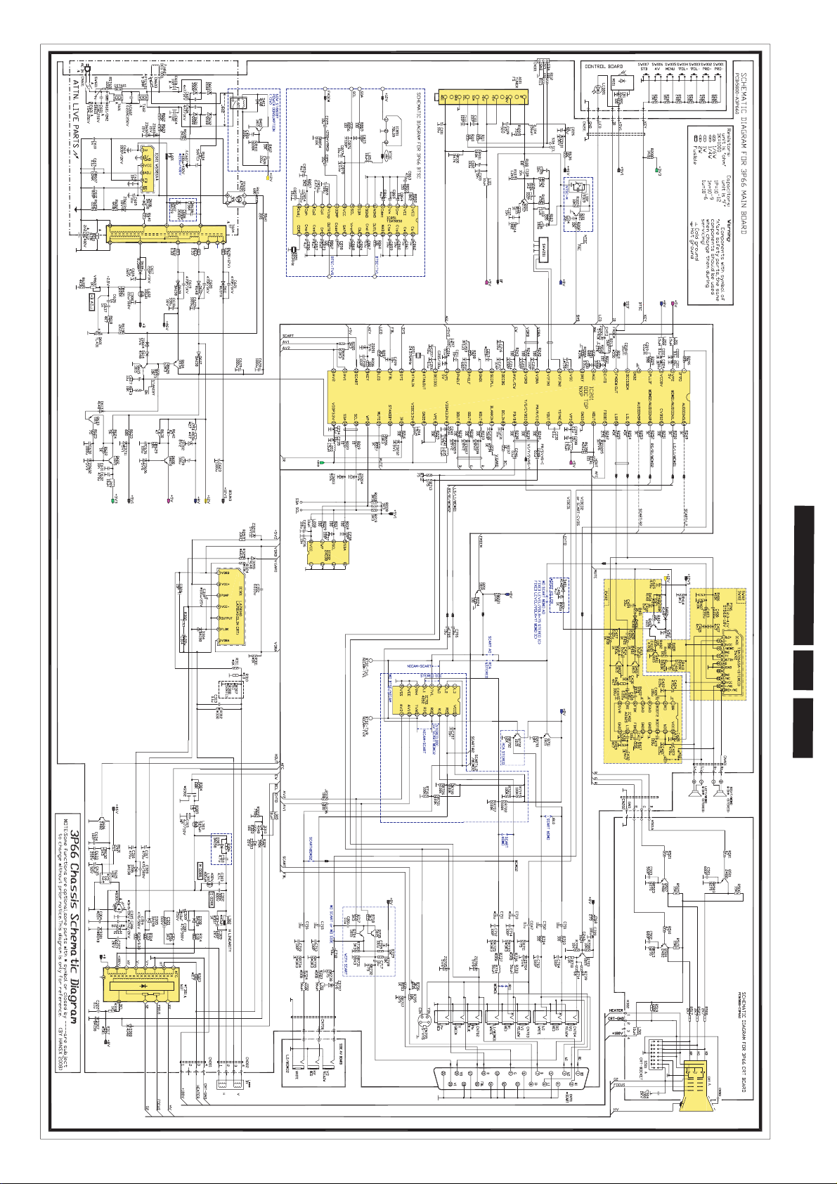
Circuit
Diagrams
Circuit Diagrams and PWB Layouts
3P66
6.
E25
N
Page 27
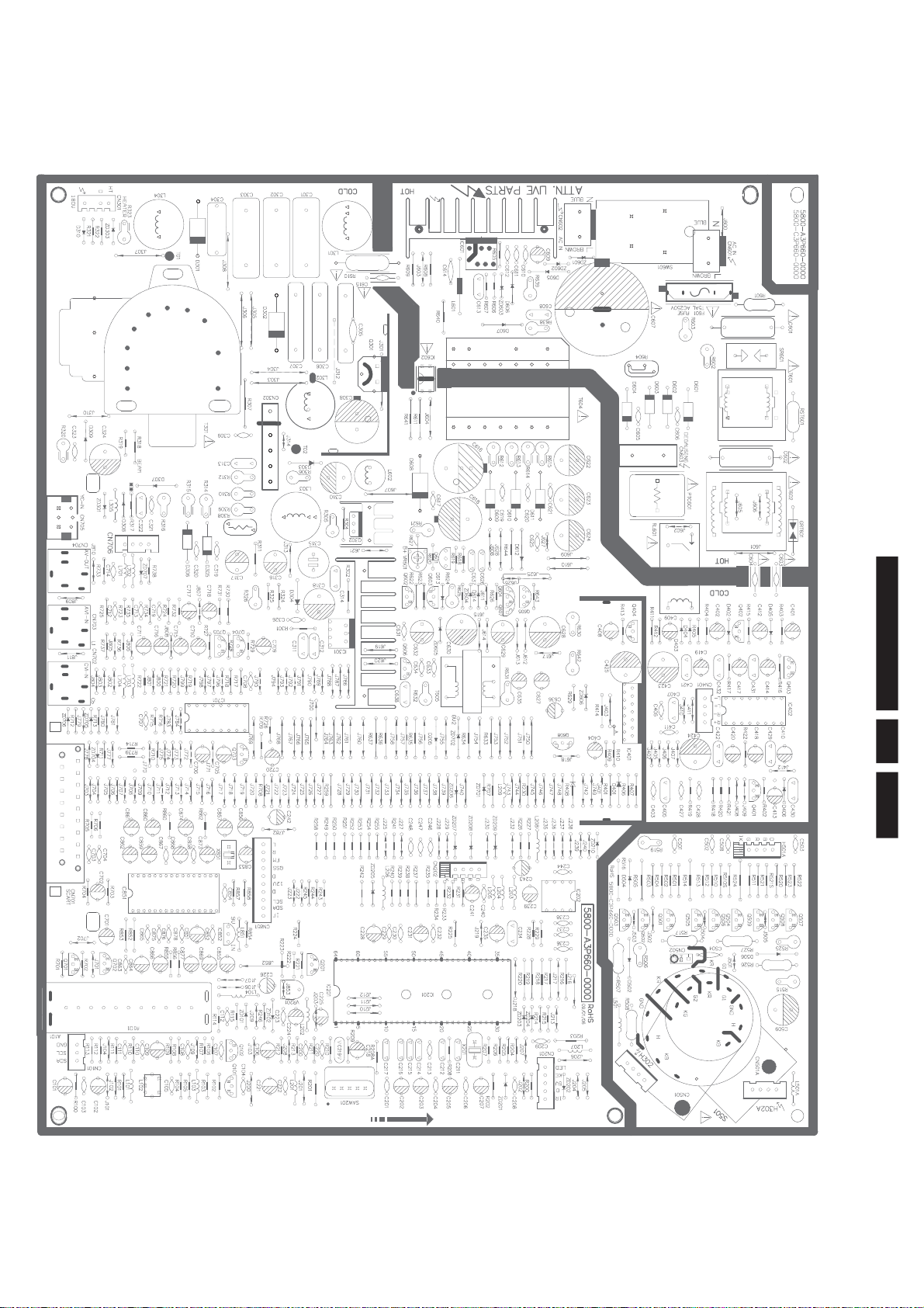
Main PCB (Top Side)
Circuit Diagrams and PWB Layouts
3P66
6.
E26
N
Page 28
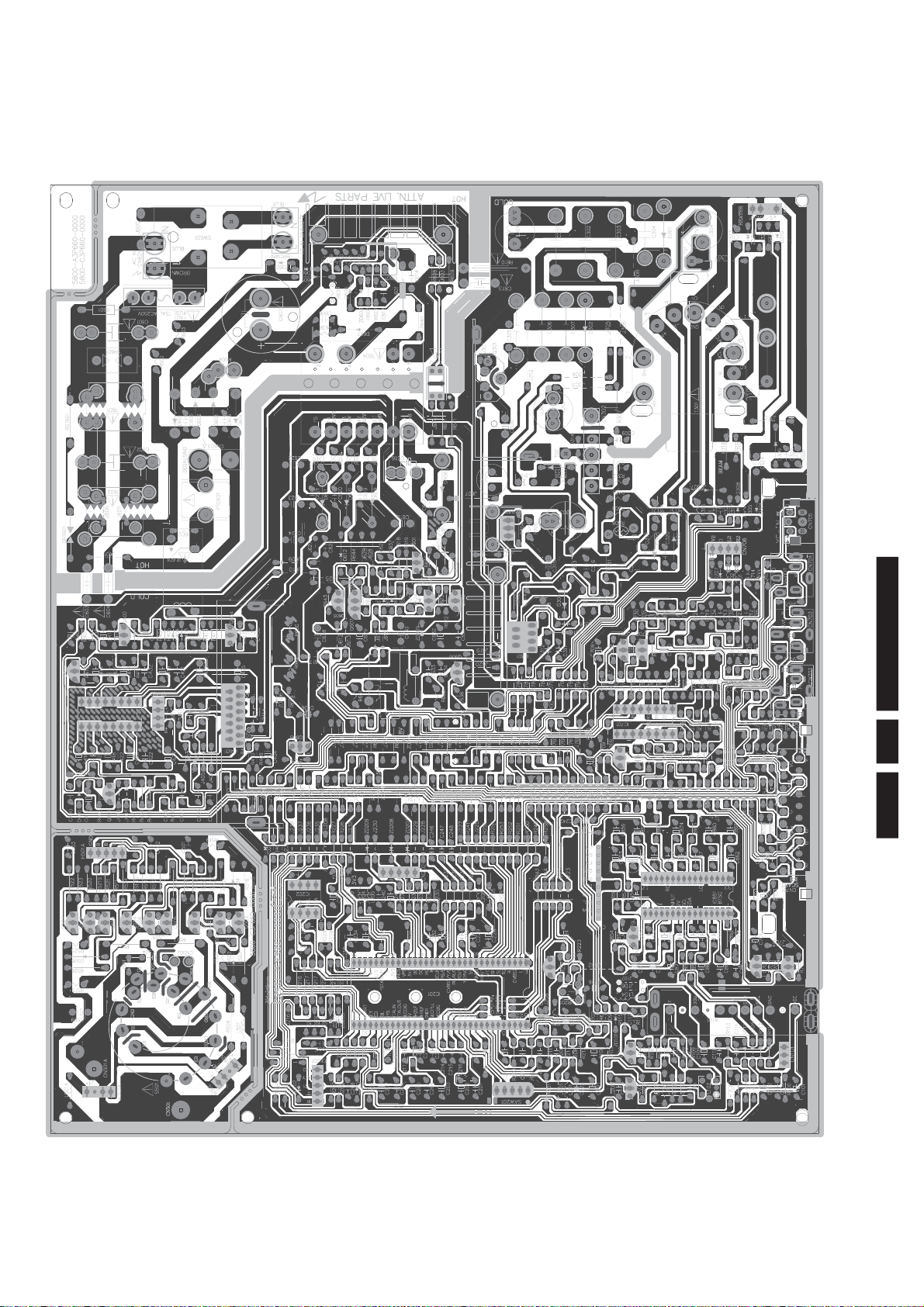
Main PCB (Bottom Side)
Circuit Diagrams and PWB Layouts
3P66
6.
E27
N
Page 29
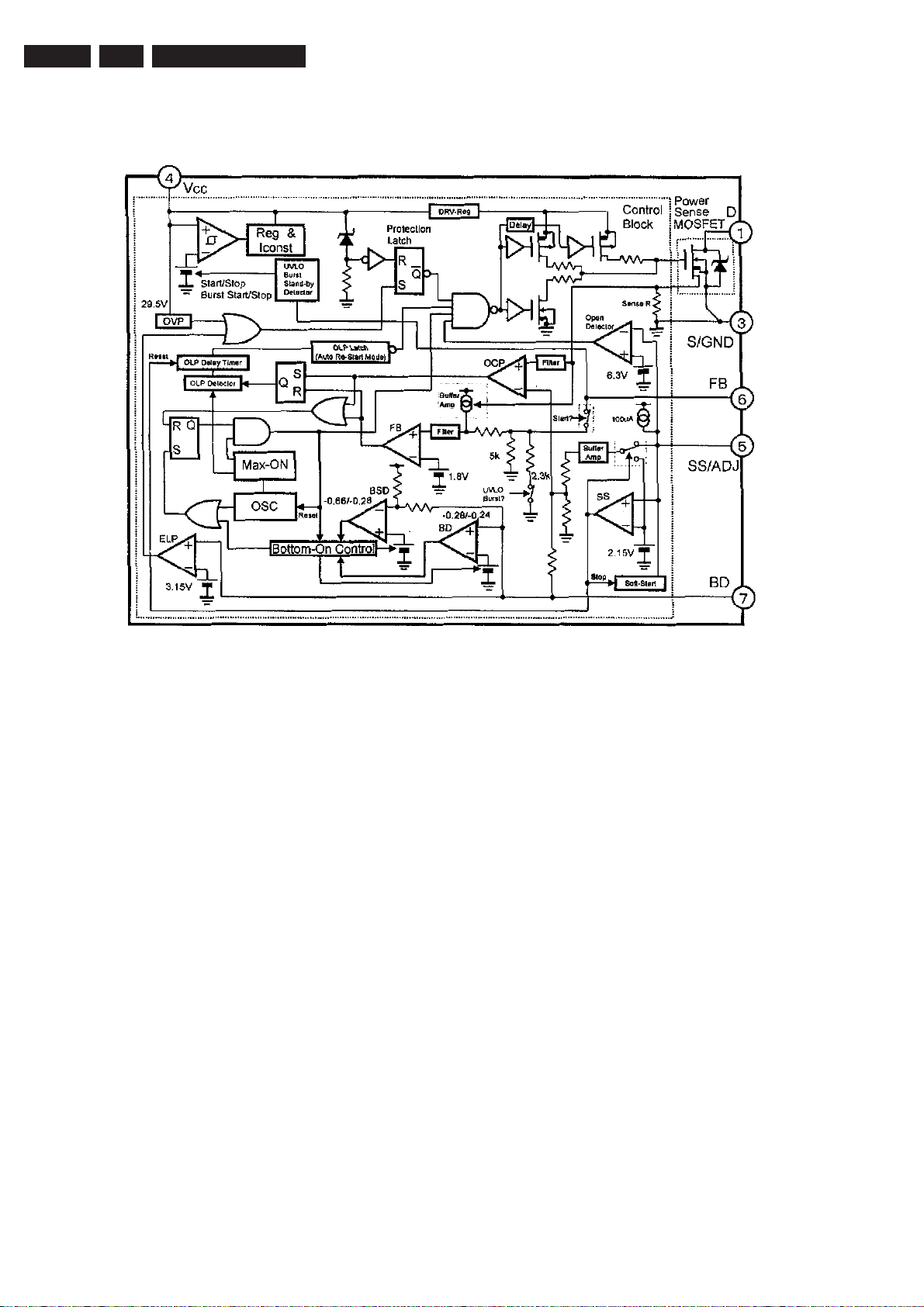
EN 28
7.
3P66
IC601(POWER SUPPLY)STR-W6554A
Block Diagram:
IC Data Sheet
Page 30
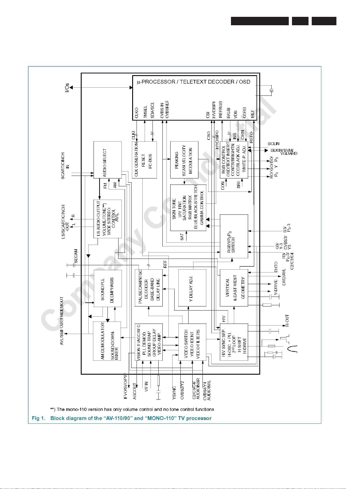
IC Data Sheet
IC101(OTP SIGNAL PROCESSOR FOR CRT TV)TDA11106PS N3
Block Diagram:
3P66
7.
EN 29
Page 31
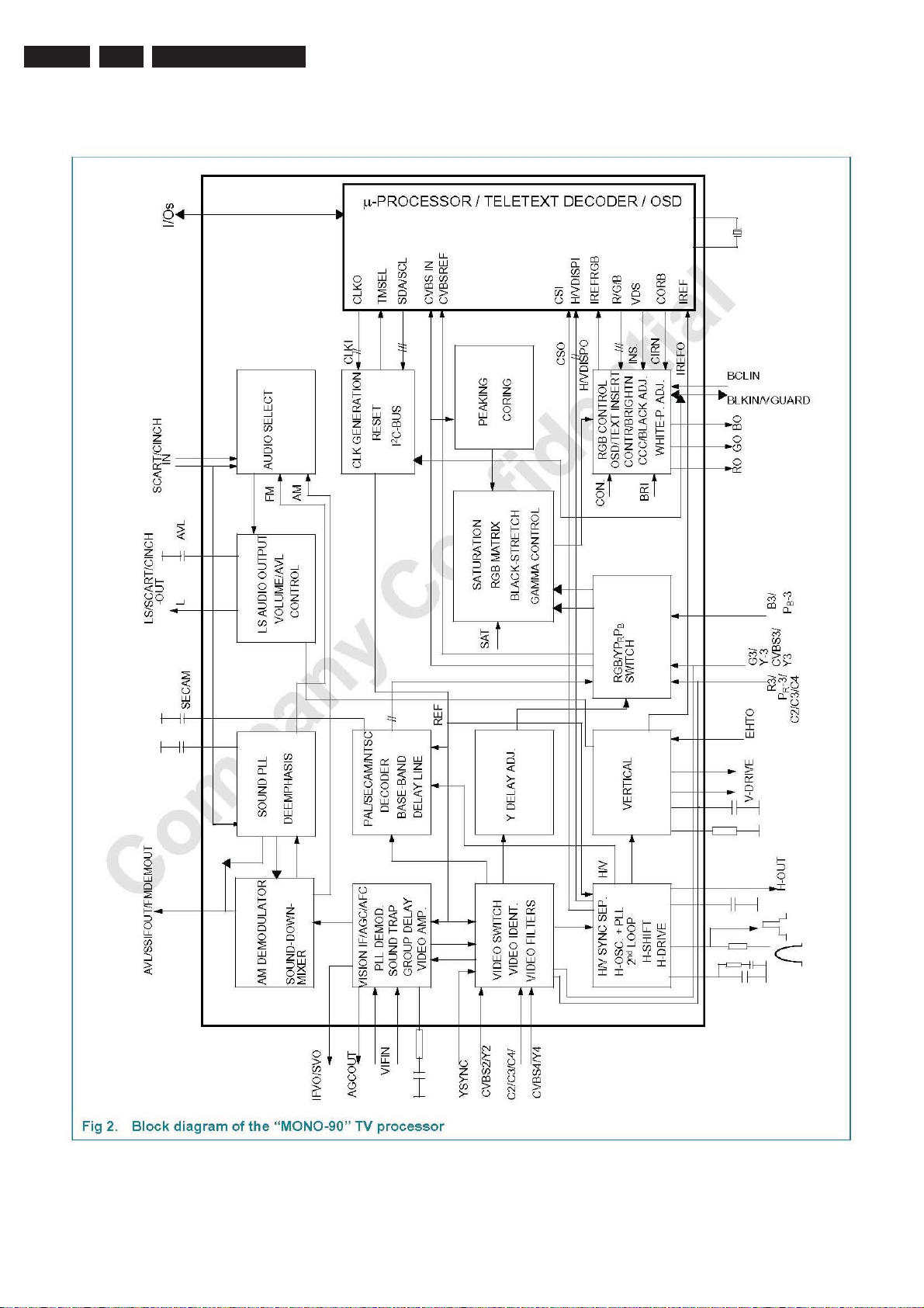
EN 30
7.
3P66
IC Data Sheet
Page 32
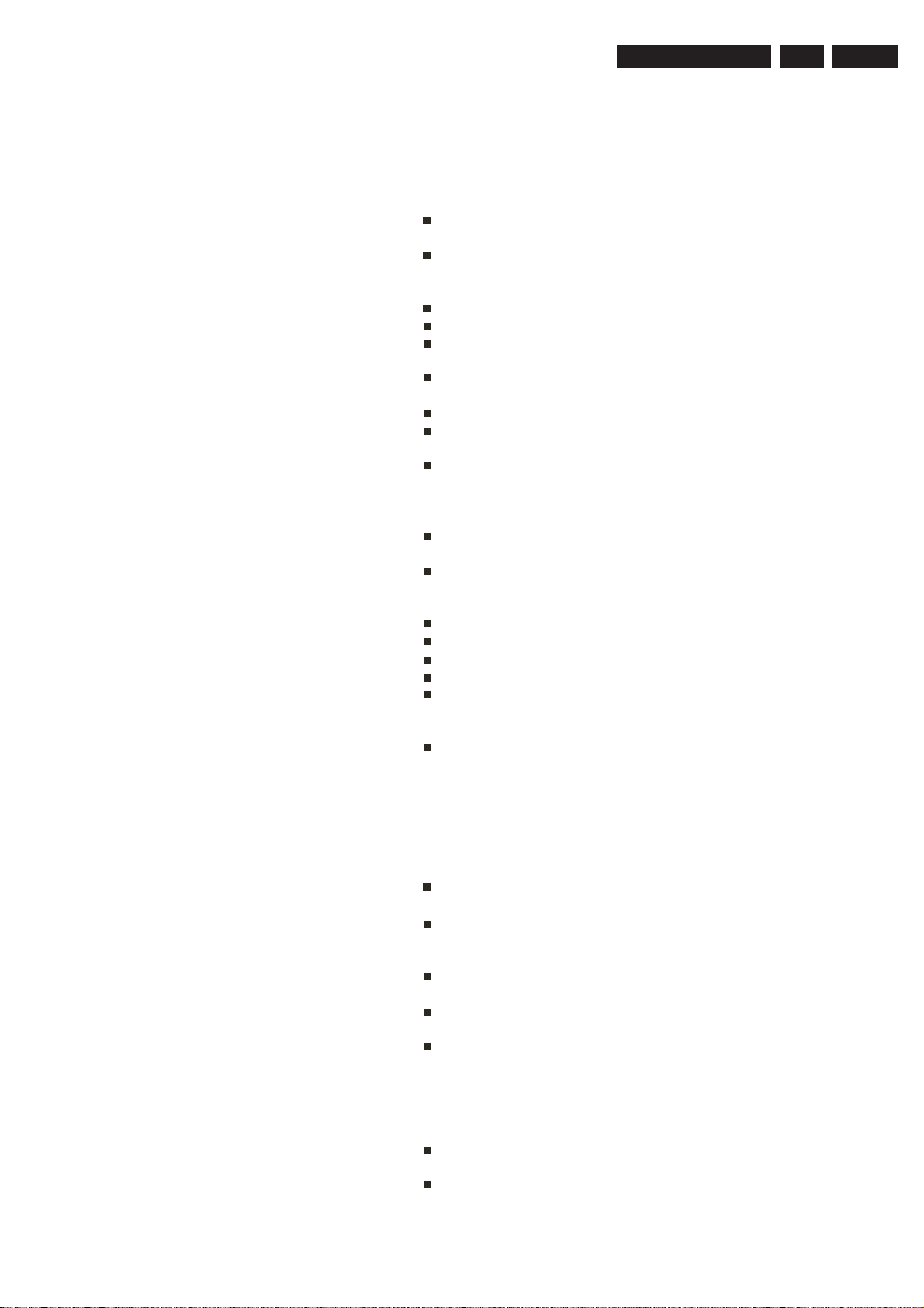
Troubleshooting
3P66
8.Troubleshooting
The following problems do not always indicate a hardware failure. Therefore, please use the
guide
before calling for repair service. If, after following the
service.
Problem Checks and Adjustments
none of the remedies work, unplug the TV and call for
8.
troubleshooting guide below
EN 31
TV will not turn on
No picture, no sound
No sound, picture OK
Spots on the screen (Snow)
Poor reception of broadcast
channels
Make sure the power cord is plugged in,
then press POWER button.
Check battery in the remote control.
(Maybe batteries are dead.)
Ensure the TV power is ON .
Check antenna/ cable connections.
Try different channel.
Maybe sound is muted. Try pressing
VOL+ button is not set to minimum.
Try another channel.
Check the AV cables for disconnection.
Maybe the TV is being affected by
interference from automobiles, trains,
high-voltage transmission lines, neon
signs or another sources of interference.
Try redirecting or relocating your antenna
to reduce the affects of the interference.
Change channels to confirm if the
symptom is still present.
Try another channel.
Check antenna connections.
If using VCR, check TV/VCR button.
Adjust fine tuning control.
Probably local interference, such as an
appliance.
VCR
Cannot select a certain channel
Remote Control does not operate
The picture is doubled or tripled
(GHOST)
Degraded colours or tints
When the VCR test signal (TSG) is
received, the lower side of the test
pattern is distorted as shown in the
figure. This is not a malfunction and the
playback picture is not influenced by it.
That channel may be locked out with
SKIP CHANNEL function.
Check for any obstacle between the
remote control and the remote control
sensor window .
Maybe batteries are dead. Try replacing
batteries with new ones.
Check for incorrect battery orientation.
Please change the direction, height or
positionof the antenna. Reflections from
building or mountains might cause this
phenomenon. A highly directional
antenna may improve the reception.
Check whether all the picture adjustments
have been properly performed.
Enter into the (Picture mode) inside the
menu to select a different picture set-up.
 Loading...