

Page 1
Global LCD Panel Exchange Center
TFT-LCD Perliminary Specification
www.panelook.com
Issue Date: Aug.15.2000
Model: N141X3
Preliminary
Model No: N141X3
Liquid Crystal Division
QRA Dept. RD Dept. System Dept.
Approval Approval Approval
1/18
This technical specification is preliminary and it will be changed without notice Please contact
CMO’s representative while your product design is base on this specification. Version 1.0
One step solution for LCD / PDP / OLED panel application: Datasheet, inventory and accessory!
www.panelook.com
Page 2
Global LCD Panel Exchange Center
CONTENTS
REVISION HISTORY
www.panelook.com
Issue Date: Aug.15.2000
Model: N141X3
Preliminary
GENERAL DESCRIPTION
1. ABSOLUTE MAXIMUM RATINGS
2. ELECTRICAL SPECIFICATIONS
3. BLOCK DIAGRAM
4. INTERFACE SPECIFICATIONS
4.1 THE PIN ASSIGNMENT OF INTERFACE CONNECTOR
4.2 INPUT SIGNAL TIMING SPECIFICATIONS
4.3 COLOR DATA INPUT ASSIGNMENT
4.4 POWER UP/DOWN SEQUENCE
5. OPTICAL SPECIFICATIONS
6. MECHNICAL DRAWINGS
7. PRECAUTION
7.1 ASSEMBLY AND HANDLING PRECAUTION
7.2 SAFTY PRECAUTION
2/18
This technical specification is preliminary and it will be changed without notice Please contact
CMO’s representative while your product design is base on this specification. Version 1.0
One step solution for LCD / PDP / OLED panel application: Datasheet, inventory and accessory!
www.panelook.com
Page 3
Global LCD Panel Exchange Center
VERSION Date DESCPIPTION
Ver 0.1
Ver 1.0
Jun.29,’00
Aug.15,’00
www.panelook.com
Issue Date: Aug.15.2000
Model: N141X3
Preliminary
REVISION HISTORY
Issue Tentative specification.
Issue Preliminary specification.
Page 4/18
- Update FEATURES.
- Change Module Size
Page 5/18
- Change Humidity
Page 6/18
- Change ELECTRICAL SPECIFICATIONS.
Page 6/18~8/18
- Add Note(1)~Note(8)
Page 9/18
- Add 3. BLOCK DIAGRAM
Page 11/18
- Add 4.2 INPUT SIGNAL TIMING SPECIFICATIONS
Page 12/18
- Change INPUT SIGNAL TIMING DIAGRAM.
Page 14/18
- Revise Timing Specifications on 4.4 POWER UP/DOWN
Page 15/18
- Change 5. OPTICAL SPECIFICATIONS.
Page 17/18
- Add 7. PRECAUTION
Depth: old: 5.8mm(Typ.) / 6.1mm(Max.)
new: 5.7mm(Typ.) / 6.0mm(Max.)
Weight: old: 600mm(Typ.) / -(Max.)
new: 510mm(Typ.) / 530mm(Max.)
Old: ≤95% relative humidity/40°C≤Ta≤50°C
New: ≤85% relative humidity/40°C≤Ta ≤50°C
“H” level LVDS signal input: old: -100(Min.)/ -(Typ.)/ -(Max.)
new: -(Min.)/ -(Typ.)/+100(Max.)
“L” level LVDS signal input: old: -(Min.)/ -(Typ.)/ 100(Max.)
new: -100(Min.)/ -(Typ.)/ -(Max.)
Power Supply Current: old:-(Max.) new: TBD(Max.)
Rush Current: old: 1.6(Typ.)/ 1.8(Max.)
new: (1.6)(Typ.)/ (1.8)(Max.)
SEQUENCE.
Old:t4≥1S new:t4≥0.7S
Average Luminance:
old: -(Typ.)/(150)(Max.)new:(150)(Typ.)/- (Max.)
Falling of Response Time: old: (25)(Typ.) new: (35)(Typ.)
Chromaticity:
Xw: old: (0.307)(Typ.)/-(Max.) new: -(Typ.)/(0.31)(Max.)
Yw: old: (0.337)(Typ.)/-(Max.) new: -(Typ.)/(0.33)(Max.)
3/18
This technical specification is preliminary and it will be changed without notice Please contact
CMO’s representative while your product design is base on this specification. Version 1.0
One step solution for LCD / PDP / OLED panel application: Datasheet, inventory and accessory!
www.panelook.com
Page 4
Global LCD Panel Exchange Center
www.panelook.com
Issue Date: Aug.15.2000
Model: N141X3
Preliminary
GENERAL DESCRIPTION
OVERVIEW
This product is a 14.1” TFT Liquid Crystal Display Module with a Backlight unit and 20 pins
LVDS (Low Voltage Differential Signal) interface. This module supports 1024 x 768 XGA
mode and can display 262,144 colors. The inverter module for Backlight is not built in.
FEATURES
-XGA (1024x768 pixels) resolution
-1 CCFLs (Cold Cathode Fluorescent Lamp)
-DE only Mode / Standard Mode
-LVDS (Low Voltage Differential Signaling) Interface
APPLICATION
-Note Book PC
GENERAL SPECIFICATI0NS
Item Specifications Unit
Screen Size 14.1 Diagonal inch
Bezel opening area 288.8(W)x217.4(H) mm
Effective display area 285.7(W)x214.3(H) mm
Pixel number 1024 x R.G.Bx768 pixel
Pixel pitch 0.279(H)x0.279(V) mm
Pixel Arrangement R.G.B Vertical Stripe Display Color 6 bits, 262,144 color
Transmissive mode Normally white Surface treatments Hard coating(3H) and anti-glare (Haze 12) -
MECHANICAL SPECIFICATIONS
ITEM MIN. TYP. MAX. Unit
Module
size
Horizontal 298 298.5 299 mm
Vertical 227 227.5 228 mm
Depth - 5.7 6.0 mm
Weight - 510 530 g
4/18
This technical specification is preliminary and it will be changed without notice Please contact
CMO’s representative while your product design is base on this specification. Version 1.0
One step solution for LCD / PDP / OLED panel application: Datasheet, inventory and accessory!
www.panelook.com
Page 5
Global LCD Panel Exchange Center
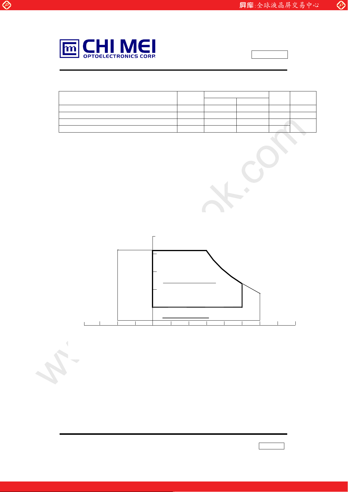
1. ABSOLUTE MAXIMUM RATINGS
1.1 ABSOLUTE RATINGS OF ENVIRONMENT
Item Symbol
Storage temperature Tst -20 +60 ºC (1)
Operating temperature (Ambient Temperature) Top 0 +50 ºC (1)
Shock(non-operating) Snop - 30 G
Vibration(non-operating) Vnop - 1.5 G
Note (1) Temperature and relative humidity range is shown in the figure below.
85% RH Max. (40ºC Ta )
Maximum wet-bulb temperature at 39ºC or less. (Ta > 40ºC) No condensation.
Note (2) 6ms, sine wave, one time for ± X, ± Y, ± Z.
Note (3) 10-500 Hz, Sweep rate 20min, 60min for X, Y, Z.
Note (4) At testing Vibration and Shock, the fixture in holding the Module to be tested has to
be hard and rigid enough so that the Module would not be twisted or bent by the fixture.
-40
-20 40020
www.panelook.com
Relative Humidity (%RH)
100
85
80
60
Operating Range
40
20
5
Temperature (ºC)
Storage Range
Issue Date: Aug.15.2000
Model: N141X3
Preliminary
Valu es
Min. Max.
Unit Note
(2),(4)
(3),(4)
8060
5/18
This technical specification is preliminary and it will be changed without notice Please contact
CMO’s representative while your product design is base on this specification. Version 1.0
One step solution for LCD / PDP / OLED panel application: Datasheet, inventory and accessory!
www.panelook.com
Page 6
Global LCD Panel Exchange Center
2. ELECTRICAL SPECIFICATIONS
2.1 TFT LCD MODULE
Parameter Symbol
Power Supply Voltage VCC 3.0 3.3 3.6 V
“H” level LVDS signal input VIH - - +100 mV
“L” level LVDS signal input VIL -100 - - mV
Power Supply Current l
Rush Current IRUSH - (1.6) (1.8) A (8)
Ripple voltage VRP - 50 - mV
Terminating resistor Rt - 100 - Ohm
2.2 BACKLIGHT UNIT
Parameter Symbol
Lamp Voltage VL - 630 - V
Lamp Current IL 4.0 6.0 7.0 mA (2)
Startup Voltage VS
Operating Frequency
Power Consumption
Lamp Life time LBL 12000 20000 - Hrs (6)
Pin Symbol Description Remark
1 HV Lamp power input White
2 LV Ground Black
Connector Part No.: BHSR-02VS-1(JST)
User’s connector Part No.: SM02B-BHSS-1-TB (JST)
Note(1) The operating temperature range is 0 ~ 50 ºC, and the typical value of Power
Supply
Current is measured in black pattern.
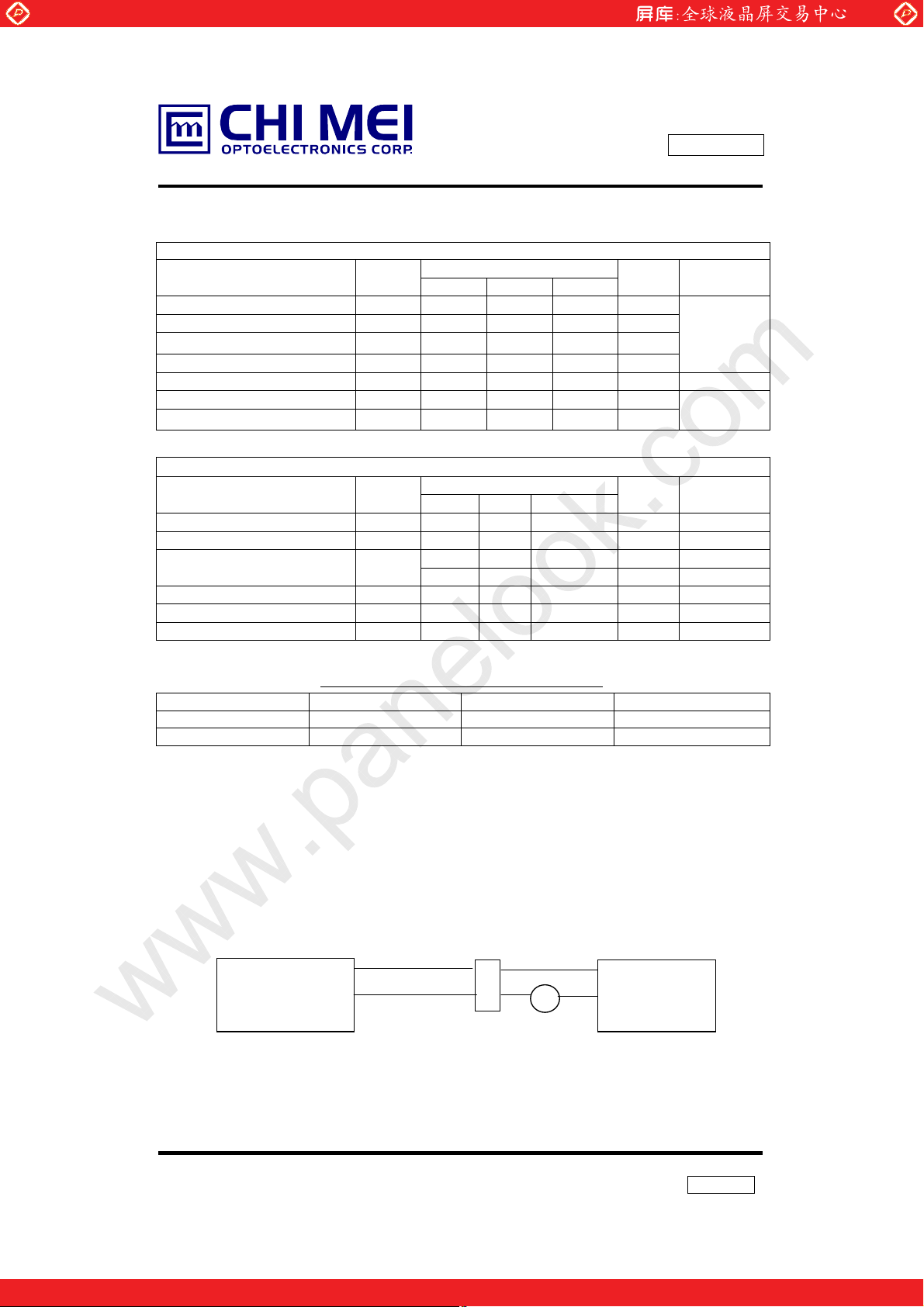
Note(2) Lamp current is measured by utilizing a current meter for high frequency as shown
below:
LCD
Module
Note(3) The voltage shown above should be applied to the lamp for more than 1 second after
startup. Otherwise the lamp may not be turned on.
www.panelook.com
MODULE
Valu e
Min. Typ. Max.
- 400 TBD mA
CC
BACKLIGHT ( 1 Lamp) Ta=252к
Valu e
Min. Typ. Max.
- - 975 V
- - 1170 V
F
40 55 70 KHz (4)
L
P
- 4.2 - W (5), IL=6.0mA
L
The connector information of Back light unit.
Hot(Whit
GND(Black)
e)
1
2
(Yokogawa Y2016)
A
Current meter
Issue Date: Aug.15.2000
Model: N141X3
Preliminary
Unit Notes
(1)
(1)
Unit Notes
IL=6.0mA
RMS
(25oC)
RMS
(0 oC)
RMS
Inverter
6/18
This technical specification is preliminary and it will be changed without notice Please contact
CMO’s representative while your product design is base on this specification. Version 1.0
One step solution for LCD / PDP / OLED panel application: Datasheet, inventory and accessory!
www.panelook.com
Page 7

Global LCD Panel Exchange Center
Note(4) The lamp frequency may produce interference with horizontal synchronous frequency
from the display, and this may cause line flow on the display. In order to avoid
interference the lamp frequency should be detached from the horizontal synchronous
frequency and its harmonics as far as possible.
.
Note(5) P
Note(6) The lifetime (Hr) of a lamp can be defined as the time in which it continues to operate
under the condition Ta = 252к and I
occurs:
Note(7) The waveform of the voltage output of inverter must be area-symmetric and the
design
of the inverter must have specifications for the modularized lamp. The performance of
the backlight, such as lifetime or brightness, is greatly influenced by the
characteristics
L
= I
.
V
L
L
(1) When the brightness becomes 50% or lower than its original,
(2) When the effective ignition length becomes 80% or lower than its original value.
(Effective ignition length is defined as an area that has less than 70% brightness
compared to the brightness in the center point.)
of the DC-AC inverter for the lamp. All the parameters of an inverter should be
designed with care so as not to produce too much current leakage from high-voltage
output of the inverter. When designing or ordering the inverter, please make sure that
a poor lighting caused by the mismatch of the backlight and the inverter (miss-lighting,
flicker, etc.) never occurs. When the above situation is confirmed, the module should
be operated in the same manners as it is installed in your instrument.
www.panelook.com
= 6.0 mArms until one of the following event
L
Issue Date: Aug.15.2000
Model: N141X3
Preliminary
7/18
This technical specification is preliminary and it will be changed without notice Please contact
CMO’s representative while your product design is base on this specification. Version 1.0
One step solution for LCD / PDP / OLED panel application: Datasheet, inventory and accessory!
www.panelook.com
Page 8

Global LCD Panel Exchange Center
Note(8) Rush current measurement condition
www.panelook.com
Issue Date: Aug.15.2000
Model: N141X3
Preliminary
M1:2SK1475
M2:2SK1470
The circuit above produces a power Vcc with TBD rising time.
GND
TBD
0.9VCC
3.3V
8/18
This technical specification is preliminary and it will be changed without notice Please contact
CMO’s representative while your product design is base on this specification. Version 1.0
One step solution for LCD / PDP / OLED panel application: Datasheet, inventory and accessory!
www.panelook.com
Page 9

Global LCD Panel Exchange Center
p
(
)
3. BLOCK DIAGRAM
BLOCK DIAGRAM
Rxin0(+/-)
Rxin1(+/-)
Rxin2(+/-)
In
ut Connector
CLK(+/-)
Vcc
Vcc
(Option)STMD
GND
JAE-FI-SEB20P-HF
VL
Lamp Connector
( JST-BHSR-02VS-1)
www.panelook.com
Timing Control
ASIC (LVDS
embeded)
DC/DC Converter
& Reference
Voltage Generator
Issue Date: Aug.15.2000
Model: N141X3
Preliminary
Scan Driver IC
TFT-LCD Panel
(1024x768x3)
Data Driver IC
Backlight Unit
9/18
This technical specification is preliminary and it will be changed without notice Please contact
One step solution for LCD / PDP / OLED panel application: Datasheet, inventory and accessory!
CMO’s representative while your product design is base on this specification. Version 1.0
www.panelook.com
Page 10

Global LCD Panel Exchange Center
4. INTERFACE SPECIFICATIONS
4.1 THE PIN ASSIGNMENT OF INTERFACE CONNECTOR.
Pin Symbol Description Notes
1 VCC Power supply +3.3 v
2 VCC Power supply +3.3 v
3 Vss Ground
4 Vss Ground
5 Rxin0- LVDS differential data input (Negative)
6 Rxin0+ LVDS differential data input (Positive)
7 Vss Ground
8 Rxin1- LVDS differential data input (Negative)
9 Rxin1+ LVDS differential data input (Positive)
10 Vss Ground
11 Rxin2- LVDS differential data input (Negative)
12 Rxin2+ LVDS differential data input (Positive)
13 Vss Ground
14 CLK- LVDS Clock Data input (Negative)
15 CLK+ LVDS Clock Data input (Postive)
16 Vss Ground
17 NC Non-connection
18 STMD Standard mode selection See Section 4.2
19 Vss Ground
20 Vss Ground
Connector Part No.: FI-SEB20P-HF13R (JAE) or Equivalent
User’s connector Part No: FI-S20S or FI-SE20M (JAE)
www.panelook.com
Issue Date: Aug.15.2000
Model: N141X3
Preliminary
R0~R5,G0
G1~G5,B0,B1
B2~B5,DE,Hsync,
Vsync
LVDS level
10/18
This technical specification is preliminary and it will be changed without notice Please contact
CMO’s representative while your product design is base on this specification. Version 1.0
One step solution for LCD / PDP / OLED panel application: Datasheet, inventory and accessory!
www.panelook.com
Page 11

Global LCD Panel Exchange Center
4.2 INPUT SIGNAL TIMING SPECIFICATIONS
The specifications of input signal timing are as the following table and timing diagram.
Signal Parameter Symbol Min Typ Max Unit Remarks
DCLK Pixel clock period Tck - 15 - ns
a.) DE Only Mode
If ‘Pin 18’ is left open or pulled high, DE mode is selected. When N141X3 is working under DE
mode, the signals, VSYNC and HSYNC, are ignored. All timing of timing controller is driven
from DE signal.
VSYNC
HSYNC
b.) Standard Mode
If ‘Pin 18’ is pulled down, Standard mode is selected. When Standard mode is used, VSYNC,
HSYNC and DE should be provided.
VSYNC
HSYNC
Vertical period Tvp 777 806 834 Thp
Vertical display blank period
Vertical display active period
Vertical sync. back porch Vbp 0 29 65 Thp
Vertical sync. front porch Vfp 0 3 65 Thp
Vertical sync. pulse width Vpw 1 6 66 Thp
Horizontal period Thp 1342 1344 1356 Tck Need to be
Horizontal display blank period
Horizontal display active
period
Horizontal sync. back porch
Horizontal sync. front porch
Horizontal sync. pulse width Hpw 1 136 308 Tck
Vertical period Tvp 769 806 1000 Thp
Vertical display blank period
Vertical display active period
Vertical sync. back porch Vbp 0 29 231 Thp
Vertical sync. front porch Vfp 0 3 231 Thp
Vertical sync. pulse width Vpw 1 6 232 Thp
Horizontal period Thp 1100 1344 1612 Tck Need to be
Horizontal display blank period
Horizontal display active
period
Horizontal sync. back porch
Horizontal sync. front porch
Horizontal sync. pulse width Hpw 24 136 578 Tck
www.panelook.com
Tvdb 9 38 66 Thp
Tvda 768 768 768 Thp
Thdb 318 320 332 Tck
Thda 1024 1024 1024 Tck
Hbp 24 160 331 Tck
Hfb 0 24 307 Tck
Tvdb 1 38 232 Thp
Tvda 768 768 768 Thp
Thdb 76 320 588 Tck
Thda 1024 1024 1024 Tck
Hbp 10 160 564 Tck
Hfb 0 24 554 Tck
Issue Date: Aug.15.2000
Model: N141X3
Preliminary
T
vdb=Tpw+Tbp
T
hdb=Hpw+Hb
T
vdb=Tpw+Tbp
T
hdb=Hpw+Hb
+Tfp
even
+Hfp
p
+Tfp
even
+Hfp
p
11/18
This technical specification is preliminary and it will be changed without notice Please contact
CMO’s representative while your product design is base on this specification. Version 1.0
One step solution for LCD / PDP / OLED panel application: Datasheet, inventory and accessory!
www.panelook.com
Page 12

Global LCD Panel Exchange Center
VSYNC
www.panelook.com
Issue Date: Aug.15.2000
Model: N141X3
Preliminary
INPUT SIGNAL TIMING DIAGRAM
Vpw
HSYNC
DE
HSYNC
DE
DCLK
768
T
Hpw
Thdb
vdb
Vbp
Tvp
1
Hbp
Tvda
2
Thp
Thda
Vfp
768
Hfp
DATA
This technical specification is preliminary and it will be changed without notice Please contact
CMO’s representative while your product design is base on this specification. Version 1.0
Valid display data (1024 Tck)
12/18
Invalid
One step solution for LCD / PDP / OLED panel application: Datasheet, inventory and accessory!
www.panelook.com
Page 13

Global LCD Panel Exchange Center
4.3 COLOR DATA INPUT ASSIGNMENT
www.panelook.com
Issue Date: Aug.15.2000
Model: N141X3
Preliminary
Basic
Colors
Gray
Scale
Of
Red
Gray
Scale
Of
Green
Gray
Scale
Of
Blue
Color
Black
Red
Green
Blue
Cyan
Magenta
Yellow
White
Red(0) / Dark
Red(1)
Red(2)
Red(61)
Red(62)
Red(63)
Green(0) / Dark
Green(1)
Green(2)
Green(61)
Green(62)
Green(63)
Blue(0) / Dark
Blue(1)
Blue(2)
Blue(61)
Blue(62)
Blue(63)
Data Signal
R5 R4 R3 R2 R1 R0 G5 G4 G3 G2 G1 G0 B5 B4 B3 B2 B1 B0
0
1
0
0
0
1
1
1
0
0
0
:
:
:
:
:
:
:
:
1
1
1
0
0
0
:
:
0
0
0
0
0
0
:
:
0
0
0
Red Green Blue
0
0
1
0
0
0
1
1
1
0
0
0
:
:
1
1
1
0
0
0
:
:
0
0
0
0
0
0
:
:
0
0
0
0
0
0
0
0
0
0
0
0
0
0
1
1
1
1
0
0
0
1
1
1
1
1
1
0
0
0
0
1
1
1
0
0
0
0
0
0
0
0
0
0
1
1
1
1
1
1
1
1
1
0
0
0
0
1
1
1
0
0
0
0
0
0
1
1
1
1
0
0
0
1
1
1
1
1
1
1
1
1
1
1
1
1
1
1
1
1
1
1
1
1
0
0
0
0
0
0
0
0
0
0
0
0
0
0
1
0
0
:
:
1
1
1
0
0
0
:
:
0
0
0
0
0
0
:
:
0
0
0
0
0
0
0
0
0
0
0
1
0
:
:
:
:
:
:
:
:
:
:
:
:
:
:
:
:
0
0
0
0
0
1
0
1
0
0
0
0
0
0
1
1
0
0
0
0
0
1
1
1
0
0
0
0
0
0
0
0
0
0
0
0
0
0
0
0
0
0
:
:
:
:
:
:
:
:
:
:
:
:
1
1
1
0
0
0
1
1
0
0
0
1
0
0
0
0
0
0
0
0
0
0
0
0
0
0
0
:
:
:
:
:
:
:
:
0
0
0
0
0
0
0
0
0
0
0
0
1
1
1
0
0
0
0
0
0
:
:
:
:
0
0
0
0
0
0
0
0
0
0
1
0
:
:
:
:
0
1
1
1
1
1
0
0
0
0
0
0
:
:
:
:
0
0
0
0
0
0
1
0
0
0
0
0
0
:
:
:
:
0
0
0
0
0
0
0
0
1
0
0
0
:
:
:
:
1
0
0
0
0
1
0
0
0
0
0
0
:
:
:
:
1
0
1
0
1
0
1
0
0
0
0
0
0
:
:
:
:
0
0
0
0
0
0
0
0
0
0
0
0
:
:
:
:
0
0
0
0
0
0
0
0
0
0
0
0
:
:
:
:
1
1
1
1
1
1
0
0
0
0
0
0
0
0
0
0
0
0
0
0
0
0
1
1
1
0
1
0
0
0
:
:
0
0
0
0
0
0
:
:
0
0
0
0
0
0
:
:
1
1
1
0
0
0
1
1
1
1
1
1
0
0
1
1
0
0
0
0
0
0
:
:
:
:
0
0
0
0
0
0
0
0
0
0
0
0
:
:
:
:
0
0
0
0
0
0
0
0
1
0
0
1
:
:
:
:
1
0
0
1
1
1
13/18
This technical specification is preliminary and it will be changed without notice Please contact
CMO’s representative while your product design is base on this specification. Version 1.0
One step solution for LCD / PDP / OLED panel application: Datasheet, inventory and accessory!
www.panelook.com
Page 14

Global LCD Panel Exchange Center
4.4 POWER UP/DOWN SEQUENCE
Vcc
0V
Signals
0V
CCFL
Timing Specifications:
0 Љ t1 Љ 10mS
0 Љ t2 Љ 50mS
0 Љ t3 Љ 50mS
t4 Њ 0.7S
t5 Њ 170mS
t6 Њ 200mS (min.)
90%
10%
t1
www.panelook.com
t2
t5
90%
t6
t3
Issue Date: Aug.15.2000
Model: N141X3
Preliminary
t4
10%
10%
Notes: 1. Please avoid floating state of interface signal at invalid period.
2. When the interface signal is invalid, be sure to pull down the power supply for
LCD Vcc to 0V.
14/18
This technical specification is preliminary and it will be changed without notice Please contact
CMO’s representative while your product design is base on this specification. Version 1.0
One step solution for LCD / PDP / OLED panel application: Datasheet, inventory and accessory!
www.panelook.com
Page 15

Global LCD Panel Exchange Center
5. OPTICAL SPECIFICATIONS
The following optical specifications shall be measured in a dark room or equivalent state
(ambient luminance ≤1 lux, and at room temperature). The measurement must be taken after
backlight warming up for 20 minutes. The operation temperature is 25°C ± 2°C. The
measurement method is shown in Note 1.
Parameter Symbol Condition Min. Typ. Max. Unit Note
Luminance L
Brightness Uniformity Buni
Contrast Ratio CR Center - (150) - - (1),(4)
Horizontal
Viewing Angle
Ver tical
Response Time
Chromaticity
Note(1) The method of optical measurement:
Rising Tr - (15) (30) ms
Falling Tf
www.panelook.com
Issue Date: Aug.15.2000
Model: N141X3
Preliminary
I
=5.0mA
L
ave
I
=6.0mA
θx+
θ
x-
θy+
θy-
L
θ
x =θy = 0
Center
CR ≥10
Center
CR ≥10
Center
θx =θy = 0
o
o
XW (0.31)
YW (0.33)
XR (0.58)
Center
YR (0.35)
θx =θy = 0
XG (0.32)
o
YG (0.54)
XB (0.15)
Y
B
Photodetector
(TOPCON BM-5A)
50 cm
Field=2
º
- (130) - cd/m2 (1),(2)
- (150) - cd/m2 (1),(2)
- (1.4) (1.6) (1),(3)
(40) (45) (40) (45) (10) (15) -
Degree (4),(5)
(30) (35) -
- (35) (50) ms
(1),(6)
(1),(7)
(0.14)
TFT-LCD Module
15/18
This technical specification is preliminary and it will be changed without notice Please contact
CMO’s representative while your product design is base on this specification. Version 1.0
One step solution for LCD / PDP / OLED panel application: Datasheet, inventory and accessory!
www.panelook.com
Page 16

Global LCD Panel Exchange Center
Note(2) Definition of Luminance (Lave):
Luminance should be measured the luminance of gray level 63 ( L 63 )at the 5 points
of the LCD module and at the viewing angle of the θx
Vertical Line number [pixel]
Note(3) Definition of Brightness Uniformity (Buni):
(Note 2).
Buni =
Note(4) Definition of Contrast Ratio (CR):
The contrast ratio can be calculated by the following expression.
Contrast Ratio (CR) = L63 / L0
L63 : Luminance on the white raster (gray level 63)
L 0 : Luminance on the black raster (gray level 0)
Lave =
0 255 511 767 1023
0
191
383
575
767
Maximum luminance of 5 points
Minimum luminance of 5 points
www.panelook.com
= θy = 0
L(1) + L(2) + L(3) + L(4) + L(5)
5
2
1
4
Active area
Horizontal Line number [pixel]
Issue Date: Aug.15.2000
Model: N141X3
Preliminary
o
.
: test point
x
3
5
CR
= CR(1)
CR(x) is corresponding to the Contrast Ratio of a point x at Figure Note 2.
16/18
This technical specification is preliminary and it will be changed without notice Please contact
CMO’s representative while your product design is base on this specification. Version 1.0
One step solution for LCD / PDP / OLED panel application: Datasheet, inventory and accessory!
www.panelook.com
Page 17

Global LCD Panel Exchange Center
Note(5) Definitions of Viewing Angle (CR ≥ 10):
6 o’clock
y-
θ
100%
10%
θX- = 90º
= 90º
White L63
90%
0%
Note(6) Definition of Response Time:
The Response Time is set initially by defining the “ Rising Time (Tr)” and the “ Falling
Time (Tf)” respectively. Tr and Tf are defined as following figure.
Data input
Note(7) Definition of Chromaticity:
The color coordinates (Xw, Yw), (X
pixels in the viewing field at white, red, green, and blue states, respectively.
y-
x-
www.panelook.com
Normal
θ
x = θy = 0º
θy- θy+
θx−
θx+
Tr
R,YR
), (XG,YG), and (XB,YB) are obtained with all
Issue Date: Aug.15.2000
Model: N141X3
Preliminary
12 o’clock direction
y+
Tf
θ
White L63 Black L0
y+
= 90º
x+
θX+ = 90º
17/18
This technical specification is preliminary and it will be changed without notice Please contact
CMO’s representative while your product design is base on this specification. Version 1.0
One step solution for LCD / PDP / OLED panel application: Datasheet, inventory and accessory!
www.panelook.com
Page 18

Global LCD Panel Exchange Center
6. MECHNICAL DRAWING
Please refer to the attached drawings.
7. PRECAUTION
7. 1 ASSEMBLY AND HANDLING PRECAUTION
(1) Do not apply rough force such as bending or twisting to the module during assembly.
(2) To assembly and install module into user’s system are only in clean working areas. The
Dust and oil may cause an electrical short or worsen the polarizer.
(3) It’s not permitted to pressure or impulse the module because the LCD panel and backlight,
(4) Always follow the correct power sequence when user connects and operates the LCD
module to prevent damage to the CMOS LSI chips during latchup.
(5) Do not pull the I/F connectors in or out while the module is operation.
(6) Do not disassembly the module.
(7) Use a soft dry cloth without chemicals for cleaning, because the surface of polarizer is
very
soft and easily scratched.
(8) Any moisture come into contact with the LCD module is dangerous because LCD
modules is turned on with moisture on its surface may cause it damage.
(9) The high temperature or humidity may reduce the performance of module, to store LCD
module within the specified storage condition.
(10) The ambient temperature is lower than 10ºC may reduce the display quality, for example,
response time become slowly, the starting voltage of CCFL is higher than room
temperature.
(11)The mounting screw method is recommended in Figure 6.1.
www.panelook.com
Issue Date: Aug.15.2000
Model: N141X3
Preliminary
7.2 SAFTY PRECAUTION
(1) The startup voltage of backlight is approximately 1000 Volts. It may cause electrical shock
during assembly with inverter. Do not disassemble the module or insert anything into the
backlight unit.
(2) If the liquid crystal material leaks from the panel, it should be kept away from the eyes or
mouth. In case of contact with hands, skin or clothes, it has to be washed away
thoroughly with soap.
18/18
This technical specification is preliminary and it will be changed without notice Please contact
CMO’s representative while your product design is base on this specification. Version 1.0
One step solution for LCD / PDP / OLED panel application: Datasheet, inventory and accessory!
www.panelook.com
Page 19

Global LCD Panel Exchange Center
www.panelook.com
One step solution for LCD / PDP / OLED panel application: Datasheet, inventory and accessory!
www.panelook.com
Page 20

Global LCD Panel Exchange Center
www.panelook.com
One step solution for LCD / PDP / OLED panel application: Datasheet, inventory and accessory!
www.panelook.com
 Loading...