

Page 1
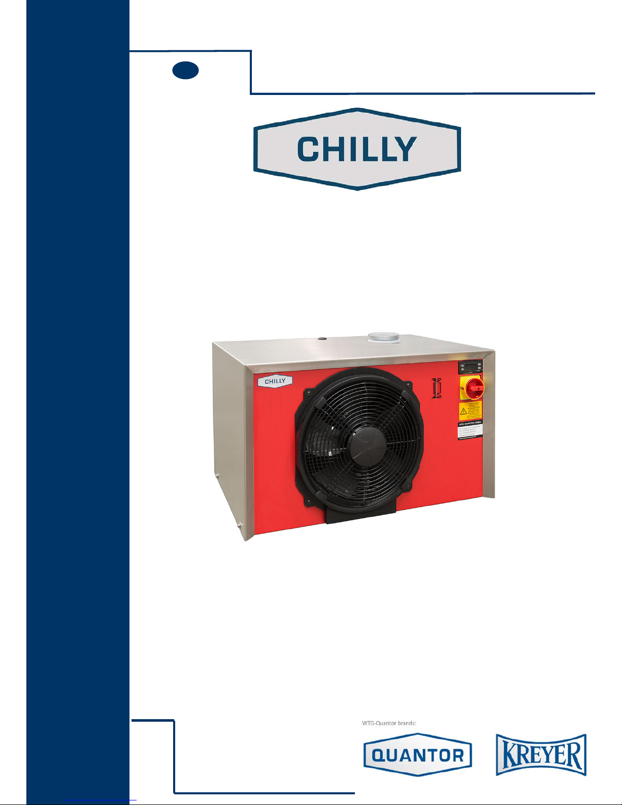
INSTRUCTION MANUAL CHILLY
COMPACT
WATER-CHILLER
INSTRUCTION MANUAL
WTG – QUANTOR GmbH
Europa-Allee 53
D-54343 Föhren
Tel: +49 (0)6502 99 995-0
Fax: +49 (0)6502 99 995-75
www.quantor.technology • [email protected]nology
Nr.
ENG
Page 2
Operating Instructions 1
OPERATING INSTRUCTIONS
1 SAFETY / PREVENTION OF ACCIDENTS 2
2 TRANSPORT 4
3 INSTALLATION AND INITIAL OPERATION 5
4 CARE AND MAINTENANCE 9
5 FAULT DIAGNOSIS 11
6 IMPORTANT INFORMATION
ON WATER QUALITY 14
7 PLATE HEAT EXCHANGER (OPTION) 16
8 WASTE DISPOSAL 16
APPENDIX
- TECHNICAL DATA
- TEMPERATURE CONTROLLER
- WIRING DIAGRAM
These operating instructions have to be read carefully before putting the
chiller into operation.
Please observe these instructions, otherwise the manufacturers liability for subsequent damage will be cancelled.
All rights required for further technical development and modifi cation, are reserved.
Proper use of the chiller
This chiller is designed for the cooling of water only. For the use of other agents (e.g. deionised water) please contact
the manufacturer. Limits indicated in the technical data must be adhered to strictly, otherwise the manufacturers
liability for subsequent damage will be cancelled. Chilling of fl ammable or explosive substances is prohibited.
Please keep these operating instructions
for further use!
IMPORTANT!
IMPORTANT!
Page 3

2 Operating Instructions
General information
These operating instructions contain valuable information which has to be observed during initial
start-up, operation and maintenance. Therefore these instructions are to be read by the installer and operating personnel in charge, before putting the chiller into operation.
All general safety instructions mentioned in this chapter and special security instructions given in other sections of
this manual have to be observed.
Personnel qualifi cation and training
Operating, maintenance, inspection and installation personnel must be qualifi ed. Responsibility and supervision
must be clearly explained to the operator.
Danger due to non-observance of safety instructions
Non-observance of safety instructions may cause injuries, endanger the environment or damage the chiller. Nonobservance of safety instructions will cancel the manufacturers liability for subsequent damage.
Safety conscious operation
The safety instructions given in these operating instructions, including national regulations on accident prevention
as well as any specifi c chiller safety instructions must be observed.
Safety instructions for user / operator
Protective guards that have been installed to prevent contact with moving parts may not be removed when the unit
is being operated. Danger resulting from the use of electrical power is excluded (for detailed information, refer to
the VDE regulations and the regulations of the local power supply authorities).
Safety instructions on maintenance, inspection, and installation work
Basically none of the cleaning or maintenance tasks may be performed until the unit has come to a complete standstill. As soon as this work has been completed, all the safety devices and protective equipment must be mounted or
installed according to their proper function.
Arbitrary modifi cation and production of spare parts
The unit may be converted only if an agreement has been reached with the manufacturer. Original spare parts and
accessories accepted by the manufacturer serve as safety guarantee. Use of other parts may cancel the manufacturer‘s
liability for subsequent damages
1 SAFETY / PREVENTION OF ACCIDENTS
Page 4
Operating Instructions 3
Non-permissible operating methods
The operational safety of the delivered unit is guaranteed only if the unit is properly used as intended.
Limits indicated in the technical data must not be exceed
Health hazards with the refrigerant
The refrigerant has only a very low acute health hazard. It has narcotic effects only at extremely high concentrations. After acute exposure to extremely high concentrations the substance is eliminated over the lungs very quikkly. The refrigerant has a certain irritating effect on skin and mucous membranes. Exposure of the skin to liquid
refrigerant can cause frost bite. In the presence of open fl ames or hot surfaces refrigerant can decompose and form
toxic decomposition products (e.g. hydrogyn chloride, phosgene). The refrigerant evaporates when exposed to air
. Intentional exposure of refrigerant is not permissible. The chiller must be handled with great care to prevent any
damage occuring through transport operations.
1 SAFETY / PREVENTION OF ACCIDENTS
Safety symbols
This symbol is to be found next to all the safety instructions involving work that
may result in serious injuries. Observe these instructions and proceed with extreme
caution in such instances. Inform all other users as well. In addition to the instructions included in this manual, the applicable general safety and accident prevention
regulations must also be taken into account.
This symbol is to be found next to the items in this manual that must
be strictly observed to ensure proper application of the guidelines, regulations, instructions and procedure of tasks and to make sure that the machine or other parts are not
damaged or destroyed.
This symbol explains that chiller is designed according to state-of-the-art technology and
is safe to operate. Dangerous situations may, however, be the result if the unit is used
by personnel without adequate qualifi cation or if it is not used correctly according to its
intended purpose. Accordingly, this may affect effi cient operation of the unit.
Warning!
Attention!
Note!
Page 5

4 Operating Instructions
The chiller may only be transported in original packaging to the site of initial operation. In case of damage the manufacturer must be informed immediately. If the unit is moved to another location in a factory, all connections must
be disconnected from the unit. Moving the unit to another location must be carried out without causing damages.
If damage occurs despite these instructions, the unit must be checked by an expert and repaired as required before
it is put into operation again.
Note:
The Manufacturers Liability excludes any Damage to the Chiller
subsequent to Transportation.
When transporting the unit, consider the weight limits indicated in the technical data.
Use a fork-lift, truck or a crane with the corresponding load-capacity.
The fully-hermetic compressor is mounted on rubber. Avoid vibrations during transport.
Failure to observe can result in compressor damage.
2 TRANSPORT
Page 6
Operating Instructions 5
Installation
Prior to installation and commissioning of the chiller, please observe the following points strictly:
The fresh air intake temperature may not exceed the max.ambient temperature
(refer to name plate)
Assure that the required quantity of air is available at air cooled chillers.
Assure that the chiller hot air outlet does not warm up the environment or room excessivly.
Min.distance of fresh air intake: at least 0,5 m (air cooled version)
Min.distance of hot air outlet: at least 1,0 m (air cooled version)
Connection of an air supply and exhaust duct is not admitted.
The fresh air intake of the unit (condensor) may not be situated infront of a heat rejecting
device like a pump or electric motor.
The unit must be set up on level, solid surfaces only, in order to ensure the required stability.
For outside erected chillers, the minimum outdoor temperature should be considered from the
technical data.
Floor space
A minimum space must be left open around the installation, so that there is access to the various components and
to the control cabinet.
The distance from any constructions blocking the air supply must be at a minimum
distance of 0,5 meter.
3 INSTALLATION AND INITIAL OPERATION
According to EN 60204-1 the chiller must be positioned in a way that its power switch is located
at a height between 0.6m-1.9m above the access level (floor).
Page 7
6 Operating Instructions
Electrical connection
The chiller is ready for connection and is connected to a one or three phase current network
(mains voltage refer to technical data).
The power supply has to be connected in a right handed rotatory fi eld. In order to confi rm the
correct connection the direction of rotation of the fan motor must turn in the same direction as the
arrow.
All electrical connections in the switch board are to be tightened prior to commissioning.
Incorrect connection of power supply and incorrect power supply will cancel the
manufacturers liability for subsequent damage.
Hydraulic connection
After completing the electrical connection it is necessary to connect the Chiller to the consumer VIA fl exible or
fi xed pipes.
Selection of materials of pipes. PVC, Plastic, Stainless Steel, Copper and Brass are permissible.
Note: Mild Steel and Galvanized Steel is not permissible.
Selection of cross – section of pipes (for advise please refer to manufacturer).
Insulated pipes are to be used if the distance between the chiller and the consumer is greater
than 5 m.
Refer to technical data (pump diagram) for fl ow rate and pressure available from the chiller.
Before starting up it is always necessary to prime the pump with the medium to be transported.
(refer to BLEEDING OF PUMP in this chapter).
If the consumer is placed on a higher level than the chiller unit, a non-return valve has to be
recommend in the water outlet as well as an solenoid valve has to be installed in the water inlet.
Connect water inlet port to consumer return line.
Connect water outlet port to consumer inlet line.
Connect water supply port (if available) to city water net.
Please test fl oat valve adjustment (option). Float valve is factory adjusted at 3 bar water pressure.
Incorrect hydraulic installation will cancel the manufacturers liability for subsequent damag
Refi lling of the tank
Automatic refi ll
Tap/fresh water feed connected to water supply port guarantees constant level in the tank, so that evaporator always
remains submerged.
Manual refi ll
Filling of water manually through water inlet port or directly into tank.
The waterlevel can be observed by the water sightglass which can be seen from the outside of the
housing. Ensure that the evaporator is submerged.
3 INSTALLATION AND INITIAL OPERATION
Page 8
Operating Instructions 7
3 INSTALLATION AND INITIAL OPERATION
Important:
Prior to fi lling of the tank it is esessential to test the water quality and if required carry out watertreatment (refer to chapter 7).
To avoid corrosion at the stainless steel evaporator, we recommend to use water with a low salt content (chloride
content < 20 mg/l). To avoid thickening of the tank water, we recommend to replace the system content every 1 to
3 months.
an increasing evaporation of the tank water means an increasing chloride content
(please refer to chapter 6).
For chillers running at temperatures lower than freezing point, a water/glycol mixture at the
appropriate ratio should be fi lled.
30% Glycol up to –10°C, at lower temperatures please refer to the manufacturer.
The tank should be fi lled to the max. level of the water level tube.
Prior to start up it is always necessary to prime the pump with the medium to be transported.
Prior to start up the pump must be bled in order to remove air from the pump.
Bleeding of the pump
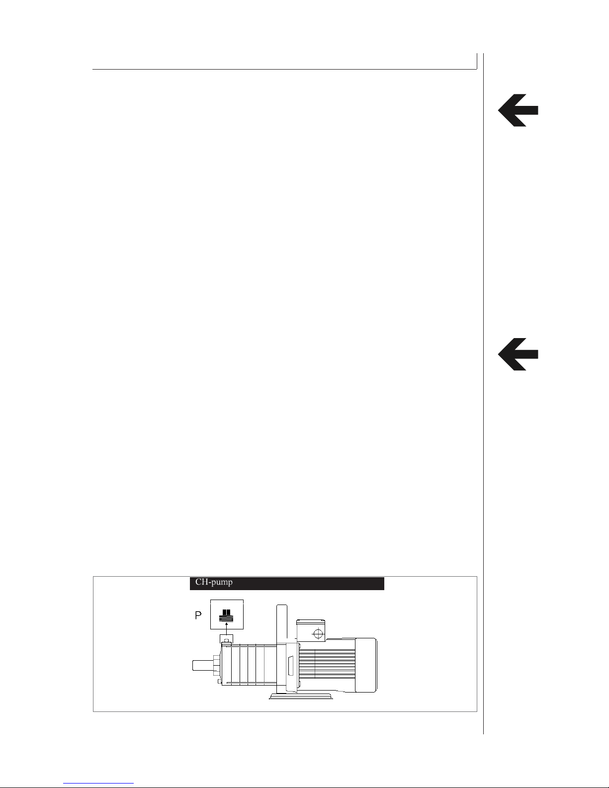
Remove bleeding screw P (option)
Reinstall bleeding screw and tighten as soon as medium exits from fi ller fi tting.
Important: Ventilation of the pump
before start the process,following steps are to relize for ventilate the pump:
check the waterlevel in the tank and refi ll it, if necessary
open the outlet of the pump, or
connect only the outlet of the pump, let the inlet free fl ow out
If there is still some air in the system, you have to repeat the steps as described before.
After open the outlet start the pump for a short time.
Attention
before start the operation of the pump, the function of this pump must be absolutly check.
In case that the pump after a longer standstill and ventilation stopp , you have to introduce a
screwdriver through the airgrille into the shaft and turn it clockwise (1-2 turns min. ), until a easiness is produced.
Page 9

8 Operating Instructions
3 INSTALLATION AND INITIAL OPERATION
Start–up of chiller
After successful completion of all instructions given in this chapter, the refrigerating plant is switched
on by means of the main switch or master switch (if installed). The OPERATION light will light up
during normal operation.
Master switch position: O = Off 1 = Operation
In case of irregularities occurring during operation or extraordinary noise, the chiller has to be
switched off by means of the control switch (please contact the manufacturer).
Confi rm the correct power supply connection.The direction of rotation of the fan motor must turn in
the same direction as the arrow.
Page 10
Operating Instructions 9
4 CARE AND MAINTENANCE
General
In case of irregularities occurring during operation or extraordinary noise, the chiller has to be switched off by means
of the main switch or if missing over the power supply.
Fluid (water)
Cleanliness of the water/fl uid should be tested daily. If required, the water/fl uid has to be drained and the evaporator,
tank and pump has to be rinsed or cleaned.
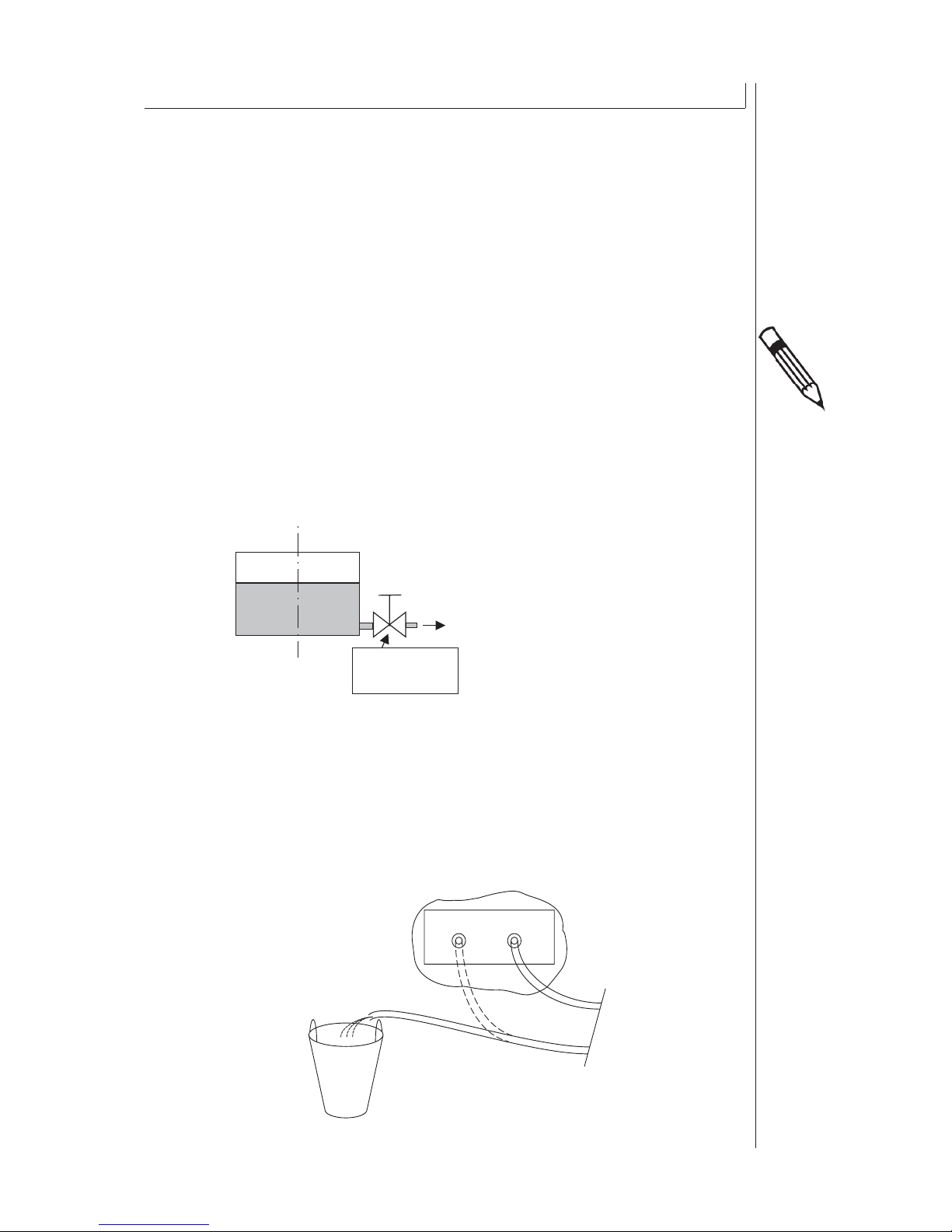
Drain water from the tank as follows:
Option - drain water through water drain valve (A) Special equipment available on request
By disconnecting the connection medium on the water inlet side while the pump is running
Attenion: use a buchet (B).
Water drain
valve
(B)
(C)
chiller
consumer
Page 11

10 Operating Instructions
Refi lling of fl uid
Automatic refi ll (option)
Automatic water feed guarantees constant level in the tank, ensure that the evaporator always remains submerged.
Float valve function has to be tested regularly.
Manual refi ll
Ensure that the evaporator is always submerged.
Water supply
Larger volumes of fresh water supply may disturb the equilibrium of mixture or reduce concentration of antifreezing
agent. The content of concentration should be checked and determined at required intervals of time.
Standstill for prolonged period
Longer standstill of chiller requires draining of tank and complete water circuit. For renewed start-up of the chiller
the same steps as for the initial start-up must be considered.
Cleaning of condenser (air-cooled chillers)
Make sure that the cooling fi ns of the condenser remain clean in order to guarantee the required heat exchange.
The condensor must be cleaned in monthly intervals or if required at shorter time intervals.
Dust and dirt clogging up the cooling fi ns should be removed by means of compressed air.
4 CARE AND MAINTENANCE
Page 12
Operating Instructions 11
By means of the following instructions a quick failure analysis can be made. The user can repair some failures
without any assistance. Please do not hesitate in phoning the manufacturers after sale service department if assistance is required.
Corrective maintenance of the refrigeration cycle must be performed by competent refrigeration specialists
only. In case of any problems concerning the refrigeration cycle, please contact the manufacturer
5 FAULT DIAGNOSIS
Note:
Please ensure to switch »0« the main switch, before any maintenance or
repairment work has to be performed on the chiller.
Page 13
12 Operating Instructions
5 FAULT DIAGNOSIS
Fault
Refrigeration cycle
Possible cause Repairement
A. Compressor and fan motor
running, but chiller has no
cooling capacity
Refrigerant leakage refrigerant level to low
Repairement by qualifi ed
refrigeration technician only
Dirty condensor Clean condensor
Ambient temp. to high Refer to technical specifi cations
Consumer capacity to high Refer to technical specifi cations
B. Compressor and fan motor is
not running
Temperature controller setting incorrect
Re-adjustment of temp. controller
Temperatur controller defect Replacement by qualifi ed techni-
cian only
Fan Motor defect Switch off the chiller and restart
after 3 hours only.
If compressor does not start,
replacement by qualifi ed
refrigeration technician only.
If compressor starts, refer to D.
C. Compressor does not run, but
fan motor is running
Compressor Bimetal/Clixon
switches compressor of due to
overheating
Switch off the chiller and restart
chiller after 3 hours only.
If compressor does not start,
replacement by qualifi ed refrigeration technician only.
If compressor starts after 3 hours 1. Refrigerant leakage -
refrigerant level to low
2. Dirty condensor
3. Ambient temp. to high
4. Consumer capacity to high
D. Compressor is running, but
fan motor does not run
Fan Motor defect Replacement by qualifi ed techni-
cian only.
Page 14

Operating Instructions 13
5 FAULT DIAGNOSIS
Fault
Water cycle
Possible cause Repairement
Pump is not pumping any water Air in the water cycle Refer to air bleeding instructions
in Documentation
Pump fuse defect Replace fuse
Pump defect Replacement by qualifi ed techni-
cian only
Page 15

14 Operating Instructions
6 IMPORTANT INFORMATION ON WATER QUALITY
In order to achieve a correct and trouble-free operation on your water chiller it is necessary to
examine the water quality and, when necessary, carry out water treatment. Corrosion, furring and biological
problems can occur in the water system.
The following information is important for the assessment of a half-open system:
- water quality
- all materials having contact with the cooling water
- max. and min. system water temperature
- requirements for water quality
1. Deionized / Demineralized / Destilled / Return Osmosis water
When using deionized, demineralized, destilled or return osmosis water it is required to add a
corrosion inhibitor or glycol to the water system.
2. Fresh water/ City water / Tap water
When using fresh water, city water or tap water it is recommended to analyse the water by a
specialist to minimize the risk of any chiller damage through a high chloride content. A high chloride content
(>20mg/l) in the system water can cause corrosion on the stainless steel evaporator.
It is required to make use of a corrosion inhibitor as additive to the system water. We recommend the use of
Nalco 77382 at a concentration of 5g/l in the complete water system, unless an Inhibitor with similar characteristics is prescribed from the manufacturer.
Organic sediments and algae in the water cycle can be controlled by analysing the number of organic germs. If
the number of organic germs exceeds 1000 KBE/ml, we recommend to use
Biozid Nalco 77352 at a concentration of 100mg/l. After 3 to 4 days it is recommended to exchange the
complete system water. The chiller can operate during this period.
Evaporation leads to a concentration of minerals and chloride in the system water, especially at the surface level.
The water parameters which are initially below the guide values, can increase to exceed the guideline value as a
result of the evaporation. An excessive chloride content in the system water will cause corrosion on the stainless
steel evaporators and stainless steel tank. We therefore recommend to regularly monitor the water quality and if
necessary drain the concentrated water from the system in order to rematch the water values to the parameters as
per guideline. It is recommended to exchange the water at least once or more times per year and to inspect the
evaporators on regular intervals.
Water quality parameters:
ph-value: 7-9 alkality (°dH): <1
conductivity: <300 µS/cm chloride content: <20 mg/L
hardness (°dH):
7,5-8,5
organic germs: <1000 KBE/ml
For any further questions please contact the water specialist (S. 16)
Ignorance of the above information cancels the Manufacturers liability for
subsequent damage.
Page 16

Operating Instructions 15
6 IMPORTANT INFORMATION ON WATER QUALITY
For assistance regarding watertreatment please contact:
GERMANY
Nalco Deutschland GmbH
Ludwig-Landmann-Strasse 405
D-60486 Frankfurt am Main
Phone: 069-793-40
Fax: 069-793-4295
FRANCE
Nalco
N°5 rue Rosa Bonheur
F-59290 Wasquehal
Phone: 03 20 11 70 00
Fax: 03 20 11 70 70
EUROPE
Nalco European Operations
2342 BV Oegstgeest
P.O. Box 627, NL-2300 Leiden, The Netherlands
Phone: 31-71-524-1100
Fax: 31-71-524-1197
USA
Nalco Company
Nalco Center
1601 W. Diehl Road
Naperville, IL 60563-1198 U.S.A.
Phone: 630-305-1000
Fax: 630-305-2900
SOUTH AMERICA
Nalco Latin America Operations
Av. Das Nacoes Unidas
17.891, 11o, Andar
Santo Amaro 04795-100
Sao Paulo, Brazil
Phone: 55-11-5644-6500
Fax: 55-11-5641-7687
ASIA
2 International Business
# 2-20 The Stategy Tower 2
Singapore 609930
Phone: 0065 (0) 68 61 40 11
Fax: 0065 (0) 68 61 40 11
Page 17
16 Operating Instructions
7 PLATE HEAT EXCHANGER (OPTION)
Cleaning of plate exchanger
Soldered heat exchanger: For the removal of lime- and rust deposits, purifying agent SWEPcip AS, RS, CS or
S (according to material) is suitable. Cleaning may be performed by means of SWEP cleaning device C.I.P 90
(circulation method) or a stationary pump.
Screwed heat-exchanger: In this case the heat exchanger can also be disassembled for cleaning.
See attached concept for further technical data
Stainless steel
Lime Rust Lime + Rust
SWEPcip AS SWEPcip CS SWEPcip AS
Max. Temp: 80 °C 80 °C 80 °C
Max. time: 8 h 8 h 8 h
Mixture ratio: 1:10 1:5 1:10
Steel Lime Rust Lime + Rust
SWEPcip AS SWEPcip RS SWEPcip S
Max. Temp: 80 °C 80 °C 50 °C
Max. time: 8 h 8 h 8 h
Mixture ratio: 1:10 1:5 1:5
8 Waste disposal
The refrigerant cycle of the chiller contains an enviroment friendly refrigeration fl uid. Only registered and qualifi ed refrigeration companies are permissible to carry out work on the chiller. Before attending any repairments or
maintanance work on the refrigeration cycle the refrigerant must be recovered by means of a recovery unit. Any
intention blowing off the refrigerant is prohibited. Disposal of the refrigerant and any other parts like compressor
oil or waste water must be completed according to local regulations only.
Specifi cation subject to change.
Page 18

Operating Instructions 17
FOR YOUR NOTICE
Page 19
Hersteller:
Manufacturer:
Fabricant:
Produktbezeichnung:
Product description:
Descriptions produits
Seriennummer:
Serial number:
Numéro de série:
Konformitätserklärung
Declaration of Conformity
Declaration de Conformite
WTG-QUANTOR GmbH
Europa-Allee 53
D-54343 Föhren
-
Kühlanlage zur Rückkühlung von Flüssigkeiten
-
Chiller
-
Refroidisseur
Hiermit erklären wi r , dass nachfolgend genannte Produ kte aufgrund ih rer Konzep tion, Konstruk tion und Baua rt in der vo n uns in
Verkehr g ebrachten Ausführung den grundlegenden Sicherheitsanforderungen der nachstehend genannten Ri chtlinien
einschließlich der zum Zeitpunkt der Erklärung geltenden Änderungen entsprechen.
Einschlägige EG-Richtlinien: - EG-Maschinenrichtlinie 2006/42/EG
-
EG-EMV Richtlinie 2014/30/EU
Angewandte harmonisierte Normen: - DIN EN ISO 12100:2011-03; Sicherheit von Maschinen, Allgemeine Anforderungen
-
DIN EN 60204-1:2007-06; Sicherheit von Maschinen, elektrische Ausrüstung von
Maschinen
-
DIN EN 378-1 bis -4:2012-08, Kälteanlagen und Wärmepumpen -
Sicherheitstechnische und umweltrelevante Anforderungen
We herewith confirm that the following products based upon their construction as well as their distributed version meets the
relevant basic security and health requirements of the EC directives below referenced, including any alterations made at the time
of the declaration.
Applied machine Directives: - EC- Machine Directive 2006/42/EG
-
EC- EMV Directive 2014/30/EU
Applied harmonized Standard: - DIN EN ISO 12100:2011-03: Safety of machines, General requirements.
-
DIN EN 60204-1:2007-06;Safety of machines, Electrical Equipment of machines
-
DIN EN 378-1 to -4:2012-08, Refrigeration and Heat pump systems –
safety and environmental requirements. Requirements
Par la présente nous déclarons que les produits suivants de part leur fabrication et de part leur distribution sont conformes aux
exigences essentielles de sécurité et de santé des directives CE ci-dessous référencés, incluant leurs avenants publiés à ce jour.
Directives CE Appliquées: - EC- Directive Machine 2006/42/EG
-
EC- Directive CEM 2014/30/EU
Standards Harmonisés Appliqués: - DIN EN ISO 12100:2011-03; Sécurité des machines, exigences générales.
-
DIN EN 60204-1:2007-06; Sécurité machines, équipements électriques des machines
-
DIN EN 378-1 à -4:2012-08, Systèmes de Réfrigération et Pompes à Chaleur –
Sécurité et exigences environnementales
Föhren, 01.02.2016
Markus Milz
Managing Director
(Bevollmächtigte Person zur Zusammenstellung de r technischen Unterlagen und zur Ausstellung dieser Erklärung)
(Authorized person for technical docume ntation and for issuing this clarifi cation)
(Personne autorisée pour la documentation technique et pour publier le présent declaration)
DOK-ID: V1.03_KAT 1
Page 20

T E C H N I C A L D A T A S H E E T
Kühlwasser-Rückkühler
Typ Chilly 45-M/USA-230/1/60-M
1. GENERAL DATA
Refrigerant gas: R404A
Specifications:
Nominal ambient air: °C 32
Coolant temperature: °C -8 0 15
Cooling Capacity: W 450 1500 4000
Min ambient air: °C 10
Max ambient air: °C 42
Min coolant temperature: °C -10
Max coolant temperature: °C 25
Evaporator material: Copper
Temperature control: electronic, direct
Temperature display: digital
(118771)
Control voltage: 230V AC
Main Power supply: 1/N/PE/60Hz 230V/+-10%
Total absorbed power: kW max: 2.8
Full load current: A max: 14.1
Safety fuse protection: A 16.00
Sound-pressure-levels in 1m Distance: dB(A) 70.00
Paint: Abdeckhaube Edelstahl;Bodenblech RAL3000
2. AIR CONDENSER: air cooled, axial
Nominal Air Flow: m³/h 2390.00
Number of fan: Unit 1
Nom Absorbed power: kW 0.18
Starting current: A 0.81
3. COMPRESSOR: reciprocating
Number: Unit 1
Technology: direct
Total absorbed power: kW max: 1.80
Full load current: A max: 9.43
4. PUMP:
First PUMP: horizontal centrifugal pump
Type: CM1-3
Number: Unit 1
Page 1 / 2
Page 21

T E C H N I C A L D A T A S H E E T (118771)
Total absorbed power: kW 0.60
Full load current: A 3.60
Nominal flow rate: m³/h 0.80
Nominal pressure rate: bar 3.50
5. LIQUID TANK: plastic
Volume: l 26.00
Outlet / inlet connections: Inch 1/2
6. WEIGHT AND PHYSICAL SIZE:
Length: mm 760
Width: mm 610
Height: mm 500
Weight : kg 81
Page 22
23.08.2012 ST120
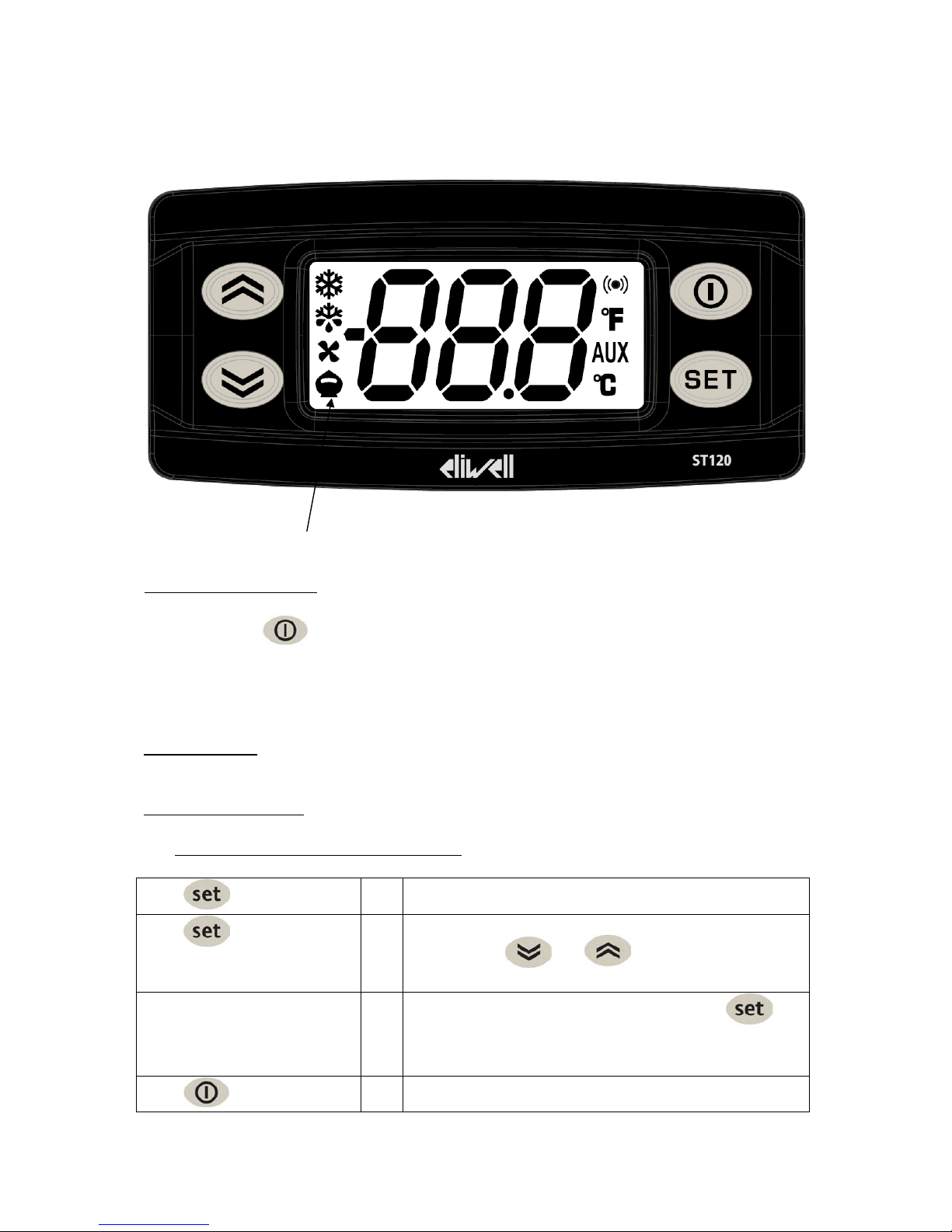
Description of the controller Eliwell ,ST120,
1.
Switch On/Off: (Option)
Push the button long (>5 seconds) to switch from operation mode „Off“ to „On“ and
converse.
In the mode „Off“ the display will show Off.
2. Normal display:
The actual medium temperature is displayed.
3. Adjusting the setpoint:
a. Fixed value regulation (absolute control)
push
1x short
⇒
SEt
is displayed
push 1x short
⇒
the setpoint appears in the display, you can adjust it
by pressing or
It will be saved in the controller by pressing
The display will switch back to Set.
push 1x short
⇒
The actual mediumtemperature is displayed
operation indicator
Page 23
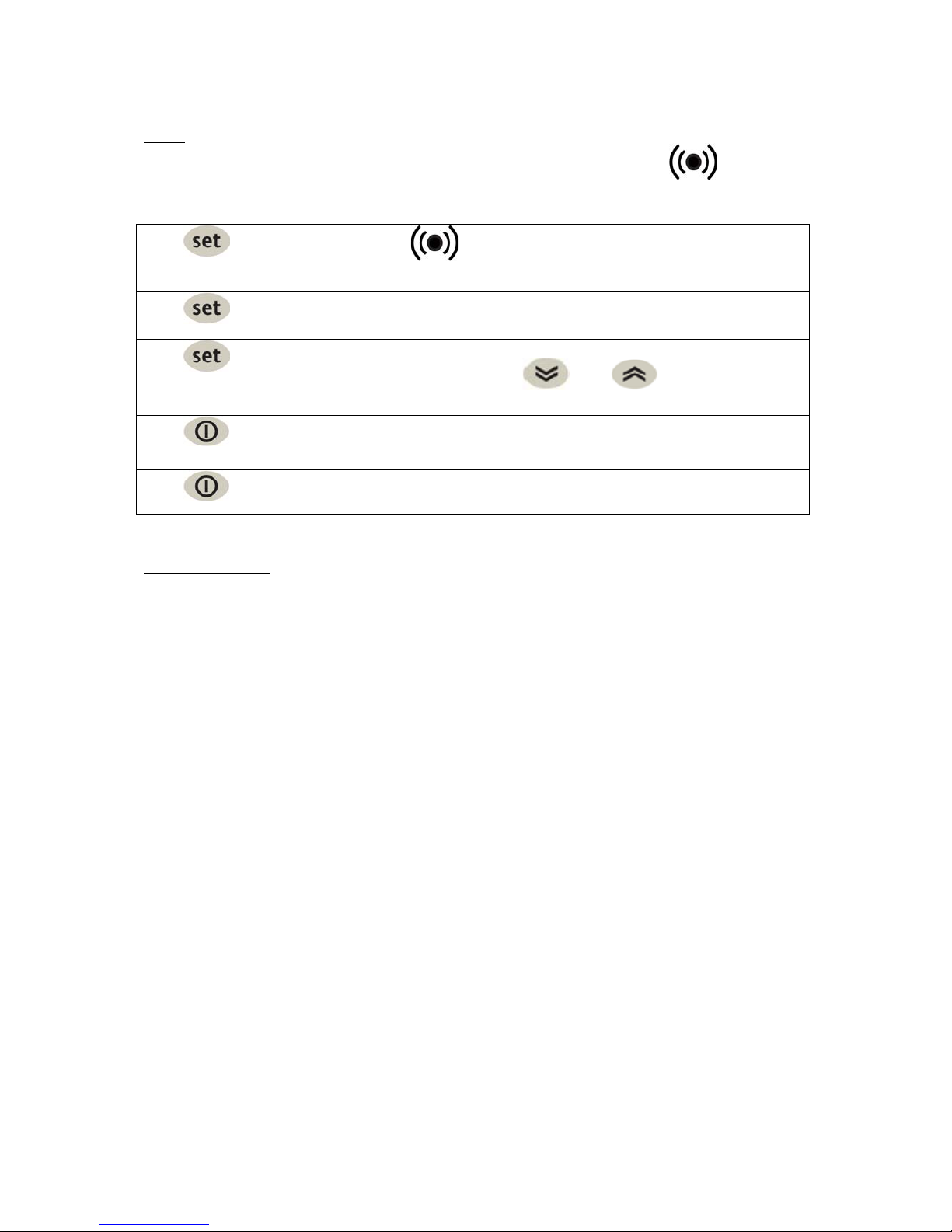
23.08.2012 ST120
4. Fault:
As soon as one or more faults appear this will be displayed by this symbol
To get the list of the existing faults displayed proceed as follows:
push 1x short
⇒
is displayed
push 1x short
⇒
AL
is displayed
push 1x short
⇒
List of fitting mistakes, those can be shown with the
following button:
and
push 1x short
⇒
AL
is displayed
push 1x short
⇒
The controler will be shown as standard indication.
5. Alarm indications
Number Desciption
E1
Sensor1fault
E2
Sensor2fault
E3
Sensor3fault
AH1
Alarmhightemperature
AL1
Alarmlowttemperature
Opd
Digitalinputdisconnected
Page 24
Zust. Änderung
Elektrodokumentation
Electrical documentation
Anschlußdaten
Technical data
Anschlußspannung
Voltage
Frequenz
frequency
Steuerspannung 1
control voltage 1
Steuerspannung 2
control voltage 2
Anschlußleistung
Total absorb power
Max. Betriebsstrom
Full load Current
Max. Vorsicherung
Safety Fuse
Datum Name
Datum
Bearb.
Gepr.
Norm
28.04.2015
Bruchhof
Wiebe
:
:
:
:
:
:
:
Ursp.
230 V
60 Hz
230 V
---
2,9 kW
14,4 A
16 A
Ers. f. Ers. d.
Maschinentyp
Type
Anschlußdaten
Technical data
:
Chilly 45-M/USA-230/1/60
Zeichng.
Nr.
Typ
E0012482
Chilly 45-M/USA-230/1/60
=
+
Blatt
von51Blatt
Page 25
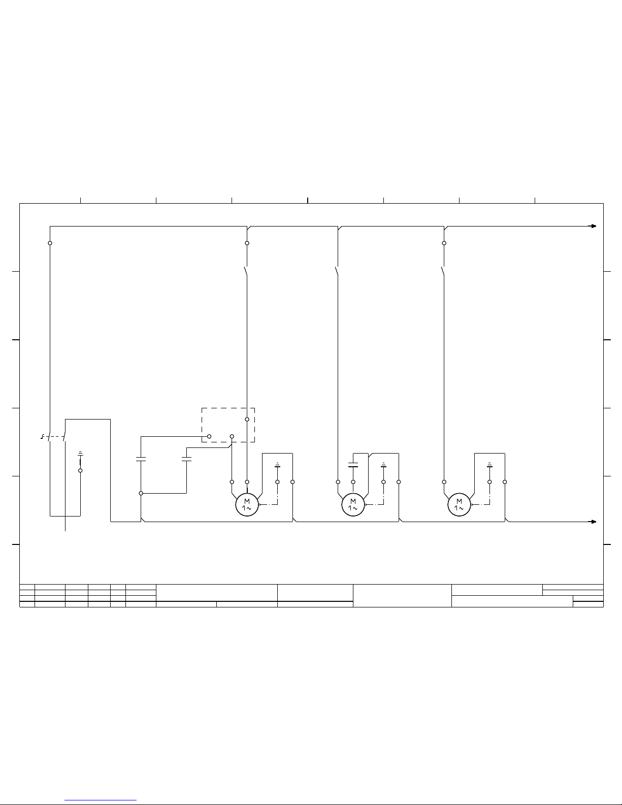
X1 L1
Q1
214
3
X1 PE
C1
X1 N
C2
K2
1 2
X1 1
1,80 kW 9,43 A
Kompressor
compressor
M1
a pc
X1 L1
Q2
3.2
1
2
5
2 X1 PE N
Q2
3.2
3
4
X1 3
0,25kW 1,10A
Lüfter
fan
M2
bl swbr
C3
4 X1 PE N
X1 L1
Q3
3.5
1
2
X1 5
0,6 kW 3,6 A
Pumpe
pump
M3
X1 PE N
L1
3.1
N
3.1
Betriebskondensator
run capacitor
Anlaufkondensator
start capacitor
Einspeisung
power supply
Sämtliche Leitungen ohne besondere Querschnitts-angabe sind H07V-K 2,5mm ²
all cables without numbers are H07V-K 2,5mm ²
K2
Anlaufrelais
start relais
A
B
2 3 4 5 6 7 81
2
E0012482
Chilly 45-M/USA-230/1/60
Hauptstromkreise
Main circuit
5
Zust. Änderung Datum Name
Datum
Bearb.
Gepr.
Norm
Ursp. Ers. f. Ers. d.
Zeichng.
Nr.
Typ
=
+
Blatt
Blattvon
A
B
C
D
A
B
C
D
E
F
2 3 4 5 6 7 8
E
1
Bruchhof
28.04.2015
Wiebe
Page 26
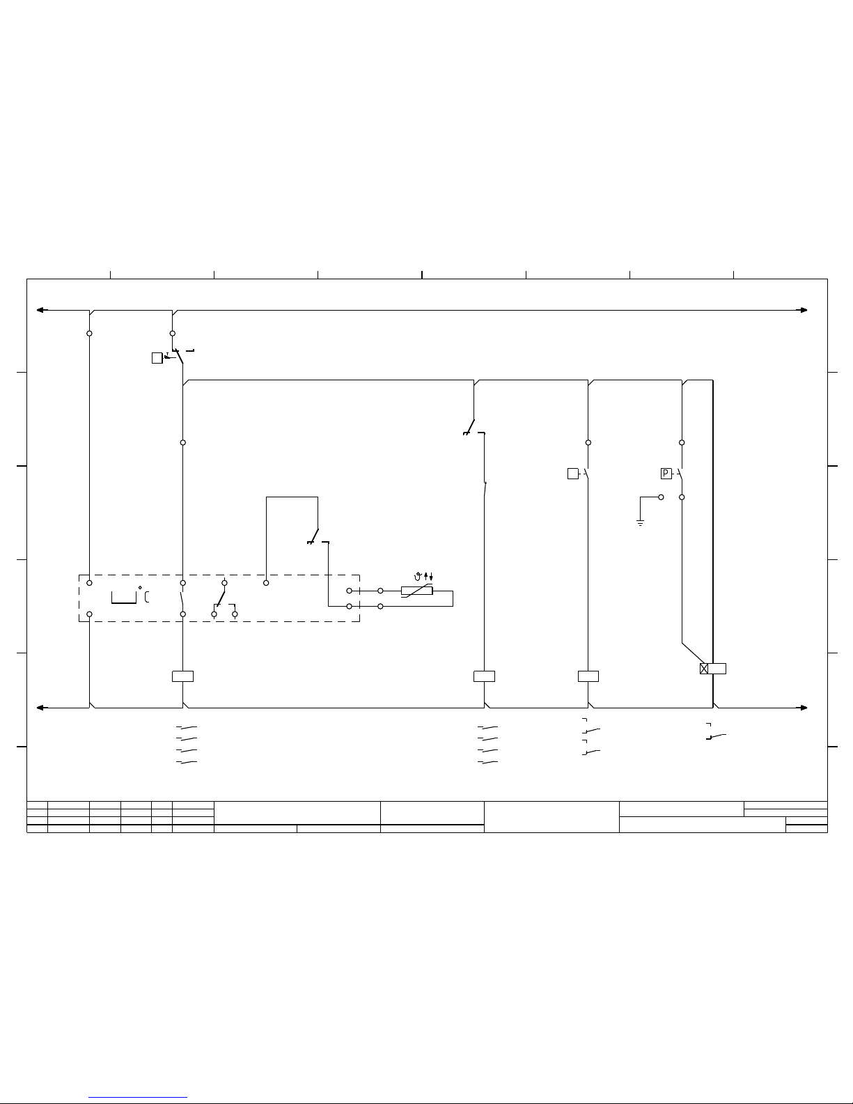
L1
2.8
N
2.8
X1 L1
3
4
15.0
K1
X1 L1
P>
>29,5 bar
F1
sw
rt
bl
X1 6
1
2
Q2
A1
A2
7
5
4.4
6
11
K4
3.6
121114
9
10
X1 7
X1 8
Mediumtemperatur
medium temperature
B1
K4
3.6
222124
K3
3.7
15
16
Q3
A1
A2
X1 9
H
max:250V 50VA
Trockenlaufschutz
additional level switch
for water destitution
B2
K4
A1
A2
X1 PE
X1 10
B3
11
K3
A1
A2
L1
4.1
N
4.1
Sämtliche Leitungen ohne besondere Querschnitts-angabe sind H07V-K 2,5mm ²
all cables without numbers are H07V-K 2,5mm ²
B1
Kennbuchstabe : B
rückfallverzögert mit Hilfsspannung
Einstellung : 30m/50 %
Druckschalter
pressure switch
Kompressor
compressor
Hochdruckschalter
high pressure switch
Pumpe
pump
Sammelstörung
collecting fault
A
B
2 3 4 5 6 7 81
3
E0012482
Chilly 45-M/USA-230/1/60
Hauptstromkreise
Main circuit
5
Zust. Änderung Datum Name
Datum
Bearb.
Gepr.
Norm
Ursp. Ers. f. Ers. d.
Zeichng.
Nr.
Typ
=
+
Blatt
Blattvon
A
B
C
D
A
B
C
D
E
F
2 3 4 5 6 7 8
E
1
Bruchhof
28.04.2015
Wiebe
1 2
2.4
3 4
2.5
5 6
13 14
1 2
2.6
3 4
4.2
5 6
13 14
3.3
14
12
3.3
11
3.5
24
22
3.5
21
3.5
18
16
3.5
15
Page 27
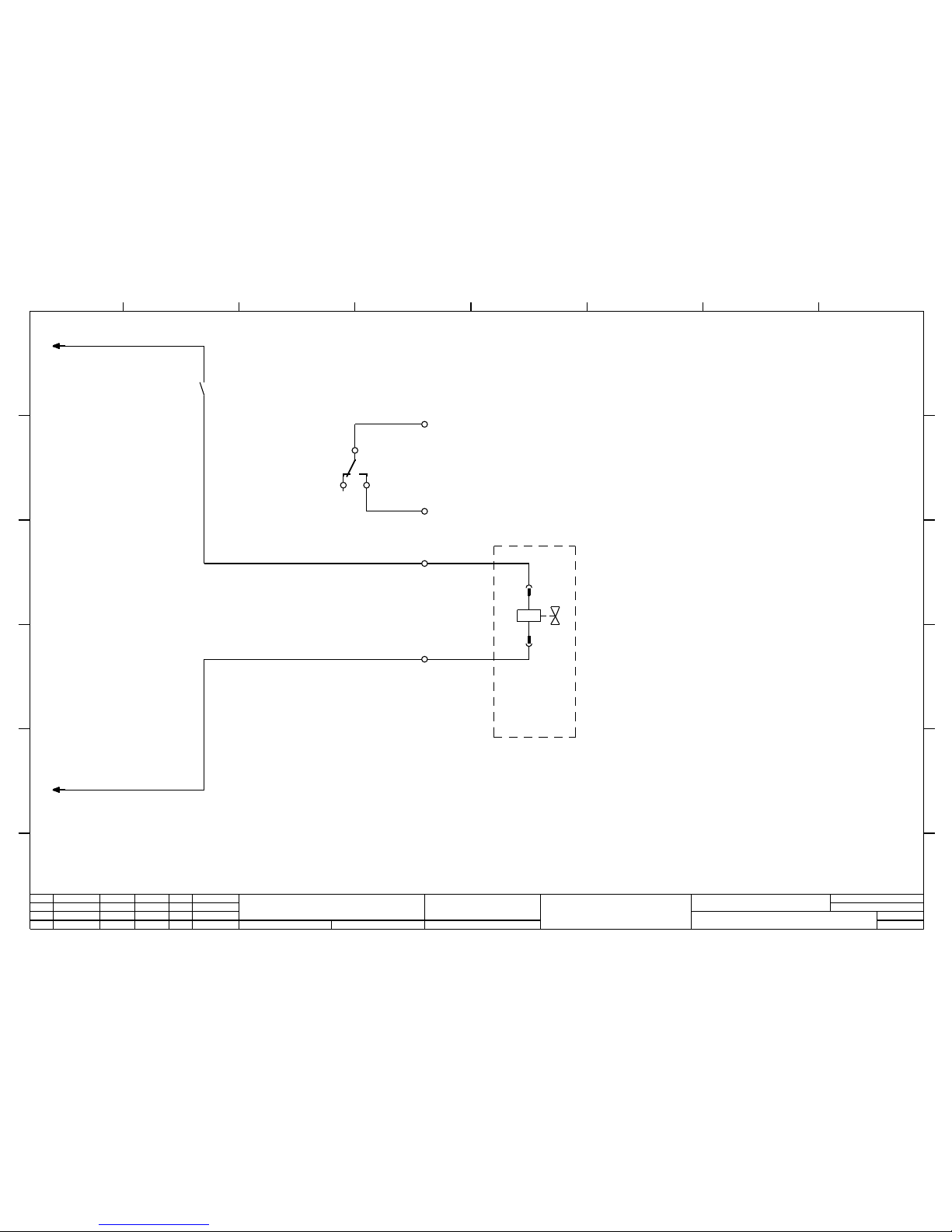
L1
3.8
N
3.8
Q3
3.5
3
4
7
5
3.3
6
X2 3
X2 4
X2 5
X2 6
1
Y1
2
Magnetventil
Solenoid Valve
Option
option
Sammelstörung
collecting fault
A
B
2 3 4 5 6 7 81
4
E0012482
Chilly 45-M/USA-230/1/60
Hauptstromkreise
Main circuit
5
Zust. Änderung Datum Name
Datum
Bearb.
Gepr.
Norm
Ursp. Ers. f. Ers. d.
Zeichng.
Nr.
Typ
=
+
Blatt
Blattvon
A
B
C
D
A
B
C
D
E
F
2 3 4 5 6 7 8
E
1
Bruchhof
28.04.2015
Wiebe
Page 28
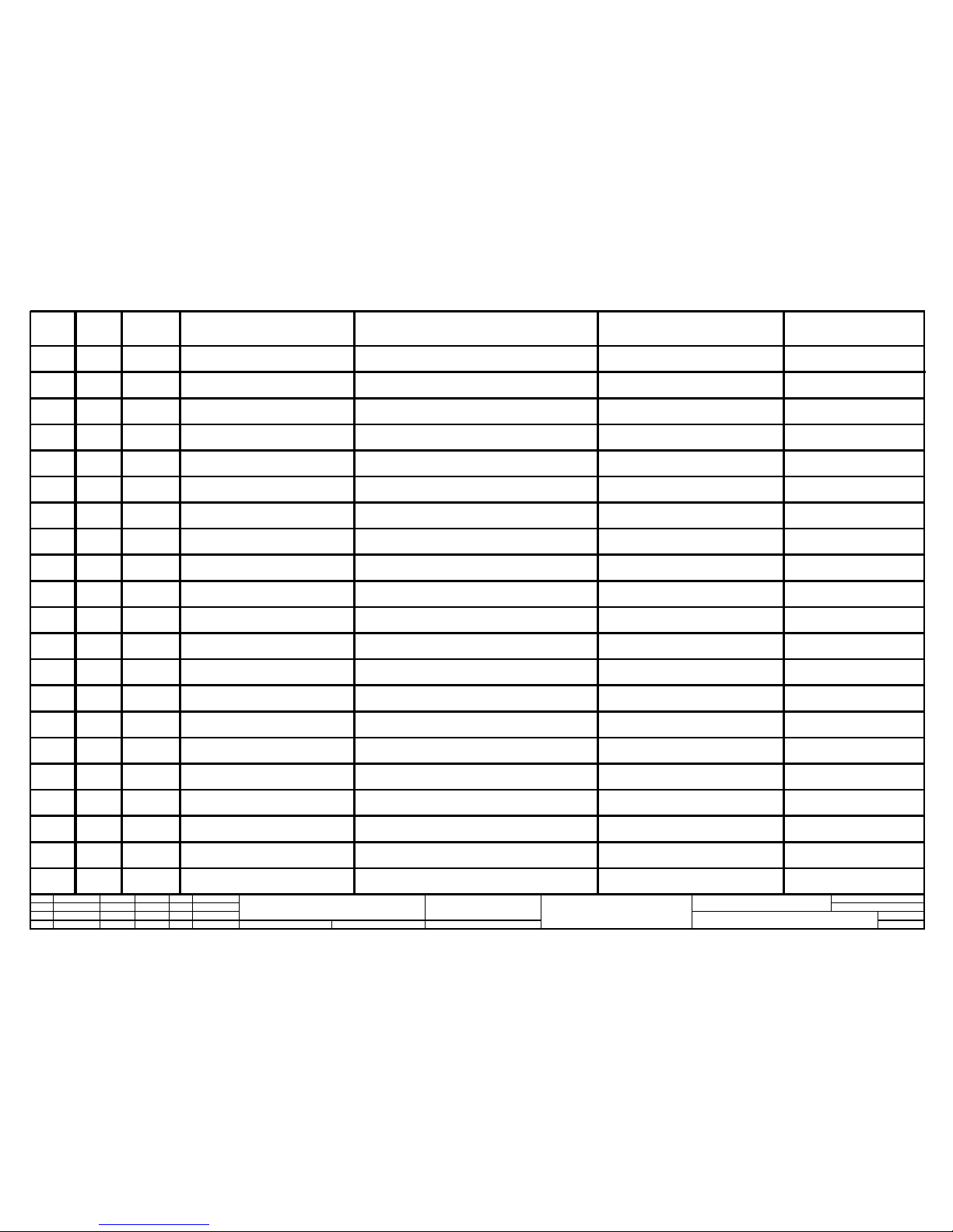
2
3
14
4
5
6
7
8
9
10
11
12
13
15
16
17
18
37206
11042
-- --
--- -
56135
-...-
28766
-------
22034
12484
28343
26383
64297.
69869
18315
17891
17891
32490 19
2
Schwimmerschalter
level switch
B3
Druckschalter
pressure switch
C1
Kondensator
Condenser
Kondensator
Condenser
Thermostat
thermostat
Kondensator
Condenser
Hochdruckbegrenzer
high pressure limiter
Schütz
contactor
Schütz
contactor
Zeitrelais
Time delay
Schütz
contactor
Kompressor
compressor
Lüfter
fan
Pumpe
pump
B2
C2
F1
K1
C3
K2
K4
K4
K3
M1
M3
Q1
M2
Q2
Q3
Y1
Hauptschalter
main-switch
Schütz
contactor
Schütz
contactor
Magnetventil
Solenoid Valve
NIG-A-G.3/8"Viton, PP
FF 115-S8 BAR, NEU PS1 A 8 R
100µF
17,5µF
5µF
ACB 061F9248
ST120 230V AC
Anlaufrelais
3RP1000-1AP30 , 3RP2005-1AP30
LZX:RT424730 230V AC
LZX:RT78625
CAJ 4517 Z
W4E350JN
CM 1-3 ,1x230 V, 60 Hz
H216-41300-2X062
3TG10 10-OAL2
3TG10 10-OAL2
21H12KOE120-UDA12230AS
1 56162B1
Fühler
sensor
NTC-Fühler, NTC 6x40mm 1,5m Kabel, IP 68
Elobau
ALCO
Tecumseh Europe- SA
Tecumseh Europe- SA
Eliwell
ebm-papst GmbH & Co.KG
Danfoss
Tecumseh Europe- SA
SIEMENS
SIEMENS
SIEMENS
L'Unité
ebm-papst GmbH & Co.KG
GRUNDFOS GmbH
Sälzer GmbH
SIEMENS
SIEMENS
SFS - Fluid Systeme GmbH
Eliwell
Bez.
Label
Seite
page
Pos.
pos.
Benennung
designation
Artikelnummer
Part number
Typ
type
Hersteller
manufacturer
2
2
3
3
2
3
3
3
2
2
2
2
3
3
4
3
3
3
5
E0012482
Chilly 45-M/USA-230/1/60
5
Zust. Änderung Datum Name
Datum
Bearb.
Gepr.
Norm
Ursp. Ers. f. Ers. d.
Zeichng.
Nr.
Typ
=
+
Blatt
Blattvon
Bruchhof
28.04.2015
Stückliste
Bill of Materials
Wiebe
Page 29
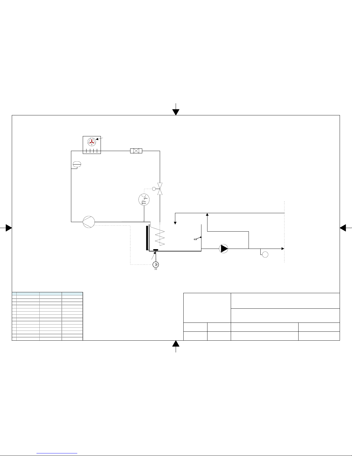
DATUM
bearbeitet
29.04.2015
geprüft
DATUM
ZEICHN. NR.
Blatt
DATUM
29.04.2015
Fließschema/ hydraulic schema/ schéma hydraulique
Type: Chilly 15-45-M
F4016
1von 1
D.BruchhofD.Krieger
3
2
1
6
13
14
11
1
5
stetiger Bypass, continual bypass
bypass permanent
8
34
PZAH
4
Nr. dt. engl. franz.
1 Kompressor compressor compresseur
2 Verflüssiger condenser condenseur
3 Lüfter fan ventilateur
4 HD- Pressostat hp- switch pressostat HP
6 Trockner drier déshydrateur
8 E xpansions ventil expans i on valve dét endeur
9 Verdampfer evaporator évaporateur
10 Thermostat thermostat thermostat
11 Fühler sensor sonde
13 Tank tank bac
14 F ül l s tandsanzeige fluid level indicator niveau visuel
15 Pumpe pump pompe
20 Druc k schalter hp- controller pressostat hp
34 S chwimmers c hal ter float switch controleur niveau
PSH
20
9
Page 30

Page 31

Page 32

INS TRUC TION MA NUAL C HIL LY
Dok-ID: V0.01-xx.02.2016
 Loading...