

Child Craft F10391 Instruction Manual
TM
SINCE 1954
Foundations® Worldwide, Inc.
5216 Portside Dr, Medina Oh 44256 USA • PH: 1 330.722.5033 • FAX: 1 330.722.5037
www.foundations.com
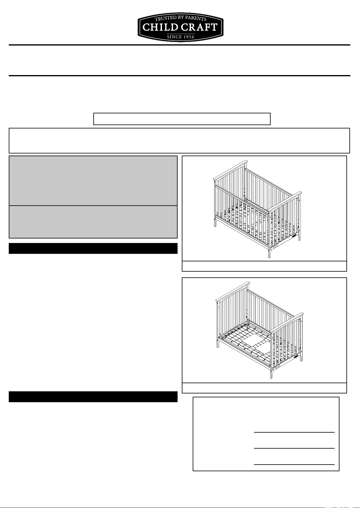
Monterey Full Size Traditional Wood Crib
Models Covered: F10391.
These Instructions Are For Cribs Manufactured After 11-2013.
KEEP INSTRUCTIONS FOR FUTURE USE
.
THIS IS THE ASSEMBLY INSTRUCTIONS FOR CRIBS SOLD IN CANADA
INSTRUCTIONS D’ASSEMBLAGE POUR LES LITS DE BÉBÉ VENDUS AU CANADA
FOR CUSTOMER SERVICE CALL
1-877-716-2757
(outside of U.S. 330-722-5033). DO NOT CALL
RETAILER OR RESELLER FOR SERVICE
AS THEY ARE NOT AUTHORIZED TO
RESOLVE ANY SERVICE ISSUES.
FOR FEDERAL SAFETY STANDARD
COMPLIANCE CERTIFICATES, PLEASE VISIT
OUR WEBSITE AT
www.foundations.com
ASSEMBLY ASSISTANCE
AB20047_G1
IMPORTANT: retain for future reference read
carefully.
Foundations® strives for the highest quality in our
products but occasionally a missing part or problem
can occur during assembly.
Assembled as Crib
If any parts are missing or broken or you need
assistance with assembly, DO NOT return the
product to your dealer. Go to our website at
www.foundations.com or Call Foundations®
for assistance at 1-877-716-2757 (U.S. Only) or
1-330-722-5033 (Monday through Friday, 9:00
a.m.– 4:00 p.m. Eastern Time). Please have the
model number and manufacture date available
when you call or write us at:
Foundations®, 5216 Portside Dr. Medina Oh. 44256
ASSEMBLY INSTRUCTIONS
• Adult assembly required.
• Read all instructions BEFORE assembly and USE
of product.
• Unpack carton, remove packing materials,
including poly bag. Identify and check all parts.
Assembled as Toddler Bed
Record the information for your product here:
Model number:
Manufacture date:
PO number:
1
AB20047_G2
AB20048A
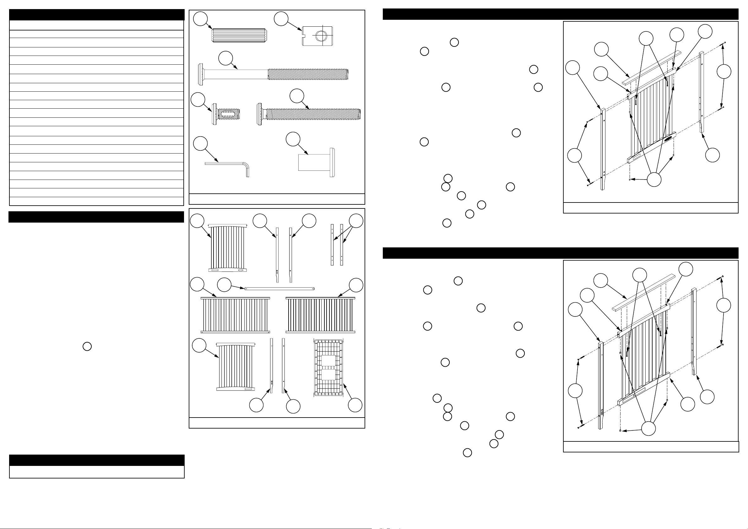
PARTS LIST
Part Description Part Number Quantity
A. Dowel Pin 10mm x 40mm
B. Joint Connector Nut 1/4-20
C. Allen Head Bolt 80mm 1/4-20
D. Allen Head Bolt 14mm 1/4-20
E. Allen Head Bolt 55mm
F. Allen Wrench
G. Connector Nut
H. End Panel Footboard
I. Foot Post Left
J. Foot Post Right
K. Top Cap
L. Stretcher
M. Front Stationary Side
N. Back Stationary Side
O. End Panel Headboard
P. Head Post Left
Q. Head Post Right
R. Spring
PREPARATION
Carefully remove and lay out all hardware and parts.
Check quantities and match the parts list.
11200323
11200077
11200389
11200388
11200089
11200070
11200068
22301038
22301048
22301049
22301052
22301046
22301040
22301041
22301047
22301050
22301051
11200333
4
18
8
8
14
2
4
1
1
1
2
1
1
1
1
1
1
1
D
H
A
F
C
B
E
G
Hardware Package
I
J
AB20047_G3
K
STEP 1
Construct End Panel Footboard assembly:
Align Foot Post Left I onto dowel on End Panel
Footboard H Top Rail and push together making
sure slotted hole is on the inside opposite the
Childcraft logo. Place Joint Connectors Nut B into
holes in the bottom of top and bottom rail of End
Panel Footboard H . Insert Allen Head Bolts C into
Foot Post and rotate Joint Connector Nuts to align
threads with bolts. Snug Bolts and Connectors with
Allen wrench .
Repeat procedure with Foot Post right J . Note Foot
Post Right J has no slotted holes.The (3) through
holes in the face have a counterbored (larger) entry
hole which will be located on the same face as the
childcraft logo
Insert Dowel Pins A into outer holes on top of End
Panel Footboard H . Place Top Cap K on top of
End Panel Footboard H and align with the Dowel
Pin. Insert Allen Head Bolts E into underside of top
of End Panel Footboard H then thread into metal
inserts in top cap K .
Tighten all bolts securely.
See gure 1.
I
C
K
A
E
B
Figure 1
A
H
C
J
AB20047_G5
Construct Crib on an even at oor.
Note: during the assembly process whenever
using screws or bolts, Check each with the parts list
by letter and size identication. Place each screw
or bolt on the diagram of the item which is sketched
actual size. Be sure to use the proper size specied
in the assembly directions. If any parts are missing
or broken or you need assistance with assembly
The Allen Head Bolts D have a friction enhancing
patch on the thread which may cause resistance
during tightening.
DO NOT return your product to the dealer.
Please identify the crib by the model number
identication stamped on the inside face of the
Stationary side assembly when you call or write to
Foundations®. Make note of all identification
numbers and include this information with your
request.
DO NOT Substitute Parts!
SUGGESTED TOOLS
#2 Medium Straight Screwdriver
STEP 2
Construct End Panel Headboard assembly:
M
L
N
O
P
Crib Parts
2 3
Q
AB20047_G4
R
Align Head Post Left P onto dowel on End Panel
Headboard O Top rail and push together making
sure slotted hole is on the inside.
Place Joint Connector Nuts B into holes in the
bottom of top and bottom rail of End Panel
Headboard O Insert Allen Head Bolts C into Head
Post and Rotate Joint Connectors Nuts to align
threads with bolts and snug with Allen wrench .
Repeat procedure with Head Post right Q . Note
Head Post Right Q has no slotted holes. The (3)
through holes in the face have a counterbored
(larger) entry hole which will be located on the
outside face (opposite face from slotted hole in
Head Post left P ).
Insert Dowel Pins A into outer holes on top of End
Panel headboard O .Place Top Cap K on top of
End Panel Headboard O and align with the Wooden
dowel Pin. Insert Allen Head Bolt E into underside
of top of End Panel Headboard H . Then thread into
metal inserts in top cap K .
Tighten all bolts securely.
See gure 2.
P
C
A
K
A
E
C
Q
O
B
AB20047_G6
Figure 2
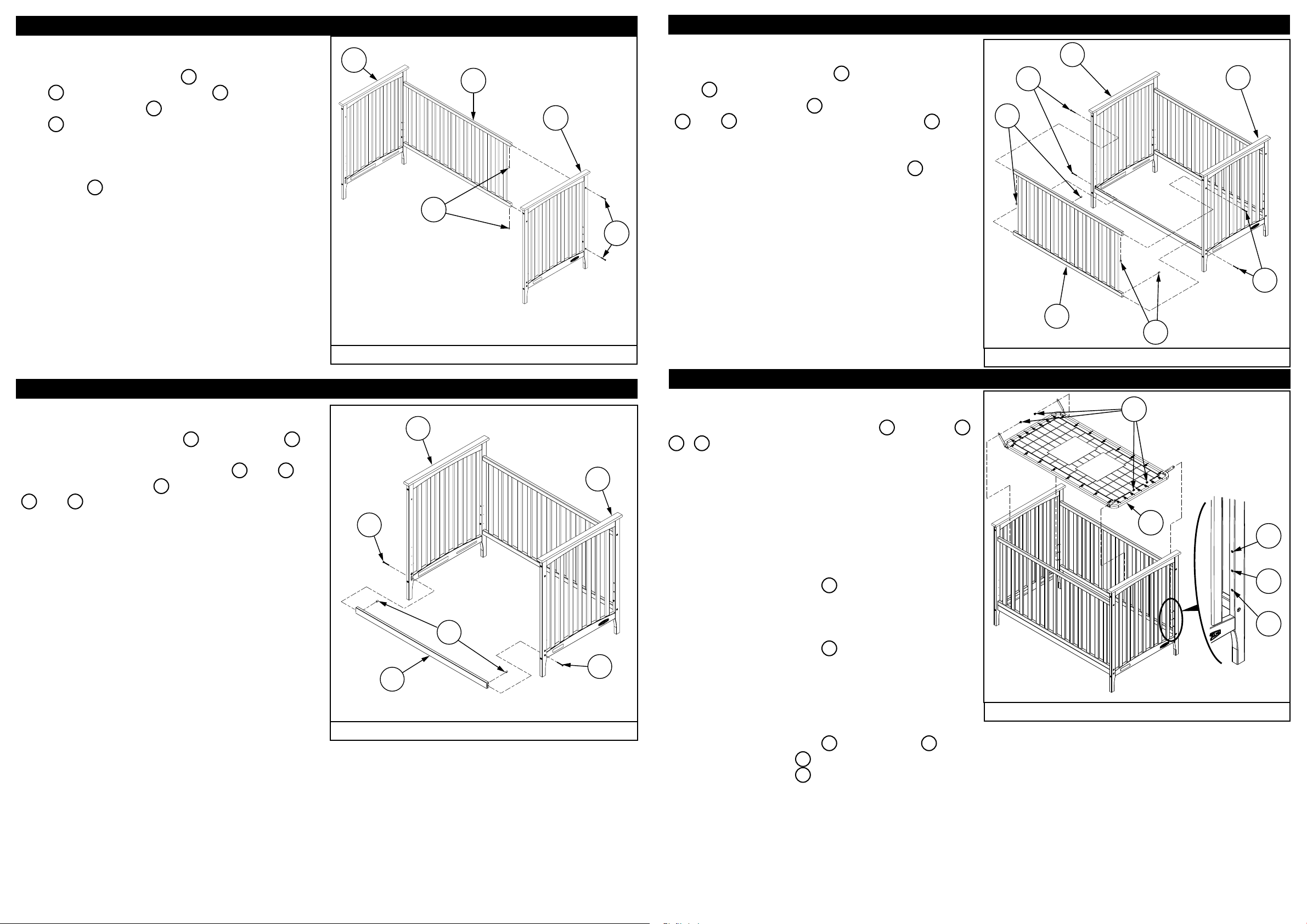
STEP 3
Assemble End Panels to Back Stationary Side.
O
Insert Joint Connector Nuts B into Back Stationary
Side N . Insert Allen Head Bolts E into Finished
End Panel Footboard H . Rotate Joint Connector
Nuts B to align threads with bolts and snug with
Allen wrench .
N
H
STEP 5
Assemble Front Stationary Side to crib.
Insert Joint Connector Nuts B into Front Stationary
Side M .
Insert Allen Head Bolts E into Finished End Panels
O and H . Rotate Joint Connectors Nuts B to
align threads with bolts and snug with Allen wrench.
B
E
O
H
Repeat procedure with nished End Panel
Headboard O .
Tighten all bolts securely.
See gure 3.
STEP 4
Assemble Stretcher to crib.
Insert Joint Connector Nuts B into Stretcher L .
Align and insert tenons on end of stretcher into
slotted holes in Finished End panels O and H .
Insert Allen Head Bolts E into Finished End Panels
O and H . Rotate Joint Connectors Nuts to align
threads with bolts and loosely tighten with Allen
wrench.
E
O
B
Figure 3
H
E
Tighten all bolts securely including Bolts E at
stretcher which were not fully tightened during
step 4
See gure 5
STEP 6
Add Mattress Spring to crib.
There are 3 positions for the Spring R shown as 1
2 , 3 . Refer to warning section to determine
appropriate height for the intended child. The
position must be the same as for all the brackets
attached to the crib.
Note: Pouches containing warnings and instructions
face up on top surface of Spring.
M
B
Figure 5
D
R
E
AB20047_G9
3
Do Not tighten bolts securely until end of step 5.
See gure 4.
Position tabs on Spring at approximately a 45
degree angle. The Spring R is lowered into the
crib. Take care not to scratch the wood with the
metal spring. Align the Spring Brackets with the
B
E
L
AB20047_G8
Figure 4
4 5
holes in the crib at the
desired height. Insert Bolt D into hole in spring
brackets from inside of crib then through correct
height hole in the crib.
Tighten all bolts securely with Allen wrenches.
To Adjust height of Spring R remove bolts D .
Then relocate Spring R to new height adjustment
level and install Bolts D as described in previous
paragraph.
See gure 6.
2
1
AB20047_G10
Figure 6
 Loading...