

Page 1
CCH00701:09/00 JCHE p65
DOUBLE DROPSIDE CRIB
child craftchild craft
child craftchild craft
child craft
CHILD CRAFT INDUSTRIES, INC.
P.O. Box 444, Salem, IN USA 47167-0444
PH: 812-883-3111 - FAX: 812-883-1819 - http://www.childcraftind.com
ASSEMBLY DIRECTIONS AND PARTS LIST
ΦREAD ALL INSTRUCTIONS WITH CARE BEFORE STARTING THE ASSEMBLY PROCEDURE.
ΦΦ
ΦΦ
ΦYOU WILL NEED A #2 PHILLIPS SCREWDRIVER, A SLOTTED SCREWDRIVER AND A HAMMER.
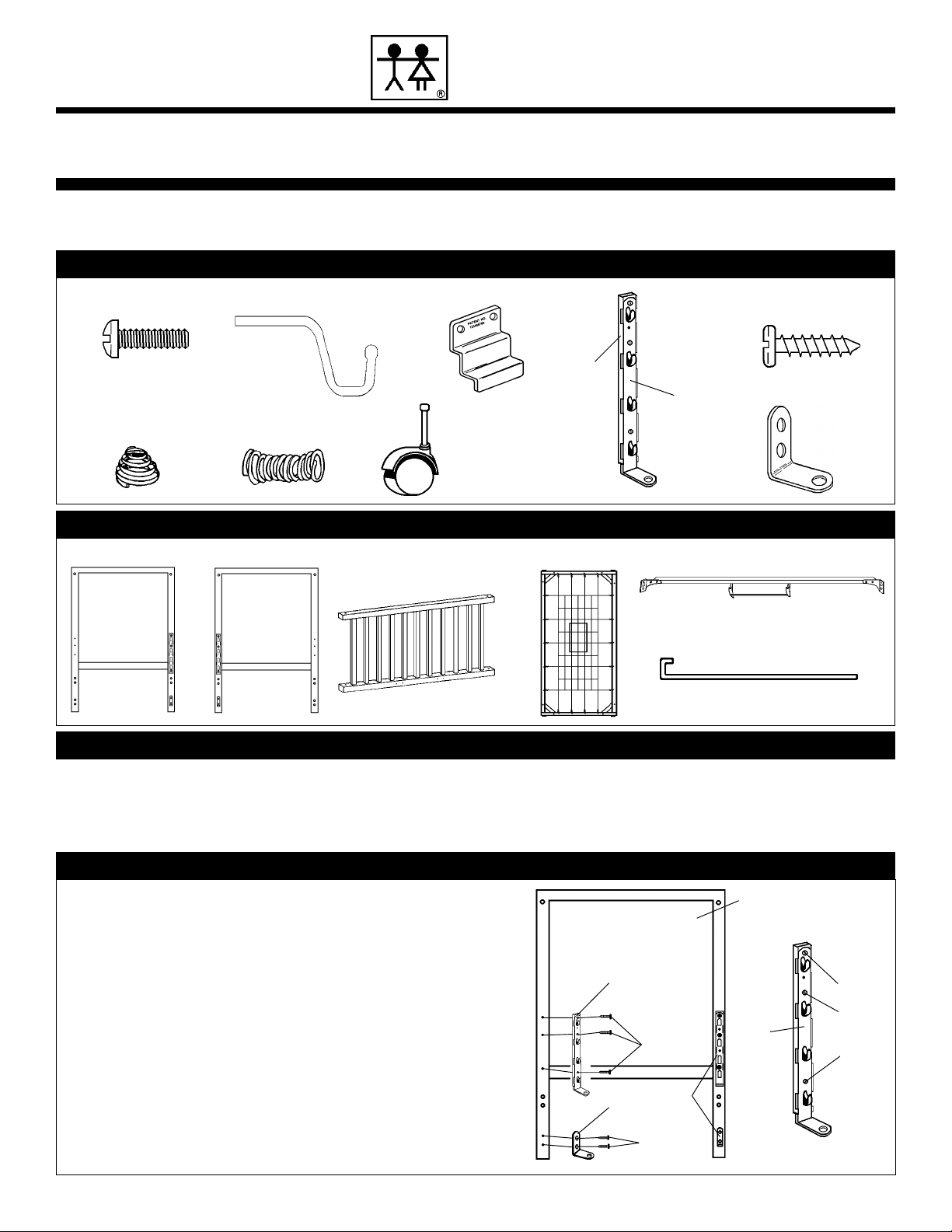
PARTS ENCLOSED IN HARDWARE BAG (NOTED WHEN SHOWN ACTUAL SIZE)
(18) Slotted/Phillips
Wood Screws
EE
EE
E
(12) Slotted/Phillips
Machine Screws
AA
AA
A
(actual size)
BB
BB
B
(4) Spring Hangers
CC
CC
C
(4) Gate Shoes
DD
DD
D
(2)
Moulded
plastic
backers
(2)
4-Position
Spring
Hanger
Brackets
(actual size)
FF
FF
F
(4) Compression
Springs
GG
GG
G
(4) Bumper
Springs
HH
HH
H
(4) Casters
(style may vary)
II
II
I
(2) Angle
Brackets
PARTS INCLUDED IN CARTON
OO
OO
O
(1) Footboard
NN
NN
N
(1) Headboard
PP
PP
P &
QQ
QQ
Q
(2) Crib sides
(Dropsides)
RR
RR
R
(1) Spring
JJ
JJ
J
(2) Stabilizer Bars
KK
KK
K
(4) Crib Rods
PREPARATION
Carefully remove and lay out all hardware and parts. Remove wires securing the (2) Stabilizer Bars
JJ
JJ
J and the (4) Crib Rods
KK
KK
K to Crib Spring
RR
RR
R. Check
quantities and match to the three Parts Lists above. If any part is missing or broken contact your dealer or Child Craft (P.O. Box 444, Salem, IN 471670444 USA (ph# 812/883-3111), [email protected] for a replacement part or instructional literature. Before making this contact, identify your crib.
A model identification number is stamped on the underneath side of the bottom rail of either a crib end
NN
NN
N/
OO
OO
O or a crib side
PP
PP
P/
QQ
QQ
Q. Record the model
Identification Number now: # ______________________. Include this number with a request for a part or instructional literature. DO NOT SUBSTITUTE
PARTS!
Note the two piece assembly of 4-Position Spring Hanger Brackets
DD
DD
D. Before
attachment to crib
(ends)
NN
NN
N &O, check to be sure the moulded plastic backer
aligns with the 4-Position Spring Hanger Bracket
DD
DD
D as shown. These items are
shipped assembled, in the unlikely event they should become detached during
shipment, simply take the plastic backer, align with the holes in the metal bracket
and snap together to create an assembly as shown in the Hardware Parts Diagram.
IMPORTANT! All four plastic tabs on each moulded plastic backer should project
toward the metal hooks on 4-Position Spring Hanger Brackets
DD
DD
D. If you should
find a tab on an uninstalled 4-Position Spring Hanger Bracket not so projected,
simply use a screwdriver to push tab forward until it contacts the metal hook. If
a plastic tab is not projected on a factory installed 4-Position Spring Hanger Bracket
simply place a small slotted screwdriver underneath the plastic tab and pull
forward until it contacts the metal hook. Attach a 4-Position Spring Hanger Bracket
DD
DD
D,
(2 piece assembly)
, to both Headboard
NN
NN
N & Footboard
OO
OO
O with Slotted/Phillips
Wood Screws
EE
EE
E, to be positioned exactly as the ones already factory installed.
Attach Angle Brackets
II
II
I with Slotted/Phillips Wood Screws
EE
EE
E to Headboard
NN
NN
N
and Footboard
OO
OO
O, to be positioned exactly as the ones already factory installed.DO
NOT REMOVE 4-POSITION SPRING HANGER BRACKETS OR ANY OTHER
HARDWARE ITEM ATTACHED WITH SLOTTED/PHILLIPS WOOD SCREWS
EE
EE
E.
STEP 1 - DIAGRAM 1: ATTACH OF 4-POSITION SPRING HANGER BRACKETS AND ANGLE BRACKETS.
EE
EE
E
EE
EE
E
II
II
I
DD
DD
D
Factory
installed
OO
OO
O
Holes to
receive
Slotted/
Phillips
Wood
Screws
EE
EE
E
DD
DD
D
1
15061,16101,16151,16191,16281
Page 2
2
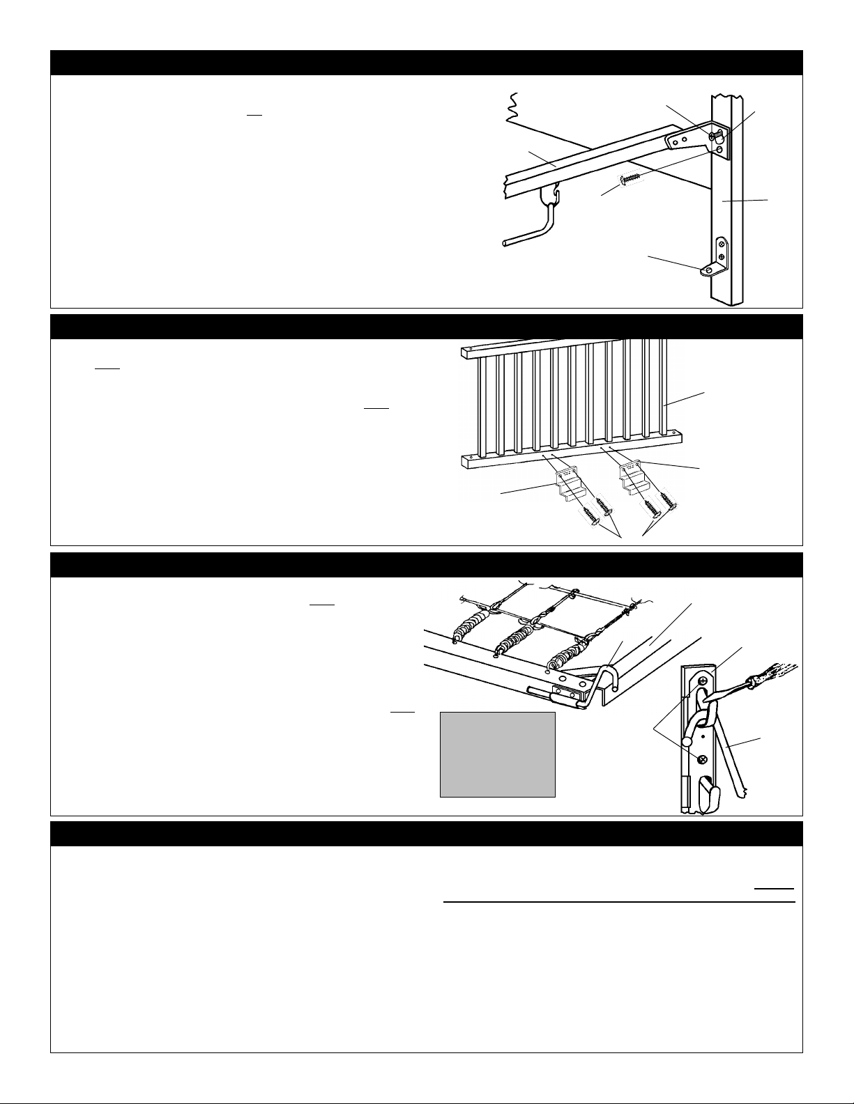
STEP 2 - DIAGRAM 2: INSTALL STABILIZER BARS.
Attach each Stabilizer Bar
DIAGRAM 6. You will use a total of (8) Slotted/Phillips Machine Screws
Slotted/Phillips Machine Screw
JJ
Bar
J placement, located in ends
JJ
- do not tighten at this time. Place the keyhole (top hole in each end of Stabilizer Bar
JJ
J, over top extended Screws
JJ
to Diagram. Ends
this procedure for mounting the remaining Stabilizer Bar
in the exact same manner. Place four Slotted/Phillips Machine Screws
receiving holes in each end of both Stabilizer Bars
NN
ends
OO
N &
O, tighten all eight Slotted/Phillips Machine Screws
NN
OO
NN
N and
NN
JJ
J to crib ends
JJ
AA
A into top receiving bushing, designated for Stabilizer
AA
OO
O &
OO
AA
A
(which you have just installed and left extended),
AA
OO
O will now be mounted together on one side of crib, repeat
OO
NN
OO
N and
O. Refer to Diagram 2 and MAIN
NN
OO
NN
N as shown, leave each top screw extended
NN
JJ
J to the other side of the crib
JJ
JJ
J, into receiving bushings located in
JJ
AA
A securely at this time.
AA
AA
A. Place a
AA
refer
AA
A into the lower
AA
STEP 3 - DIAGRAM 3: ATTACH GATE SHOES TO DROPSIDES.
EE
E.
EE
CC
C to lower rail
CC
CC
C over predrilled lead holes on lower rail
CC
and affix with (8) Slotted/Phillips Wood Screws
CC
C. Tighten Screws
CC
(inside)
of each Crib Side
EE
E securely. Note: When
EE
Position two Gate Shoes
shown. Note: Gate Shoe Patent No. will be visible when Gate Shoes
mounted. Align Gate Shoes
of Crib Side
EE
E, two in each Gate Shoe
EE
disassembling crib in the future, DO NOT REMOVE THE GATE SHOES
ANY OTHER HARDWARE ITEM ATTACHED WITH SLOTTED/PHILLIPS
WOOD SCREWS
P/QP/Q
P/Q
P/QP/Q
(dropsides)
P/QP/Q
P/Q as
P/QP/Q
CC
C are
CC
(inside)
CC
C OR
CC
J
A
A
Extended
I
Factory
installed
CCH00701:09/00
Keyhole
O
P orQ
STEP 4 - DIAGRAM 4: INSTALL SPRING HANGERS & CRIB SPRING
Locate Crib Spring
Spring Hangers
side of Crib Spring
6. Also the printing on the plastic pouch
placed upward. Insert Spring Hangers
frame of Crib Spring
required to fully engage Spring Hangers
RR
R by placing each of the 4 Spring Hanger
RR
of the four 4-Position Spring Hanger Brackets
backers), mounted on ends
The lip of the moulded plastic backer will allow the Spring Hanger to be
placed with no difficulty. However, when you decide on another placement
of Crib Spring
screwdriver, on the lip of the moulded plastic backer and hold down in order
to raise Spring Hanger
procedure whenever you opt to change Crib Spring
four positions.
RR
R,
(with plastic pouch factory attached)
RR
BB
B, refer to Main Diagram 6, and 4. Note: Be sure smooth
BB
RR
R wire is placed upward as illustrated in Main Diagram
RR
RR
R as shown, (a light blow with a hammer may be
RR
OO
O and
OO
RR
R you will need to place your thumbnail, or a small
RR
BB
B from its present position. Follow this same
BB
(attached to crib spring)
BB
B into each bracket attached to
BB
BB
B). Carefully install Crib Spring
BB
BB
B into a selected position in each
BB
DD
D, (with moulded plastic
NN
N. See Main Diagram 6, and 4. Note:
NN
DD
, and the four
RR
R to another of the
RR
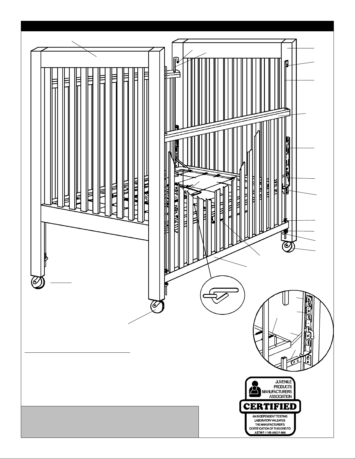
STEP 5: INSTALL CRIB DROPSIDES
Locate Crib Rods
Springs
a Crib Rod
to Main Diagram 6 for proper placement.)
GG
G and the four remaining Slotted/Phillips Machine Screws
GG
1.1.
1. The top rail of Crib Side
1.1.
KK
K, Crib Sides
KK
KK
K downward through the holes in the following sequence:
KK
(Note: gate shoes will be placed to inside),
2.2.
2. The L- bracket on 4-Position Spring Hanger Bracket
2.2.
3.3.
3. Compression Spring
3.3.
4.4.
4. Bottom Rail of Crib Side
4.4.
5.5.
5. A Bumper Spring
5.5.
6.6.
6. Hole in Angle Bracket
6.6.
GG
G,
GG
P/QP/Q
P/Q, Compression Springs
P/QP/Q
PP
QQ
P or
Q,
PP
FF
F,
FF
II
I.
II
(with plastic teething rail),
QQ
PP
QQ
P or
Q,
PP
QQ
FF
F, Bumper
FF
will be
AA
A. Insert
AA
(Refer
DD
D,
DD
C
C
E
RR
R
RR
BB
B
BB
Top surface
To remove Spring
Hanger
down on lip with
thumbnail or screwdriver and pull Spring
Hanger
Place a Slotted/Phillips Machine Screw
and into receiving bushing located in top corner post of Footboard
Headboard
USE A POWER SCREWDRIVER OF ANY TYPE TO TIGHTEN SCREW
Start Screw A (two or three turns) with your fingers into its threaded
bushing to insure Screw A has a square fit. Once you are sure Screw
A fits squarely into its threaded bushing, tighten securely with a hand
held screwdriver. Attach the other Crib Rod
Side
Machine Screws
tighten if needed.
suggest you rub the crib rod with waxed paper or paraffin. You may want
to repeat this procedure periodically. Attach the remaining Crib Side
or
BB
B press
BB
BB
B upward.
BB
NN
N
. Refer
to Main Diagram 6 for proper placement. DO NOT
NN
PP
QQ
P or
Q,, using the same procedure. Be sure Slotted/Phillips
PP
QQ
AA
A are tightened securely, check periodically and
AA
Tip:Tip:
Tip: To help Crib Rods
Tip:Tip:
QQ
Q, by repeating Step 5.
QQ
EE
E
EE
AA
A into hole in top of Crib Rod
AA
KK
K to the other end of Crib
KK
KK
K function more quietly we
KK
DD
D
DD
CLOSE UPCLOSE UP
CLOSE UP
CLOSE UPCLOSE UP
VIEW VIEW
VIEW
VIEW VIEW
BB
B
BB
KK
K
KK
OO
O/
OO
AA
A.
AA
PP
P
PP
Page 3
CCH00701:09/00
O
MAIN DIAGRAM 6
TIGHTEN SCREW
AA
A MANUALLY, DO NOT USE ANY TYPE OF POWER SCREWDRIVER.
AA
A
K
N
A
K
P / Q
Top rail
D
3
Locate the 4 Casters
lower corner post of Headboard
OO
O. Refer to Main Diagram 6.
OO
design may possibly vary according to your
particular crib model.)
CAUTION:
ally thick carpet, take care when crib is
rolled as Casters
carpet pile and possibly cause breakage
or damage to lower corner posts of crib.
If crib is placed on exception-
HH
H, insert each into a
HH
HH
H
could catch on thick
HH
NN
N/Footboard
NN
(Caster
HH
H
HH
H
Plastic
pouch
Hook end
CRIB SPRING
Be sure the smooth side of wire is
placed up as illustrated. Also,style
of Crib Spring
your model of crib.
RR
R:
RR
RR
R may differ with
RR
down
Foot latch
P / Q
Bottom rail
CLOSE UP VIEW
K
D
R
B
B
J
F
G
I
H
Permanent Storage of Assembly Instructions: After completing the assembly
process you are advised to read and be aware of all WARNINGS, CAUTIONS,
CLEANING, STORAGE, USE, and MAINTENANCE notices contained in this set of
assembly directions and printed on the plastic pouch located on the underneath side of
crib spring. You will then place this complete set of assembly directions into the plastic
pouch for future referral. We caution you not to place excess hardware in the plastic
pouch as it could present danger to a small child if retrieved.
Place a purchased mattress on Crib Spring
RR
R and crib is ready for use.
RR
TO RAISE & LOWER CRIB DROPSIDE: To lower lift the dropside
slightly, push the foot latch toward the inside of crib which will release
the dropside to the lowest or "DOWN" position. To raise the dropside,
lift up on the dropside, rail will then lock into the "UP" position.
J
N/O Corner Post
Page 4

4
WW
ARNINGARNING
W
ARNING
WW
!
▲
ΦΦ
ΦFAILURE TO FOLLOW THESE WARNINGS AND ASSEM-
ΦΦ
ARNINGARNING
CCH00701:09/00
BLY INSTRUCTIONS COULD RESULT IN SERIOUS INJURY
OR DEATH.
ΦΦ
ΦREAD ALL INSTRUCTIONS BEFORE ASSEMBLING CRIB.
ΦΦ
KEEP INSTRUCTIONS FOR FUTURE USE. A plastic pouch
is attached to crib spring for permanent storage of the
instructional literature.
ΦΦ
ΦBEFORE EACH USAGE OR ASSEMBLY, INSPECT CRIB
ΦΦ
FOR DAMAGED HARDWARE, LOOSE JOINTS, MISSING
PARTS OR SHARP EDGES. DO NOT USE CRIB IF ANY
PARTS ARE MISSING OR BROKEN. ASK YOUR DEALER OR
CHILD CRAFT, P.O. BOX 444, SALEM, IN 47167-0444 USA
(812/883-3111) [email protected] FOR REPLACEMENT PARTS AND INSTRUCTIONAL LITERATURE IF
NEEDED. INCLUDE MODEL IDENTIFICATION NUMBERS
WITH YOUR REQUEST WHICH YOU RECORDED ON PAGE
ONE. DO NOT SUBSTITUTE PARTS.
ΦΦ
ΦAFTER RAISING SIDE, MAKE SURE LATCHES ARE SE-
ΦΦ
CURE.
ΦΦ
ΦWHEN CHILD IS ABLE TO CLIMB OUT OR REACHES THE
ΦΦ
HEIGHT OF 35 INCHES (90 CENTIMETERS) THE CRIB SHALL
NO LONGER BE USED.
ΦΦ
ΦDO NOT PLACE CRIB NEAR WINDOW WHERE CORDS
ΦΦ
FROM BLINDS OR DRAPES MAY STRANGLE A CHILD.
ΦΦ
ΦIF REFINISHING, USE A NON-TOXIC FINISH SPECIFIED
ΦΦ
FOR CHILDREN'S PRODUCTS.
ΦΦ
ΦDO NOT LEAVE CHILD IN CRIB WITH SIDE LOWERED. BE
ΦΦ
SURE SIDE IS IN RAISED AND LOCKED POSITION WHENEVER CHILD IS IN CRIB.
ΦΦ
ΦWHEN CHILD IS ABLE TO PULL TO STANDING POSITION,
ΦΦ
SET MATTRESS TO LOWEST POSITION AND REMOVE
BUMPER PADS, LARGE TOYS AND OTHER OBJECTS THAT
COULD SERVE AS STEPS FOR CLIMBING OUT.
ΦΦ
ΦNEVER USE PLASTIC SHIPPING BAGS OR OTHER PLAS-
ΦΦ
TIC FILM AS MATTRESS COVERS BECAUSE THEY CAN
CAUSE SUFFOCATION.
ΦΦ
ΦDO NOT USE A WATER MATTRESS WITH THIS CRIB.
ΦΦ
ΦΦ
ΦREPLACE TEETHING RAIL(S) IF DAMAGED OR LOOSE.
ΦΦ
ΦΦ
ΦSTRINGS CAN CAUSE STRANGULATION! DO NOT PLACE
ΦΦ
ITEMS WITH A STRING AROUND A CHILD'S NECK, SUCH
AS HOOD STRINGS OR PACIFIER CORDS. DO NOT SUSPEND STRINGS OVER A CRIB OR ATTACH STRINGS TO
TOYS.
ΦΦ
ΦREMOVE ALL CRIB TOYS WHICH ARE STRUNG ACROSS
ΦΦ
CRIB AREA WHEN YOUR CHILD IS BEGINNING TO PUSH
UP ON HANDS AND KNEES OR IS 5 MONTHS OF AGE,
WHICHEVER OCCURS EARLIEST. THESE TOYS CAN
CAUSE STRANGULATION!
CAUTIONCAUTION
CAUTION
CAUTIONCAUTION
ΦΦ
ΦANY MATTRESS USED IN THIS
ΦΦ
CRIB MUST BE AT LEAST 27-1/4
INCHES (69 CENTIMETERS), BY 515/8 INCHES (131 CENTIMETERS),
WITH A THICKNESS NOT EXCEEDING 6 INCHES (15 CENTIMETERS).
the dimensions of the mattress shall
be taken from seam to seam or edge
to edge where appropriate.
ΦΦ
ΦUPON COMPLETION OF ASSEM-
ΦΦ
BLY BE SURE ALL SCREWS,
BOLTS AND FASTENING DEVICES
HAVE BEEN TIGHTENED SECURELY. A FREQUENT CHECK
SHOULD BE MADE OF ALL
SCREWS, BOLTS AND FASTENING
DEVICES AND TIGHTEN IF
NEEDED.
MAINTENANCE OF YOUR CHILD CRAFT CRIB:
completion of assembly be sure all screws, bolts and
fastening devices have been tightened securely. A
frequent periodic check should be made of all screws,
bolts and fastening devices and tighten if needed. Before
each usage or assembly, inspect crib for damaged
hardware, loose joints, missing parts or sharp edges. DO
NOT use crib if parts are missing or broken. Ask your
Dealer or Child Craft (812/883-3111),
[email protected] for replacement parts and
instructional literature if needed. Include Model Identification Number with your request which you recorded on
page 1. DO NOT substitute parts. DO NOT make any
alteration to this crib.
CLEANING INSTRUCTIONS FOR YOUR CHILD CRAFT
CRIB:
Mix together a mild solution of gentle dishwashing
liquid and water, apply to crib surface using a soft clean
cloth lightly dampened in the solution. Rinse with clear
water again using a soft clean cloth then dry all surfaces
thoroughly with a soft dry cloth. NO ABRASIVE CLEAN-
ERS, SCOURING PADS, STEEL WOOL, OR COARSE
RAGS SHOULD BE USED TO CLEAN THIS FINE FURNITURE.
STORAGE AND USE OF YOUR CHILD CRAFT CRIB:
printed plastic pouch is attached to the crib spring for the
permanent storage of the assembly directions. After
completing the assembly process you are advised to
read and be aware of all WARNINGS, CAUTIONS, CLEANING, STORAGE, USE AND MAINTENANCE notices contained in this set of assembly directions and printed on
the plastic pouch located on the underneath side of crib
spring. You will then place the complete set of assembly
directions into the plastic pouch for future referral. We
caution you not to place excess hardware in the plastic
pouch as it could present danger to a child if retrieved and
it could also puncture crib mattress. When storing crib
use CAUTION as extreme temperature or humidity
changes could be harmful. Use CAUTION when a vaporizer is in use, always aim vaporstream away from crib
as well as away from any other wood furniture item.
Upon
CCH00701:09/00 JCHE p65
made in usa
A
ΦΦ
ΦWHEN DISASSEMBLING THIS CRIB, DO NOT REMOVE
ΦΦ
ANY ITEM ATTACHED WITH WOOD SCREWS.
ΦΦ
ΦALWAYS ENSURE A SAFE ENVIRONMENT FOR THE
ΦΦ
CHILD BY CHECKING REGULARLY, BEFORE PLACING
THE CHILD IN THE CRIB, THAT EVERY COMPONENT IS
PROPERLY AND SECURELY IN PLACE.
CHILD CRAFT INDUSTRIES, INC.
P.O. Box 444, Salem, IN USA 47167-0444
PH: 812-883-3111 - FAX: 812-883-1819
http://www.childcraftind.com
 Loading...