

Page 1

BMW X3 Adapters
Add-On Package
A DOVER COMPANY
USERS MANUAL
Chief Automotive Technologies
Page 2

Page 3

BMW X3 Adapters
USERS MANUAL
Introduction
The BMW X3 Adapter Add-On Package is designed as an
add-on package to the BMW Clamping Adapters Without Side
Jack Lifting Holes, Part Number 519638. It is not a stand
alone anchoring package. For additional details, see the
users manual for the BMW Clamping Adapters Without Side
Jack Lifting Holes.
CHIEF'S LIMITED ONE-YEAR
WARRANTY & LIABILITY
Chief Automotive Technologies warrants for one year from the date of installation and/or
purchase any of its products which do not perform satisfactorily due to defect caused by faulty
material or workmanship. Chief's obligation under this warranty is limited to the repair or
replacement of products which are defective and which have not been misused, carelessly
handled, or defaced by repairs made or attempted by others.
CHIEF AUTOMOTIVE TECHNOLOGIES DOES NOT ASSUME
RESPONSIBILITY FOR ANY DEATH, INJURY OR PROPERTY
DAMAGE RESULTING FROM THE OPERATOR'S NEGLIGENCE OR
MISUSE OF THIS PRODUCT OR ITS ATTACHMENTS. CHIEF MAKES
NO WRITTEN, EXPRESS OR IMPLIED WARRANTY WHATSOEVER
OF MERCHANTABILITY OR FITNESS FOR A PARTICULAR PURPOSE
OR OTHERWISE REGARDING THE EQUIPMENT OR ANY PART OF
THE PRODUCT OTHER THAN THE LIMITED ONE-YEAR WARRANTY
STATED ABOVE.
1
Page 4

BMW X3 Adapters
USERS MANUAL
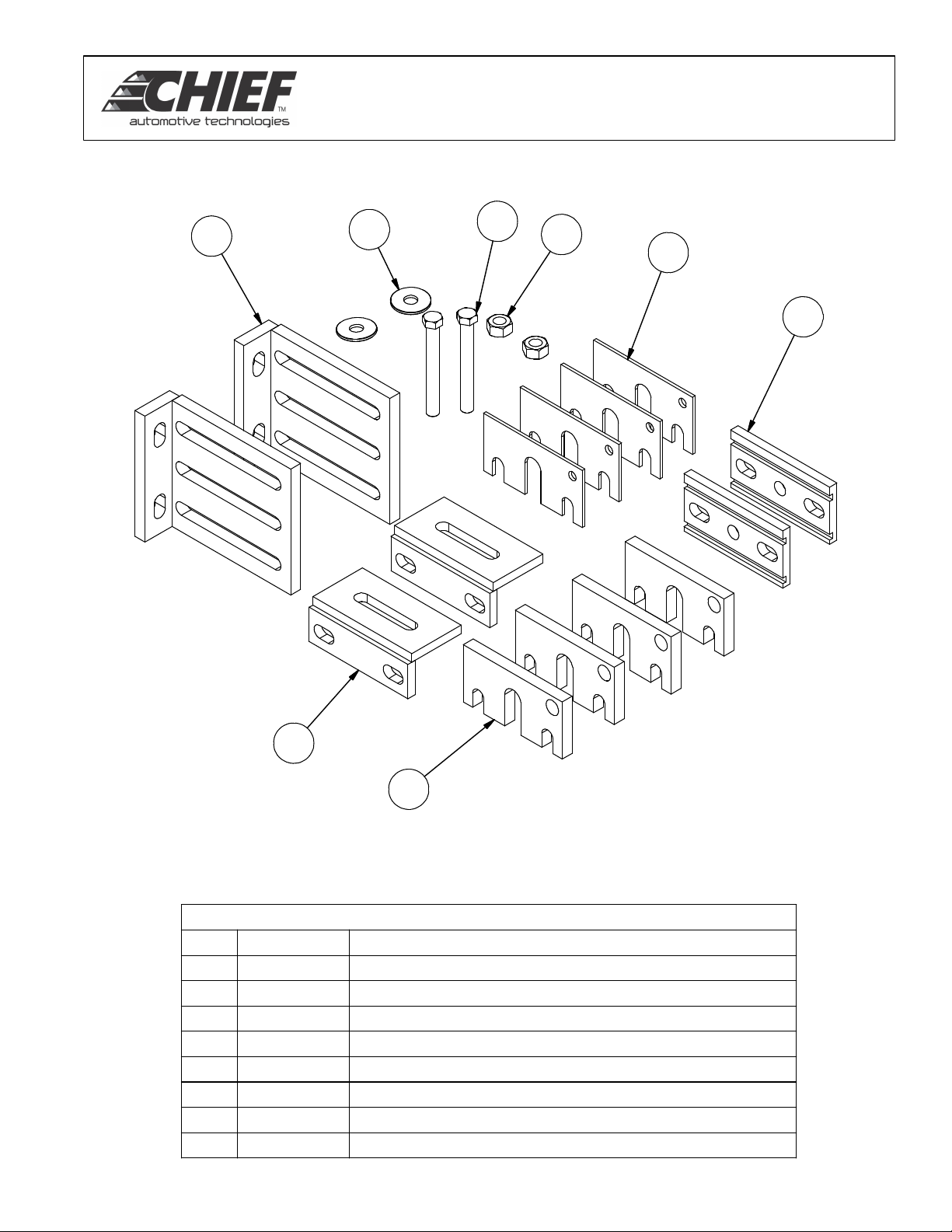
Half Clamp
Round Spacer
With Oval Inset
Oval Hole
Attachment
REAR
Small Angle
Support
Drain Channel
Spacer
FRONT
10 Ga Shim
.5 Shim
Large Angle
Support
2
Page 5

BMW X3 Adapters
USERS MANUAL
BMW X3 Clamping Instructions (Refer to
illustrations on page 3).
1. Remove oval hole pulgs and plastic shields
under vehicle's rocker panels. Also remove
reinforcements from rear differential to rocker
panels.
2. Remove clamp jaws from anchoring stand.
3. Attach a large angle support to rear of each
front anchoring stand (see page 3).
NOTE: Attach supports to outside surface of
anchoring stand's vertical plate as shown.
Attach a large angle support to front of each rear
anchoring stand. Repeat process for front
anchoring stand.
Note: Attach supports to inside surface of
anchoring stand's vertical plate as shown.
4. Attach a small angle support to the rear of
each rear anchoring stand (see page 3).
NOTE: Attach supports to inside surface of
anchoring stand's vertical plate as shown.
5. Position oval hole attachment and spacer
with oval hole inset on top of each large angle
support mounted to front stands (see page 3).
Then position oval hole insert on top of each
large angle support mounted to rear stands (see
page 3). Threaded portion of oval hole
attachments must project downward through
spacer and through middle slot on front stands
and through rear slot on rear stands.
6. Use appropriate lifting device to elevate one
side of the vehicle and position front anchoring
stands so that the oval hole attachment is
aligned with the oval hole in the bottom of the
rocker panel.
CAUTION: Grip threaded portion of oval hole
attachment when aligning attachment with oval
hole in rocker panel. DO NOT place hands
between the rocker panel and anchoring
components.
7. Lower venicle so that oval hole attachment
engages oval hole in bottom of rocker panel.
Then grip threaded end of oval hole attachment
to push attachment upward. Rotate attachment
90 degrees
so that it straddles inside of oval hole in rocker
panel and use 1/2 inch nut and washer to secure
the anchoring stand to the rocker panel.
NOTE: To verify a secure hold, slightly raise
vehicle. If stand also raises, it is secure. If it
dosen't lower vehicle and repeat step 7.
8. Secure half clamp jaw to inside large angle
support, using two thick shims, one thin shim and
one drain channel spacer (see page 3). Engage it
with the horizontal pinchweld flange in the process.
9. Repeat Steps 6-8 on opposite side of vehicle.
10. To install rear anchoring stand, elevate side of
vehicle and position rear anchoring stands so that
the oval hole attachment is aligned with the oval
hole in the bottom of the rocker panel (see page 3).
CAUTION: Grip threaded portion of oval hole
attachment when aligning attachment with oval hole
in rocker panel. DO NOT place hands between the
rocker panel and anchoring components.
11. Lower vehicle so that oval hole attachment
engages oval hole in bottom of rocker panel. Then
use threaded end of oval hole attachment to push
attachment upward. Rotate attachment 90 degrees
so that it straddles inside of oval hole in rocker
panel and use 1/2 inch nut and washer to secure
the anchoring stand to the rocker panel.
NOTE: To verify a secure hold, slightly raise
vehicle. If stand also raises, it is secure. If it
dosen't lower vehicle and repeat step 11.
12. Secure small angle support to rocker panel
using existing bolt from the reinforcement bar and a
washer (see page 3).
13. Repeat Steps 6-12 on opposite side of
vehicle.
3
Page 6
BMW X3 Adapters
USERS MANUAL
1
5
8
4
2
7
5
7
6
5193142
539025
3
Parts List
DESCRIPTIONP/NITEM
SUPPORT, MAIN, SLOTTED5196321
SHIM, 10 GAGE (.135) HONDA 2004
SHIM, .500, HONDA 20045193153
Nut, M12 x 1.75 Hex5390244
WASHER, FLAT, M12 X 1.75
CLAMP SUPPORT FOR BMW X35196516
Drain Channel Spacer514670
Bolt, M12 x 2.5 x 100mm Hex0133148
4
Page 7

Page 8

P.O. Box 1368
Grand Island, Nebraska 68802-1368
Phone: 308/384-9747
Fax: 308/384-8966
www.chiefautomotive.com
Chief reserves the right to alter product specifications
and/or package components without notice.
519465 REV 2/08
2007 ©Chief Automotive Technologies
 Loading...