

Page 1
I N S T A L L A T I O N I N S T R U C T I O N S
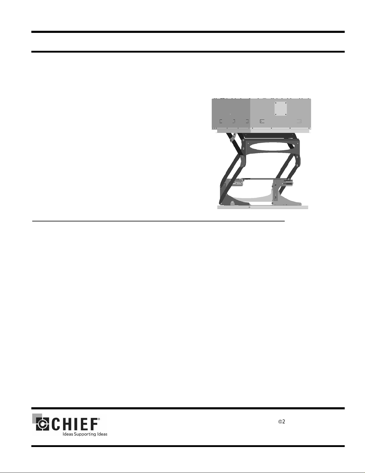
SMART-LIFTTM 236 Electric Ceilin g Lift
The Model SL-236 Electric Ceiling Lift is a reliable,
heavy-duty video lift mechanism for LCD/DLP projectors
requiring an extended drop from their hidden location.
The ceiling lift is designed for home-theater, conference
room, or school applications.
The SL-236 provides an attractive solution to recess a
projector in the ceiling. Th e lift is suitable for finis hed or
suspended ceiling with a finish kit. The concealed bottom
can be finished to match existing ceiling design and color
to conform to room decor.
Plenum Rating requires use of Class II control wiring,
electrically hard wiring the unit, and all open holes in the
housing (except joist tabs) must be sealed using foil tape.
BEFORE YOU BEGIN
• CAUTION: To prevent damage to the ceiling lift, which could affect or void the factory warranty, thoroughly study
all instructions and illustrations before you begin to install or operate the lift. Pay particular attention to the “Important Precautions” on Page 1.
• CAUTION: For smooth and reliable operation, the lift must be installed square and parallel in all dimensions. Avoid
stressing or twisting the lift at any time during installation.
• Because of the size and weight of the lift, Chief Manufacturing recommends that at least two people be available
when installing the lift.
• If you have any questions concerning this installation, contact Chief Manufacturing at 1-800-582-6480.
CHIEF MANUFACTURING INC.
1-800-582-6480 952-894-6280 FAX 952-894-6918
8401 EAGLE CREEK PARKWA Y
SA VAGE, MINNESOTA 55378 USA
PART NO. 8820-000008 (Rev.
©
2008 Chief Manuf acturing
www
.chiefmfg.com
0
4-08
E)
Page 2

Instruction Manual SMART-LIFT 236 Electric Ceiling Lifts
IMPORTANT WARNINGS AND CAUTIONS!
• WARNING: This is an electrical device. All electrical installation proced ures should be performed by a qualified electrician.
• WARNING: Improper installation can result in serious personal injury! Make sure that the ceiling structural members can support a redundant weight factor five times
this weight, reinforce the ceiling before installing the lift.
• WARNING: Be aware during the installation that this is a motorized device, and there are pinch points for people and
for el ectrical wiring.
• W ARNING: Be aware of the potential for pers onal injury or damage to the lift if it is not adequately mounted. The lift
(without a projector) weighs approximately 85 lbs (38.5 kg).
• W ARNING: Plenum rating r equire s the unit to be hard wired through the pr ovided strain r elief, use of Clas s II control
wiring, and all open holes in housing (except joist tabs) must be sealed using foil tape.
• WARNING: Electrical outlets must be install ed by a qualified electrician. Follow all electrical codes.
• CAUTION: Test the lift for shipping damage. See “PRETEST THE LIFT BEFORE INSTALLING” on page 6.
the total weight of the equipment. If the ceiling can not support
• CAUTION: For smooth and reliable operation, the lift must be ins tal led square and parallel in all dimensions. Avoid stress-
ing or twisting the lift at any time during installation.
• CAUTION: Changes or modifications not approved by Chie f Manufacturing could void use r’s warranty.
• CAUTION: Improper weight distributio n could lead to equipment damage. Make certain projector weight is centered on cra-
dle when mounted.
TOOLS REQUIRED FOR INSTA L LATION
• Phillips screwdrivers, No. 1 and No. 2
• Electric drill and bit set
• Pliers (heavy -duty)
• Electrical wire cutter/stripper
• If suspende d from threaded rods: Socket set with extension and open wrenches
NOTE: Other tools may be required depending on the
method of installing the lift in the ceiling.
1
Page 3

Instruction Manual SMART- LIFT 236 Electric Ceiling Lifts
CONTENTS
DIMENSIONAL DRAWING ................................................................... 3
SPECIFICATIONS ................................................................................. 4
ACCESSORIES ..................................................................................... 5
PRETEST THE LIFT BEFORE INSTALLING ........................................ 6
PREPARE THE CEILING OPENING AND
INSTALL THE LIFT ............................................................................... 7
General Guidelines ................................................................... 7
Installation in a Suspe nded Ceiling (using threaded ro ds) ....... 8
Installation in a Wood Framework (or Side-Mounted to Joists) 9
CONNECT POWER TO THE LIFT ........................................................10
Non Plenum Rated Installation .................................................10
Plenum Rated Installation ......................................................... 10
(OPTIONAL) INSTALLING WIRING COVER..........................................11
INSTALL THE PROJECTOR ON THE LIFT ..........................................12
Install and Route Cables ........................................................... 12
ADJUSTMENTS .................................................................................... 13
Adjust Travel .............................................................................13
Adjust the Aim of the Projector ................................................. 13
OUTSIDE TERMINAL WIRING EXAMPLES ......................................... 14
Push Button ..............................................................................14
Supplied SPST Switch Using Internal 24VAC Power Supply ... 14
Supplied SPST Switch Using Internal 12VDC Power Supply ... 14
Supplied SPST Switch Using External Power Supply .............. 14
SPDT Switch or 2 Dry Contact Closures, Momentary or
Latching ....................................................................................15
Internal 12VDC Power Supply 2.5A Maximum .........................15
Internal 24VAC Power Supply, 1.2A Max ................................. 15
Internal Dry Contact Closures....................................................15
Service Position ........................................................................ 15
INSIDE TERMINAL WIRING EXAMPLES .............................................16
Push Button ..............................................................................16
Supplied SPST Switch Using Internal 24VAC Power Supply ... 16
Supplied SPST Switch Using Internal 12VDC Power Supply ... 16
Supplied SPST Switch Using External Power Supply .............. 16
SPDT Switch or 2 Dry Contact Closures, Momentary or
Latching ....................................................................................17
Internal 12VDC Power Supply 1.2 A Maximum ........................ 17
Internal 24VAC Power Supply, 2.5 A Maximum ....................... 17
Internal Dry Contact Closures ...................................................17
Low Voltage Sensing: ...............................................................17
Service position..........................................................................17
INTERIOR TERMINAL DESIGNATIONS .............................................. 18
EXTERIOR TERMINAL DESIGNATIONS ............................................. 20
TROUBLESHOOTING .......................................................................... 22
2
Page 4
Instruction Manual SMART-LIFT 236 Electric Ceiling Lifts
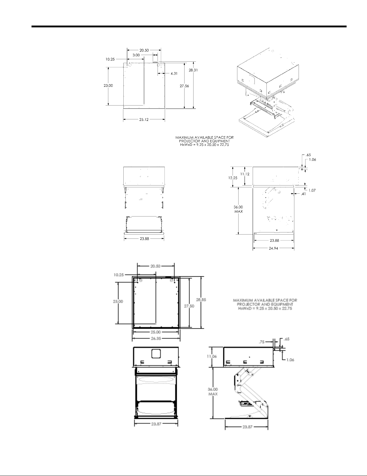
DIMENSIONAL DRAWING
SP
FD
3
Page 5

Instruction Manual SMART-LIFT 236 Electric Ceiling Lifts
SPECIFICATIONS
OVERALL DIMENSIONS CLOSED (HxWxD): FD: 11.0 6 x 26.35 x 28. 85
SP: 12.25 x 25.12 x 28.31
MAXIMUM AVAILABLE SPACE FOR
PROJECTOR AND EQUIPMENT (HxWxD): 9.25 x 20.50 x 22.75
CLOSURE PANEL SIZE (WxD): 23.87 x 23.87
RECOMMENDED CEILING OPENING SIZE (WxD)*: 25.50 x 28.00
AVAILABLE TRAVEL DISTANCE: 36.00"
ROLL ADJUSTMENT: 2°
PITCH ADJUSTMENT: 15°
YAW ADJUSTMENT: 10°
INTERNAL HEIGHT ADJUSTMENT: 2.00"
INTERNAL FORE/AFT ADJUSTMENT: 3.00" (1/2" INCREMENTS)
INTERNAL LEFT/RIGHT ADJUSTMENT: 2.00" (1/2" INCREMENTS)
COLOR: WHITE
MAXIMUM WEIGHT CAPACITY: 35#
NET WEIGHT: 85#
OUTPUT RELAYS: 1.0 AMP@30VDC
0.5 AMP@125VAC
0.3 AMP@60VDC
INTERNAL POWER SUPPLY: 12VDC, 2.5A MAX
24VAC, 1.2A MAX
CURRENT DRAW: .75A
FUSE: 4A, BUSSMAN TYPE GDB
*A NOTCH MAY BE REQUIRED TOW ARD THE REAR OF THE OPENING TO CLEAR THE TERMINAL BLOCK. SEE
DIMENSIONAL DRAWINGS.
4
Page 6
Instruction Manual SMART-LIFT 236 Electric Ceiling Lifts
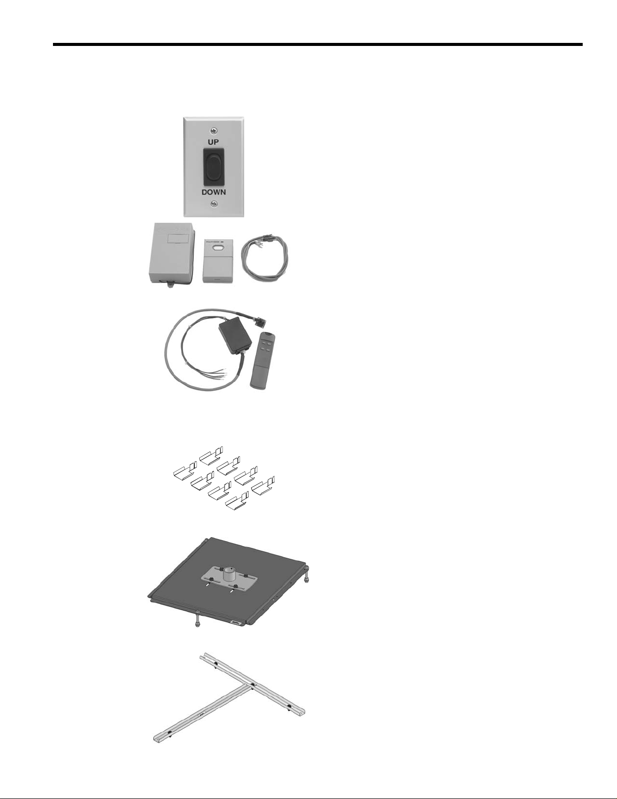
ACCESSORIES
Control
ASP-401
Rocker Switch with Wall Plate
Simple lift control.
RC-10
Radio Frequency
Remote Control
IR-10
Infra-Red Remote Control
Multiple code settings.
Single button control of the lift.
SMA-620
Suspended Ceiling Track
Clip
SMA-601
Single Column Mounting Plate
Discrete UP/DOWN/SERVICE comm an ds .
Used with most universal remotes.
Installation
Securely attaches the suspended ceiling grid to the lift.
Includ es 8 clips.
Attac hes to any 1 1/2 ” NP T ext e nsion col u mn .
Allows 3” fore/aft and 3” left/right adjustment.
Permits slight roll, pitch and yaw adjustment.
Allo w s 2” height adjustm ent after installatio n .
SMA-650
Threaded Rod Adapter
Simplifies ins ta lla tio n usin g threa de d rods .
Allows cable use for support/installation.
5
Page 7
Instruction Manual SMART-LIFT 236 Electric Ceiling Lifts
PRETEST THE LIFT BEFORE INSTALLING
IMPORTANT: Before mounting the lift in the ceiling, perform
the following test to be sure that it operates properly and has
not been damaged during shipping.
1. Attach supports (not supplied) to the top of the lift (see
Figure 1).
2. S us pend the lif t at leas t 3 1/2 f eet hi g h from a su it ab le st ruc tur e
[i.e. s aw hor ses, ladd e rs , o r tab le s (s ee Figure 2)] .
NOTE: The supplied momentary push button and power cord can
be used to pre-test the lift (see and “OUTSIDE TERMINAL
WIRING EXAMPLES” on page 13).
3. Cycle the lift through the “show” and “service” positions, making sure the unit operat es smoothly.
Figure 1. Support the Unit
Figure 2. Suspend the Unit
6
Page 8

Instruction Manual SMART-LIFT 236 Electric Ceiling Lifts
PREPARE THE CEILING OPENING AND INSTALL THE LIFT
Because of the wide variety of possible mounting situations, Chief Manufacturing can only provide general guidelines
for preparing the location where the Smart-Lift wil l be i nst al led. Study the following information carefully, and adapt i t as
necessary to fit your specific installation.
WARNING: Be esp ecia lly aware of the weight of the lift, and the potential for personal injury or of damage to
the lift if it is not adequately mounted. The lift (without a projector) weighs approximately 85 lbs (38.5 kg).
The “General Guidelines” below, and the information on the following pages, covers the most common mounting situations:
• Suspend the lift from threaded rods that secure to the structural cross brace.
• Side-mount the lift to the ceiling joists or secure the lift to a wood framework mounting to the joists.
General Guidelines
• Carefully determin e the posit ion of the ceiling opening and its distance from, and orientation toward, the screen.
• If possible, prepare an area above the ceiling that is sufficiently larger than the lift, Leaving at least an 8” access to
all sides and above the top of the lift for any future maintenance or repair.
WARNING: Improper installation can result in serious personal injury! To avoid such injury, make sure
that the ceiling structural members can support a redundant weight factor five times the tota l w eight of the
equipment you intend to support overhead. If they cannot, the ceiling must be reinforced before you
install the lift.
WARNING: Improper inst allation can result in serious injury! Plenum rated installations require electrically hard wiring the unit through the provided strain relief, the use of Class 2 control wiring, and all open
holes in the housing (except joist tabs) must be sealed using foil tape. You must adhere to all local codes.
CAUTION: For smooth and reliable operation, the lift must be installed square and parallel in all dimensions.
Avoid stressing the lift at any time during installation.
7
Page 9

Instruction Manual SMART-LIFT 236 Electric Ceiling Lifts
SL236 shown with ceiling tile and grid installed in
Installation in a Suspended Ceiling (using threaded rods)
You can suspend the lift housing from three 3/8-in.-dia. threaded
rods (not supplie d by Chi ef Manufa cturing ) First, secur e the rods to
a structural cross brac e in the ceiling. Insert the rods through the
three holes on the top side of the lift housing, or through the holes
of optional br ac kets SMA-651, and secure them to the hous ing
using two jam nuts (one ins ide, one outside). See Fig. 3.
CAUTION: For smooth and reliable operat ion, the lift must be
installed square and parallel in all dimensions. Avoid stre ssing
or twisting the lift at any time during installation.
Install the lift using threaded rods:
1. With the lift in the fully retracted position, remove the cl osure
panel from the bottom of the lift.
2. If you are using the SMA-651, install it now.
3. Insert the 3 threaded rods through the top of the lift or
SMA-651.
4. Us ing nuts and washers, secure the lift to the threaded rods.
Finish the suspended ceiling:
1. Cut the grid to fit the perimeter of th e lift and insert it into the
side channel of lift (the side channe l of the lift will support the
weight of the ceiling grid and tiles).
2. If using the SMA-620, see the SMA-620 instructions and
install them now.
3. Cut surrounding ceiling tile to appropriate size.
4. Make sure the unit is level, square, paralle l and there is no
stress applied to the box (chassis).
5. Us ing the test pus h button, carefull y operate the lif t all the way
up and down to be sure the clearances are adequate. Be prepared to stop the lift immediately if the lift begins to sound
labored or one side begins to travel slower.
6. Replace surrounding ceiling tile.
7. With lift at least partway open, remove four screws securing
ceiling tile ret ainer on bottom of tray (see Figure 4) and
remove ceiling tile retainer.
8. Cut ceiling tile to fit inside ceiling tile retainer [include grid
pieces if neces sary (see Figure 5)] a nd install ceiling tile (grid)
by sliding it into the open end of the ceiling tile retainer.
Figure 3. Threaded Rod Installation
Figure 4. Re m o v e C e iling Retainer
bottom panel
CAUTION: Make sure all parts assem ble easily, without distort-
ing any parts, when installing tile in the ceiling tray. Any parts
protruding from the tray will cause damage when the unit
closes.
9. Install ceiling tile retainer and secure using four screws.
8
Figure 5. Grid Intersection
Page 10

Instruction Manual SMART-LIFT 236 Electric Ceiling Lifts
L
NOTE:Bead flange setback allows
11. After installing the lift, use the test push button to carefully
operat e the lift all the way up and down to b e sure the cl earances are adequa te . Be prepared to stop the li ft immedia tely
if the lift begi ns to sound l abor ed or if on e sid e or the oth er sid e
begins to travel slower.
12. To maintain ple num rating, seal any openings in the lift hous-
ing (except joist tabs) using foil tape.
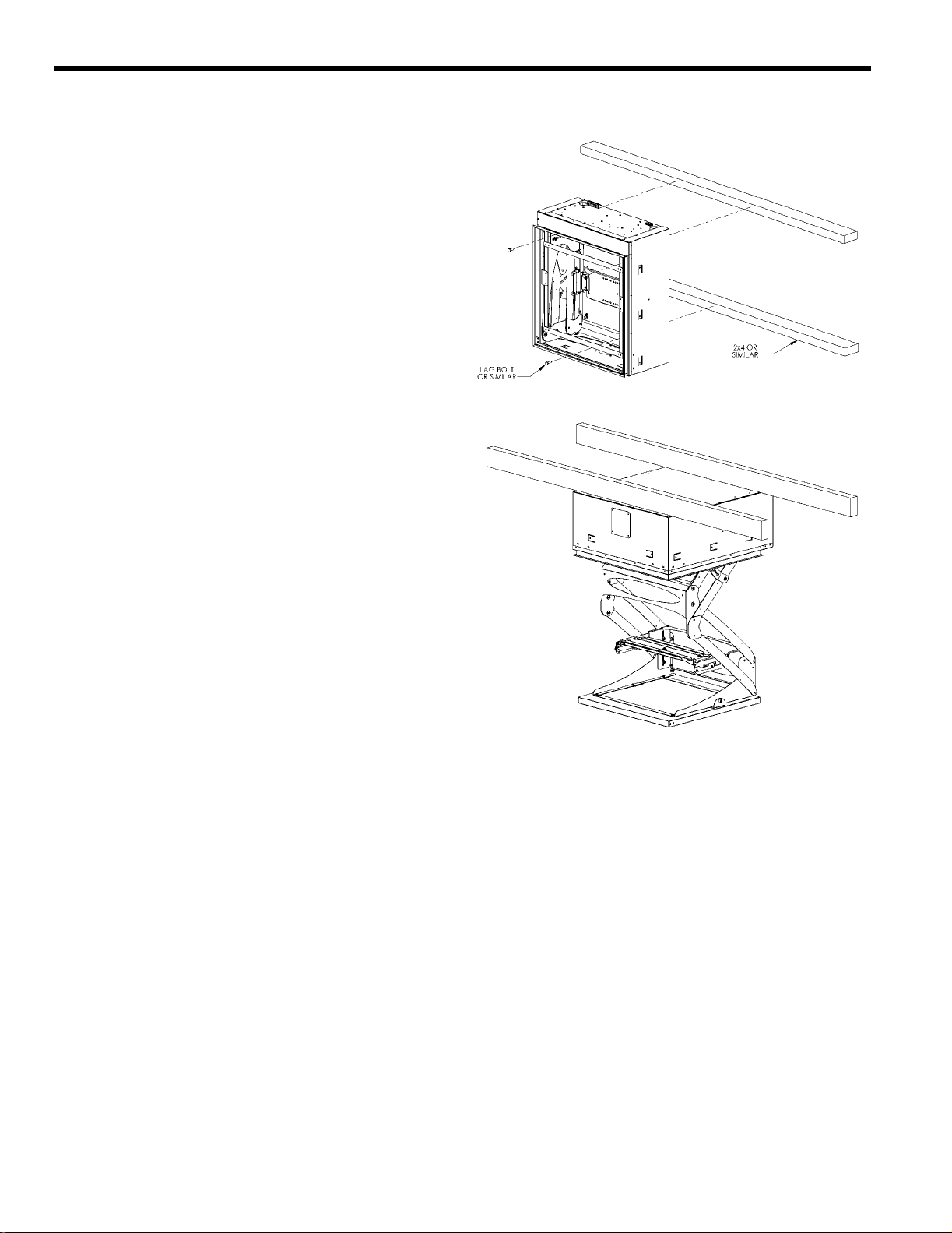
Installation in a Wood Framework (or Side-Mounted to Joists)
A suitable framework must be constructed to support the lift in the
ceiling. Refer to for dimensions of the lift. The lift housing has
mounting tabs to assist in side-mounting the lift to the ceiling joists
or otherwise securing it to a wood framework.
The idea l lift installation time is after the sheetrock has been
installed, but before the sheetrock has been mudded or finished.
1. Remove the closure panel from the bottom of the lift to gain
access to the front a nd back mounting holes.
CAUTION: For smooth and reliable operat ion, the lift must be
installed square and parallel in all dimensions. Avoid stre ssing
the lift at any time during installation.
2. Position the lift in the desired locati on, making sure the unit is
level, squa re, parallel and the re is no stress applied to the box
(chassis).
3. Secure the lift to the joists or wood framework. Drive at least
six 1/4 x1-1/4-in. lag screws through the mounting tabs around
the inside of th e lift housing and mounting holes across the
back of the li ft. The re are 8 tab loc at ions, thr ee in each side and
two in one end, and 3 mounting hole locations across the back
of the lift (see Figure 6 and Figure 7). The lift requires support
on two opposing sides only.
4. After installing the lift, use the test push button to carefully
operat e the lift all the way up and down to b e sure the cl earances are adequa te . Be prepared to stop the li ft immedia tely
if the lift begi ns to sound l abor ed or if on e sid e or the oth er sid e
begins to travel slower.
5. To maintain plenum rating, seal any openings in the lift hous-
ing (except joist tabs) using foil tape.
The bottom of the lift may be painted or textured as necessary to
match the ceiling.
Figure 6. Mounting Locations
1/4 Dia. Lag Screw
ift Housing
Alternate 1/4 Dia.
Bolt Thru
Joist
Sheetrock
finish compound to hide
lift housing seam.
Bead Flange
Figure 7. Mounting Method
Finish C ei lin g
Compound
9
Page 11

Instruction Manual SMART-LIFT 236 Electric Ceiling Lifts
s
CONNECT POWER TO THE LIFT
WARNING: Plenum rating requires hard wiring and use of
Class II control wiring. Follow all loc al building and el ectrical
codes.
NOTE: If the lift is cycled up and down repeatedly, the thermal
overload on the motor may s top operation. Operation will
resume when the therma l overload cools and resets (5 to 15
minutes).
Non Plenum Rated Installation
1. Plug the lift’s power cord (s upplied) into an electrical outlet.
Plenum Rated Installation
WARNING: A licensed elec t rician should
disconnect and terminate the leads to the
power cord receptacle and, using the
access holes provided for a strain relief,
hard wire th e un i t to a pow e r so u rce .
WARNING: Failure to disconnect and terminate power leads
properly m ay result in equipment damage or personal injury.
1. Disconnect and termina te the electrical leads from the power
cord receptacle at the int erior junction box (see Figure 8).
2. Remove the electrical knockout and install the strain relief
(provided).
Terminate Power Lead
Electrical Junction Box
Inside Smartlift
Figure 8. Disconnect and Terminate
Power Cord Leads
3. Ha rd wire the unit to a 110V 60 Hz or 230V 50 Hz (as appropriate) 15-a mp power source.
4. Replace interior outlet in a horizontal position as noted on the
stickers found on th e outlet cover plate.
10
Page 12

(Optional) Installing Wiring Cover
An optional wiring cover may be installed to further protect
wiring from mechanical damage.
WARNING: Make sure that power to SL-236 is OFF before
proceeding!
1. Remove the control harness. (See Figure 9)
2. Using four Phillips head screws, attach cover (included in
kit) over hole created in Step 1.
3. Make control connections directly to the control box. (See
Inside Terminal Wiring Examples sections.)
4. Remove and save two Phillips head screws from opposite
corners of cover plate, and remove cover plate from
SL-236. (See Figure 9)
5. Place switch hole cover behind the cover plate and attach
with two Phillips head screws from the kit.
6. Replace cover plate and attach using two Phillips head
screws removed in Step 4.
7. Remove three Phillips head screws from SL-236.
8. Place motor wiring cover in place and attach with three
Phillips head screws removed in Step 7.
9. Remove three Phillips head screws from SL-236.
10. Place control wiring cover in place and attach with three
Phillips head screws removed in Step 9.
NOTE: Some components not shown for clarity.)
Cover
Plate
5
x 2
Switch Hole
Cover
Motor Wiring
Cover
7
4
x 2
x 3
8
6
x 2
Control Wiring
Cover
10
x 4
Control
Harness
2
1
9
x 3
x 3
Figure 9
11
Page 13

Instruction Manual SMART-LIFT 236 Electric Ceiling Lifts
INSTALL THE PROJECTOR ON THE LIFT
CAUTION: Improper proje ctor weight distribution could lead to
equipment damage. Make certain projector wei ght is centered
on cradle when mounted.
1. Install the SLB bracket on the projector (se e the SLB manual
for details).
2. Remove the yaw adjustment bracket from the lift (see
Figure 9).
3. Place the yaw adjustment bracket over the studs on the SLB as
shown, selecting the set of holes that best cent ers the weight of
the projector.
4. Install tapered thumb nuts (minimum 3), making sure the
tapered end is toward the projector.
5. Reinstall the yaw adjustment bracket with projector attached.
NOTE: If desired, the projecto r can be se t directly on the bottom
plate of the lift, not se cured by the bracke t. The bracket may be
removed for esthetic purpose by removing four roll/height
adjustment nuts (see ADJUSTMENTS).
Install and Route Cables
CAUTION: Do not attach cables to lower lifting arms or sides of
cradle. This may result in damage when lift retracts.
NOTE: Two routing paths are provid ed, one on ea ch side, to sepa-
rate electrical and video cables.
1. Lower lift to service position.
2. Route and secure all electrical and vide o cables using ties and
eyelets provided (see Figure 10), leaving some slack between
securing points .
3. Plug the projector’s power cord into one of the two outlets
inside the lift. One outlet is swi tched and the other is continuously li ve. The swi tched out let is mar ke d wi th an “S ”.
Figure 9. Install Projector
Figure 10. Cable Routing Example
12
Page 14

Instruction Manual SMART-LIFT 236 Electric Ceiling Lifts
ADJUSTMENTS
Adjust Travel
An access hole is located in the corner below the termina l block
(see Fig u re 11). Using a Ph illips screwdr iv er inserted in the access
hole, adjust the stroke of the lift mechanism as follows:
CAUTION: Do not over adjust (exceed maximum trav el) stroke
length.
1. Shorten stroke by tu rning the adjustment screw clockwise one
or two turns, check for the desired stroke length, and repeat as
necessary.
2. Lengthen stroke by turning the adjustment screw clockwise
one or two tu rns , check for the de sire d stro ke le ngth, a nd repeat
as necess ar y.
Adjust the Aim of the Projector
Center the lens (see Fi gure 12). The aim of the projector can be
adjusted in all directions, as shown:
1. Lower the lif t to the 'show' position.
2. Pitch and forward/Aft. There are four 10-24 Nylock nuts
(two on each side) on the outs ide of the carriage. L oos en these
nuts slightly, tip the carriage in the slotted holes to the desired
angle, and tighten the nuts. For forward and aft adjustment,
loosen the four pitch adjustment nuts. Lift sl ightly, moving forward or aft until tray falls into desired notch and tighten the
nuts.
CAUTION: Each side must be ad justed equall y. Failure to adjust
each side equally m ay re sult in equipment and lift damage
when the lift closes .
3. Roll/Height. There are four 1/4-20 n u ts at the rear in side cor -
ners of the cradle assembly. Slightly loosen these nuts, gently
raise or lower the cradle to the desir ed posit ion, and tighte n the
nuts.
4. Yaw. There are four 10-24 Nylock nuts (two on each side) on
the top of the carriage. Loosen these screws slightly, turn th e
carriage in the slotted holes to the desired angle, and tighten
the nuts.
Figure 11. Travel Adjustment
13
Figure 12. Projector Adjustment
Page 15

Instruction Manual SMART-LIFT 236 Electric Ceiling Lifts
OUTSIDE TERMINAL WIRING EXAMPLES
The information on the following pages cover the most common wiring options:
• Supplied Momentary Push Button
• Discrete Extend and Retract for switch or dry contacts
• 12 Volt out supply
• 24 Volt out supply
• Two dry contact closures
• Service Extend
CAUTION: Closing the unit while the projector is running may
cause premature bulb failure and may damage both the lift and projector.
Push Button
Supplied Single Pole Single Throw (SPST) Switch
Using Internal 24VA C Power Supp ly
a. Connect the green jumper wire (supplied) to terminals 1 & 5
(see Figure 13).
b. Connect the SPST switch (supplied) to terminals 2 & 6.
Supplied SPST Switch Using Internal 12VDC Power Supply
a. Connect the green jumper wire (supplied) to terminals 5 & 9
(see Figure 14).
b. Connect the SPST switch (supplied) to terminals 6 & 10.
Supplied SPST Switch Using External Power Supply
a. Connect the negative of your power supply to terminal 5 (see
Figure 15).
b. Connect the SPST swi tch (supplied) to terminal 6 & the pos-
itive of your power supply .
Figure 13. 24VAC Internal
Figure 14. 12DC Internal
Figure 15. External Power Supply
14
Page 16

Instruction Manual SMART-LIFT 236 Electric Ceiling Lifts
Single Pole Double Throw (SPDT) Switch or
2 Dry Contact Closures, Momentary or Latching.
These terminals can be use d with any latc hing cont acts , momen tar y
contacts, or a wall switch.
NOTE: The connection be tween the ground (#9) and any other te r-
minal connectio n must be broke n (open) be fore comple ti ng the
next circuit..
a. Connect the common wire from your switch to
terminal 9 (see Figure 16).
b. Connect the 'up' wire from your switch to terminal 3.
c. Connect the 'down' wire from your switch to terminal 4.
Internal 12VDC Power Supply 2.5A Maximum
(+) = Terminal 10
(-) = Terminal 9
NOTE: Non regulated, open ci rcuit voltage may exceed 18V.
Internal 24VAC power supply, 1.2 A max
(+) = Terminal 1
(-) = Termina l 2
Internal dry contact closures:
Common = Terminal 12
Closed when lift reac hes show position = 14
Closed when lift is fully closed = 13
Service Position
Momentary contact between term inals 9 & 11 will lower the
lift to the service position.
NOTE: To stop the lift before it reaches the service position, make
a momentary contact be twee n terminals 3 & 9.
.
Figure 16. Dry Contacts
15
Page 17

Instruction Manual SMART-LIFT 236 Electric Ceiling Lifts
INSIDE TERMINAL WIRING EXAMPLES
The information on the following pages cover the most common wiring options:
• Supplied Momentary Push Button
• Discrete Extend and Retract for Switch or Dry Contacts
• 12 Volt out supply
• 24 Volt out supply
• Two dry contact closures
• Vol tage Sensing
• Service Extend
CAUTION: Closing the unit while the projector is running may
cause premature bulb failure and may damage both the lift and projector.
Push Button
Supplied Single Pole Single Throw (SPST) Switch Using
Internal 24VAC Power Supply
a. Connect the green jumper wire (supplied) to terminals 2 & 6
(see Figure 17).
b. Connect the SPST switch (supplied) to terminals 1 & 5.
Supplied SPST Switch Using Internal 12VDC Power Supply
a. Connect the green jumper wire (supplied) to terminals 6 &
10 (see Figure 18).
b. Connect the SPST switch (supplied) to terminals 4 & 5.
Supplied SPST Switch Using External Power Supply.
a. Connect the negative of your power supply to terminal 6 (see
Figure 19).
b. Connect the SPST switch (supplied) to terminal 5 & the pos-
itive of your power supply.
Figure 17. 24VAC Internal
Figure 18. 12DC Internal
Figure 19. External Power Supply
16
Page 18

Instruction Manual SMART-LIFT 236 Electric Ceiling Lifts
Single Pole DOUBLE Throw (SPDT) Switch or
2 Dry Contact Closures, Moment ary or Latching.
a. Connect the common wire from your switch to
terminal 13 (see Figure 20).
b. Connect the 'up' wire from your switch to terminal 12.
c. Connect the 'down' wire from your switch to
terminal 11.
Internal 12VDC Power Supply 2.5A Maximum
(+) = Te rminal 4
(-) = Terminal 3
NOTE: Non regula ted, open circuit voltage may exceed 18V.
Internal 24VAC Power Supply, 1.2A Maximum
(+) = Te rminal 1
(-) = Terminal 2
Internal Dry Contact Closures:
Common = Terminal 12
Closed when lif t reaches show position = Terminals 16 and 17
Closed when lift is fully closed = Terminals 18 and 19
Low Voltage Sensing:
a. Connect the positive of your power supply to terminal 7.
b. Connect the negative of your power supply to termina l 8.
NOTE: The lift will complete a full cycle even if the supply is
turned off before the lift reaches full extension.
NOTE: When the lift is in the lowered position using this option,
the li ft wi ll ig nor e al l other com mands u nti l i t has c omple ted i ts
full cy cle.
When the power supply is on, the lift will extend. When the
power supply turns off, the lift will retract.
Figure 20. Dry Contacts
Service position:
Momentary contac t between terminals 9 & 10 will lower the
lift to th e s ervice po s i ti o n.
NOTE: To stop the lift before it reaches the service pos ition, make
a momentary contact between terminals 11 & 13.
17
Page 19

Instruction Manual SMART-LIFT 236 Electric Ceiling Lifts
SMART LIFT INTERIOR BOARD BOX
TERMINAL FUNCTION DEFINITIONS
TERMINAL
NUMBER
1
2
3
4
5
6
FUNCTION
24 VOLT AC 24 volt AC output
24 VO LT AC
COMMON
GROUND Ground
12 VOLT DC 12 volt DC
EXTEND/
RETRACT
EXTEND/
RETRACT
COMMON
DESCRIPTION WIRING OPTIONS NOTES
24 volt AC common
Initiates movement if lift is static, or
stops movement if lift is in motion.
Direction of travel will be opposite
of last direction of travel.
Used in conj unction with
Extend / Retr act when using an
external power source to initiate
movement.
To Operate using Internal Power
Source
Connect terminals 3 & 6 with
Jumper Wire. Connect
Momentary Switch to terminal 4.
Connect other line of Mome ntary
Switc h to terminal 5.
To Operate using External Power
Source
Connect External Power Supply’s
Common to terminal 6. Connect
initiating signal to terminal 5.
This is an internal power supply for
powering external devices & Remote
Controllers.
Chief Mfg. offers the RC-10 Radio
Frequency Remote Controller which runs
off of this power supply.
This is an internal power supply for
powering external devices &/or used for
initiating specific functions
(
Extend/Retract 5 or Voltage Sensor 7).
Function operates on momentary switch
only.
Operating range is 5 – 30 Volts AC or DC.
NOT TO BE USED AS GROUND FOR
FUNCTION OTHER THAN
EXTEND/RETRACT TERMINAL 5.
7
8
9
10
When terminal sen ses volt a ge, uni t
VOLTAGE
SENSOR
VOLTAGE
SENSOR
COMMON
SERVICE
EXTEND
GROUND Ground
When terminal senses cessation of
Used in conj unction with Voltage
Sensor when using an external
power source to initiate movement.
Extends unit to ma ximum li mit,
bypassing normal-use travel setting.
Often used for servicing projectors
will exte nd.
voltage, unit will retract.
in ceiling lifts.
Voltage Sensing
Connect positive lead to terminal
7. Connect Ground of switching
device to terminal 8.
Single-Pull/Throw Latching
Switch
Connect terminals 3 & 8 with
Jumper Wire. Connect fi rst
Switch Terminal to terminal 4.
Connect other Switch Terminal to
terminal 7.
Momentary or Latching contact to
Ground terminals 3, 10, 13, or 20.
Operating range is 5 – 30 Volts AC or DC.
NOT TO BE USED AS GROUND FOR
FUNCTION OTHER THAN VOLTAGE
SENSOR TERMINAL 7.
Feature not available on all models.
If using Latching Switch, be sure to
disengage Switch prior to initiating any
other fun ct i on.
18
Page 20

Instruction Manual SMART-LIFT 236 Electric Ceiling Lifts
11
12
13
14
15
16
17
18
19
20
EXTEND
RETRACT
GROUND
EXTEND
ERROR
RETRACT
ERROR
EXTEND
LIMIT
RELAY
EXTEND
LIMIT
RELAY
COMMON
RETRACT
LIMIT
RELAY
RETRACT
LIMIT
RELAY
COMMON
GROUND
Ext en d s un it to pr ese t tra ve l lim it.
Customer w ithin a preset maximum
range may adjust travel limits.
Re tr a c ts u n it to p r e s et tra v e l limit.
Tra v e l limits m a y be adju s te d b y
customer within a preset maximum
range.
Ground
Imm ediately reverses direction of
travel when triggered while unit is
extending.
Imm ediately reverses direction of
travel when triggered while unit is
retra c tin g .
Closes set of internal dry contacts
when unit reaches full extension.
Closes set of internal dry contacts
wh e n u nit reaches full retr action.
Ground
Momentary or Latching contact to
Ground terminals 3, 10, 13, or 20.
Momentary contact to Ground
terminals 3, 10, 13, or 20.
RATED FOR 1 AMP @ 24 VOLTS
If using Latching Switch, be sure to
disengage S witch pr io r to initiating a n y
other function.
If using Latching Switch, be sure to
disengage S witch pr io r to initiating a n y
other function.
Chief Mfg. offers the SS-10 Pressure
Sen s itiv e Safet y S t rip to p rovide t h is
function.
Please specify how many inches required
spanning entire pinch zone.
S-10 must be ordered with the ST-15
The S
Terminals.
1.0 AMP@30VDC
0.5 AMP@125VAC
0.3 AMP@60VDC
RATED FOR 1 AMP @ 24 VOLTS
1.0 AMP@30VDC
0.5 AMP@125VAC
0.3 AMP@60VDC
19
Page 21

Instruction Manual SMART-LIFT 236 Electric Ceiling Lifts
SMART LIFT EXTERIOR 14 PIN
TERMINAL FUNCTION DEFINITION
TERM INA L
NUMBER
1
2
3
4
5
6
7
8
FUNCTION
24 VOLT AC 24 volt AC output
24 VOLT AC
COMMON
RETRACT
EXTEND
EXTEND/
RETRACT
COMMON
EXTEND/
RETRACT
RETRACT
ERROR
EXTEND
ERROR
DESCRIPTION W IRING OPTIONS N OTES
24 volt AC comm on
Retracts unit to preset travel limit.
Travel limits may be adjusted by
customer within a preset maximum
range.
Ex te n ds u ni t to p res e t tr a v el limit.
Customer within a preset maximum
range may adjust travel limits.
Used in conjunction with
Extend/Retract when using an
external power source to initiate
movement.
Init ia te s m o v e m e n t if lift is s ta tic , o r
stops movement if lift is in motion.
Direction of travel will be opposite
of last direction of travel.
Immediately reverses direction of
travel when triggered while unit is
retracting.
Immediately reverses direction of
travel when triggered while unit is
extending.
Mom entary or Latching contact to
Ground terminals 9, or 11.
To Operate using Internal Power
Source
Connect terminals 9 & 5 with
Jumper W ire. Connect
Momentary Switch to ter minal
10. Connect other line of
Momentary Switch to ter minal 6.
To Operate using External Power
Source
Connect External Power Supply’s
Comm on to terminal 5. Connect
initia t in g s ig n al to te r minal 6.
Mom entary contact to Ground
terminals 9, or 11.
This is an internal pow er supply fo r
powering external devices & Remote
Controllers.
Chief Mfg. offers the RC-10 Radio
Frequency Remote Controller which runs
off of this power supply.
If using Latching Switch, be sure to
disengage Switch prior to initiating any
other function.
If using Latching Switch, be sure to
disengage Switch prior to initiating any
other function.
NOT TO BE USED AS GROUND FOR
FUNCTION OTHER THAN
EXTEND/RETRACT TERMINAL 5.
Function o pe rates on momentary s w itch
only.
Operating range is 5 – 30 Volts AC or DC.
Chief Mfg. offers the SS-10 Pressure
Sensitive Safety Strip to provide this
function.
Please specify how m any inches required
to span entire pinch zone.
The SS-10 must be ordered with the ST-15
Terminals.
9
10
11
GROUND Ground
12 VOLT DC 12 volt DC
Extends un it to maximum lim it,
bypassing normal-use travel setting
Service Extend
Often used for servicing projectors
in ceiling lifts.
Mom entary or Latching contacts
to Ground terminals 3, 10, 13, or
20
This is an internal pow er supply fo r
powering external devices &/or used for
initiating specific functions
Extend/Retract 6).
(
Feature not available on all models.
If using Latching Switch, be sure to
disengage Switch prior to initiating any
other function
20
Page 22

Instruction Manual SMART- LIFT 236 Electric Ceiling Lifts
LIMIT
12
RELAY
COMMON
13
14
RETRACT
LIMIT
RELAY
EXTEND
LIMIT
RELAY
Closes set of internal dry contacts
when unit reaches full retraction.
Closes set of internal dry contacts
when unit reaches full extension.
RATED FOR 1 AMP @ 24 VOLTS
1.0 AMP@30VDC
0.5 AMP@125VAC
0.3 AMP@60VDC
21
Page 23

Instruction Manual SMART-LIFT 236 Electric Ceiling Lifts
TROUBLESHOOTING
SYMPTOM POSSIBLE CAUSE CORRECTIVE ACTION
LIFT DOES NOT RESPOND 12V TRIGGER OPTION BEING USED NORMAL OPERATION
NO POWE R VERIFY POWER TO LIFT
FUSE BLOWN CHECK FUSE ON CONTROL BOX
IMIT SWITCH CALL CHIEF FOR VERIFICATION
L
LIFT WILL NOT LOWER/RAISE
CONTROL BOX CLICKS
MOTOR SILENT
LIFT WILL NOT LOWER/RAISE
CONTROL BOX CLICKS
MOTOR HUMS
PROJECTOR CRADLE / BOTTOM
PANEL LOWER ON ONE SIDE.
FAILED CONTROL BOX CALL CHIEF FOR VERIFICATION
OVERHEATED MOTOR LET MOTOR COOL FOR 5-15 MINUTES.
FAILED MOTOR CALL CHIEF FOR VERIFICATION
BINDING MECHANISM MAKE SUR E CABLES ARE ROUTED PROPERLY
FAILED MOTOR CALL CHIEF FOR VERIFICATION
FAILED CONTROL BOX CALL CHIEF FOR VERIFICATION
NORMAL OPERATION A DIFFERENCE OF UP TO 3/16" WITHIN THE FINAL 4" OF
LIFTING LINKS OUT OF ADJUSTMENT CALL CHIEF
SEE NOTES ON 'LOW VOLTAGE SENSING' PAGE#16
SEE 'INSTALL AND ROUTE CABLES' PAGE#11
TRAVEL IS NORMAL
WHEN THE LIFT IS EXTENDED BEYOND 4", UP TO 3/8"
DIFFERENCE IS NORMAL
PROJECTOR CRADLE / BOTTOM
PANEL SIGNIFICANTLY LOWER ON
ONE SIDE
HOOKS ON LIFTING BRACKET DO
NOT CATCH THE ROLLERS ON THE
PROJECTOR CRADLE.
LIFTING BRACKET DAMAGED CALL CHIEF
DAMAGED HINGE ASSEMBLY CALL CHIEF
LIFTING BRACKET DAMAGED CALL CHIEF
BINDING MECHANISM MAKE SUR E CABLES ARE ROUTED PROPERLY
SEE 'INSTALL AND ROUTE CABLES' PAGE#11
LIFTING LINKS OUT OF ADJUSTMENT CALL CHIEF
LIFTING BRACKET DAMAGED CALL CHIEF
DAMAGED HINGE ASSEMBLY CALL CHIEF
22
Page 24

Instruction Manual SMART-LIFT 236 Electric Ceiling Lifts
PAGE LEFT BLANK INTENTIONALLY
23
 Loading...