

Page 1
INSTALLATION INSTRUCTIONS
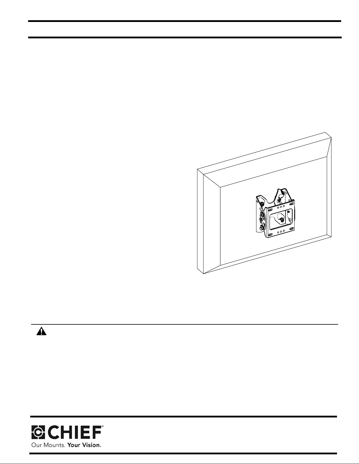
SMALL FLAT PANEL ADJUSTABLE PITCH
WALL MOUNT
Model: FTR Series
Specifications:
• Designed for installation on single wood studs or
drywall (1/2" minimum thickness); either option
provides ±1/2" lateral shift.
• Weight capacity:
• 45 lbs (20 kg) for wood stud installation
• 30 lbs (14 kg) for drywall installation
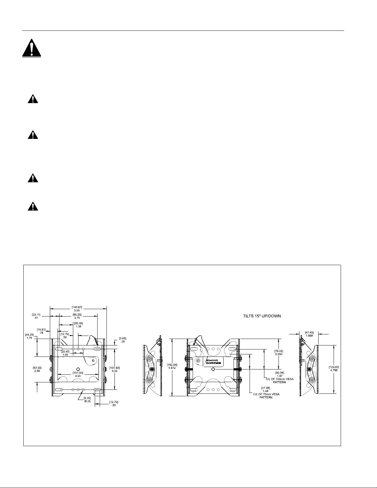
• Provides tilt range from 5° up to 15° down.
BEFORE YOU BEGIN
WARNING: It is the installer’s responsibility to make sure all component s are properly assembled and inst alled using
the instructions provided. Failure to read, thoroughly understand, and follow all instructions can result in serious
personal injury, damage to equipment, or voiding of factory warranty.
• If you have any questions about this these inst ructions or your spe cific installation, contact Chief Ma nufacturing
at 1-800-582-6480 or 952-894-6280.
Chief® is a trademark of Milestone AV Technologies, Inc. All rights reserved.
Chief Manufacturing, a division of Milestone AV Technologies
1-800-582-6480 952-894-6280 Fax: 952-894-6918
8401 Eagle Creek Parkway, Ste 700
Savage, Minnesota 55378 USA
©2008 Milestone AV Technologies
8804-000343 RevA
www.chiefmfg.com
06/08
Page 2
Model: FTR Series Installation Instructions
Measurements in: [millimeters]
inches
IMPORTANT WARNINGS AND CAUTIONS!
WARNING: A WARNING alerts you to the possibility of serious injury or death if you do not follow the instructions.
CAUTION: A CAUTION alerts you to the possibility of damage or destruction of equipment if you do not follow the
corresponding instructions.
WARNING: It is the installer’s responsibility to make sure the structure to which this unit is attached can support five
times the combined weight of all equipment. Reinforce the structure as required before installing the unit. Failure to
provide adequate structural strength for this unit can result in serious personal injury or damage to equipment!
WARNING: It is the installer’s responsibility to make sure the combined weight of the display, mount, accessories,
and any other attached equipment must not exceed 45 lbs (20 kg) for wood stud installation OR 30 lbs (14 kg) for
drywall installation, the maximum support weight of this unit. Exceeding the maximum support weight can result in
serious personal injury or damage to equipment!
WARNING: Make sure the latches securing the display are fully closed at all times except when removing or
installing the display. The latches must be fully closed when installing or removing cables from the display.
WARNING: Watch for pinch points. Do not put your fingers between movable parts.
DIMENSIONS
2
Page 3
Installation Instructions Model: FTR Series
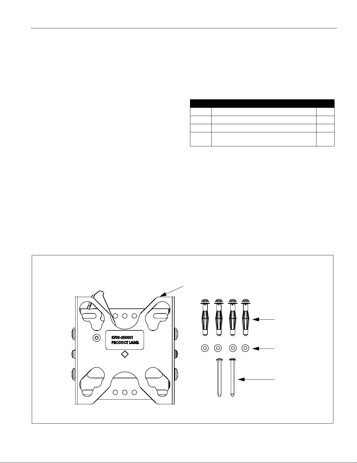
Table 1: Parts
Item Description Qty
10 PLATE, Wall 2
20 ANCHOR, Hollow Wall, #10-24 4
30 WASHER, Flat, Standard Machine Screw, #10 4
40 SCREW, Phillips Pan Head Sheet Metal,
#10 x 2-1/2"
2
(20)
(30)
(10)
(40)
TOOLS REQUIRED FOR INSTALLATION
• Drill
• 1/8" drill bit (wood stud installation)
• 3/8" drill bit (drywall installation)
• Hammer (drywall installation)
• Phillips screwdriver, #2
NOTE: Other tools may be required de pe ndin g on you r
method of installation.
PARTS
After unpacking carton, inspect and verify contents (See
Figure 1). If any listed parts are missing or damaged,
contact Chief Customer Service at 1-800-582-6480.
Figure 1: Parts
3
Page 4

Model: FTR Series Installation Instructions
(30)
(40)
Wood
Stud
(2 places)
(2 places)
(10)
Pilot
(2 places)
Holes
Drywall
Not collapsed
Collapsed
Anchor barb
INSTALLATION
The FTR may be installed on either a single wood stud,
or drywall (1/2" minimum thickness).
INSTALL MOUNT TO SINGLE WOOD STUD
1. Determine approximate mounting location, ke eping in
mind the display size.
2. Use a stud sensor to locate applicable wood stud.
Mark location with a pencil.
3. Level plate (10) at desired height and, using plate (10)
as a template, mark the location of upper and lower
pilot holes. Ensure marks are in the center of wood
stud.
NOTE: Mount can provide ±1/2" of lateral shift by using
mount holes on either side of vertical centerline.
WARNING: ELECTRICAL SHOCK HAZARD! Drilling
into electrical wires or cables can cause DEATH or
SERIOUS PERSONAL INJURY! ALWAYS make
certain area behind mounting surfaces is free of
electrical wires and cables before drilling or installing
mount fasteners.
4. Drill pilot holes using a 1/8" drill bit. Ensu re pilot holes
are straight.
INSTALL MOUNT TO DRYWALL
WARNING: Drywall must be 1/2" minimum thickness.
Failure to provide adequate structural strength for this
unit can result in serious personal injury or damage to
equipment!
1. Determine approximate mounting location, ke eping in
mind the display size.
2. Level plate (10) at desired height an d, using plate (10)
as a template, mark the location of the four anchor
holes (one in each corner slot).
WARNING: ELECTRICAL SHOCK HAZARD! Drilling
into electrical wires or cables can cause DEATH or
SERIOUS PERSONAL INJURY! ALWAYS make
certain area behind mounting surfaces is free of
electrical wires and cables before drilling or installing
mount fasteners.
3. Drill anchor holes using a 3/8" drill bit. Ensure holes
are straight and completely through drywall.
4. Insert anchor (20) into anchor hole and seat with
gentle tapping from hammer . Anchor barbs should be
fully engaged in drywall (See Figure 3).
5. Using Phillips screwdriver, insert screw (40) through
washer (30), plate (10), and drywall (not shown) and
install into pilot holes (See Figure 2).
Figure 2: Installation to Single Wood Stud
6. Repeat for remaining screw (40).
7. Tighten both screws (40) securely.
Figure 3: Drywall Anchor
5. Using Phillips screwdriver, tighten anchor screw until
anchor has fully collapsed against back side of
drywall.
NOTE: Anchor screw will feel tight until anchor begins to
collapse. Screw will then turn easier for many
turns. Screw will feel tight when anchor has fully
collapsed.
6. Repeat steps 4. and 5. for remaining anchors.
7. Remove and retain anchor screws from anchors (20).
NOTE: Anchors (20) may come with small washers which
may be left on the screw or discarded. These
small washers do NOT replace washers (30).
4
8. Using Phillips screwdriver, insert anchor screws
through washers (30) and plate (10) and install into
Page 5

Installation Instructions Model: FTR Series
(20)
(4 places)
(30)
(4 places)
Anchor
(4 places)
(10)
Screw
(10)
Latching
Flag
NOTE: Display not shown for clarity.
Button location for
100mm x 100mm
pattern (4 places)
Button location for
75mm x 75mm
pattern (4 places)
NOTE: Display not shown for clarity.
(10)
Latching
Flag
collapsed anchors (20). Tighten until secure (See
Figure 4).
Figure 6: Install Display to Plate
Figure 4: Installation to Drywall
INSTALL DISPLAY TO MOUNT
NOTE: Proper interface must be attached t o display. See
instructions that come with interface assembly.
1. Open latching flag by rotating flag clockwise on pla te
(10) (See Figure 5).
3. Close latching flag by rotating flag counterclockwise
on plate (10) (See Figure 7).
NOTE: An optional padlock may be used to secure
latching flag.
Figure 7: Close Latching Flag
Figure 5: Open Latching Flag
2. Lift and maneuver display such that all buttons fit into
button openings on plate (10). Lower displa y firmly
into place. Ensure each button h as fully seated in it s
button opening (See Figure 6).
NOTE: Mounting buttons are shown in the 100mm x
100mm pattern. Plate (10) will also
accommodate a 75mm x 75mm pattern.
4. Connect cables to display as required.
REMOVE DISPLAY FROM MOUNT
1. Disconnect all cables from display.
2. Open latching flag by rota ting fl ag clockwise on plate
(10) (See Figure 5).
3. Lift and maneuver display mounting buttons out of
button openings.
5
Page 6

Model: FTR Series Installation Instructions
5° Tilt Up
15° Tilt Down
Adjusting
Screw
(other side
similar)
ADJUST TILT
1. Loosen adjusting screws on each side of display (See
Figure 8).
2. Adjust tilt as desired.
3. Retighten adjusting screws.
Figure 8: Tilt Adjustment
6
Page 7

Installation Instructions Model: FTR Series
7
Page 8

Model: FTR Series Installation Instructions
8
 Loading...