

Page 1
FSD-4100
INSTALLATION INSTRUCTIONS
LCD Flat Screen
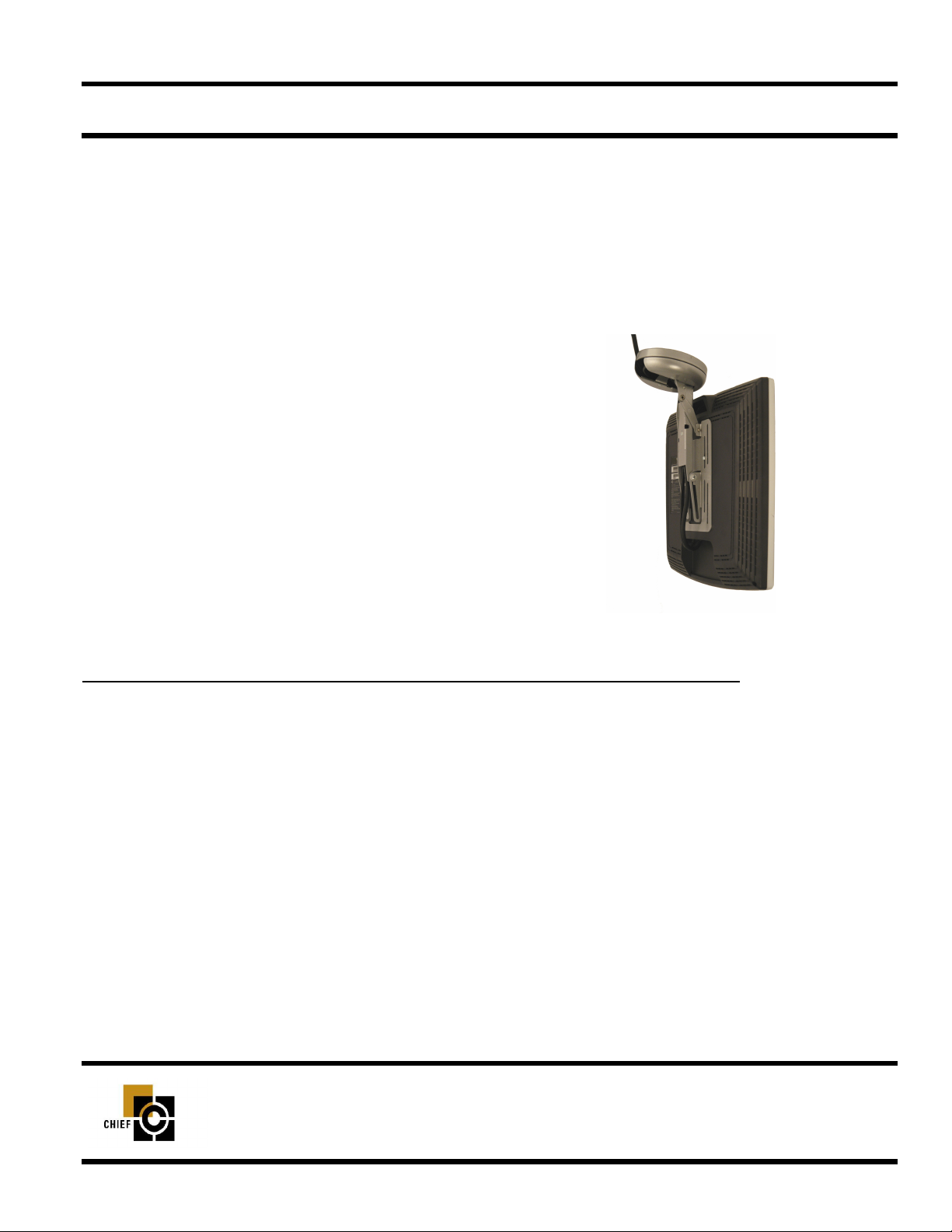
Swing-Down Mount
Perfect for home applications u nder kitchen cabinets or other
rooms with a soffit. The LCD Flat Screen Swing-Down mount is
a sturdy, versatile solution for LCD flat screen display or touch
screen control system mounting with 15” or smaller monitors.
The all steel mount provides smooth side-to-side pivot, 70º or
220º screen rotation and extends and retracts 2 3/4” to allow for
larger screen capacity. Hidden cable management permits aesthetic installation while preventing wires from being pinched.
BEFORE YOU BEGIN
• Caution: To prevent damage to the mount, which could affect the equipment that will be attached to it and
void the factory warranty, thoroughly study all instructions and illustrations before you begin the installation. Pay particular attention to the “Important Warnings and Precautions” on Page 1.
• The mount is designed to be installed on cabinetry or supporting framework. The cabinet to which the FSD-4100 is
anchored must be capable of supporting 75 pounds (34 Kg).
• If you have any questions about this installation, contact Chief Manufacturing at 1-800-582-6480.
CHIEF MANUFACTURING INC.
1-800-582-6480 952-894-6280 FAX 952-894-6918
8401 EAGLE CREEK PARKWAY
SAVAGE, MINNESOTA 55378 USA
8832-000010 Rev C
©2007 Chief Manufacturing
www.chiefmfg.com
04-07
Page 2

Installation Instructions FSD-4100
IMPORTANT WARNINGS AND PRECAUTIONS!
WARNING: A WARNING alerts you to the possibility of serious injury or death if you do not follow the instructions.
CAUTION: A CAUTION alerts you to the possibility of damage or destruction of equipment if you do not follow the corre-
sponding instructions.
• WARNING:Improper installation can result in serious personal injury! Make sure that the mounting surface can sup-
port a redundant weight factor five times the total weight of the equipment. If not, reinforce the structure
before installing the FSD-4100.
• WARNING:Be aware also of the potential for personal injury or damage to the unit if it is not adequately mounted.
• WARNING:The installer is responsible for verifying that the surface to which the FSD-4100 is anchored will safely
support the combined load of all attached components or other equipment.
• WARNING:The weight of the display placed on the FSD-4100 must not exceed 15 lbs. (6.8 kg), the maximum load
capacity of the FSD-4100.
• WARNING:Watch for pinch points. Do not put your fingers between movable parts.
• WARNING:Make sur e the mount and brackets are correctly oriented.
• CAUTION: Check the unit for shipping damage before you begin the installation.
• CAUTION: Overtightening adjustment bolt will cause excessive wear and may distort adjustment components.
NOTE: Hardware for attaching this unit to the mounting surface is not supplied.
TOOLS REQUIRED FOR INSTA LLATION
• Phillips screw driver
• Electric drill motor
• 1/4” Drill bit
NOTE: Other tools may be required depending on the
method of installing the mount.
CONTENTS
DIMENSIONAL DRAWING ........................................ 2
INSPECT THE UNIT BEFORE INSTALLING ............ 3
PARTS ....................................................................... 4
FDS-4100 INSTALLATION ........................................ 5
MOUNT THE DISPLAY ............................................. 5
ADJUSTMENTS ......................................................... 6
CABLE MANAGEMENT ............................................. 7
1
Page 3
Installation Instructions FSD-4100
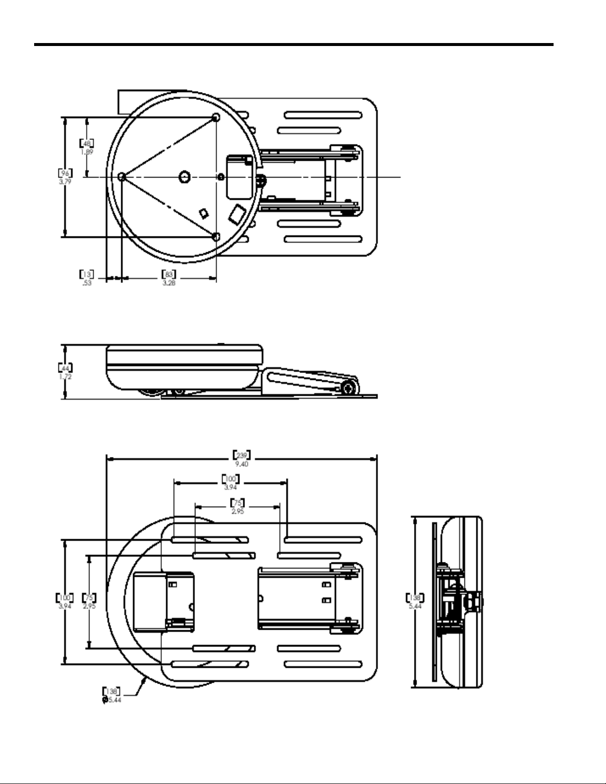
DIMENSIONAL DRAWING
2
Page 4

Installation Instructions FSD-4100
INSPECT THE UNIT BEFORE INSTALLING
WARNING: Watch for pinch points. Do not put your fingers
between movable parts.
1. Carefully inspect the FSD-4100 for shipping damage. If any
damage is apparent, call your carrier claims agent and do not
continue with the installation until the carrier has reviewed the
damage.
NOTE: Read all instructions before starting installation.
2. Lay out components to ensure you have all the required parts
before proceeding (see “DIMENSIONAL DRAWING” on
page 2 and “PAR TS” on pag e 4).
3
Page 5

Installation Instructions FSD-4100
PARTS
Item Description Qty. Item Description Qty.
10 Mount 1 40 Screw, M4 X .7 X 20mm 4
10A Base Cover 1 50 Screw, M4 X .7 X 10mm 4
10B Cable Management Cover 1 60 Spacer, Nylon, .500 OD X .19 X .50 4
20 Nuts, T 3 70 Tie Wraps 4
30 Screws, 10-24 X 5/8” 3 80 Allen Wrench, 5/32” 1
10
10A
10B
20
30
40
50
70
60
80
4
Page 6

Installation Instructions FSD-4100
FSD-4100 INSTALLATION
WARNING: It is the responsibility of the installer to verify that
the surface to which the FSD-4100 is anchored will
safety support the combined load of all attached
components and equipment .
Install the FSD-4100 as follows:
NOTE: Numbers in ( ) refer to parts in PARTS on page 4.
1. Remove two screws securing base cover (10A) and remove
cover (see Figure 1).
2. Determine the exact mounting location prior to installation,
considering the unit’s total arm radius.
3. Using the mounting plate as a template, mark mounting hole
locations (see Figure 2).
Base
Cover
Screws
4. Drill three 1/4” holes at the locations marked in step 3.
WARNING: Improper installation can result in serious dam-
age to the display or personal injury! Make sure
that the structural mem bers can support a redundant weight factorfive times the total weight of the
equipment. If not, reinforce the structure before
installing the FSD-4100.
5. Wit h the FSD -4100 c orrectl y oriente d and leve l, secure i t to the
surface using fasteners (20 and 30).
6. Check mount to insure it is level and adjust to level if necessary.
MOUNT THE DISPLAY
1. Make sure no power is supplied to the display before attempting to mount the display.
WARNING: Watch for pinch points. Do not put your fingers or
cables between movab le parts.
2. Align the appropriate slots in the bracket with the four mounting holes of your LCD display (see Figure 3).
Figure 1. Remove Cover
Mark
Hole
Locations
Figure 2. Mark Mounting Location
WARNING: Make sure the mounting screws used to s ecure
your display panel to the mounting bracket are the
proper length and diameter. If you are unsure
about screw length and/or diameter, consult the
display manufacturer before proceeding.
3. Using the proper length and diameter screws (40 or 50), and
spacers (60) as necessary, secure your display to the mount.
NOTE: If your display is not equippedwith 75 \mm or 100mm
mounting pa ttern, contact Chief Manufacturing to check for an
adapter plate for your display model.
Secure
Display
Figure 3. Secure Display
5
Page 7

Installation Instructions FSD-4100
ADJUSTMENTS
Screen Height Adjustment
1. Using a screw driver, slightly loosen the screws (40
or 50) securing the display panel to the mounting bracket
(see Figure 4).
2. Adjust the display panel to the desired hei ght.
3. Using a screw driver, tighten the screws securing the display panel to the mounting bracket.
Arm Tension Adjustment
CAUTION: Overtightening adjustm ent bolt will cause excessive wear and may distort adjustment components.
1. Using a 5/32” Allen wrench (80), slightly tighten or loosen
the tension adjustment bolt at the base of the arm (see
Figure 5) .
2. With display mounted, cycle the FSD to check for desired
tension.
3. Repeat Step 1 and Step 2 until desired tension is
obtained.
Screws
Securing
Monitor
Figure 4. Loosen/Tighten Screws
Securing Monitor
Tension Adjustment Bolt
Figure 5. Adjust Arm Tension
6
Page 8

Installation Instructions FSD-4100
CABLE MANAGEMENT
1. Remove screw and cable management cover (10B) (see
Figure 6).
2. Route the power/audio/video cables down the arm (see
Figure 7).
3. Route the power/audio/video cables through the slot in the bot-
tom of the arm (see Figure 8).
4. Secure the power/audio/video cables using tie wraps.
5. Proceed to “Right and Left 35 Degree Rotation” on page 8 or
“Right and Left 110 Degree Rotation” on page 9, depending
upon your application.
Figure 6. Cable Management Cover
Cable
Management
Cover
Figure 7. Route Cables Down Arm
Tie Wraps
Figure 8. Route & Tie Wrap Cables (Arm)
7
Page 9

Installation Instructions FSD-4100
Right and Left 35 Degree Rotation
1. Turn the base 35 degrees in one direction to its stop (see
Figure 9).
2. Neatly and carefully, route the power/audio/video cables
through the slot in the side of the base.
3. Secure the power/audio/video cables using a tie wrap (70).
4. Trim excess from tie wrap.
5. Install cable cover (10B) on arm and secure using screw (see
Figure 10).
6. Install base cover (10A) on base and secure using two screws
(see Figure 10).
35 Degrees
Stop
Tie Wrap
Slot
Figure 9. Route & Tie Wrap Cables (Base)
Cable Cover
Base Cover
Figure 10. Install Base and Cable Covers
8
Page 10

Installation Instructions FSD-4100
Right and Left 110 Degree Rotation
1. Using an Allen wrench (provided), remove the 35 degree stop
(see Figure 11).
2. Turn the base 110 degrees in one direction to its stop (see
Figure 12).
3. Neatly and carefully, wrap power/audio/video cables twice
inside base with no slop or slack in cables (see Figure 13).
4. Route power/audio/video cables out access hole in base.
5. Secure cables to base using a tie wrap (70).
6. Trim excess from tie wrap.
7. Install cable cover (10B) on arm and secure using screw (see
Figure 10).
35 Degree Stop
8. Install base cover (10A) on base and secure using two screws
(see Figure 10).
Figure 11. Remove 35 Degree Stop
110 Degrees
Figure 12. Rotate 110 Degrees
Figure 13. Wrap Cables In Base
9
Page 11

Installation Instructions FSD-4100
Check Rotation
1. Rotate screen in one direction until it reaches its stop (see Figure 14).
2. If there is any binding or pinching, correct problem.
3. Rotate screen in the opposite direction until it reaches its stop
(see Figure 15).
4. If there is any binding or pinching, correct problem.
5. If your cables do not allow you to reach the 110 degree limit,
reinstall the 35 degree limitation screw.
Figure 14. Rotate In One Direction
10
Figure 15. Rotate In Opposite Direction
 Loading...