

Page 1

INSTALLATION INSTRUCTIONS
CTA-100
VCR / DVD / Cable Box Adapter
The CTA-100 provides a centralized mounting
solution for a VCR/DVD/cable box.
The shelf on the CTA-100 can be adjusted to fit the
width and height of most VCR/DVD/Cable Boxes.
The maximum weight capacity for the CTA-100 is
50lbs. (22.7 kg).
The CTA-100 was specifically designed to mount
underneath any CTV Series TV/Monitor mount.
Depending upon the weight limitations of the
TV/Monitor mount, the CTA-100 is a stackable
unit. Up to three CTA-100 units can be stacked.
The weight of the stacked units cannot exceed
50lbs. (22.7 kg).
BEFORE YOU BEGIN
• CAUTION: To prevent damage to your equipment, which could affect or void the Factory warranty,
thoroughly study all instructions and illustrations before you begin to install the CTA-100. Pay particular
attention to the Warnings and Cautions in this document.
• If you have any questions about this installation, contact Chief Manufacturing at 1-800-582-6480 or
952-582-6480.
CHIEF MANUFACTURING INC. 8809-000022 (Rev. A)
1-800-582-6480 952-894-6280 FAX 952-894-6918 2004 Chief Manufacturing
8401 EAGLE CREEK PARKWAY, STE. 700 www.chiefmfg.com
SAVAGE, MINNESOTA 55378 USA 10/04
Page 2
Installation Instructions CTA-100
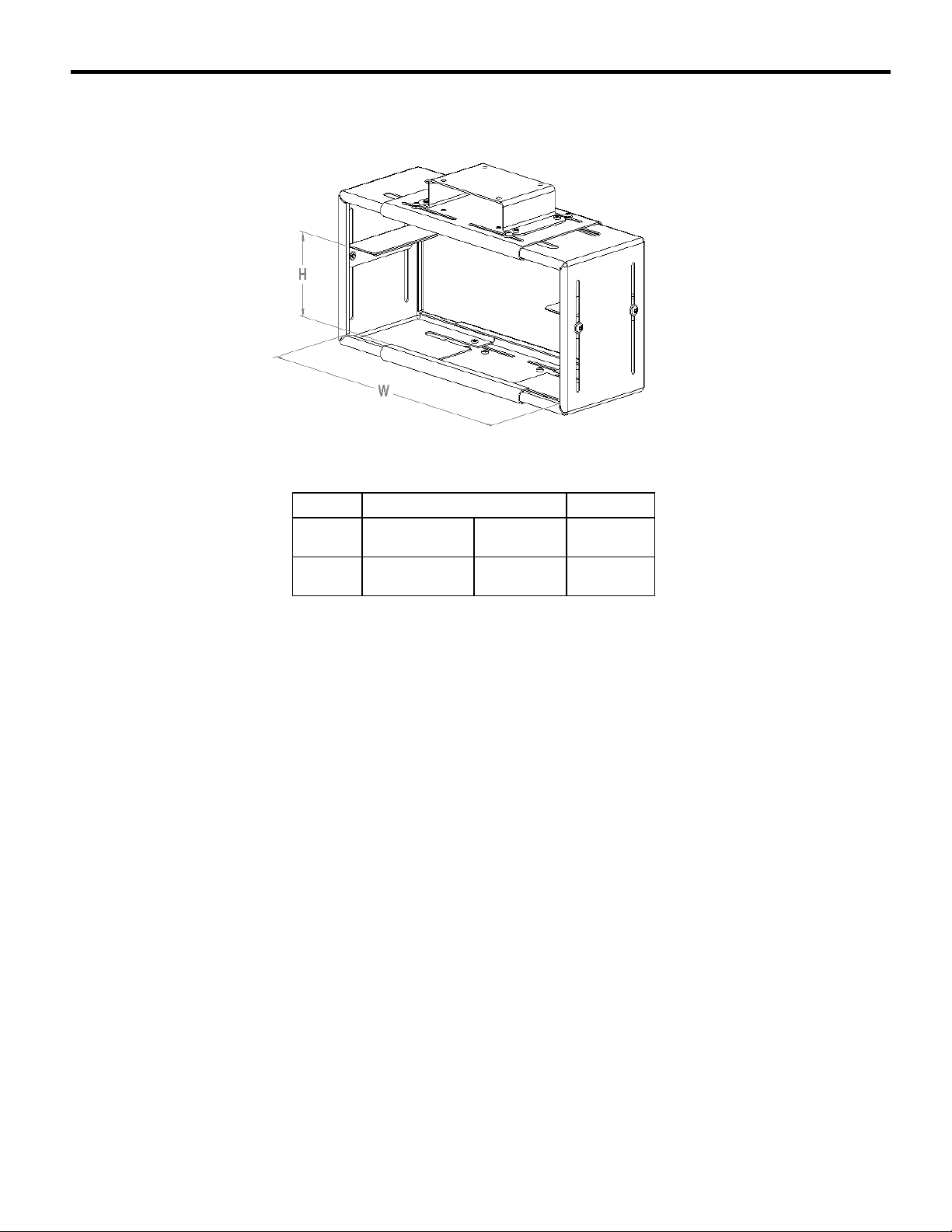
CTA-100 SPECIFICATIONS
Table 1. CTA-100 Specifications
Inside Dimensions
Model
CTA-100 10-1/4” – 17-3/8” 1” – 5-3/4”
W-Width
Adjustment
H-Height
Adjustment
Max Support
Weight
50 lbs
(22.7kg)
2
Page 3

Installation Instructions CTA-100
IMPORTANT WARNINGS and CAUTIONS!
WARNING A WARNING alerts you to the possibility of serious injury or death if you do not
follow the instructions.
CAUTION
WARNING Improper installation can result in serious personal injury! Make sure that the
WARNING Be aware of the potential for personal injury or damage to the equipment if it is not
WARNING The installer is responsible for verifying that the mounting surface to which the
WARNING The combined weight of the equipment placed on the CTA-100 must not exceed the
WARNING Watch for pinch points. Do not put your fingers between movable parts.
CAUTION
A CAUTION alerts you to the possibility of damage or destruction of equipment if you do
not follow the corresponding instructions.
mounting surface can support a redundant weight factor five times the total weight of
the equipment: if not, reinforce the mounting surface structural members before
installing the mount.
adequately mounted. Refer to the specifications described in Table 1, on page 2.
mount is anchored will safely support the combined load of all attached components or
other equipment.
maximum support weight of the mount. Refer to the specifications described in Table 1,
on page 2.
Check the unit for shipping damage before you begin the installation.
CONTENTS
CTA-100 SPECIFICATIONS...........................................2
TOOLS REQUIRED FOR INSTALLATION..................4
SHIPPING CONTENTS...................................................4
PARTS ..............................................................................4
INSTALLATION INSTRUCTIONS................................5
Assembling the Center Plates and Side Plates...............5
Attaching the Center Plates and Side Plates..................5
Installing Pads on Adjustment Plates ............................6
Installing Adjustment Plates.......................................... 6
Installing Top Attachment Plate....................................7
Connecting CTA-100 to TV/Mount ..............................7
Making Adjustments .....................................................8
Stacking Two Units ....................................................... 9
Stacking Three Units .....................................................9
3
Page 4

Installation Instructions CTA-100
TOOLS REQUIRED FOR
INSTALLATION
The tools required for installation are as follows:
• Allen Wrench (supplied)
NOTE: Other tools may be required depending on your
method of installation.
SHIPPING CONTENTS
BEFORE PROCEEDING: Unpack the carton.
Verify contents listed in Table 2.
Read installation instructions completely. If you are
missing any of the listed components, contact
Customer Service at: 1-800/582-6480.300.
Table 2. CTA-100 Parts List
ITEM DESCRIPTION QTY
10 Top Attachment Plate 1
20 Center Plate 2
30 Side Plate 2
40 Adjustment Plate 2
50 Foam Pad 2
60 M5 X 8mm Button Head Cap screw 20
70 Flat Washer 20
80 Allen Wrench 1
PARTS
70
60
10
80
40
20
50
30
Figure 1. CTA-100 Component Parts
4
Page 5

Installation Instructions CTA-100
(70)
(60)
INSTALLATION INSTRUCTIONS
STEP 1
20
Figure 2. Assemble Center Plates and Side Plates
30
20
30
Figure 3. Attach Center Plates and Side Plates
Assembling the Center Plates and Side Plates
Assemble center plates and side plates, as follows:
1. Locate two center plates (20) and two side plates
(30). See Figure 2.
NOTE: The two side plates fit inside the two center
plates. To assemble the unit, slide the two side
plates into the cuffed center plates.
2. Interconnect the first side plate (30) with both center
plates (20) as shown in Figure 2.
3. Repeat step 2 to interconnect the second side plate
(30) with the center plates (20).
Attaching the Center Plates and Side Plates
Attach center plates and side plates, as follows:
1. On the top, install four flat washers (70) and four
M5 X 8mm button head cap screws (60) into the
threaded holes in the side plates (30). See Figure 3.
2. Repeat step 1 to attach the side plates on the bottom
of the unit.
NOTE: The screws can be adjusted later when the
width of the VCR/DVD is apparent.
5
Page 6

Installation Instructions CTA-100
(40)
(70) (60)
)
(40)
(50)
STEP 2
ADJUSTMENT
PLATE
Figure 4. Install Pads on Adjustment Plates
INSTALL FOAM
PAD (50) TO
UNDERSIDE OF
TOP ADJUSTMENT
Installing Pads on Adjustment Plates
Install foam pads on adjustment plates, as follows:
1. Locate two foam pads (50) and two adjustment
plates (40). See Figure 4.
2. Remove protective tape from foam pad (50) to
expose the bond side.
3. Install foam pad (50) on underside of top adjustment
plate (40).
4. Repeat steps 2 and 3 to install the foam pad (50) on
the second adjustment plate (40).
ADJUSTMENT PLATE (40
Installing Adjustment Plates
Install top adjustment plates, as follows:
1. Install two flat washers (70) and two M5 X 8mm
button head cap screws (60) into the threaded holes
in the side plates (30). See Figure 5.
2. Repeat step 1 to install the second adjustment plate.
NOTE: The screws can be adjusted later when the
height of the VCR/DVD is apparent.
Figure 5. Install Adjustment Plates
6
Page 7

Installation Instructions CTA-100
(80)
(70)
(10)
(
)
(
)
STEP 3
Installing Top Attachment Plate
Install top attachment plate, as follows:
1. Locate the top attachment plate (10).
WARNING
Failure to install and tighten the screws
securing the top attachment plate can result in
personal injury and/or equipment damage.
2. Install four flat washers (70), four M5 X 8mm
button head cap screws (60), and the top
Figure 6. Install Top Attachment Plate
attachment plate (10) onto the bottom of the
TV/Monitor mount as shown in Figure 6.
Tighten the screws.
CTA-100
Figure 7. Connect CTA-100 to TV/Mount
TV/Mount
Connecting CTA-100 to TV/Mount
Connect the CTA-100 to the TV/Mount, as
follows:
1. Align CTA-100 with top attachment plate
(10) as shown in Figure 6.
2. Install four flat washers (70), four M5 X 8mm
button head cap screws (60) into the top
attachment plate (10). Tighten the screws.
See Figure 7.
7
Page 8

Installation Instructions CTA-100
(40)
STEP 4
Making Adjustments
1. Install your VCR/DVD into the CTA-100.
2. Adjust the side plates (30) and adjustment plates (40)
as needed to secure your VCR/DVD safely in the
CTA-100. See Figure 8.
3. Tighten all cap screws (60).
WARNING
Failure to install and tighten the screws to secure
your VCR/DVD can result in personal injury and/or
equipment damage.
and (30)
4. Check the CTA-100 to ensure that the side plates
(30) and adjustment plates (40) are adjusted
correctly. The unit should fit tightly around your
VCR/DVD. If not, repeat steps 2 and 3 until your
VCR/DVD is secure.
Figure 8. Make Adjustments to Unit
8
Page 9

Installation Instructions CTA-100
(70) (80) (10)
STEP 5 (OPTIONAL)
CONNECT SECOND ATTACHMENT PLATE
TO BOTTOM CENTER PLATE OF CTA-100.
Figure 9. Install Second Attachment Plate
Stacking Two Units
Stack two units, as follows:
1. Locate the top attachment plate (10) for the second
unit.
CAUTION
The stacked load cannot exceed 50lbs. (22.7kg).
2. Install the second attachment plate (10) on the center
plate (20) of the first CTA-100 unit. Use four flat
washers (70) and four M5 X 8mm button head cap
screws (60). Tighten the screws. See Figure 9.
3. Attach the second CTA-100 to the second attachment
plate (10). Use four flat washers (70), four M5 X 8mm
button head cap screws (60). Tighten the screws.
4. Install your VCR/DVD into the CTA-100.
5. Adjust the side plates (30) and adjustment plates (40)
as needed to secure your VCR/DVD safely in the
CTA-100.
6. Tighten all cap screws (60).
WARNING
Failure to install and tighten the screws to secure your
VCR/DVD can result in personal injury and/or
equipment damage.
7. Check the CTA-100 to ensure that the side plates (30)
and adjustment plates (40) are adjusted correctly. The
unit should fit tightly around your VCR/DVD. If not,
repeat steps 5 and 6 until your VCR/DVD is secure.
Stacking Three Units
Stack three units, as follows:
1. Perform the “Stacking Two Units” procedure to install
the third CTA-100.
CAUTION
Do not stack more than three VCR/DVD mounts from
a TV/Monitor mount. The stacked load cannot exceed
50lbs. (22.7kg).
2. Verify that all three units are secure.
9
 Loading...