

Page 1
I N S T A L L A T I O N I N S T R U C T I O N S
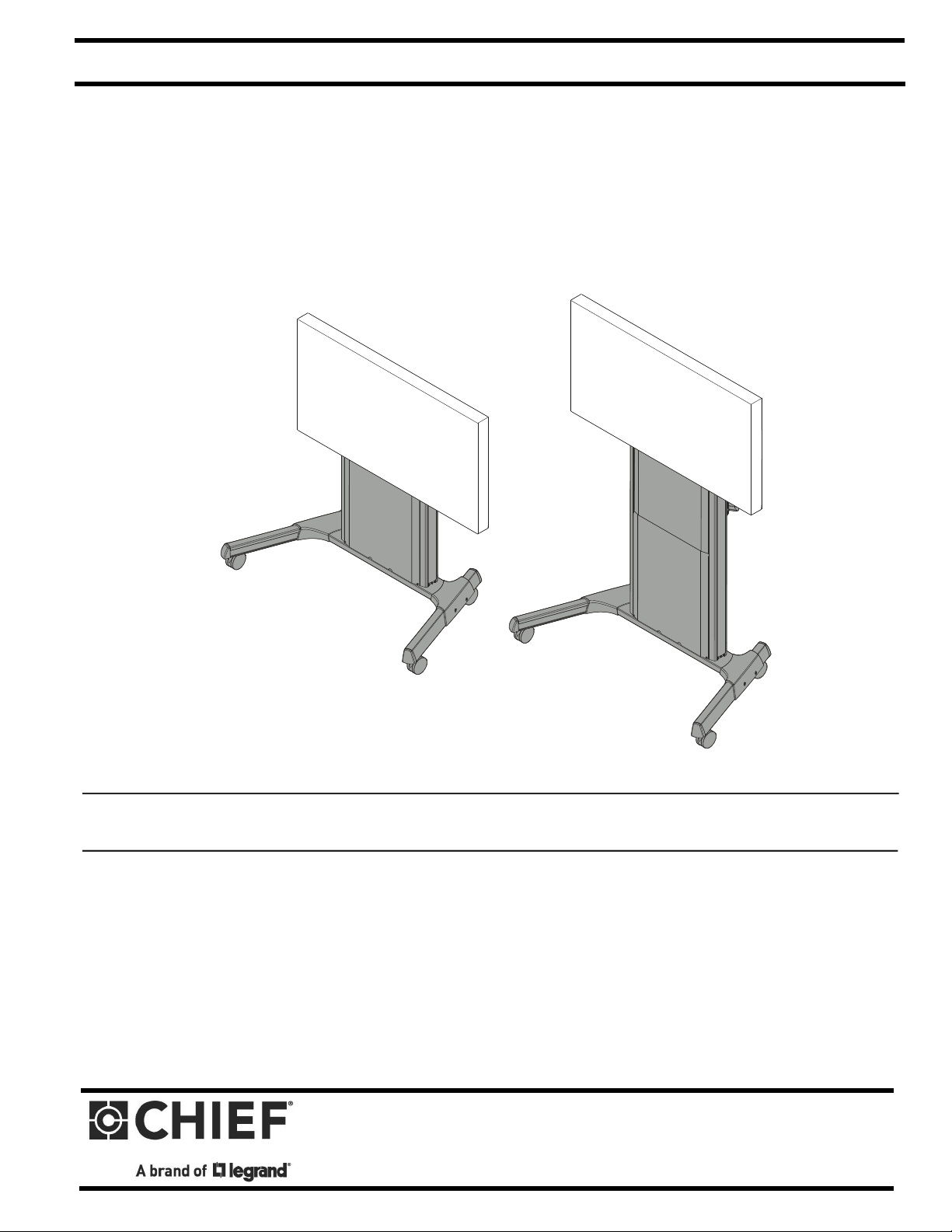
Electrical XL Height Adjustable Video Cart
Instrucciones de instalación
Installationsanleitung
Instruções de Instalação
Istruzioni di installazione
Installatie-instructies
Instructions d´installation
(Low point)
(High point)
Spanish Product Description
German Product Description
Portuguese Product Description
Italian Product Description
Dutch Product Description
French Product Description
XPD1U
Page 2
XPD1U Installation Instructions
DISCLAIMER
Legrand | AV and its affiliated corporations and subsidiaries
(collectively “Legrand | AV”), intend to make this manual
accurate and complete. However, Legrand | AV makes no claim
that the information contained herein covers all details,
conditions or variations, nor does it provide for every possible
contingency in connection with the installation or use of this
product. The information contained in this document is subject
to change without notice or obligation of any kind. Legrand | AV
makes no representation of warranty, expressed or implied,
regarding the information contained herein. Legrand | AV
assumes no responsibility for accuracy, completeness or
sufficiency of the information contained in this document.
DEFINITIONS
WARNING alerts you to the possibility of
serious injury or death if you do not follow the instructions.
CAUTION alerts you to the possibility of
damage or destruction of equipment if you do not follow the
corresponding instructions.
DANGER alerts you to an imminently
hazardous situation which, if not avoided, will result in death or
serious injury.
MOUNTING SYSTEM: A MOUNTING SYSTEM is the
primary Chief product to which an accessory and/or component
is attached.
ACCESSORY: AN ACCESSORY is the secondary Chief
product which is attached to a primary Chief product, and may
have a component attached or setting on it.
COMPONENT: A COMPONENT is an audiovisual item
designed to be attached or resting on an accessory or mounting
system such as a video camera, CPU, screen, display,
projector, etc.
ELECTRIC SHOCK:
1. Always turn off power at source before cleaning.
WARNING: TO REDUCE THE RISK OF
BURNS, FIRE, ELECTRIC SHOCK, OR INJURY TO
PERSONS:
1. Unplug from outlet before putting on or taking off parts.
2. Close supervision is necessary when this furnishing is used
by, or near children, invalids, or disabled persons.
3. Use this furnishing only for its intended use as described in
these instructions. Do not use attachments not
recommended by the manufacturer.
4. Never operate this mounting system if it has a damaged
cord or plug, if it is not working properly, if it has been
dropped or damaged, or dropped into water. Return the
mounting system to a service center for examination and
repair.
5. Keep the cord away from heated surfaces.
6. Never operate the furnishing with the air openings blocked.
Keep the air openings free of lint, hair, and the like.
7. Never drop or insert any object into any opening.
8. Do not use outdoors.
9. Do not operate where aerosol (spray) products are being
used or where oxygen is being administered.
10. To disconnect, turn all controls to the off position, then
remove plug from outlet.
11. For loading always put heavier items at the bottom and not
near the top in order to help prevent the possibility of the
furnishing tipping over.
WARNING: Exceeding the weight capacity
can result in serious personal injury or damage to equipment! It
is the installer’s responsibility to make sure the weight of all
components attached to the XPD1U does not exceed 310 lbs
(140.6 kg).
IMPORTANT SAFETY INSTRUCTIONS
WARNING: FAILURE TO READ AND FOLLOW
THE FOLLOWING INSTRUCTIONS CAN RESULT IN
SERIOUS PERSONAL INJURY, DAMAGE TO EQUIPMENT
OR VOIDING OF FACTORY WARRANTY. It is the installer’s
responsibility to make sure all components are properly
assembled and installed using the instructions provided.
When using an electrical mounting system, basic precautions
should always be followed, including the following:
READ ALL INSTRUCTIONS BEFORE USING THIS
PRODUCT!!!!
DANGER: TO REDUCE THE RISK OF
2
WARNING: Use this mounting system only
for its intended use as described in these instructions. Do not
use attachments not recommended by the manufacturer.
WARNING: Never operate this mounting
system if it is damaged. Return the mounting system to a
service center for examination and repair.
WARNING: RISK OF SERIOUS INJURY OR
DEATH! Risk of death or serious injury may occur when
children climb on audio and/or video equipment furniture. A
remote control or toys placed on the furnishing may encourage
a child to climb on the furnishing and as a result the furnishing
may tip over on to the child.
Page 3
Installation Instructions XPD1U
• Connect the equipment into an outlet on a circuit
WARNING: RISK OF SERIOUS INJURY OR
DEATH! Relocating audio and/or video equipment to furniture
not specifically designed to support audio and/or video
equipment may result in death or serious injury due to the
furnishing collapsing or overturning onto a child.
NOTE: The XPD1U cart has no user serviceable parts.
NOTE: The XPD1U cart can support screen sizes up to a
maximum of 100" wide.
NOTE: The XPD1U cart is intended for Institutional Use.
NOTE: To reduce the risk of electric shock, this furnishing has
a polarized plug (one blade is wider than the other).
This plug will fit in a polarized outlet only one way. If the
plug does not fit fully in the outlet, reverse the plug. If it
still does not fit, contact a qualified electrician to install
the proper outlet. Do not change the plug in any way.
NOTE: This product is a double-insulated, cord-connected
product and must be serviced accordingly. In a doubleinsulated product, two systems of insulation are
provided instead of grounding. No grounding means for
grounding to be added to the product Servicing a
double-insulated product requires extreme care and
knowledge of the system, and is to be done only by
qualified service personnel. Replacement parts for a
double-insulated product must be identical to the parts
they replace. A double-insulated product is marked
with the symbol (square within a square)
unit not expressly approved by the manufacturer can void the
units FCC compliance rating and make the unit illegal to
operate.
different from that to which the receiver is
connected.
• Consult the dealer or an experienced radio/TV
technician for help.
CAUTION: Changes or modifications to this
Responsible Party:
Legrand | AV
6436 City West Parkway
Eden Prairie, MN 55344
866-977-3901
av.support@legrand.com
CAN ICES-3 (B)/NMB-3(B)
--SAVE THESE INSTRUCTIONS--
Electrical Specifications
Input voltage, frequency
Duty Cycle
100-240 V~, 50-60 Hz, 450W
Intermittent: 10%; max 2
minutes on/18 minutes off
NOTE: This equipment has been tested and found to comply
with the limits for a Class B digital device, pursuant to
Part 15 of the FCC Rules. These limits are designed to
provide reasonable protection against harmful
interference in a residential installation. This equipment
generates, uses and can radiate radio frequency
energy and, if not installed and used in accordance with
the instructions, may cause harmful interference to
radio communications. However, there is no guarantee
that interference will not occur in a particular
installation. If this equipment does cause harmful
interference to radio or television reception, which can
be determined by turning the equipment off and on, the
user is encouraged to try to correct the interference by
one or more of the following measures:
• Reorient or relocate the receiving antenna.
• Increase the separation between the equipment
and receiver.
3
Page 4
XPD1U Installation Instructions
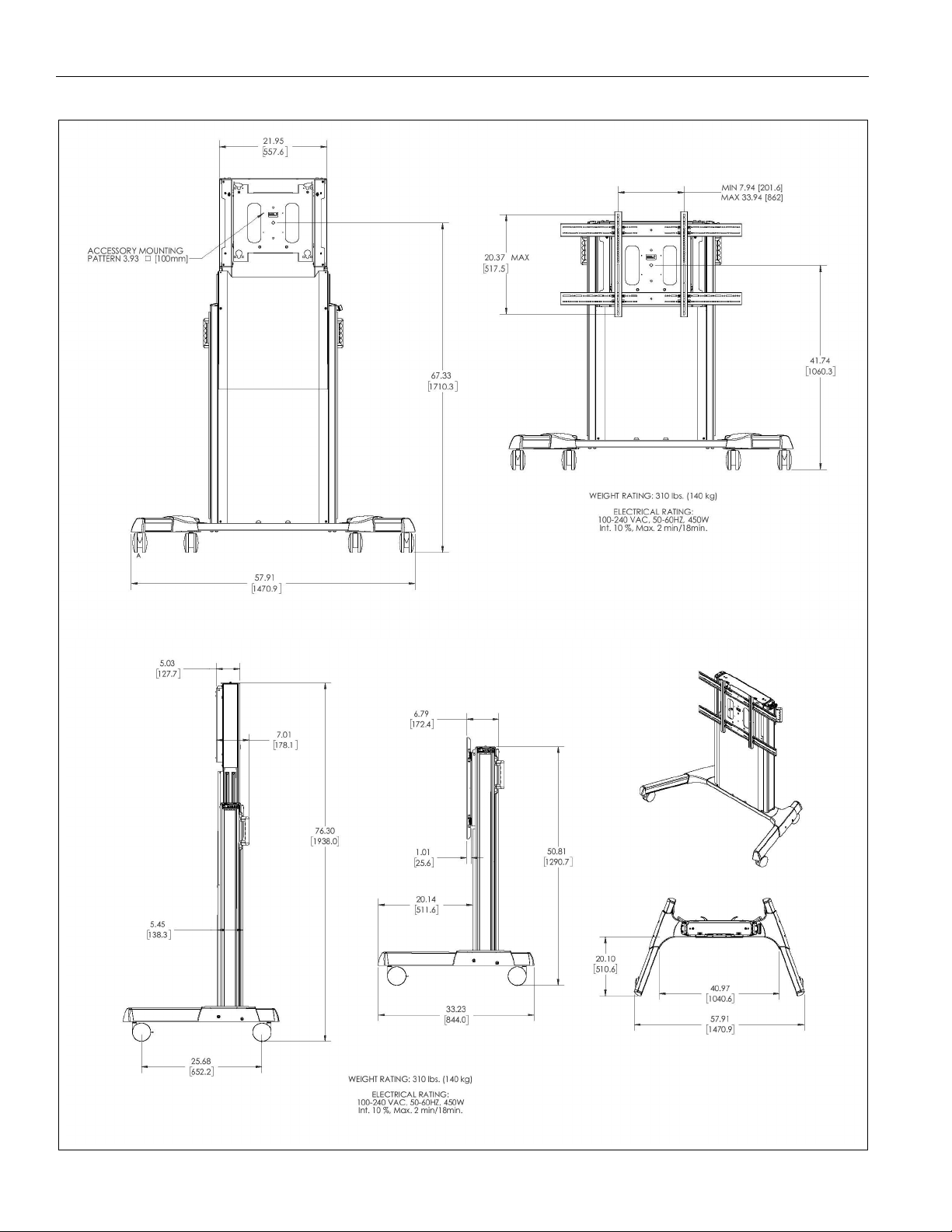
DIMENSIONS
4
Page 5
Installation Instructions XPD1U
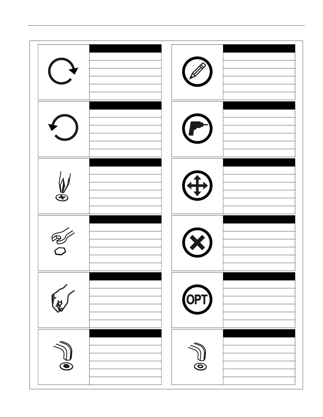
LEGEND
Tighten Fastener
Apretar elemento de fijación
Befestigungsteil festziehen
Apertar fixador
Serrare il fissaggio
Bevestiging vastdraaien
Serrez les fixations
Loosen Fastener
Aflojar elemento de fijación
Befestigungsteil lösen
Desapertar fixador
Allentare il fissaggio
Bevestiging losdraaien
Desserrez les fixations
Phillips Screwdriver
Destornillador Phillips
Kreuzschlitzschraubendreher
Chave de fendas Phillips
Cacciavite a stella
Kruiskopschroevendraaier
Tournevis à pointe cruciforme
Pencil Mark
Marcar con lápiz
Stiftmarkierung
Marcar com lápis
Segno a matita
Potloodmerkteken
Marquage au crayon
Drill Hole
Perforar
Bohrloch
Fazer furo
Praticare un foro
Gat boren
Percez un trou
Adjust
Ajustar
Einstellen
Ajustar
Regolare
Afstellen
Ajuster
Open-Ended Wrench
Llave de boca
Gabelschlüssel
Chave de bocas
Chiave a punte aperte
Steeksleutel
Clé à fourche
By Hand
A mano
Von Hand
Com a mão
A mano
Met de hand
À la main
Hex-Head Wrench
Llave de cabeza hexagonal
Sechskantschlüssel
Chave de cabeça sextavada
Chiave esagonale
Zeskantsleutel
Clé à tête hexagonale
Remove
Quitar
Entfernen
Remover
Rimuovere
Verwijderen
Retirez
Optional
Opcional
Optional
Opcional
Opzionale
Optie
En option
Security Wrench
Llave de seguridad
Sicherheitsschlüssel
Chave de segurança
Chiave di sicurezza
Veiligheidssleutel
Clé de sécurité
5
Page 6
XPD1U Installation Instructions
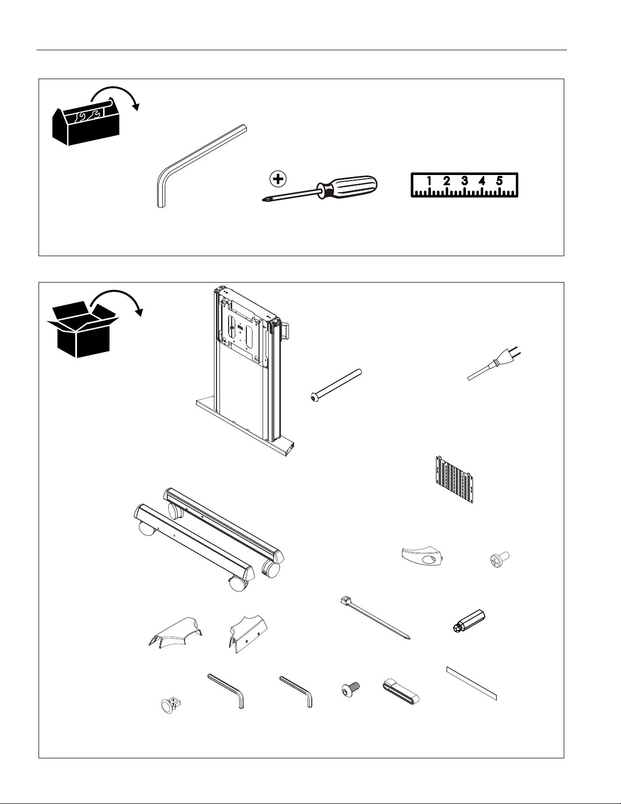
TOOLS REQUIRED FOR INSTALLATION
PARTS
1/8” (included)
3/16” (included)
A (1)
[Column assembly]
#2
D (1)
[Power cable]
B (4)
5/16-18 x 3 3/4”
E (1)
[Left cart leg]
J (1)
[Left transition cover]
N (4)
[Cable clip]
F (1)
[Right cart leg]
K (1)
[Right transition cover]
P (1)
3/16”
Q (1)
1/8”
L (8)
[Cable tie]
R (2)
#10-24 x 3/8"
[Cable hook]
S (1)
[Strap with buckle]
C (1)
[Component bracket]
G (2)
M (1)
3/16”
[Double-sided foam tape]
T (1) - Display interface + hardware
H (2)
1/4-20 x 1/2"
U (1)
(See interface parts list on page 7)
6
Page 7

XPD1U Installation Instructions
Hardware Kit
PARTS - DISPLAY INTERFACE
TR (2)
[Vertical bracket]
Bag A
TA (4)
M4 x 12mm
Bag D
TD (4)
M5 x 12mm
Bag G
TG (4)
M6 x 12mm M6 x 20mm
Bag J
TJ (4)
M8 x 12mm
Bag M
TMA (8)
[Nesting spacer]
Bag B
TB (4)
M4 x 20mm
Bag E
TE (4)
M5 x 20mm
Bag H
TH (4)
Bag K
TK (4)
M8 x 20mm
Bag C
TC (4)
M4 x 25mm
Bag F
TF (4)
M5 x 25mm
Bag I
TI (4)
M6 x 25mm
Bag L
TL (4)
M8 x 30mm
TMB (4)
[Universal spacer]
TQ (2)
[Horizontal bracket]
TN (8)
#10-24 x 1/2"
TP (1)
1/8”
7
Page 8

XPD1U Installation Instructions
Assembly And Installation
IMPORTANT ! : The XPD1U packaging was designed to
help make the installation and setup easier. Do NOT
remove assembly prior to reading installation
instructions!
Cart Assembly
1. Remove all parts and extra packaging from sides of box
leaving only the column assembly (A) in the box. (See
Figure 1)
2. Lift column assembly (A) up by lifting at the bottom of the
assembly. (See Figure 1)
3. Carefully set column assembly (A) base on the edge of box.
(See Figure 1) and (See Figure 2)
remove parts and packaging
1
(A)
3
(F)
4
(K)
4
6
5
5
(B) x 4
(E)
(J)
2
2
1
2
3
3
Figure 1
4. Place right transition cover (K) on right cart leg (F), lining up
the holes on the cover with the holes on the leg and column
assembly base. (See Figure 2)
5. Place left transition cover (J) on left cart leg (E), lining up the
holes on the cover with the holes on the leg and column
assembly base. (See Figure 2)
CAUTION: Attachment holes may be damaged if a power
drill is used to insert button head cap screws. Screws should
first be inserted and turned BY HAND with the hex key or with
a hand-held screwdriver BEFORE using the hex head drill bit
and power drill to complete the attachment.
Figure 2
7. Remove cart from box by tipping it from the top onto its
wheels. (See Figure 3)
8. Lock wheels to hold cart in position during installation.
7
6. Use four 5/16-18 x 3 3/4” button head cap screws (B) to
secure legs (E and F) and covers (K and J) to column
assembly (A). (See Figure 2)
8
Figure 3
Page 9

Installation Instructions XPD1U
9. Secure control pad into control pad bracket. (See Figure 4)
12
control pad bracket
control pad
9
Figure 4
10. Remove bottom two screws from back cover. (See Figure 5)
11. Loosen top two screws from back cover. (See Figure 5)
12. Remove back cover by lifting cover up and out. (See Figure
5)
11
10
loosen x 2
x 2
Figure 5
13. Plug in power cable (C) to power supply. Provide strain relief
using the cable tie on nearest cable clip. (See Figure 6)
power
supply
13
Figure 6
9
Page 10

XPD1U Installation Instructions
14. (Optional) Place component bracket (C) in mounting
position. (See Figure 7)
15. (Optional) Use two #10-24 x 3/8" button head cap screws
(R) to secure component bracket. (See Figure 7)
NOTE: Strap with buckle (S) and/or cable ties (L) may be used
to secure components to component bracket (C).
14
"UP"
19. Remove bottom two screws from front cover. (See Figure 9)
20. Use finger tabs to pull front cover out and slide down. Cover
must be flexed to remove pins from uprights in order to
remove. (See Figure 9)
"DOWN"
"PRESETS"
Figure 8
"SAVE"
15
(R) x 2
Figure 7
16. Plug in power cable to outlet.
17. Press and hold "DOWN" button for three seconds to
initialize lift mechanism. (See Figure 8)
18. Press and hold "UP" button until mount reaches it’s
maximum height. (See Figure 8)
NOTE: If lifting mechanism does not function properly refer to
"Troubleshooting" Section.
19
20
x 2
Figure 9
10
Page 11

Installation Instructions XPD1U
21. Attach display and signal cables to power source. Use cable
clips (N) and cable ties (L) to route as necessary. (See
Figure 10)
IMPORTANT ! : Make sure to install cables when lift is at
the highest position and so that there is enough length to
reach input locations for display and signal.
enough distance to
reach inputs
21
recommended strain relief
(pre-installed cable clips)
locations
22. (Optional) Relocate control pad to the front center of display
if desired following these steps. (See Figure 11)
• A. Unplug control box cable from control box.
• B. Remove cable through side cable cover.
• C. Pull cable out through opening at bottom of
cable cover.
• D. Feed removed cable down through center
channel.
• E. Plug cable back into control box.
• F. Use double-sided foam tape (R) to attach
control pad to bottom of display in the center.
B
signal cable
to signal box
(example)
power cable
(example)
(pre-installed cable clips)
A
C
F
D
additional cable tie locations
if extra cable clips (H) are used
recommended strain relief
locations
E
additional cable tie locations
if extra cable clips (N) are used
Figure 10
recommended strain relief
locations
(pre-installed cable clips)
Figure 11
11
Page 12

XPD1U Installation Instructions
23. Reinstall front cover by using two screws removed in Step
19. (See Figure 12)
23
22
x 2
Figure 12
24. Reinstall rear cover and secure by installing screws
removed in Step 10. (See Figure 13)
25. Tighten screws that were loosened in Step 11. (See Figure
13)
26. Use two 1/4-20 x 1/2” Phillips pan machine screws (H) to
attach two cable hooks (G) to bottom of column assembly
(A). (See Figure 14)
(A)
25
(G) x 2
(H) x 2
Figure 14
Display Installation
WARNING: Exceeding the weight capacity can result in
serious personal injury or damage to equipment! It is the
installer’s responsibility to make sure the combined weight of
all accessories and components attached to the XPD1U head
assembly up to (and including) the display does not exceed
310 lbs (140.6 kg).
1. Make sure height is at the lowest possible position.
2. Make sure latching flags are in "open" position.
23
23
Figure 13
24
WARNING: IMPROPER INSTALLATION CAN LEAD TO
MOUNT FALLING CAUSING SERIOUS PERSONAL
INJURY OR DAMAGE TO EQUIPMENT! DO NOT substitute
hardware. Only use hardware provided or specified by
manufacturer.
tighten x 2
x 2
12
Page 13

XPD1U Installation Instructions
3. Determine and mark the vertical center position between
the Left side Upper and Lower mounting holes in display.
(See Figure 15)
4. Determine and mark the vertical center position between
the Right side Upper and Lower mounting holes in display.
(See Figure 15)
(TR) x 2
Mounting holes
3
6
Mounting Slots
7. Adjust vertical mounting bracket (TR) position until mark
made in Step 1 aligns with center mark in vertical mounting
bracket (TR).
8. Select correct screws, nesting spacers (if necessary) and
universal washers (if required) from the hardware bag (TATM) and attach brackets to back of screen. (See Figure 17)
IMPORTANT ! : The M8 screws do NOT require a
washer. Use the universal washer (TMB) only with M4,
M5 and M6 screws.
NOTE: The nesting spacers (TMA) may be used separately, or
put two together in different configurations to create
different size spacers. (See Figure 16)
(Single) (Nested) (Stacked)
0.375
[9.5]
0.563
[14.3]
0.750
[19.1]
Figure 16
9. If the display has a recessed mounting surface, protrusions
or a power box, a spacer and longer mounting hardware
must be placed between the display and vertical mounting
bracket (TR). (See Figure 17)
10. Repeat Steps 5 through 8 for Right side vertical mounting
bracket using the same hole locations to align brackets
horizontally.
Figure 15
5. Orient vertical mounting bracket (TR) so that mounting
holes are on top and mounting slots are on bottom. (See
Figure 15)
6. Align mounting holes in vertical mounting bracket (TR) with
upper and lower mounting holes in display.
10
8
(TR) x 2
(TMA) x 4
(TMB) x 4
(TR)
(TA through TL)
x 4
13
Figure 17
Page 14

XPD1U Installation Instructions
11. Determine and mark the horizontal center position between
the Left and Right TOP mounting holes in display.
(See Figure 18)
12. Determine and mark the horizontal center position between
the Left and Right BOTTOM mounting holes in display. (See
Figure 18)
13. Orient upper horizontal mounting bracket (TQ) so that
flanges are facing towards display and resting in recessed
area of left and right vertical mounting brackets (TR). (See
Figure 18)
14. Adjust Upper horizontal mounting bracket (TQ) position until
center diamond in horizontal mounting bracket (TU) aligns
with mark made in Step 11, and mounting holes and slots in
horizontal mounting bracket (TQ) are aligned with threaded
holes in mounting tabs of left and right vertical mounting
brackets (TR). (See Figure 18) and (See Figure 19)
15. Use 1/8" hex key (TP) to secure upper horizontal mounting
bracket (TQ) to left and right vertical mounting brackets
(TR) using four button head flanged screws (TN). (See
Figure 19)
16. Repeat Steps 12 through 15 for lower horizontal mounting
bracket (TQ).
IMPORTANT ! : The orientation of, and mounting holes used,
when installing the lower horizontal mounting bracket must be
the same as the upper horizontal mounting bracket. Vertically
align upper and lower brackets by aligning holes or end of slots.
(See Figure 19)
IMPORTANT ! : Whenever possible install mounting
screws diagonally as shown in detail in Figure 18.
17. Install display with attached universal interface and move
flags to "closed" position to secure display to mount. (See
Figure 20)
11
(TQ) x 2
(TR) x 2
Figure 18
12
Center Mark
(TR) x 2
15
(TR) x 2
15
14
(TN) x 8
(TQ) x 2
Figure 19
14
Page 15

Installation Instructions XPD1U
18. Make sure latching flags are in "closed" position prior to
using cart!
IMPORTANT ! : Manufacturer recommends using cable
ties (Z) to secure the latching flags in closed position on
both sides if padlock is not being used. (See Figure 20)
(Z) x 2
flags
"closed"
Figure 20
Adjustments
Height Adjustment
1. Press "UP" or "DOWN" buttons to raise or lower height as
desired. (See Figure 21)
"UP"
"DOWN"
"PRESETS"
"SAVE"
• Turn Counterclockwise to lower
• Turn Clockwise to raise
lower
raise
Figure 22
Cart Use and Maintenance
WARNING: Exceeding the weight capacity can result in
serious personal injury or damage to equipment! It is the
installer’s responsibility to make sure the combined weight of
all accessories and components attached to the XPD1U head
assembly up to (and including) the display does not exceed
310 lbs (140.6 kg). Use with heavier televisions may result in
instability causing tip over resulting in death or serious injury.
See Figure below for reference.
Figure 21
Save Height Levels
1. Adjust height until desired preset level is reached using
"UP" and "DOWN" buttons. (See Figure 21)
2. Press "SAVE" button. (See Figure 21)
3. Press one of three preset buttons (., .. or ...) to save preset
position. (See Figure 21)
4. Repeat Steps 1-3 as desired.
Leveling Adjustment
1. Use 3/16" hex key to adjust leveling adjustment screws on
top of cart. (See Figure 22)
WARNING: RISK OF SERIOUS INJURY OR DEATH!
Placing a remote control or toy on the cart may encourage a
child to climb onto the cart causing the cart to tip over onto
the child. DO NOT place remote controls or toys on the cart!
WARNING: RISK OF SERIOUS INJURY OR DEATH!
Relocating audio and/or video equipment to the cart may
result in the cart collapsing or overturning onto a child. DO
NOT relocate audio and/or video equipment to the cart!
WARNING: CART CAN TIP OVER RESULTING IN
INJURY! Do not allow children under 16 to move cart. Only
adults should move this cart.
WARNING: CART CAN TIP OVER RESULTING IN
INJURY! Move cart slowly and with the cart set at its lowest
position. Use handles for additional stability. Push, don’t pull
cart. (See Figure 23)
NOTE: The XPD1U cart has no user serviceable parts.
15
Page 16

XPD1U Installation Instructions
NOTE: The XPD1U cart can support screen sizes up to a
maximum of 100" wide.
NOTE: The XPD1U cart is intended for institutional use.
1. Always place cart on a level surface.
Push cart using handles
Only move cart
at its lowest
height position!
3
x 4
Figure 25
Troubleshooting
If lifting function does not work properly, try to following
troubleshooting steps. If none of these work, contact customer
service.
1. If there is uneven movement, initialize the control box
(reset)
• Hold "Down" button until lift has reached it’s lower
Figure 23
2. Always lock the wheels when the cart is not moving by
pressing down the locks on wheels. (See Figure 24)
2. If there is no movement, check the following
3. If there is slight movement and then reverse travel, check
4. Contact customer service if none of the above steps fix the
limit.
• Briefly release "Down" button
• Press and hold "Down" for five seconds, wait until
all movement has stopped, then release
• Check all cable connectors between controllers
and actuators.
• Check power cable connection to control box.
for any obstructions that may be interfering such as cables
or peripheral devices.
problem.
2
Figure 24
3. Check and tighten the hex nuts on the casters occasionally.
(See Figure 25) These should be checked especially after
use on uneven ground.
16
Page 17

Installation Instructions XPD1U
17
Page 18

XPD1U Installation Instructions
18
Page 19

Installation Instructions XPD1U
19
Page 20

XPD1U Installation Instructions
8800-003011 Rev04
2019 Legrand | AV
www.legrandav.com
03/19
USA/International A 6436 City West Parkway, Eden Prairie, MN 55344
P 800.582.6480 / 952.225.6000
F 877.894.6918 / 952.894.6918
Europe A Franklinstraat 14, 6003 DK Weert, Netherlands
P +31 (0) 495 580 852
F +31 (0) 495 580 845
Asia Pacific A Office No. 918 on 9/F, Shatin Galleria
18-24 Shan Mei Street
Fotan, Shatin, Hong Kong
P 852 2145 4099
F 852 2145 4477
 Loading...