

CHIEF X462UN-TMX4D, X461UNV, X462UN, Video Wall Mount WM-46UN Chief, QMP1L Installation Instructions Manual
...Page 1
INSTALLATION INSTRUCTIONS
Instrucciones de instalación
Installationsanleitung
Instruções de Instalação
Istruzioni di installazione
Installatie-instructies
Instructions d´installation
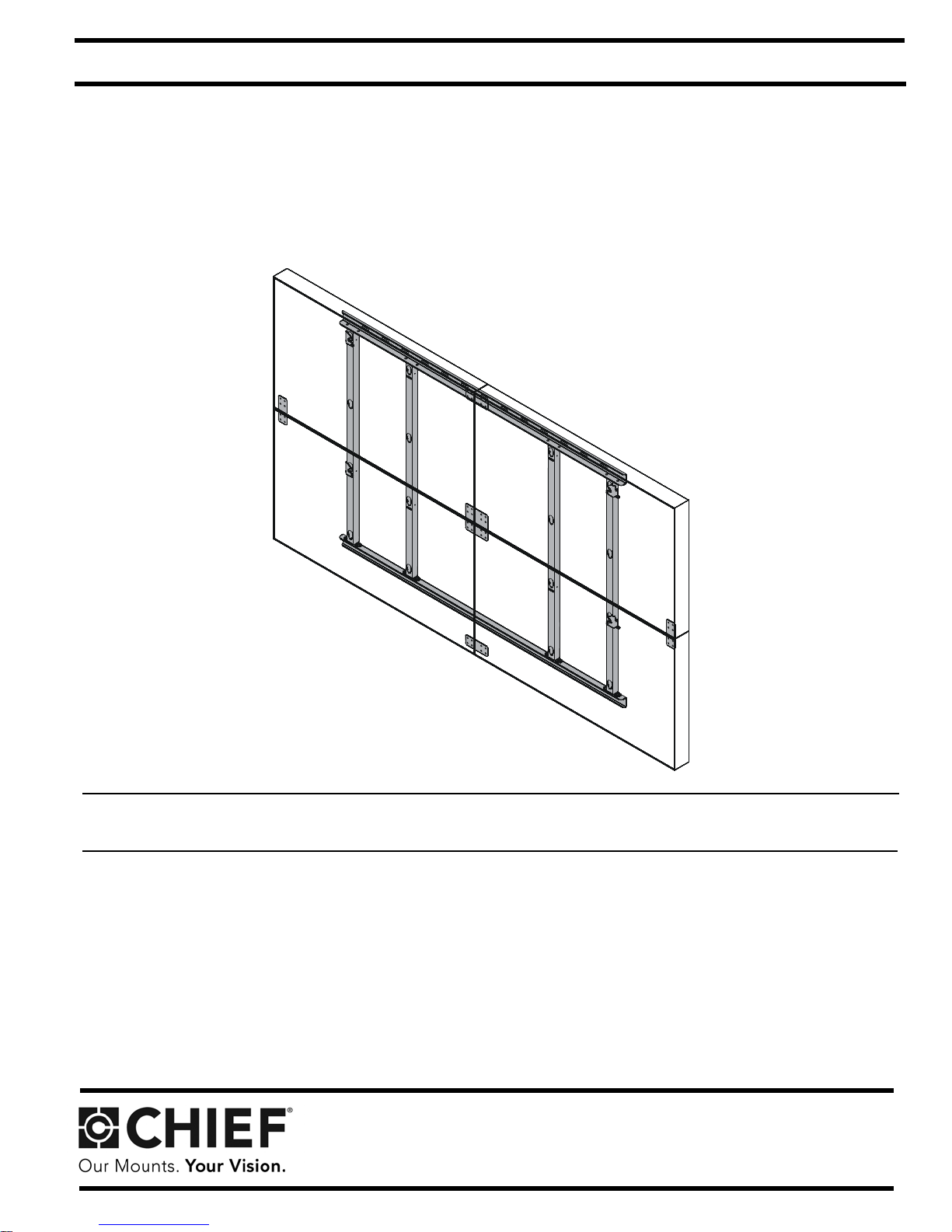
2 X 2 Array Wall Mount
Spanish Product Description
German Product Description
Portuguese Product Description
Italian Product Description
Dutch Product Description
French Product Description
MSP-WM46UN2X2
Page 2
MSP-WM46UN2X2 Installation Instructions
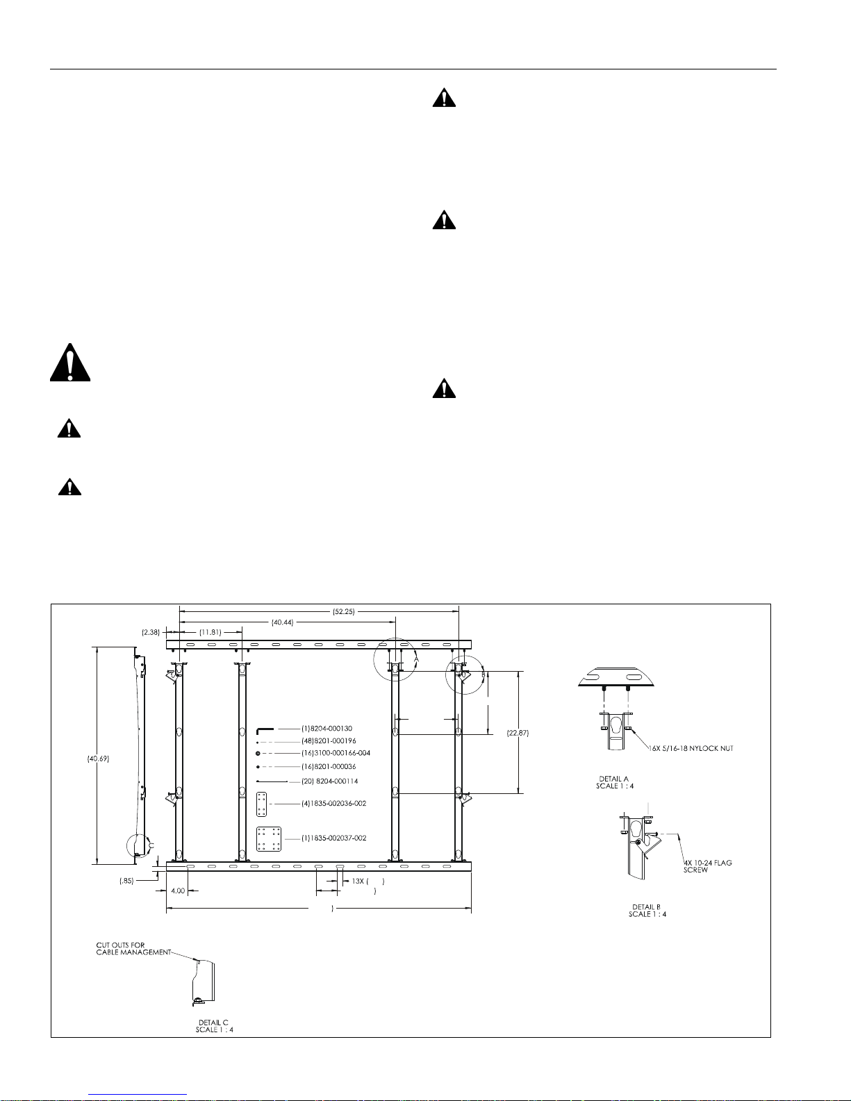
(300MM)
(300MM)
(57.00
12X (
4.00
1.00
DISCLAIMER
Milestone AV Technologies and its affiliated corporations and
subsidiaries (collectively "Milestone"), intend to make this
manual accurate and complete. However, Milestone makes no
claim that the information contained herein covers all details,
conditions or variations, nor does it provide for every possible
contingency in connection with the installation or use of this
product. The information contained in this document is subject
to change without notice or obligation of any kind. Milestone
makes no representation of warranty, expressed or implied,
regarding the information contained herein. Milestone assumes
no responsibility for accuracy, completeness or sufficiency of
the information contained in this document.
Chief® is a registered trademark of Milestone AV T echnologies.
All rights reserved.
WARNING:
follow all instructions can result in serious personal injury,
damage to equipment, or voiding of factory warranty! It is the
installer’s responsibility to make sure all components are
properly assembled and installed using the instructions
provided.
WARNING:
for this component can result in serious personal injury or
damage to equipment! It is the installer’s responsibility to
make sure the structure to which this component is attached
can support a minimum of five times the weight of the mount
and displays being mounted. Reinforce the structure as
required before installing the component. The wall to which
the mount is being attached may have a maximum drywall
thickness of 5/8" (1.6cm).
Failure to read, thoroughly understand, and
Failure to provide adequate structural strength
IMPORTANT WARNINGS AND
CAUTIONS!
WARNING:
serious injury or death if you do not follow the instructions.
CAUTION:
damage or destruction of equipment if you do not follow the
corresponding instructions.
A WARNING alerts you to the possibility of
A CAUTION alerts you to the possibility of
WARNING:
Exceeding the weight capacity can result in
serious personal injury or damage to equipment! It is the
installer’s responsibility to make sure the combined weight of
all components attached to the MSP-WM46UN2X2 mount
does not exceed 280 lbs (127 kg). The weight of each
individual display cannot exceed 70 lbs (31.75 kg).
DIMENSIONS
2
Page 3
Installation Instructions MSP-WM46UN2X2
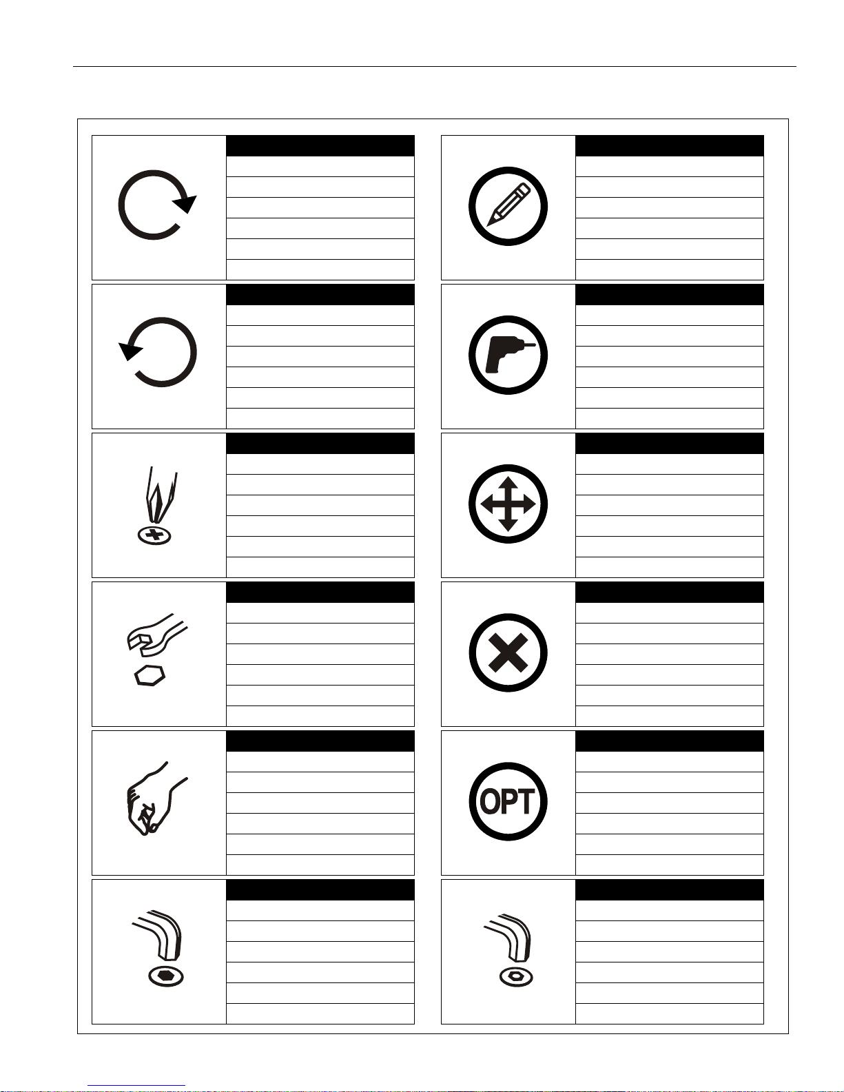
Tighten Fastener
Apretar elemento de fijación
Befestigungsteil festziehen
Apertar fixador
Serrare il fissaggio
Bevestiging vastdraaien
Serrez les fixations
Loosen Fastener
Aflojar elemento de fijación
Befestigungsteil lösen
Desapertar fixador
Allentare il fissaggio
Bevestiging losdraaien
Desserrez les fixations
Phillips Screwdriver
Destornillador Phillips
Kreuzschlitzschraubendreher
Chave de fendas Phillips
Cacciavite a stella
Kruiskopschroevendraaier
Tournevis à pointe cruciforme
Open-Ended Wrench
Llave de boca
Gabelschlüssel
Chave de bocas
Chiave a punte aperte
Steeksleutel
Clé à fourche
By Hand
A mano
Von Hand
Com a mão
A mano
Met de hand
À la main
Hex-Head Wrench
Llave de cabeza hexagonal
Sechskantschlüssel
Chave de cabeça sextavada
Chiave esagonale
Zeskantsleutel
Clé à tête hexagonale
Pencil Mark
Marcar con lápiz
Stiftmarkierung
Marcar com lápis
Segno a matita
Potloodmerkteken
Marquage au crayon
Drill Hole
Perforar
Bohrloch
Fazer furo
Praticare un foro
Gat boren
Percez un trou
Adjust
Ajustar
Einstellen
Ajustar
Regolare
Afstellen
Ajuster
Remove
Quitar
Entfernen
Remover
Rimuovere
Verwijderen
Retirez
Optional
Opcional
Optional
Opcional
Opzionale
Optie
En option
Security Wrench
Llave de seguridad
Sicherheitsschlüssel
Chave de segurança
Chiave di sicurezza
Veiligheidssleutel
Clé de sécurité
LEGEND
3
Page 4
MSP-WM46UN2X2 Installation Instructions
3/8" (9.5mm)-concrete #2
3/8" (9.5mm)
1/4" (6.35mm)-wood
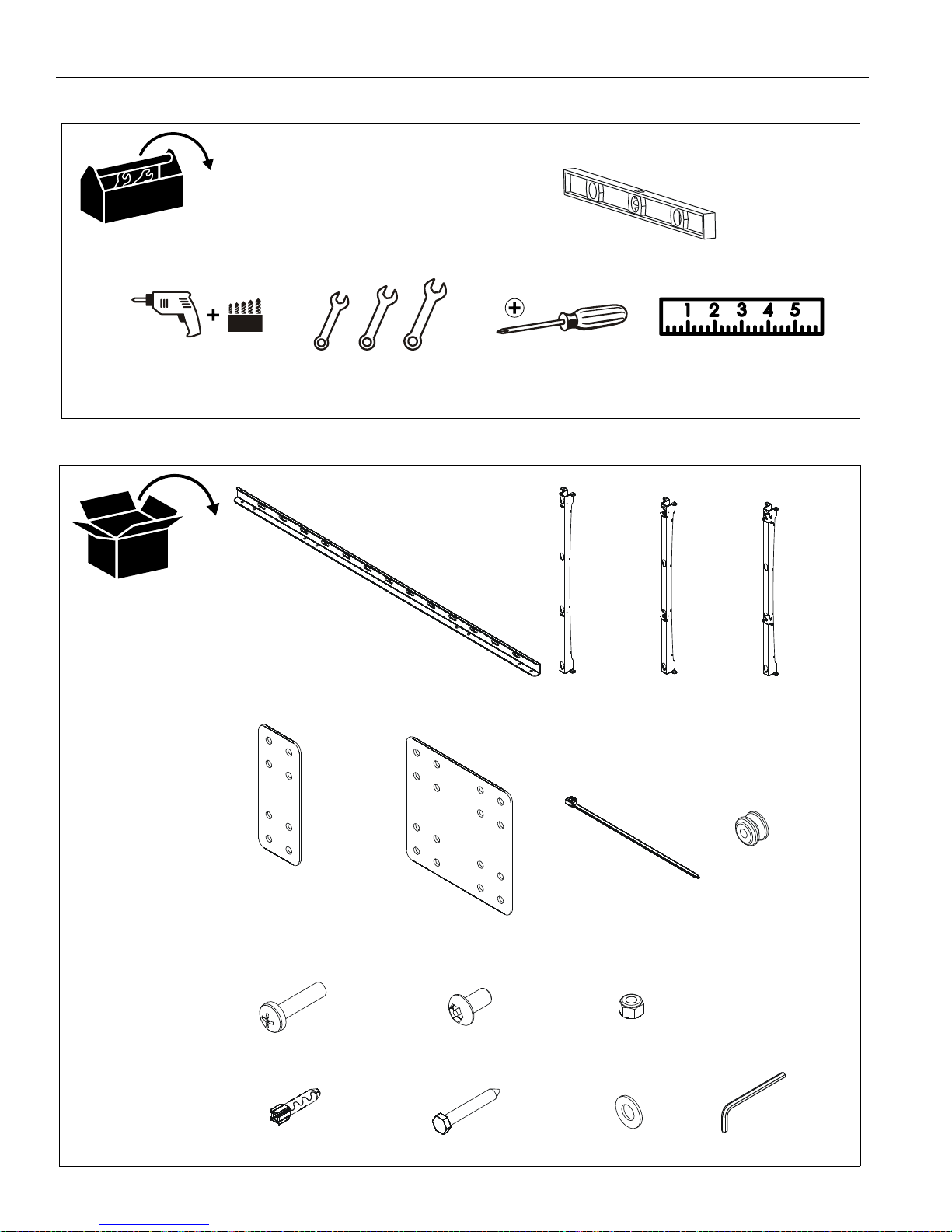
A(2)
[horizontal wall bracket]
B(2)
[vertical bracket]
C(1)
[left vertical bracket]
D(1)
[right vertical bracket]
E(4)
[edge attachment bracket]
F(1)
[middle attachment bracket]
G(20)
[cable tie]
H(16)
[mounting button]
J(16)
M6 x 25mm
K(48)
M4 x 8mm
L(16)
5/16-18"
M(4)
[A10 anchor]
N(4)
3/8 x 2 1/2"
P(4)
3/8"
Q(1)
M5
(security)
TOOLS REQUIRED FOR INSTALLATION
PARTS
4
Page 5

Installation Instructions MSP-WM46UN2X2
(B) x 2
(L) x 16
2
(C)
(D)
(A) x 2
24" min. centered
24" min.(4 1/2" right)
24" min.(4 1/2" left)
(M) x 4
5
6
(N) x 4
3
4
x 4
ASSEMBLY AND INSTALLATION
Mount Assembly
1. Arrange four vertical brackets (B-D) with two horizontal
brackets (A) making sure the right vertical bracket (C) is on
the far right and the left vertical bracket (D) is on the far left.
(See Figure 1)
2. Use 16 5/16-18" lock nuts (L) to attach vertical brackets to
horizontal brackets. (See Figure 1)
Figure 2
3. Using assembled mount as a template, mark four holes in
selected mounting holes on wall. Use a level to make sure
of an even mount. (See Figure 3)
4. Drill four 3/8" holes in wall 2 1/2" deep at marked locations.
(See Figure 3)
5. Install four concrete anchors (M) into four drilled holes on
wall. (See Figure 3)
6. Install four 3/8 x 2 1/2" hex head lag screws (N) through
holes on mount and into four concrete anchors. (See Figure
3)
Attach Mount to Wall - Concrete
NOTE:
1. Determine mounting location on wall.
2. Determine mounting slots to be used for installation. (See
Note below and Figure 2)
NOTE:
Figure 1
If attaching to wood studs, proceed to Attach Mount to
Wall - Wood Studs section.
Slots used must be at least 24" apart. Mount must be
centered on anchors +/- 4 1/2". (See Figure 2)
Figure 3
5
Page 6

MSP-WM46UN2X2 Installation Instructions
24" studs
16" studs
center on 2 studs
+/- 4 1/2"
center on 3 studs
+/- 4 1/2"
3
4
x 4
5
(N) x 4
(H) x 4
(J) x 4
3
Attach to Wall - Wood Studs
1. Determine mounting location on wall.
2. Determine mounting slots to be used for installation. (See
Note below and Figure 4)
NOTE:
If mounting to center of 24" studs, slots used must be
centered +/- 4 1/2". For 16" studs, slots used must be
centered over three studs +/- 4 1/2". (See Figure 4)
Figure 5
Install Displays
WARNING:
serious personal injury or damage to equipment! It is the
installer’s responsibility to make sure the combined weight of
all components attached to the MSP-WM46UN2X2 mount
does not exceed 280 lbs (127 kg). The weight of each
individual display cannot exceed 70 lbs (31.75 kg).
1. Use four M6 x 25mm Phillips pan machine screws (J) to
Figure 4
attach four mounting buttons (H) to center holes on back of
display. (See Figure 6)
2. Repeat Step 1 for each display to be installed.
3. Using assembled mount as a template, mark four holes on
wall. Use a level to make sure of an even mount. (See
Figure 5)
4. Drill four 1/4" holes 2 1/2" deep in wall at marked locations.
(See Figure 5)
5. Install four 3/8 x 2 1/2" hex head lag screws (N) through
holes on mount and into four drilled holes on wall. (See
Figure 5)
Exceeding the weight capacity can result in
6
Figure 6
Page 7

Installation Instructions MSP-WM46UN2X2
flags in open position
3
3
2
1
4
3
4
(display hidden for
7
5
6
slot for cable
management
viewing purposes)
3. Make sure locking flags on mount are in open position. (See
Figure 7)
Figure 9
Figure 7
IMPORTANT ! : For proper installation, the four displays
MUST be installed in the EXACT ORDER specified in
these instructions and shown in Figure 8.
5. Move locking flag to closed position by wrapping it around
mounting button. (See Figure 10)
6. Slide flag towards center of the mount to secure flag around
mouting button. (See Figure 10)
7. Tighten screw to push mounting button towards center of
mount and further secure display to mount. (See Figure 10)
4. Lift display onto mount by inserting mounting buttons into
teardrop openings on vertical mounting brackets. (See
Figure 9)
Figure 8
Figure 10
NOTE:
8. Repeat Steps 4 through 7 for top left display.
Slots on vertical brackets can be used for cable
management by using cable ties (G) to secure cables
to brackets. (See Figure 10)
7
Page 8

MSP-WM46UN2X2 Installation Instructions
(F)
(E)
10
(K) x 8
12
(K) x 4
11
(K) x 8
13
(K) x 4
(E)
(E)
(back view)
15
(K) x 4
16
(K) x 4
17
(K) x 4
(E)
(F)
(E)
19
(K) x 4
20
(K) x 4
(F)
(F)
vacant
9. Place one edge attachment bracket (E) behind installed
displays, lining up the eight holes with the four holes in the
upper left corner of the bottom display and the lower left
corner of the top display. (See Figure 11)
10. Install eight M4 x 8mm security screws (K) through edge
attachment bracket (E) and into backs of displays. (See
Figure 11)
Figure 11
1 1. Install eight M4 x 8mm security screws (K) through holes of
middle attachment bracket (F) and into lower right holes of
upper display and upper right holes of lower display. (See
Figure 11)
12. Install four M4 x 8mm security screws (K) through holes of
edge attachment bracket (E) and into upper right holes of
upper display. (See Figure 11)
13. Install four M4 x 8mm security screws (K) through holes of
edge attachment bracket (E) and into lower right holes of
lower display. (See Figure 11)
14. Repeat Steps 4 through 7 to install bottom right display.
15. Install four M4 x 8mm security screws (K) through holes of
edge attachment bracket (E) and into upper right holes of
lower right display. (See Figure 12)
16. Install four M4 x 8mm security screws (K) through holes of
middle attachment bracket (F) and into upper left holes of
lower right display. (See Figure 12)
17. Install four M4 x 8mm security screws (K) through holes of
edge attachment bracket (E) and into lower left holes of
lower right display. (See Figure 12)
Figure 12
18. Repeat Steps 4 through 7 to install top right display .
19. Install four M4 x 8mm security screws (K) through holes of
edge attachment bracket (E) and into upper left holes of
upper right display. (See Figure 13)
20. Install four M4 x 8mm security screws (K) through holes of
edge attachment bracket (E) and into lower right holes of
upper right display. (See Figure 13)
8
Figure 13
Page 9

Installation Instructions MSP-WM46UN2X2
9
Page 10

MSP-WM46UN2X2 Installation Instructions
10
Page 11

Installation Instructions MSP-WM46UN2X2
11
Page 12

MSP-WM46UN2X2 Installation Instructions
Chief Manufacturing, a products division
of Milestone AV Technologies
8840-002001 Rev 00
©2009 Milestone Technologies, a
Duchossois Group Company
www.chiefmfg.com
07/09
USA/International A 8401 Eagle Creek Parkway, Savage, MN 55378
P 800.582.6480 / 952.894.6280
F 877.894.6918 / 952.894.6918
Europe A Fellenoord 130 5611 ZB EINDHOVEN, The Netherlands
P +31 (0)40 2668620
F +31 (0)40 2668615
Asia Pacific A Room 24F, Block D, Lily YinDu International Building
LuoGang, BuJi Town, Shenzhen, CHINA.
P +86-755-8996 92 26
F +86-755-8996 9217
 Loading...