

Page 1
INSTALLATION INSTRUCTIONS
SLB-U
UNIVERSAL SLB
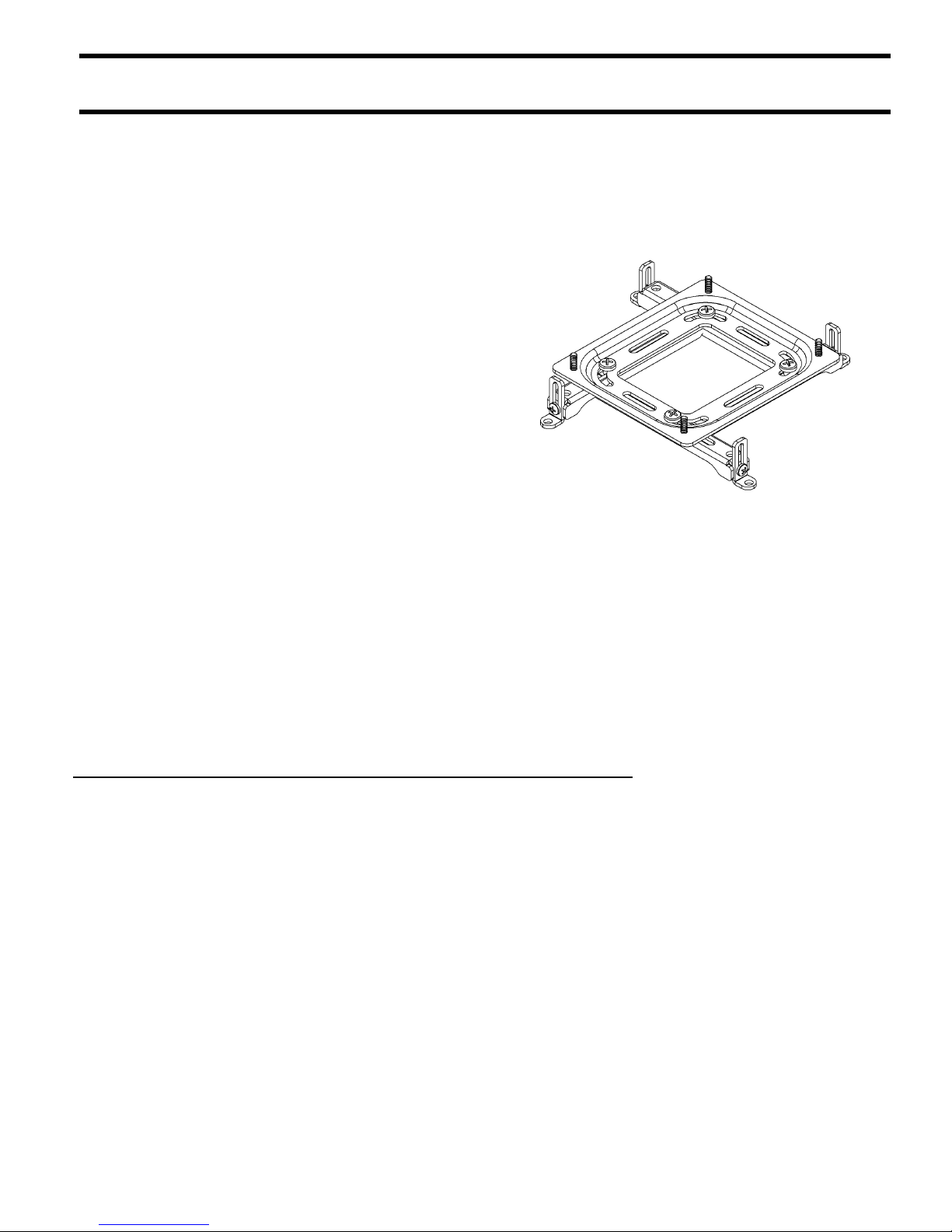
The Universal Smart Lift Bracket™ (SLB-U) provides a
solution for simplifying inventory of RPA series mounts
and SLB-U projector brackets.
The SLB-U allows for exact alignment with the
projector. The projector can be shifted around on the
mounting plate until its weight is centered and balanced.
The SLB-U is equipped with adjustable legs and feet,
which can be moved to any angle, depending on the
mounting-hole pattern on the projector. Leg and foot
length, width, and height can readily be adjusted.
The SLB-U is shipped with All-Points™ Security
System hardware, which is designed to protect projectors
from theft. Chief Manufacturing provides the security kit
exclusively.
BEFORE YOU BEGIN
SLB-U
• CAUTION: To prevent damage to your monitor, which could affect or void the Factory warranty,
thoroughly study all instructions and illustrations before you begin to install the mount brackets. Pay
particular attention to the Warnings and Cautions in this document.
• If you have any questions about this installation, us at 1-800-888-6024
Page 2
Installation Instructions SLB-U
IMPORTANT WARNINGS and CAUTIONS!
WARNING
CAUTION
• WARNING
• WARNING
• WARNING
• WARNING
• CAUTION
A WARNING alerts you to the possibility of serious injury or death if you do not follow the
instructions.
A CAUTION alerts you to the possibility of damage or destruction of equipment if you do not follow
the corresponding instructions.
Be aware of the potential for personal injury or damage to the equipment if it is not installed
correctly. Consider the weight of the projector mount without the projector.
The installer is responsible for verifying that the projector to which the universal mount is
fastened will safely support the combined load of all attached components or other equipment.
The combined weight of the projector placed on the universal mount must not exceed the
maximum support weight of the projector.
Watch for pinch points. Do not put your fingers between movable parts.
Check the unit for shipping damage before you begin the installation.
TOOLS REQUIRED FOR
INSTALLATION
• Phillips screwdriver
• 5/32” Allen Wrench
• Level
NOTE: Other tools may be required depending on your
method of installation.
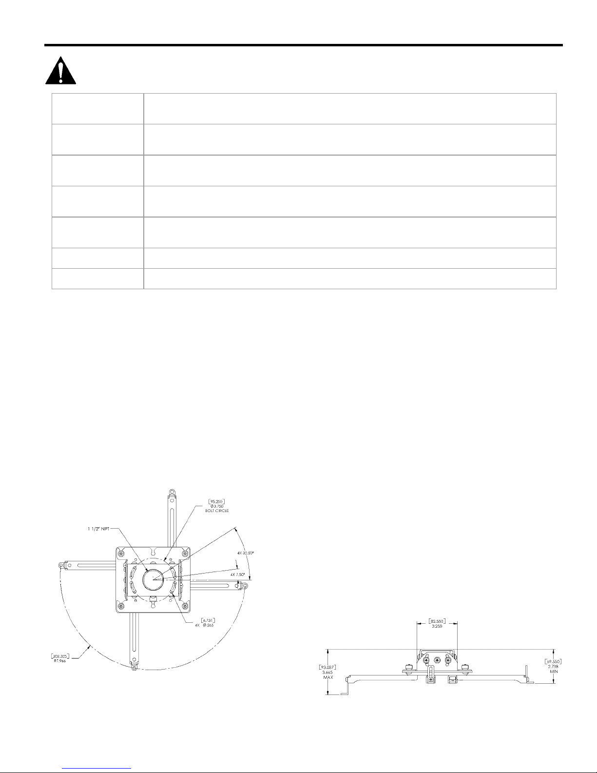
DIMENSIONS
SHIPPING CONTENTS
BEFORE PROCEEDING: Unpack the carton. Verify
contents listed in:
• Error! Reference source not found. and Figure
1. SLB-U Assembly on page 4.
• Table 7 and Figure 15. All-Points™ Security
System Kit on page 11.
Read installation instructions completely. If you are
missing any of the listed components, contact Customer
Service at: 1-800/582-6480.
Top View
2
Front View
Page 3

Installation Instructions SLB-U
CONTENTS
TOOLS REQUIRED FOR INSTALLATION..................2
DIMENSIONS ..................................................................2
SHIPPING CONTENTS...................................................2
MOUNTING HARDWARE.............................................3
PARTS ..............................................................................4
INSTALLATION INSTRUCTIONS................................5
Measuring the Mounting Hole Dimensions On the
Projector............................................................................5
Adjusting the Legs on SLB-U...........................................6
Aligning the SLB-U (as shipped) on a Projector with
4 Mounting Holes..........................................................6
Aligning the SLB-U (minus 1 adjustable leg) on a
Projector with 3 Mounting Holes ..................................7
Aligning the SLB-U (using horizontal slot) on a
Projector with 3 Mounting Holes ..................................8
Aligning the SLB-U on a Projector using direct
mounting option ............................................................9
Adjusting Foot Height on SLB-U .....................................10
Positioning the SLB-U on the Projector............................10
ALL-POINTS SECURITY KIT .......................................11
MOUNTING HARDWARE
Table 1. Mounting Hardware
ITEM DESCRIPTION QTY NOTES
10 SLB-U Assembly 1
20 M6 x 12mm Phillips
Pan Head Screw
30 M5 x 12mm Phillips
Pan Head Screw
40 M4 x 12mm Phillips
Pan Head Screw
50 M3 x 10mm Phillips
Pan Head Screw
60 M6 Flat Washer
Used with screws
(20) and (30)
70 M4 Flat Washer
Used with screws
(40) and (50)
80 10-24 Thumb Nuts 4
4
Used with M6
Flat Washers
4
4
4
4
4
(60)
Used with M4
Flat Washers
(70)
Used to attach
SLB-U to RPA
Table 2. Direct Mounting (without foot brackets)
ITEM DESCRIPTION QTY NOTES
90 M6 x 25mm Phillips
Pan Head Screw
100 M5 x 25mm Phillips
Pan Head Screw
110 M4 x 25mm Phillips
Pan Head Screw
120 M3 x 25mm Phillips
Pan Head Screw
4
4
4
4
Used with M6
Flat Washers
(60)
Used with M4
Flat Washers
(70)
3
Page 4
Installation Instructions SLB-U
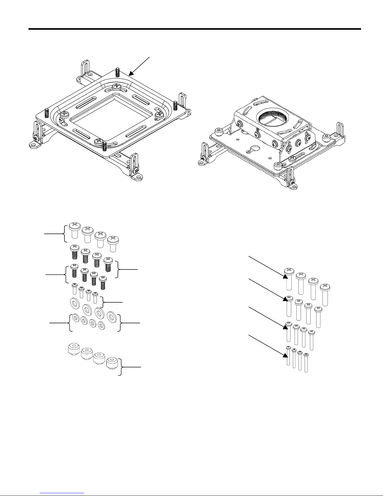
PARTS
10
Figure 1. SLB-U Assembly
Figure 2. SLB to RPA
20
40
50
70
Figure 3. Mounting Hardware Kit
90
30
100
110
60
80
120
Figure 4. Direct Mounting (without foot brackets)
4
Page 5

Installation Instructions SLB-U
INSTALLATION INSTRUCTIONS
STEP 1 (Optional)
Measuring the Mounting Hole
Dimensions On the Projector
To minimize error, perform the following steps to
measure the approximate width and length between the
mounting holes on your projector.
1. Determine the width and length between the
mounting holes on your projector. If necessary, use a
tape measure.
a. If your projector is equipped with four mounting
holes, measure the width and length between the
mounting holes (see Figure 5.
b. If your projector is equipped with three mounting
holes, measure the width and length between the
mounting holes (see Figure 6).
2. Record the dimensions taken in step 1 for later use in
the next procedure.
Figure 5. Measure Width and Length Between
Mounting Holes in 4-Hole Projector (Example)
OR
Figure 6. Measure Width and Length Between
Mounting Holes in 3-Hole Projector (Example)
5
Page 6

Installation Instructions SLB-U
STEP 2
4. Attach the SLB-U to the projector, as follows:
Adjusting the Legs on SLB-U
The mounting holes on projectors are supplied in a
variety of different patterns. There is no standard
mounting-hole configuration pattern for projectors.
The SLB-U will generally accommodate the mountinghole pattern on most projectors, providing that the SLB-U
adjustable legs can be configured to match the mounting
holes on your projector.
Due to the number of configurations that the SLB-U can
accommodate, this instruction guide only provides
a. Select the screw size that fits the threaded inserts
on your projector (see Table 3).
b. Select the washer that fits the selected screw.
c. Attach the SLB-U to the projector using the
selected fasteners in accordance with Table 3. Do
not tighten the screws at this time.
5. Attach the SLB-U to RPA (see Figure 2).
Table 3. SLB-U Mounting Hardware
guidance for the three most commonly used SLB-U
configurations on projectors. Select the applicable
procedure to mount the SLB-U on your projector:
• Step 2 (Option A). Align the SLB-U on a projector
with 4 mounting holes.
• Step 2 (Option B). Align the SLB-U on a projector
with 3 mounting holes.
• Step 2 (Option C). Align the SLB-U on a projector
using horizontal slot and 3 mounting holes.
• Step 2 (Option D). Align the SLB-U on a projector
using direct mounting option.
ITEM DESCRIPTION QTY NOTES
20 M6 X 12MM SCREW 4
30 M5 X 12MM SCREW 4
40 M4 X 12MM SCREW 4
50 M3 X 10MM SCREW 4
60 M6 FLAT WASHER 4
70 M4 FLAT WASHER 4
10-24
80
THUMB NUT 4
USE ITEM 60 WITH
ITEMS
USE ITEM 70 WITH
ITEMS
USE TO ATTACH
SLB-U TO RPA
20 AND 30
40 AND 50
STEP 2 (OPTION A)
Aligning the SLB-U (as shipped) on a Projector
with 4 Mounting Holes
Align the SLB-U on the projector, as follows:
1. Locate the four mounting holes on your projector.
2. Using a Phillips screwdriver, loosen the four screws.
Do not remove the screws.
NOTE: If necessary, use the measurements that you
recorded when you completed Step 1,
“Measuring the Mounting Holes On Projector” to
help align the adjustable legs with the mountinghole pattern on the projector.
3. Align the SLB-U on projector, as follows:
a. Place the SLB-U (10) on your projector.
b. Adjust the legs on the SLB-U (10) as needed.
Align the adjustable legs on the SLB-U with
mounting holes on your projector.
10
Loosen screws. Adjust legs
on SLB-U, as needed. Align
legs on SLB-U with
mounting holes on projector.
Figure 7. Align the SLB-U on 4-Hole Projector
6
Page 7

Installation Instructions SLB-U
t
STEP 2 (OPTION B)
Aligning the SLB-U (minus 1 adjustable leg) on a
Projector with 3 Mounting Holes
Align the SLB-U on the projector, as follows:
Loosen screws. Adjust legs
on SLB-U, as needed. Align
legs on SLB-U with
mounting holes on projector.
1. Locate the three mounting holes on your projector.
2. Using a Phillips screwdriver, remove the screw, hex
nut, and one adjustable leg from the SLB-U (10) (see
Figure 8).
NOTE: Keep unused adjustable leg and attaching
hardware in a safe for future use.
3. Loosen the three remaining screws. Do not remove
the screws.
NOTE: If necessary, use the measurements that you
recorded when you completed Step 1,
“Measuring the Mounting Holes On Projector” to
help align the adjustable legs with the mountinghole pattern on the projector.
4. Align the SLB-U on the projector, as follows:
a. Place the SLB-U (10) on your projector.
b. Adjust the legs on the SLB-U (10) as needed.
Align the adjustable feet on the SLB-U with
mounting holes on your projector.
5. Attach the SLB-U to the projector, as follows:
10
Remove screw and
hex nut to remove
th
the 4
leg from the
SLB-U.
Screw
4th leg
Hex nu
Figure 8. Align the SLB-U on 3-Hole Projector
a. Select the screw size that fits the threaded inserts
on your projector (see Table 4).
b. Select the washer that fits the selected screw.
c. Attach the SLB-U to the projector using the
selected fasteners in accordance with Table 4. Do
not tighten the screws at this time.
Table 4. SLB-U Mounting Hardware
ITEM DESCRIPTION QTY NOTES
20 M6 X 12MM SCREW 4
30 M5 X 12MM SCREW 4
40 M4 X 12MM SCREW 4
50 M3 X 10MM SCREW 4
60 M6 FLAT WASHER 4
70 M4 FLAT WASHER 4
10-24
80
THUMB NUT
USE ITEM 60 WITH
ITEMS
USE ITEM 70 WITH
ITEMS
4
20 AND 30
40 AND 50
USE TO ATTACH
SLB-U TO RPA
6. Attach the SLB-U to RPA (see Figure 2).
7
Page 8

Installation Instructions SLB-U
STEP 2 (OPTION C)
Aligning the SLB-U (using horizontal slot) on a
Projector with 3 Mounting Holes
Align the SLB-U on the projector, as follows:
1. Locate the three mounting holes on your projector.
7. Attach the SLB-U to RPA (see Figure 2).
Loosen screws. Adjust legs
on SLB-U, as needed. Align
legs on SLB-U with
mounting holes on projector.
2. Using a Phillips screwdriver, remove two screws, hex
nuts, and two adjustable legs from the SLB-U (10)
(see Figure 9).
NOTE: Keep unused adjustable leg and attaching
hardware in a safe for future use.
3. Select the applicable horizontal slot to install the
adjustable leg (see Figure 9 and Figure 10).
4. Loosen the three remaining head screws. Do not
Screw
10
remove the screws.
NOTE: If necessary, use the measurements that you
Hex nut
recorded when you completed Step 1,
“Measuring the Mounting Holes On Projector” to
help align the adjustable legs with the mounting-
Install adjustable leg
in horizontal slot.
hole pattern on the projector.
Figure 9. Align the SLB-U on 3-Hole Projector Using
5. Align the SLB-U on the projector, as follows:
a. Place the SLB-U (10) on your projector.
Horizontal Slots
b. Adjust the legs on the SLB-U (10) as needed.
Align the adjustable feet on the SLB-U with
mounting holes on your projector.
6. Attach the SLB-U to the projector, as follows:
c. Select the screw size that fits the threaded inserts
on your projector (see Table 5).
Screw
OR
Loosen screws. Adjust legs
on SLB-U, as needed. Align
legs on SLB-U with
mounting holes on projector.
d. Select the washer that fits the selected screw.
e. Attach the SLB-U to the projector using the
selected fasteners in accordance with Table 5. Do
not tighten the screws at this time.
Table 5. SLB-U Mounting Hardware
ITEM DESCRIPTION QTY NOTES
20 M6 X 12MM SCREW 4
30 M5 X 12MM SCREW 4
40 M4 X 12MM SCREW 4
50 M3 X 10MM SCREW 4
60 M6 FLAT WASHER 4
70 M4 FLAT WASHER 4
10-24
80
8
THUMB NUT 4
USE ITEM 60 WITH
ITEMS
20 AND 30
USE ITEM 70 WITH
ITEMS
40 AND 50
USE TO ATTACH
SLB-U TO RPA
Install adjustable leg
in horizontal slot.
Hex nut
Figure 10. Align the SLB-U on 3-Hole Projector
Using Horizontal Slots
Page 9

Installation Instructions SLB-U
STEP 2 (OPTION D)
Aligning the SLB-U on a Projector using direct
5. Attach the SLB-U to RPA (see Figure 2).
mounting option
Align the SLB-U on the projector, as follows:
1. Locate the mounting holes on your projector.
2. Using a Phillips screwdriver, remove foot bracket
screws and foot brackets (see Figure 11).
NOTE: Keep unused adjustable foot brackets and
attaching hardware in a safe for future use.
3. Align the SLB-U on the projector, as follows:
a. Place the SLB-U (10) on your projector.
b. Adjust the legs on the SLB-U (10) as needed.
Align the legs on the SLB-U with mounting holes
on your projector.
4. Attach the SLB-U to the projector, as follows:
a. Select the screw size that fits the threaded inserts
on your projector (see Table 6).
b. Select the washer that fits the selected screw.
c. Attach the SLB-U to the projector using the
selected fasteners in accordance with Table 6 (see
Figure 12). Do not tighten the screws at this time.
Table 6. SLB-U Mounting Hardware
ITEM DESCRIPTION QTY NOTES
90 M6 x 25mm Phillips
Pan Head Screw
100
M5 X 25MM PHILLIPS
PAN HEAD SCREW
110 M4 x 25mm Phillips
Pan Head Screw
4
Used with M6 Flat
Washers (60)
4
4
Used with M4 Flat
Washers (70)
Figure 11. Remove Feet
Swing legs inside for
close hole pattern
Figure 12. Install the SLB-U on Projector
120
M3 X 25MM PHILLIPS
PAN HEAD SCREW
4
9
Page 10

Installation Instructions SLB-U
STEP 3
Adjusting Foot Height on SLB-U
Adjust the feet on the SLB-U for height, as follows:
NOTE: Foot height is adjusted for a variety of reasons,
which includes, but is not limited to, ventilation,
uneven projector surface, and to level the RPA
mounting plate.
1. Visually check the height of the RPA mounting plate
on the SLB-U. Review the reasons for foot height
adjustment, noted above.
2. Loosen the screw and adjust the foot that is attached
to the adjustable leg on the SLB-U (see Figure 13).
3. Adjust foot height as needed. If necessary, use a level
to verify that the RPA mounting plate is level.
4. Tighten the screw.
5. Repeat procedure for each foot as needed until the
feet on the SLB-U are adjusted to your satisfaction.
Level the
RPA
Mounting
Plate
Loosen the screw.
Adjust foot height.
Tighten the screw
Figure 13. Adjust Leg Height on SLB-U
STEP 4
Positioning the SLB-U on the
Projector
Position the on the SLB-U on your projector, as follows:
NOTE: When positioning the SLB-U on your projector,
take into consideration the weight of the
projector and its center of gravity.
1. Slide the SLB-U into the position that you want on
your projector.
WARNING
Failure to tighten the screws after positioning the
SLB-U on your projector could result in damage
to your projector.
2. Tighten the screws shown in Figure 14.
NOTE: For further instructions, see the applicable
RPA and/or Smart-lift™ instruction manuals.
Position SLB-U on the
projector. Tighten the
screws.
Figure 14. Position the SLB-U and
Tighten the Screws
10
Page 11

Installation Instructions SLB-U
STEP 5 (Optional)
ALL-POINTS SECURITY KIT
For All-Points™ Security, use the security hardware package inside the All-Points™ Security Kit. Follow the
instructions for attaching the bracket to the projector using either standard hardware or security hardware.
NOTE: You must retain the Security Allen Wrench if security screws are installed. Do not discard this wrench or
leave it where unauthorized persons have access to your Security Allen Wrench.
Table 7 and Figure 15. All-Points™ Security System Kit shows the All-Points™ Security Kit parts.
Table 7. All-Points™ Security Kit Parts
ITEM DESCRIPTION QTY NOTES
130 M3 x 10mm Button Head Security Screw 4
140 M4 x 12mm Button Head Security Screw 4
150 M5 x 12mm Button Head Security Screw 4
160 M6 x 12mm Button Head Security Screw 4
170 10-24 x ¼” Flat Head Undercut Security Screw 2 RPA to SLB-U
SLB-U
Mounting
Hardware
180 3/32” Security Hex Key 1
190 5/32” Security Hex Key 1
200 5/16-18 Security Set Screw 1
210 10-24 x 3/8” Button Head Security Screw 4
220 1/4-20 x 1/2” Button Head Security Screw 4
230 10-24 x 1/4” Button Head Security Screw 4
130
140
150
160
220
230
Special Tools
RPA
SLB-U Leg
Attachment
SLB-U Feet
Attachment
190
180
210
170
200
Figure 15. All-Points™ Security System Kit
11
 Loading...