

Page 1
I N S T R U C T I O N M A N U A L
russ
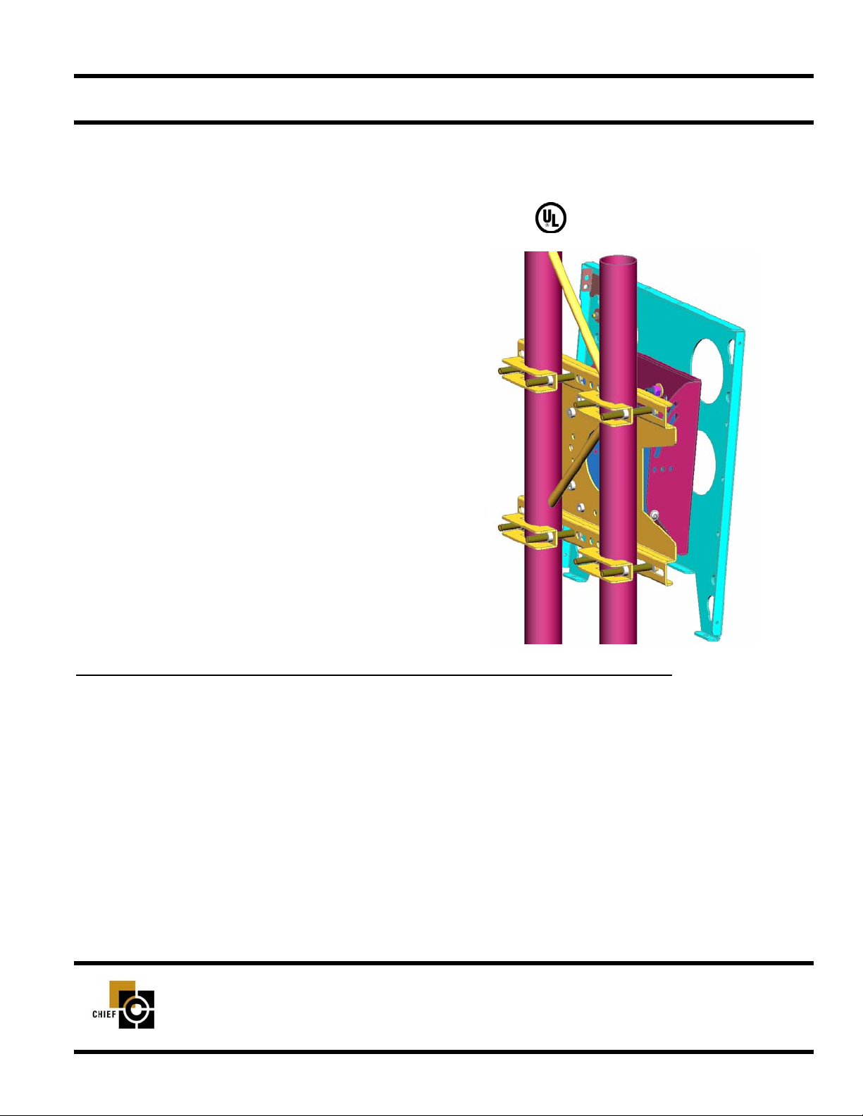
Pitch-Adjustable (TPP) Mount
The Truss Pitch-Adjustable (TPP) mount is a perfect
solution exhibit, retail and digital signage applications.
The mount is quick, easy and versatile.
The TPP accommodates a large range of truss dimensions (up to 14” O.D.), includes security options and provides flexible feature to achieve a custom installation
installation. The exclusive Q-Latch™ Mounting System
secures the LArge Flat Panel Display with a lockable
latch to confirm mount stability and integrated security
allows the display to be locked to the mount by adding a
padlock.
Your display can be mounted portrait or landscape and
four pitch adjustments, up or down, are available as preset, locking positions (0, 5, 10 or 15 degrees).
BEFORE YOU BEGIN
• WARNING: TO PREVENT PERSONAL INJURY, THOROUGHLY STUDY ALL INSTRUCTIONS AND ILLUS-
TRATIONS BEFORE YOU BEGIN TO INSTALL THE UNIT. PAY PARTICULAR ATTENTION TO THE “IMPORTANT WARNINGS AND CAUTIONS” ON PAGE 1.
• CAUTION: To prevent damage to the mount, which could affect or void the Factory warranty, thoroughly
study all instructions and illustrations before you begin to install the unit. Pay particular attention to the
“IMPORTANT WARNINGS AND CAUTIONS” on Page 1.
• The maximum weight to be installed on the TPP is 150 pounds (68.04 Kg).
• If you have any questions about this assembly, contact Chief Manufacturing at 1-800-582-6480 or 952-582-6480.
PART NO. 8804 -000010 (Rev. B)
©2003 Chief Manufacturing
www.chiefmfg.com
Printed in USA 05-04
LOGO
CHIEF MANUFACTURING INC.
1-800-582-6480 952-894-6280 FAX 952-894-6918
8401 EAGLE CREEK PARKWAY
SAVAGE, MINNESOTA 55378 USA
Page 2

Instruction Manual TPP
IMPORTANT WARNINGS AND CAUTIONS!
• WARNING: A WARNING alerts you to the possibility of serious injury or death if you do not follow the instructions.
• CAUTION: A CAUTION alerts you to the possibility of damage or destruction of equipment if you do not follow the corre-
sponding instructions.
• WARNING: Improper installation can result in serious personal injury! Make sure that the structural members can
support a redundant weight factor five times
can not support this weight, reinforce the structural members before installing the mount.
• WARNING: The installer is responsible for verifying that the structure to which the TPP is anchored will safely support the combined load of all attached components or other equipment.
• WARNING: The weight of the display must not exceed 150 lbs. (68.04 kg), the maximum load capacity of the TPP.
• WARNING: Be aware during the installation that there are no pinch points for people and for electrical wiring.
• WARNING: Be aware of the potential for personal injury or damage to the mount if it is not adequately mounted.
• CAUTION: Check the unit for shipping damage before you begin the installation.
the total weight of the equipment. If the structural members
• CAUTION: Changes or modifications not approved by Chief Manufacturing could void user’s warranty.
TOOLS REQUIRED FOR INSTALLATION
• Socket set with extension
• Open wrenches
NOTE: Other tools may be required depending on the
method of installing the lift in the ceiling.
CONTENTS
PARTS........................................................................ 2
INSPECT THE MOUNT BEFORE INSTALLING ....... 3
TPP INSTALLATION ................................................. 3
Assembly ................................................................... 3
Mount the Display ....................................................... 5
Tilt Adjustment ........................................................... 5
Remove the Display ................................................... 6
1
Page 3
Instruction Manual TPP
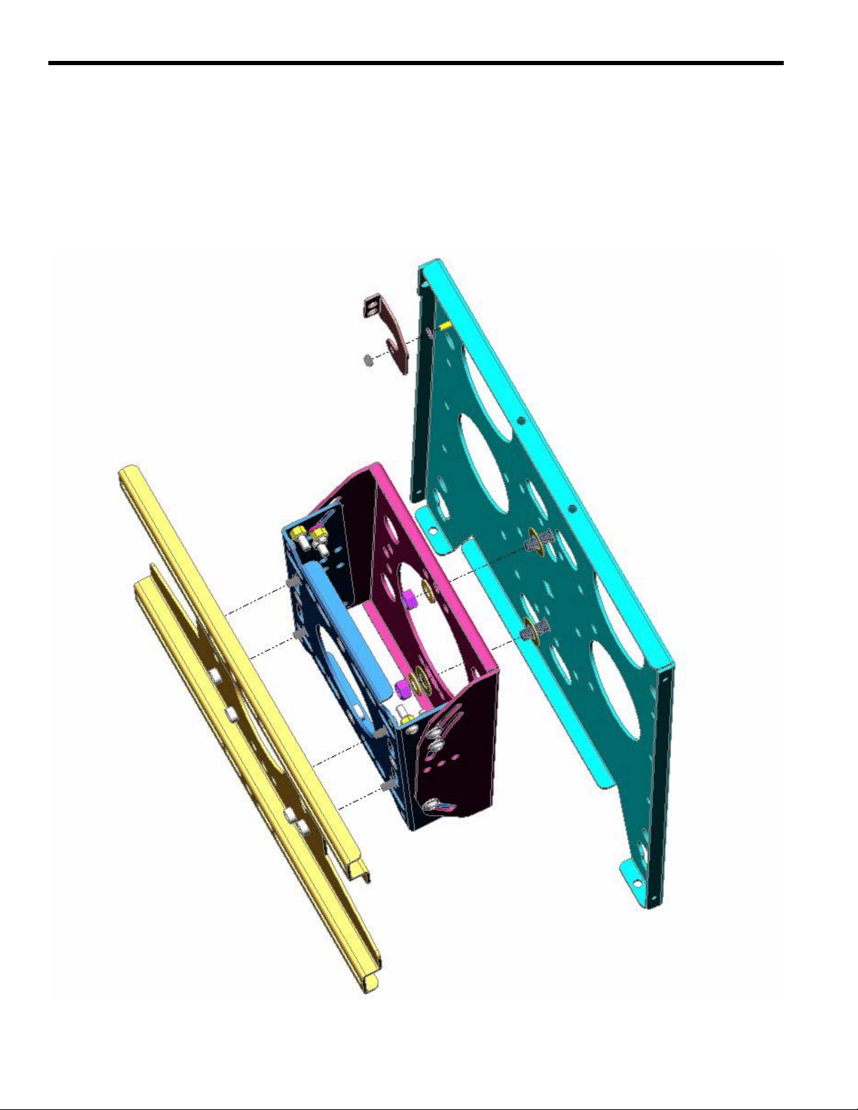
(1) PLATE, back (1) SCREW, pan head, 10-24
(1) PLATE, assembly, pitch-adjustable (4) SCREW, cap, hex head, 5/16-18 X 1/2”
(1) PLATE, face (2) NUT, Stover locknut, 3/8-16
(1) FLAG, latching (1) SPACER, Nylon, .38 X .194 X .032”
(1) NUT, Nylock, 10-24 (2) WASHER, flat, 3/8”
(3) WASHER, VHMW
PARTS
2
Page 4

Instruction Manual TPP
INSPECT THE MOUNT
BEFORE INSTALLING
IMPORTANT: Before installing the mount, make sure it has
not been damaged during shipping.
1. Carefully inspect the mount for shipping damag e . If an y dam age is apparent, call your carrier claims agent and do not continue with the installation of the mount the until carrier has
reviewed the damage.
TPP INSTALLATION
Assembly
1. Install the Nylon spacer on the stud in the corner of the face
plate (see Figure 1).
2. Install the latching flag over the Nylon spacer.
3. Secure the latching flag to the face plate using the 1/4-20
Nylock nut loose enough to move but tight enough to remain in
place when raised.
Latching Flag
10-24 Nut
stud
Nylon Spacer
Figure 1. Install Flag
WARNING: It is the responsibility of the installer to verify that
the structure to which the TPP is anchored will
safety support the combined load of all attached
components and equipment.
4. Securely anchor the back plate to the framework using Chief
TPK accessory clamps or equivalent rated fasteners for the
required load (see Figure 2).
5. Install the pitch-adjustable plate on the back plate and secure
using four 5/16-18 X 1/2” hex head cap screws (see Figure 3).
5/16-18 X 1/2” Hex Head Cap Screws
Figure 2. Anchor Back Plate
Figure 3. Pitch-Adjustable Plate to Back Plate
3
Page 5

Instruction Manual TPP
6. Install the face plate in the desired position (see Figure 4, Figure 5, Figure 6 and Figure 7) on the pitch-adjustable plate and
secure using two 3/8-16 Nylock nuts and washers in any
matching set of radial holes slotted to allow slight roll adjustment.
Figure 4. Vertical Tilt Shown without Back Plate for Clarity
3/8-16 Nylock Nuts and Washers
Figure 6. Vertical Truss Shown with Back Plate
4
Figure 5. Horizontal Tilt Shown without Back Plate for Clarity
Figure 7. Horizontal Truss Shown with Back Plate
Page 6

Instruction Manual TPP
Mount the Display
1. Attach included PSB brackets to your display using the instruc-
tions included with the PSB package.
2. Make sure no power is supplied to the display and the flag is in
the down position before attempting to mount the display.
3. Using two people, slide the display down over the four slots in
the face plate of the TPP. Make sure all four Quick Latches (QLatches) of the display engage all four slots in the TPP.
WARNING: Make sure the flag securing the display is com-
pletely raised at all times except when removing or
installing the display. The flag must be all the way
up when installing/removing cables.
4. With the Q-Latches of the display fully engaged in the slots of
Q-Latch Engaged
the TPP, secure the display on the TPP by raising the flag all
the way up to the locked position (see Figure 8). If the flag
does not fully engage, remove the display and make sure the
brackets are corr ectly installed.
Figure 8. Engage Q-Latch
NOTE: A security lock may be installed through the hole in the
flag for additional security.
Tilt Adjustment Screw
(One Each Side)
Tilt Adjustment
WARNING: Watch for pinch points. Do not put your fingers
between movable parts.
1. Loosen tilt adjustment screws, adjust to desired tilt, and tighten
tilt adjustment screws if necessary (see Figure 9).
2. Loosen tilt adjustment screws, adjust to desired tilt, and tighten
tilt adjustment screws if necessary (see Figure 10, Figure 11,
and Figure 12).
0 Degree
(Outside Hole)
5 Degree
(Tilt Hole)
Figure 9. Tilt Adjustment Screw Location
10 Degree
(Tilt Hole)
Figure 10. 0 Degree Tilt
Figure 11. 5 Degree Tilt
Figure 12. 10 Degree Tilt
5
Page 7

Instruction Manual TPP
Remove the Display
WARNING: Make sure the flag securing the display is com-
pletely raised at all times except when removing or
installing the display. The flag must be all the way
up when installing/removing cables.
WARNING: Watch for pinch points. Do not put your fingers
between movable parts.
1. Unlock the display from the TPP by lowering the flag all the
way down to the unlocked position.
4. Using two people, slide the display up and out of the TPP.
6
 Loading...