

INSTALLATION INSTRUCTIONS
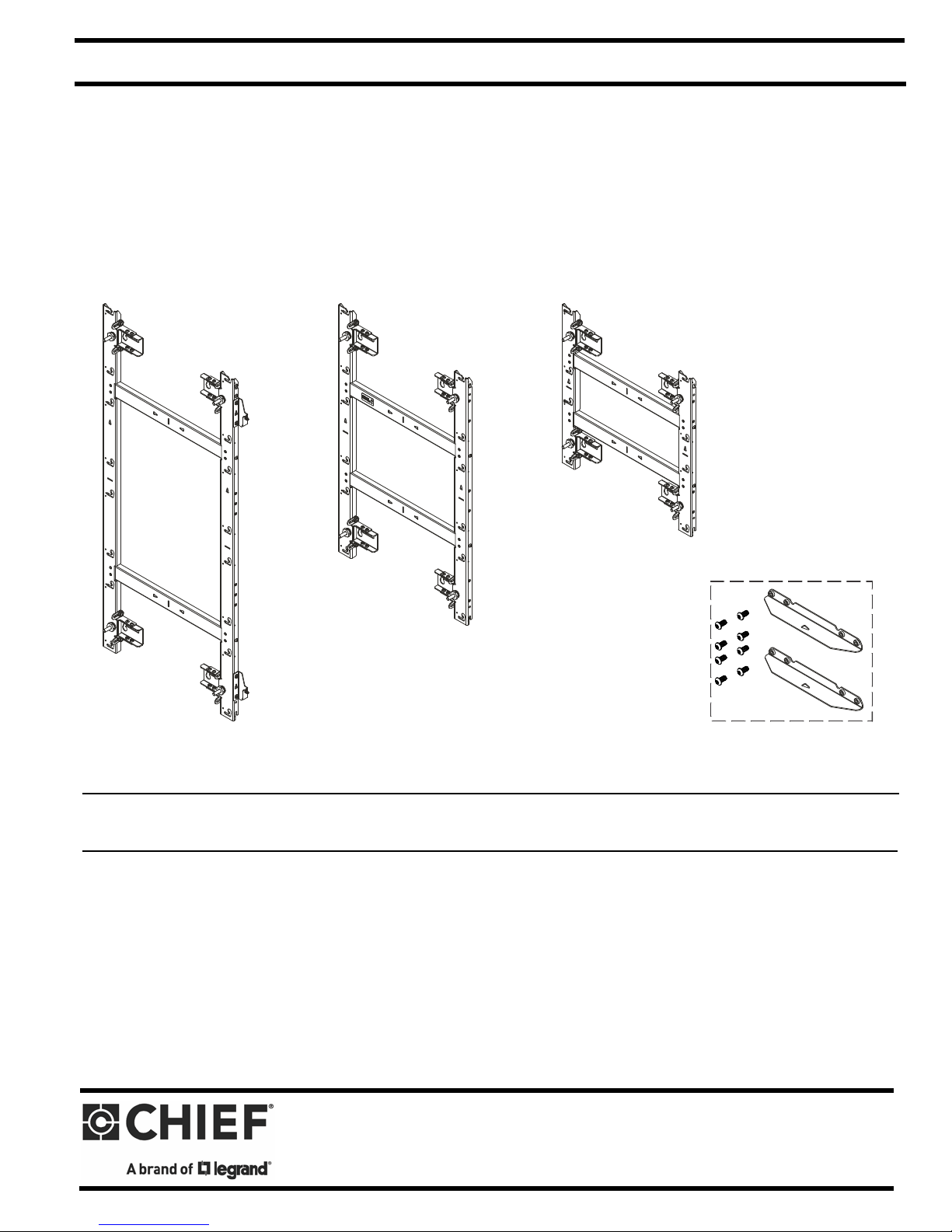
TIL1X2AA
TIL1X3AA
TIL1X4AA
TILVABAA
Accessory
AA Series LED Wall Mounts / Accessory
Spanish Product Description
German Product Description
Portuguese Product Description
Italian Product Description
Dutch Product Description
French Product Description
TILVABAA
TIL1X2AA / TIL1X3AA / TIL1X4AA / TILVABAA Installation Instructions
DISCLAIMER
Legrand | AV and its affiliated corporations and subsidiaries
(collectively “Legrand | AV”), intend to make this manual
accurate and complete. However, Legrand | AV makes no claim
that the information contained herein covers all details,
conditions or variations, nor does it provide for every possible
contingency in connection with the installation or use of this
product. The information contained in this document is subject
to change without notice or obligation of any kind. Legrand | AV
makes no representation of warranty, expressed or implied,
regarding the information contained herein. Legrand | AV
assumes no responsibility for accuracy, completeness or
sufficiency of the information contained in this document.
DEFINITIONS
MOUNTING SYSTEM: A MOUNTING SYSTEM is the
primary Chief product to which an accessory and/or component
is attached.
ACCESSORY: AN ACCESSORY is the secondary Chief
product which is attached to a primary Chief product, and may
have a component attached or setting on it.
WARNING: The TIL1X2AA / TIL1X3AA / TIL1X4AA LED
wall mounts are designed for use with the Absen Acclaim
Series LED only. Exceeding the weight capacity (listed) can
result in serious personal injury or damage to equipment!
• TIL1X2AA: 40 lbs (18.1 kg) - 20 lbs (9.1 kg) per
module;
• TIL1X3AA: 60 lbs (27.2 kg) - 20 lbs (9.1 kg) per
module;
• TIL1X4AA: 80 lbs (36.3 kg) - 20 lbs (9.1 kg) per
module.
WARNING: Use this mounting system only for its intended
use as described in these instructions. Do not use
attachments not recommended by the manufacturer.
WARNING: Never operate this mounting system if it is
damaged. Return the mounting system to a service center for
examination and repair.
WARNING: Do not use this mounting system outdoors.
COMPONENT: A COMPONENT is an audiovisual item
designed to be attached or resting on an accessory or mounting
system such as a video camera, CPU, screen, display,
projector, etc.
WARNING: A WARNING alerts you to the possibility of
serious injury or death if you do not follow the instructions.
CAUTION: A CAUTION alerts you to the possibility of
damage or destruction of equipment if you do not follow the
corresponding instructions.
IMPORTANT SAFETY INSTRUCTIONS
WARNING: Failure to read, thoroughly understand, and
follow all instructions can result in serious personal injury,
damage to equipment, or voiding of factory warranty! It is the
installer’s responsibility to make sure all mounting systems
are properly assembled and installed using the instructions
provided.
WARNING: Failure to provide adequate structural strength
for this mounting system can result in serious personal injury
or damage to equipment! It is the installer’s responsibility to
make sure the structure to which this mounting system is
attached can support five times the combined weight of all
equipment. Reinforce the structure as required before
installing the mounting system. The wall to which the
mounting system / accessory is being attached may have a
maximum drywall thickness of 5/8” (1.6cm). Do not install
drywall anchors into the seam between drywall pieces.
IMPORTANT ! : The TIL1X2AA / TIL1X3AA /TIL1X4AA
(Absen Acclaim Series) LED wall mounts are designed to be
mounted to:
• a bare 8" concrete or 8"x8"x16" concrete block wall; or
• a 3/4" thickness plywood-backed, 2" x 4" wood studs
(16" on center minimum) wall with a maximum drywall
thickness of 5/8"; or
• a 3/4" thickness plywood-backed, steel stud wall
covered with drywall having a maximum thickness of
5/8".
--SAVE THESE INSTRUCTIONS--
2
TIL1X2AA / TIL1X3AA / TIL1X4AA / TILVABAA Installation Instructions
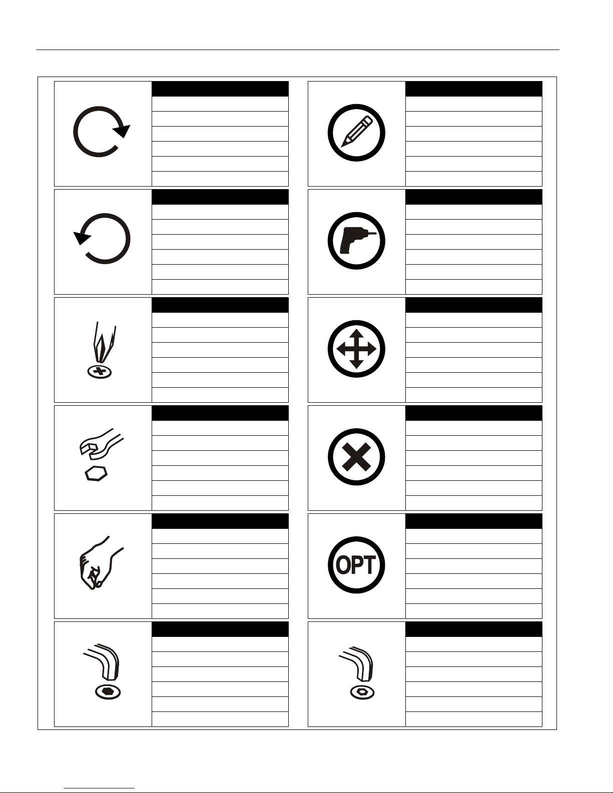
Tighten Fastener
Apretar elemento de fijación
Befestigungsteil festziehen
Apertar fixador
Serrare il fissaggio
Bevestiging vastdraaien
Serrez les fixations
Loosen Fastener
Aflojar elemento de fijación
Befestigungsteil lösen
Desapertar fixador
Allentare il fissaggio
Bevestiging losdraaien
Desserrez les fixations
Phillips Screwdriver
Destornillador Phillips
Kreuzschlitzschraubendreher
Chave de fendas Phillips
Cacciavite a stella
Kruiskopschroevendraaier
Tournevis à pointe cruciforme
Open-Ended Wrench
Llave de boca
Gabelschlüssel
Chave de bocas
Chiave a punte aperte
Steeksleutel
Clé à fourche
By Hand
A mano
Von Hand
Com a mão
A mano
Met de hand
À la main
Hex-Head Wrench
Llave de cabeza hexagonal
Sechskantschlüssel
Chave de cabeça sextavada
Chiave esagonale
Zeskantsleutel
Clé à tête hexagonale
Pencil Mark
Marcar con lápiz
Stiftmarkierung
Marcar com lápis
Segno a matita
Potloodmerkteken
Marquage au crayon
Drill Hole
Perforar
Bohrloch
Fazer furo
Praticare un foro
Gat boren
Percez un trou
Adjust
Ajustar
Einstellen
Ajustar
Regolare
Afstellen
Ajuster
Remove
Quitar
Entfernen
Remover
Rimuovere
Verwijderen
Retirez
Optional
Opcional
Optional
Opcional
Opzionale
Optie
En option
Security Wrench
Llave de seguridad
Sicherheitsschlüssel
Chave de segurança
Chiave di sicurezza
Veiligheidssleutel
Clé de sécurité
LEGEND
3
Installation Instructions TIL1X2AA / TIL1X3AA / TIL1X4AA / TILVABAA
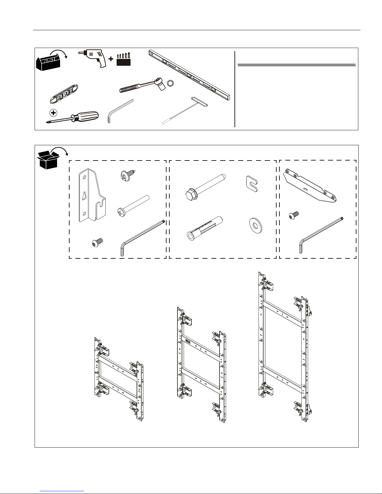
Hardware Required - not included
(for installation into steel stud walls)
1. Chief brand FCAT1 Toggler Kit; OR
2. Hardware for installation to steel stud wall:
• 1/4-20 Toggler Snaptoggle BB (Qty 4)
• 1/4-20 x 2-1/2" hex head bolt (Qty 4)
• 1/4" washer (Qty 4)
7/32"
#2
Level
[4+ ft. long]
[Small level]
3/8"
1/2"
T-Handle
drive with
1" socket
1/2"
5/32"
(included)
Horizontal Connector Kit
F (4)
5/16 x 2-1/2"
G (4)
UX10x60R
H (2)
[Installation
Connector Kit
K (2)
[Vertical connector]
L (8)
1/4-20 x 1/2"
N (1)
[TIL1X2AA]
P (1)
[TIL1X3AA]
Q (1)
[TIL1X4AA]
TILVABAA Vertical
OR
OR
Mounting Hardware Kit
washer]
J (4)
5/16"
A (2)
[Horizontal
connector]
B (8)
1/4-20 x 1/2"
C (6)
08-32 x 1/2"
D (8)
10-24 x 1-1/2"
E (1)
5/32"
M (1)
5/32"
TOOLS REQUIRED FOR INSTALLATION
PARTS
4
Installation Instructions TIL1X2AA / TIL1X3AA / TIL1X4AA / TILVABAA
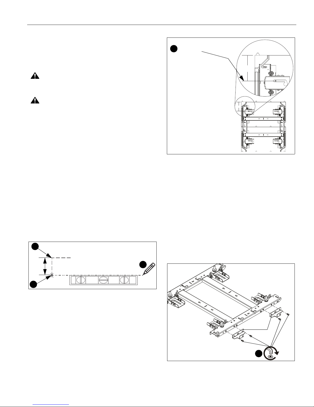
Location for top left corner of LED wall
1
2
5"
3
5”
5”
[TIL1X2AA shown as example]
3
Mounting slot
center line
2
(B) x 4
(A)
[TIL1X2AA shown as example]
INSTALLATION
Preinstallation
IMPORTANT ! : Reference the LED module installation
manual for specific instructions regarding care, handling,
cabling and installation of the LED modules.
CAUTION: Handle the LED modules with care, being
careful to not impact or drop the LED module.
CAUTION: There is a magnetic surface on the front of the
LED module. To prevent damage ensure that no metallic
object is pulled onto the LED module.
NOTE: When planning the installation, remember the
requirement to run power and signal to the video wall.
Determining Installation Site
IMPORTANT ! :
the center line of the mounting slots. (See Figure 1)
1. Determine location for the top left corner of the LED wall.
(See Figure 1)
2. Make a mark 5" below the planned top left corner of the LED
wall. (See Figure 1)
3. Using a level, mark a horizontal line across width of LED
wall from the mark made in Step 2.
NOTE:
This line will indicate the center line of the mounting slots
for the top mount(s) in the LED wall. (See Figure 1) and
(See Figure 2)
The top of the LED housing is 5" above
Figure 1
Figure 2
(OPTIONAL) Attaching Horizontal Connectors
NOTE: The horizontal connectors (A) must be attached if the
LED wall will be wider than one mount.
NOTE: It will be easier to attach the connectors before
installing the mount to the wall. However, the
connectors may still be attached after the wall mount is
already on the wall.
1. Lay mount on floor and place horizontal connectors (A)
against right edge of wall mount. (See Figure 3)
2. Attach two connectors to each wall mount using two 1/4-20
x 1/2" button head cap screws (B) per horizontal connector.
(See Figure 3)
Figure 3
5
TIL1X2AA / TIL1X3AA / TIL1X4AA / TILVABAA Installation Instructions
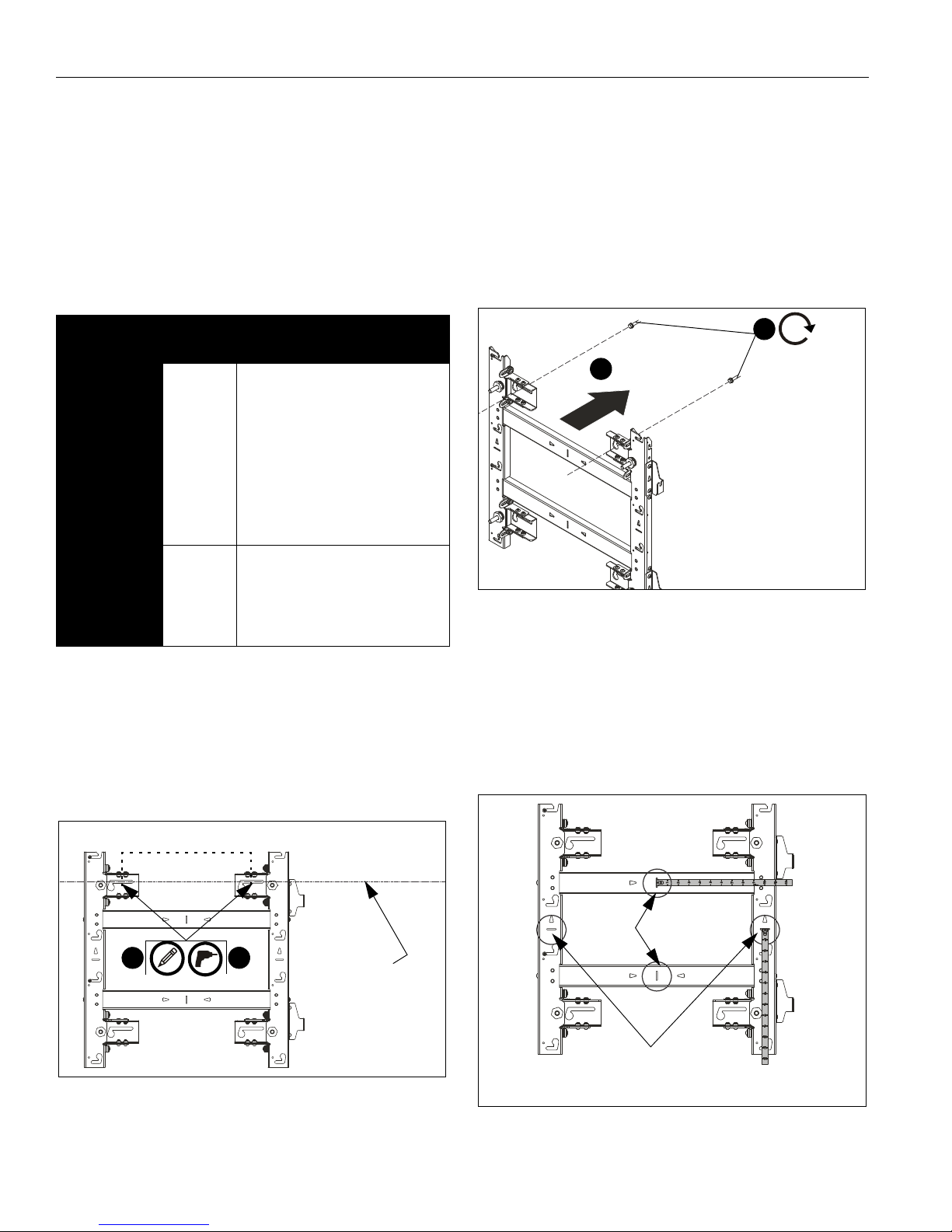
2
14.25 inches
3
Line showing
slots for top
mounts in LED wall
center of mounting
[TIL1X2AA shown as example]
4
5
x 2
[TIL1X2AA shown as example]
Indicates
center line
of the mount
horizontal
Indicates approximate
center line between
two LED modules
Installing First Mount
The TIL1X2AA / TIL1X3AA /TIL1X4AA (Absen Acclaim Series)
LED wall mounts are designed to be mounted to:
• a bare 8" concrete or 8"x8"x16" concrete block wall; or
• a 3/4" thickness plywood-backed, 2" x 4" wood studs
(16" on center minimum) wall with a maximum drywall
thickness of 5/8"; or
•
a 3/4" thickness plywood-backed, steel stud wall
covered with drywall having a maximum thickness of
5/8".
Table 1: Fastener Information
WALL
TYPE
Drywall
attached to
plywoodbacked walls
/Steel studs
Drywall
attached to
plywoodbacked walls
/Wood studs
PILOT
HOLE
1/2"
7/32" x 3"
FASTENERS (see PARTS
drawing)
- 1/4-20 x 2-1/2" hex head lag (not
included)
- 1/4" washer (not included)
- 1/4-20 Toggler Snaptoggle BB
(not included)
- 5/16 x 2-1/2" flanged hex head
lag (F)
- 5/16" washer (J)
- Installation washer (H)
IMPORTANT ! : Refer to Fastener Installation Methods
(located in Appendix at end of Installation Instructions)
for details on installing product into various wall types.
4. Partially install two fasteners into wall, but do NOT
completely tighten to wall. (See Figure 5)
NOTE: Utilizing the two U-shaped installation washers (H)
allows the installer to pre-install the top mounting
fasteners and hang the mount from them utilizing the
mount’s teardrop slots. This allows the weight of the
mount to be held by the mounting bolts and not the
installer during installation.
3/8" x 3" - 5/16 x 2-1/2" flanged hex head
Concrete or
concrete
block
1. Hold furthest left, top wall mount against wall ensuring that
mounting slot is lined up with center line marked on the wall
in Determining Installation Site section. Double-check
with a level. (See Figure 4)
2. Mark mounting holes in two top mounting slots along the
horizontal line marked in Step 3. (See Figure 4)
lag (F)
- 5/16" washer (J)
- Installation washer (H)
- Fischer Anchor UX10x60R (G)
NOTE: The center of the mounting holes are 14.25" apart on-
center. (See Figure 4)
Figure 4
3. Drill two pilot holes (see Table 1 for size) at each location
marked in Step 2 (See Figure 4) and follow fastener
information (appropriate for wall type) located in Table 1.
6
Figure 5
5. Hang wall mount, aligning upper teardrop slots over
fasteners, and adjust side-to-side for proper location. (See
Figure 5)
NOTE: The horizontal slots located along the vertical mount
pieces indicate the approximate center line of the two
LED modules. The vertical slots located along the
horizontal mount pieces indicate the horizontal center
line of the mount. The slots can be used to hold a tape
measure tab while measuring. (See Figure 6)
Figure 6
 Loading...