

Page 1
INSTALLATION INSTRUCTIONS
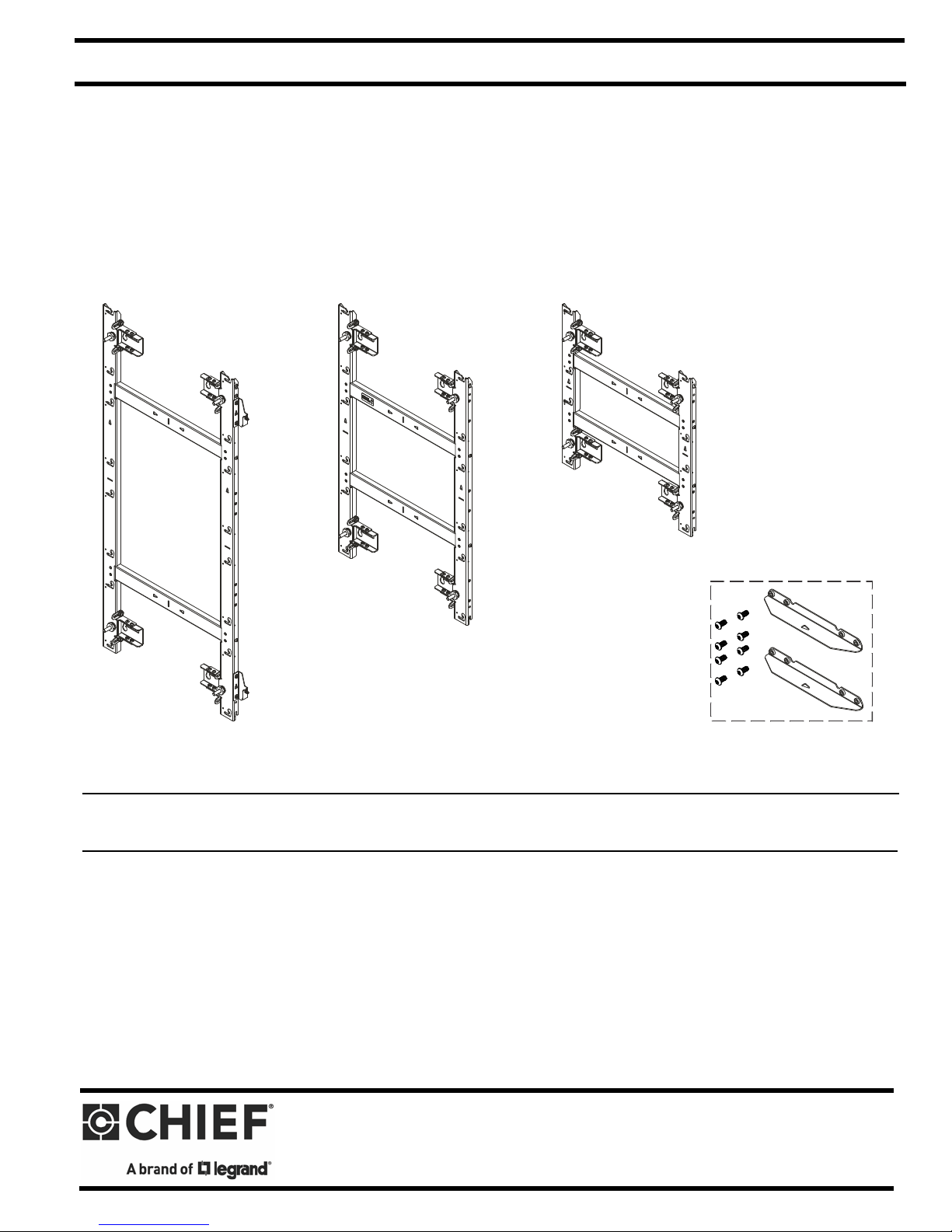
TIL1X2AA
TIL1X3AA
TIL1X4AA
TILVABAA
Accessory
AA Series LED Wall Mounts / Accessory
Spanish Product Description
German Product Description
Portuguese Product Description
Italian Product Description
Dutch Product Description
French Product Description
TILVABAA
Page 2
TIL1X2AA / TIL1X3AA / TIL1X4AA / TILVABAA Installation Instructions
DISCLAIMER
Legrand | AV and its affiliated corporations and subsidiaries
(collectively “Legrand | AV”), intend to make this manual
accurate and complete. However, Legrand | AV makes no claim
that the information contained herein covers all details,
conditions or variations, nor does it provide for every possible
contingency in connection with the installation or use of this
product. The information contained in this document is subject
to change without notice or obligation of any kind. Legrand | AV
makes no representation of warranty, expressed or implied,
regarding the information contained herein. Legrand | AV
assumes no responsibility for accuracy, completeness or
sufficiency of the information contained in this document.
DEFINITIONS
MOUNTING SYSTEM: A MOUNTING SYSTEM is the
primary Chief product to which an accessory and/or component
is attached.
ACCESSORY: AN ACCESSORY is the secondary Chief
product which is attached to a primary Chief product, and may
have a component attached or setting on it.
WARNING: The TIL1X2AA / TIL1X3AA / TIL1X4AA LED
wall mounts are designed for use with the Absen Acclaim
Series LED only. Exceeding the weight capacity (listed) can
result in serious personal injury or damage to equipment!
• TIL1X2AA: 40 lbs (18.1 kg) - 20 lbs (9.1 kg) per
module;
• TIL1X3AA: 60 lbs (27.2 kg) - 20 lbs (9.1 kg) per
module;
• TIL1X4AA: 80 lbs (36.3 kg) - 20 lbs (9.1 kg) per
module.
WARNING: Use this mounting system only for its intended
use as described in these instructions. Do not use
attachments not recommended by the manufacturer.
WARNING: Never operate this mounting system if it is
damaged. Return the mounting system to a service center for
examination and repair.
WARNING: Do not use this mounting system outdoors.
COMPONENT: A COMPONENT is an audiovisual item
designed to be attached or resting on an accessory or mounting
system such as a video camera, CPU, screen, display,
projector, etc.
WARNING: A WARNING alerts you to the possibility of
serious injury or death if you do not follow the instructions.
CAUTION: A CAUTION alerts you to the possibility of
damage or destruction of equipment if you do not follow the
corresponding instructions.
IMPORTANT SAFETY INSTRUCTIONS
WARNING: Failure to read, thoroughly understand, and
follow all instructions can result in serious personal injury,
damage to equipment, or voiding of factory warranty! It is the
installer’s responsibility to make sure all mounting systems
are properly assembled and installed using the instructions
provided.
WARNING: Failure to provide adequate structural strength
for this mounting system can result in serious personal injury
or damage to equipment! It is the installer’s responsibility to
make sure the structure to which this mounting system is
attached can support five times the combined weight of all
equipment. Reinforce the structure as required before
installing the mounting system. The wall to which the
mounting system / accessory is being attached may have a
maximum drywall thickness of 5/8” (1.6cm). Do not install
drywall anchors into the seam between drywall pieces.
IMPORTANT ! : The TIL1X2AA / TIL1X3AA /TIL1X4AA
(Absen Acclaim Series) LED wall mounts are designed to be
mounted to:
• a bare 8" concrete or 8"x8"x16" concrete block wall; or
• a 3/4" thickness plywood-backed, 2" x 4" wood studs
(16" on center minimum) wall with a maximum drywall
thickness of 5/8"; or
• a 3/4" thickness plywood-backed, steel stud wall
covered with drywall having a maximum thickness of
5/8".
--SAVE THESE INSTRUCTIONS--
2
Page 3
TIL1X2AA / TIL1X3AA / TIL1X4AA / TILVABAA Installation Instructions
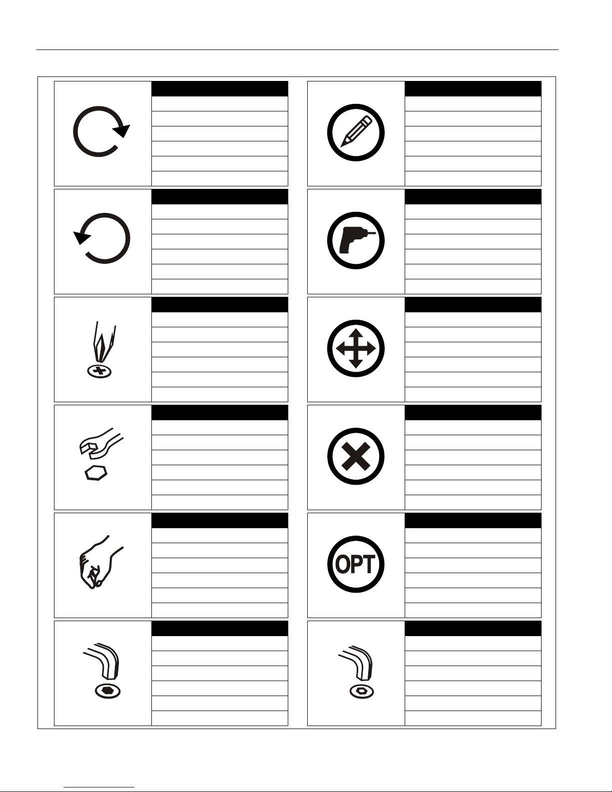
Tighten Fastener
Apretar elemento de fijación
Befestigungsteil festziehen
Apertar fixador
Serrare il fissaggio
Bevestiging vastdraaien
Serrez les fixations
Loosen Fastener
Aflojar elemento de fijación
Befestigungsteil lösen
Desapertar fixador
Allentare il fissaggio
Bevestiging losdraaien
Desserrez les fixations
Phillips Screwdriver
Destornillador Phillips
Kreuzschlitzschraubendreher
Chave de fendas Phillips
Cacciavite a stella
Kruiskopschroevendraaier
Tournevis à pointe cruciforme
Open-Ended Wrench
Llave de boca
Gabelschlüssel
Chave de bocas
Chiave a punte aperte
Steeksleutel
Clé à fourche
By Hand
A mano
Von Hand
Com a mão
A mano
Met de hand
À la main
Hex-Head Wrench
Llave de cabeza hexagonal
Sechskantschlüssel
Chave de cabeça sextavada
Chiave esagonale
Zeskantsleutel
Clé à tête hexagonale
Pencil Mark
Marcar con lápiz
Stiftmarkierung
Marcar com lápis
Segno a matita
Potloodmerkteken
Marquage au crayon
Drill Hole
Perforar
Bohrloch
Fazer furo
Praticare un foro
Gat boren
Percez un trou
Adjust
Ajustar
Einstellen
Ajustar
Regolare
Afstellen
Ajuster
Remove
Quitar
Entfernen
Remover
Rimuovere
Verwijderen
Retirez
Optional
Opcional
Optional
Opcional
Opzionale
Optie
En option
Security Wrench
Llave de seguridad
Sicherheitsschlüssel
Chave de segurança
Chiave di sicurezza
Veiligheidssleutel
Clé de sécurité
LEGEND
3
Page 4
Installation Instructions TIL1X2AA / TIL1X3AA / TIL1X4AA / TILVABAA
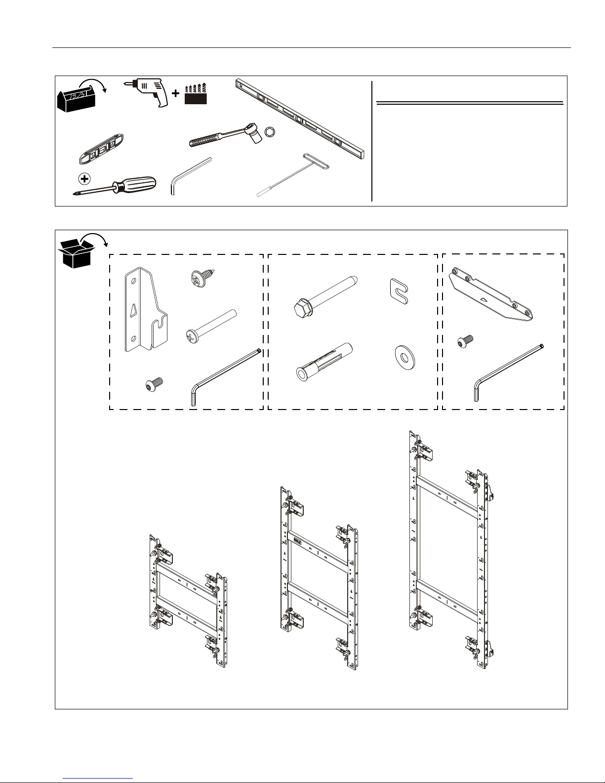
Hardware Required - not included
(for installation into steel stud walls)
1. Chief brand FCAT1 Toggler Kit; OR
2. Hardware for installation to steel stud wall:
• 1/4-20 Toggler Snaptoggle BB (Qty 4)
• 1/4-20 x 2-1/2" hex head bolt (Qty 4)
• 1/4" washer (Qty 4)
7/32"
#2
Level
[4+ ft. long]
[Small level]
3/8"
1/2"
T-Handle
drive with
1" socket
1/2"
5/32"
(included)
Horizontal Connector Kit
F (4)
5/16 x 2-1/2"
G (4)
UX10x60R
H (2)
[Installation
Connector Kit
K (2)
[Vertical connector]
L (8)
1/4-20 x 1/2"
N (1)
[TIL1X2AA]
P (1)
[TIL1X3AA]
Q (1)
[TIL1X4AA]
TILVABAA Vertical
OR
OR
Mounting Hardware Kit
washer]
J (4)
5/16"
A (2)
[Horizontal
connector]
B (8)
1/4-20 x 1/2"
C (6)
08-32 x 1/2"
D (8)
10-24 x 1-1/2"
E (1)
5/32"
M (1)
5/32"
TOOLS REQUIRED FOR INSTALLATION
PARTS
4
Page 5
Installation Instructions TIL1X2AA / TIL1X3AA / TIL1X4AA / TILVABAA
Location for top left corner of LED wall
1
2
5"
3
5”
5”
[TIL1X2AA shown as example]
3
Mounting slot
center line
2
(B) x 4
(A)
[TIL1X2AA shown as example]
INSTALLATION
Preinstallation
IMPORTANT ! : Reference the LED module installation
manual for specific instructions regarding care, handling,
cabling and installation of the LED modules.
CAUTION: Handle the LED modules with care, being
careful to not impact or drop the LED module.
CAUTION: There is a magnetic surface on the front of the
LED module. To prevent damage ensure that no metallic
object is pulled onto the LED module.
NOTE: When planning the installation, remember the
requirement to run power and signal to the video wall.
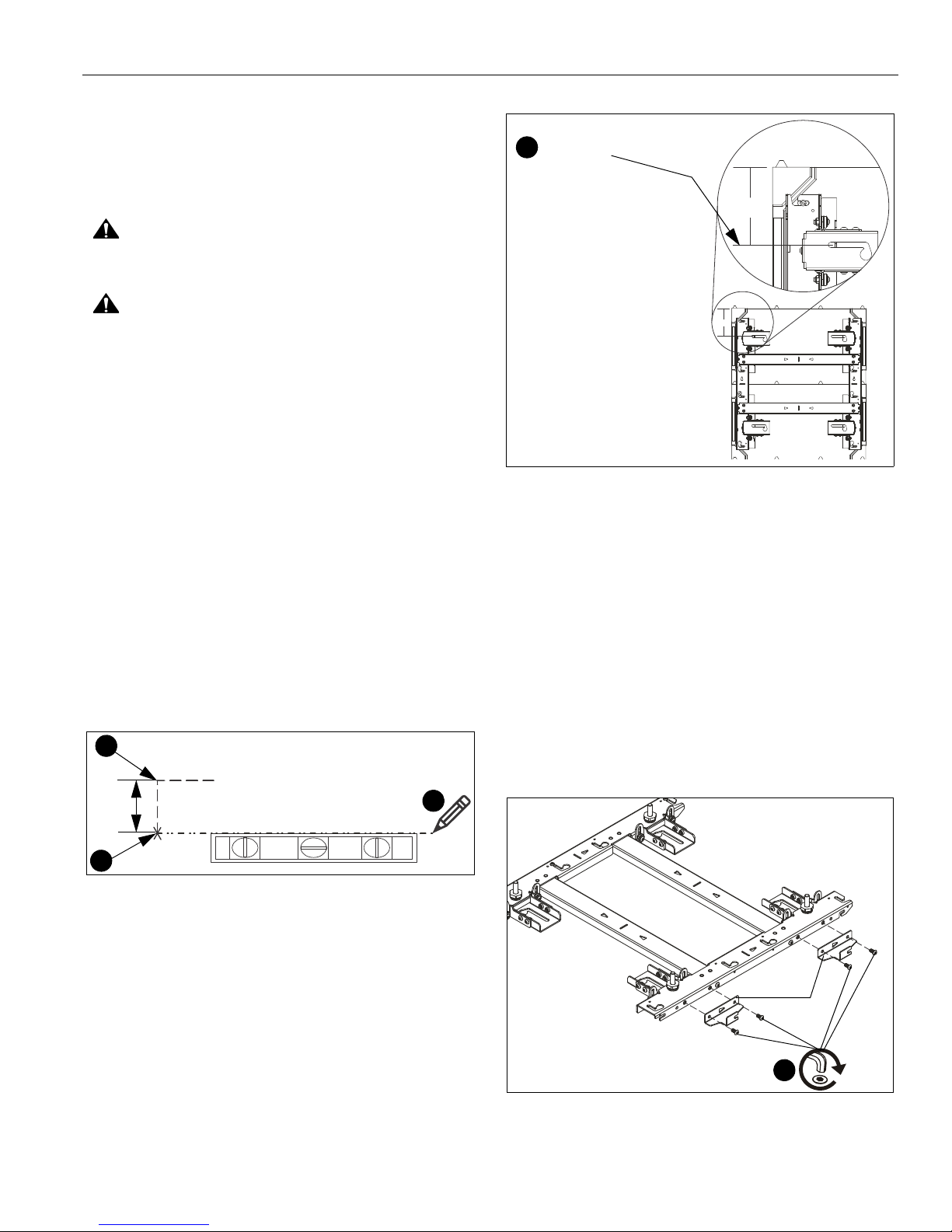
Determining Installation Site
IMPORTANT ! :
the center line of the mounting slots. (See Figure 1)
1. Determine location for the top left corner of the LED wall.
(See Figure 1)
2. Make a mark 5" below the planned top left corner of the LED
wall. (See Figure 1)
3. Using a level, mark a horizontal line across width of LED
wall from the mark made in Step 2.
NOTE:
This line will indicate the center line of the mounting slots
for the top mount(s) in the LED wall. (See Figure 1) and
(See Figure 2)
The top of the LED housing is 5" above
Figure 1
Figure 2
(OPTIONAL) Attaching Horizontal Connectors
NOTE: The horizontal connectors (A) must be attached if the
LED wall will be wider than one mount.
NOTE: It will be easier to attach the connectors before
installing the mount to the wall. However, the
connectors may still be attached after the wall mount is
already on the wall.
1. Lay mount on floor and place horizontal connectors (A)
against right edge of wall mount. (See Figure 3)
2. Attach two connectors to each wall mount using two 1/4-20
x 1/2" button head cap screws (B) per horizontal connector.
(See Figure 3)
Figure 3
5
Page 6
TIL1X2AA / TIL1X3AA / TIL1X4AA / TILVABAA Installation Instructions
2
14.25 inches
3
Line showing
slots for top
mounts in LED wall
center of mounting
[TIL1X2AA shown as example]
4
5
x 2
[TIL1X2AA shown as example]
Indicates
center line
of the mount
horizontal
Indicates approximate
center line between
two LED modules
Installing First Mount
The TIL1X2AA / TIL1X3AA /TIL1X4AA (Absen Acclaim Series)
LED wall mounts are designed to be mounted to:
• a bare 8" concrete or 8"x8"x16" concrete block wall; or
• a 3/4" thickness plywood-backed, 2" x 4" wood studs
(16" on center minimum) wall with a maximum drywall
thickness of 5/8"; or
•
a 3/4" thickness plywood-backed, steel stud wall
covered with drywall having a maximum thickness of
5/8".
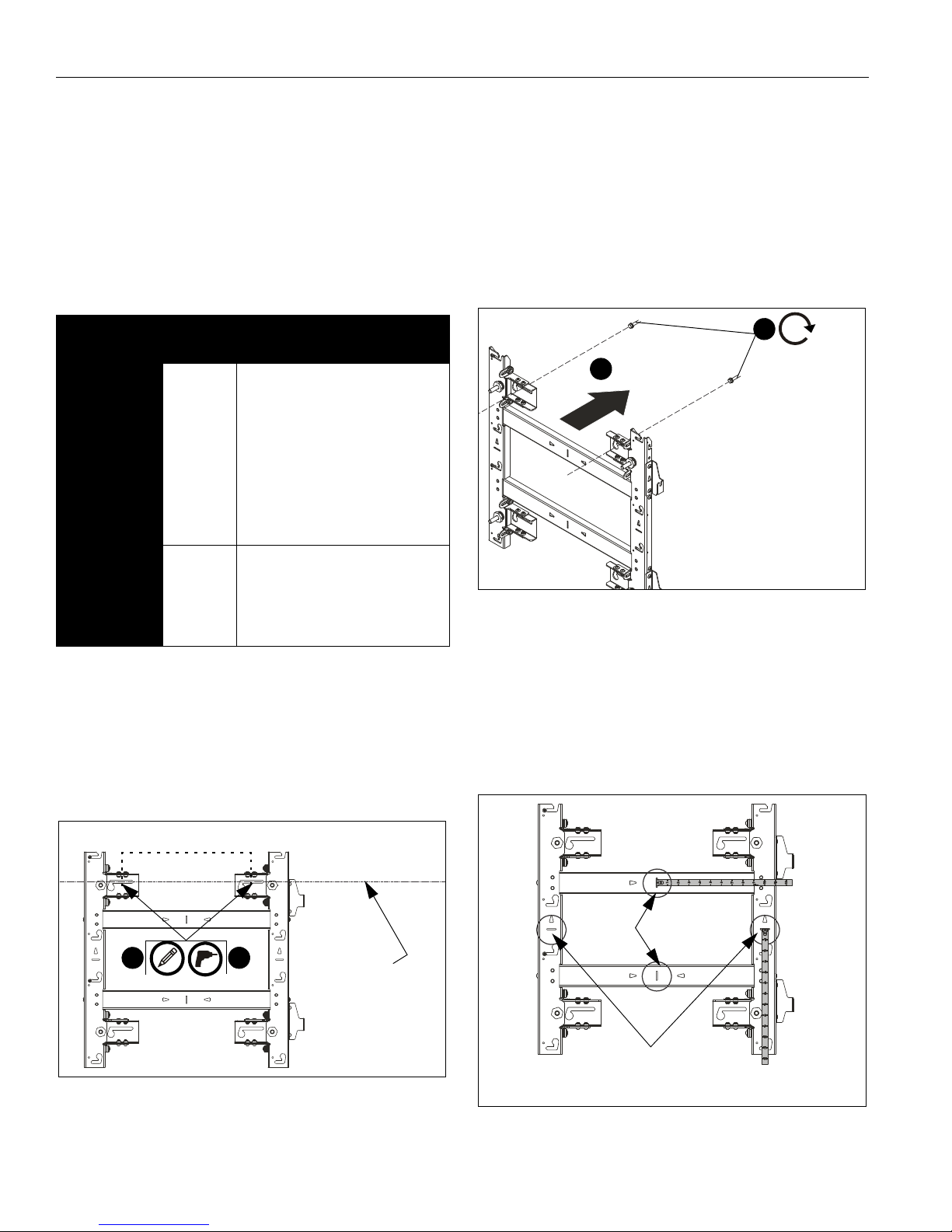
Table 1: Fastener Information
WALL
TYPE
Drywall
attached to
plywoodbacked walls
/Steel studs
Drywall
attached to
plywoodbacked walls
/Wood studs
PILOT
HOLE
1/2"
7/32" x 3"
FASTENERS (see PARTS
drawing)
- 1/4-20 x 2-1/2" hex head lag (not
included)
- 1/4" washer (not included)
- 1/4-20 Toggler Snaptoggle BB
(not included)
- 5/16 x 2-1/2" flanged hex head
lag (F)
- 5/16" washer (J)
- Installation washer (H)
IMPORTANT ! : Refer to Fastener Installation Methods
(located in Appendix at end of Installation Instructions)
for details on installing product into various wall types.
4. Partially install two fasteners into wall, but do NOT
completely tighten to wall. (See Figure 5)
NOTE: Utilizing the two U-shaped installation washers (H)
allows the installer to pre-install the top mounting
fasteners and hang the mount from them utilizing the
mount’s teardrop slots. This allows the weight of the
mount to be held by the mounting bolts and not the
installer during installation.
3/8" x 3" - 5/16 x 2-1/2" flanged hex head
Concrete or
concrete
block
1. Hold furthest left, top wall mount against wall ensuring that
mounting slot is lined up with center line marked on the wall
in Determining Installation Site section. Double-check
with a level. (See Figure 4)
2. Mark mounting holes in two top mounting slots along the
horizontal line marked in Step 3. (See Figure 4)
lag (F)
- 5/16" washer (J)
- Installation washer (H)
- Fischer Anchor UX10x60R (G)
NOTE: The center of the mounting holes are 14.25" apart on-
center. (See Figure 4)
Figure 4
3. Drill two pilot holes (see Table 1 for size) at each location
marked in Step 2 (See Figure 4) and follow fastener
information (appropriate for wall type) located in Table 1.
6
Figure 5
5. Hang wall mount, aligning upper teardrop slots over
fasteners, and adjust side-to-side for proper location. (See
Figure 5)
NOTE: The horizontal slots located along the vertical mount
pieces indicate the approximate center line of the two
LED modules. The vertical slots located along the
horizontal mount pieces indicate the horizontal center
line of the mount. The slots can be used to hold a tape
measure tab while measuring. (See Figure 6)
Figure 6
Page 7

Installation Instructions TIL1X2AA / TIL1X3AA / TIL1X4AA / TILVABAA
Level placed
across flat of
mounting holes
Level along
side of
mount
6
6
7
(H) x 2
6
Level placed along
center-of-LED
modules indicator
9
x 2
8
x 2
10
(L) x 4
(K)
(L) x 2
(K)
Top
mount
Lower
mount
Hang open slot onto
partially installed button
head screw (L) and tighten
both screws (L).
6. Lay levels across flat of the mounting holes and center line
indicators, and vertically along side of mount to ensure wall
mount is square and level. (See Figure 7)
7. Slide installation washers (H) behind head of fasteners and
tighten mount in place. (See Figure 7)
• Add the vertical connector (K) to the top or bottom of
the mount, and fasten with two 1/4-20 x 1/2" button
head cap screws (L) per vertical connector. (See
Figure 9)
• Connect another wall mount to the other end of the
vertical connector to lengthen the LED wall.
Figure 7
8. Drill lower pilot holes (see Table 1 for size) at attachment
locations and follow fastener information (appropriate for
wall type) located in Table 1. (See Figure 8)
9. Install two fasteners through lower part of mount and
tighten. (See Figure 8)
NOTE:
Figure 9
When connecting a mount to the bottom of an installed
mount, the lower mount may be hung by its open slot
on the partially installed button head screw (L) before
tightening the connection. (See Figure 10)
10. (OPTIONAL) If more LED housings need to be added to the
top or bottom of the screen configuration, add TILVABAA
vertical connector kit (not included) to top or bottom of wall
mount. If you are NOT adding the TILVABAA connector kit,
proceed to Step 11.
Figure 8
Figure 10
7
Page 8

TIL1X2AA / TIL1X3AA / TIL1X4AA / TILVABAA Installation Instructions
Leveling feet
locations
11
Model Fastener
Qty
TIL1X4AA 4
TIL1X3AA 3
TIL1X2AA 2
[TIL1X2AA shown as example]
12
(C)
11. Using a level on the front of the mount in various places, use
a 1" socket and T-handle driver to adjust the leveling feet on
the mount until the mount is plumb. (See Figure 11)
CAUTION: Over-torquing may cause damage. Do NOT
use a drill to make the depth adjustment.
12. Install one 8-32 x 1/2" Phillips tapping screw (C) into left
Figure 11
upper LED mounting button hole for each LED screen
space. (See Figure 12)
Figure 12
IMPORTANT ! : The tapping screws keep the LED
modules centered on the mount, and are ONLY
on the furthest left column of mounts.
installed
NOTE: Using a drill driver makes installation of the tapping
screws (C) easier.
8
Page 9

Installation Instructions TIL1X2AA / TIL1X3AA / TIL1X4AA / TILVABAA
(B) x 2
1
2
(B) x 2
[TIL1X2AA shown as example]
Second
mount
2
4
String to assist
with alignment
9
[Multiple TIL1X2AA shown as example
for using string to assist with alignment.]
(C)
8
Screw holes for
attaching string are
located at each
mounting button slot
Self-tapping screws
Adding Additional Mounts
1. Partially install two 1/4-20 x 1/2" button head screws (B) into
the left side of the next mount. (See Figure 13)
2. Connect second mount to the right side of the already
installed mount hanging it by the 1/4-20 x 1/2" button head
screws (B) onto each horizontal connector on the mounts
right side. (See Figure 14)
NOTE: For larger LED walls it is helpful to check placement
and alignment by putting a few housings in place during
the installation, checking alignment before removing
the housings, and then continuing the installation.
3. Use a level to align the second mount with the first mount.
4. Tighten both fasteners (where the second mount is hung on
the first mount) to fasten two mounts together. (See
Figure 14)
5. Drill pilot holes in the mounting slots and fasten the second
wall mount to the wall following the same steps as used for
the first wall mount.
6. Recheck the alignment and overall flatness of the wall
mounts during the installation process.
7. Continue the installation process until all wall mounts are
attached.
8. Install the 8-32 x 1/2" self-tapping screws (C) on the mount
to attach string for alignment. (See Figure 15)
Figure 13
Figure 14
Figure 15
9. Run a string between the self-tapping screws installed in
Step 8 to assist with alignment across long sections of
mounts. (See Figure 15)
9
Page 10

TIL1X2AA / TIL1X3AA / TIL1X4AA / TILVABAA Installation Instructions
2
LED Housing
[TIL1X2AA shown as example]
Front view
Back
view
8
(D) x 2
[per module]
Installing Housings and LED Screens
IMPORTANT ! : Reference the LEDs installation manual
for specific instructions regarding care, handling, cabling
and installation of the LED housings and modules.
NOTE:
NOTE: One complete column of housings should be installed
1. Install the first LED housing in the lowest left-hand corner of
2. Move LED housing forward until all four mounting buttons
3. Lower housing until contacting the bottom of mounting
Begin the installation of the housings in the lower left
corner of the video wall.
before proceeding to the next column.
the video wall by aligning mounting buttons on the housing
with the mounting holes on the wall mount.
are through mounting holes in wall mount.
holes. (See Figure 16)
4. Continue with the next housing (directly above installed
housing).
NOTE: Be sure to check the level and plumb of the housings
5. AFTER the entire
6. After the second column is installed, push to the left until the
7. Repeat until all housings are installed.
8. Install two 10-24 x 1-1/2" Phillips head cap screws (D) per
NOTE: The screws (D) are installed from the right side of the
occasionally during the housing installation.
slide the column to the left side so that the mounting buttons
are against the tapping screws, and to allow clearance for
installation of the second column.
first and second columns of housings are touching.
housing on far right column of mounts. (See Figure 17)
furthest right wall mount and can be used to push the
housings to the left and to prevent removal of the LED
modules. The screws can also be used to slightly level
or align the housings by adjusting the amount of push
at the bottom or top of the housing.
Figure 16
first column of housings are installed,
Figure 17
9. Using levels, check the level and plumb of the housings
installed on the mounts and adjust as necessary following
information in the Adjustments section.
10. Only AFTER
necessary and are in the final, required position cam
housings together following instructions included with
LEDs.
11. Install LED modules following instructions included with
LEDs.
the housings have been adjusted as
10
Page 11

Installation Instructions TIL1X2AA / TIL1X3AA / TIL1X4AA / TILVABAA
Leveling feet
locations
1
[LED housings not shown]
1
2
(F)
(J)
1
2
(F)
(G)
(J)
Adjustments
Depth Adjust
The depth of each wall mount section is controlled by the
leveling feet.
1. Using a level on the front of the housings in various places,
loosen or tighten the leveling feet adjust bolt (using a 1"
socket and T-handle driver) to assist in leveling the LED
housings across the various wall mounts until plumb. (See
Figure 18)
CAUTION: Over-torquing may cause damage. Do NOT
use a drill to make the depth adjustment.
Figure 19
Concrete or Concrete Block
1. Install one UX10X60R anchor (G) into each pilot hole using
a hammer, making sure that the anchor is flush with the wall.
(See Figure 20)
2. Use one 5/16" x 2-1/2" hex flange head lag bolt (F) and one
5/16" washer (J) through product into each anchor in wall.
(See Figure 20)
3. Repeat for remaining pilot holes.
Figure 18
Fastener Installation Methods
IMPORTANT ! : See Table 1 for appropriate hardware
and pilot hole sizes for various wall types.
IMPORTANT ! : The expanse of the LED wall will most
likely mean that attachment of the wall mounts will not all
be in studs. The attachment method will most likely vary
throughout the installation, and more than one of the
various methods outlined here will most likely be used.
Wood Stud
1. Use one 5/16" x 2-1/2" hex flange head lag bolt (F) and one
5/16" washer (J) through product and into pilot hole. (See
Figure 19)
2. Repeat for remaining pilot holes.
Figure 20
11
Page 12

TIL1X2AA / TIL1X3AA / TIL1X4AA / TILVABAA Installation Instructions
Drywall
Plastic straps
1
Plastic cap
Drywall
Anchor metal channel
3
Steel stud
(side view)
2
(if present)
Plastic straps
Drywall
Anchor metal channel
Plastic cap
4
Steel stud
(side view)
(if present)
Drywall
Anchor metal channel
Phillips
6
Steel stud
Washer
(side view)
Wall bracket
(if present)
screw
Steel Stud
IMPORTANT ! : See Site Requirements for Steel Stud
Installation section before proceeding with Steel Studs
installation to ensure installation site meets requirements!
The drywall must have a minimum thickness of 1/2"!
1. Hold metal channel on anchor flat alongside plastic straps
and slide channel through hole. (See Figure 21)
Figure 21
2. Holding plastic straps on anchor, pull anchor away from wall
until channel rests flush behind wall making sure anchor
channel is positioned vertically on drywall, or steel stud (if
present). (See Figure 22)
3. Slide plastic cap on anchor towards wall until flange of cap
is flush with wall. (See Figure 22)
5. Line up anchor with attachment point.
6. Insert 1/4-20 x 1-3/4" Phillips pan head screw through 1/4"
washer, corresponding mounting hole in wall bracket and
into anchor, and tighten until flush against wall bracket. DO
NOT over tighten! (See Figure 24)
Figure 24
Figure 22
4. Snap off plastic straps on anchor at wall by pushing side to
side, snapping off straps level with flange of plastic cap.
(See Figure 23)
Figure 23
12
Page 13

Installation Instructions TIL1X2AA / TIL1X3AA / TIL1X4AA / TILVABAA
FRONT
There must be a minimum of
1-7/8" (48mm) clearance
inside wall
16" or 24" (on center) Studs
If back side of wall is unfinished,
to a minimum of one stud left
drywall must be installed
and right of the stud(s) being used
to install the mount. Drywall must be
secured to studs with screws a
maximum of 12" (305mm) apart
down center of stud.
Steel Stud (2 x 4 / 25ga minimum)
Stud type and structural strength must conform to the North American
Specification for the Design of Cold-Formed Steel Structural Members.
(Both Sides of Stud)
[362 S 125 18, C-Shaped, S-Stud Section]
Plywood
3/4" minimum thickness
plywood covered
with drywall having
maximum thickness of 5/8"
5/8" maximum
drywall thickness
Stud
Site Requirements for Wood or Steel Stud Installation
Figure 25
13
Page 14
Installation Instructions TIL1X2AA / TIL1X3AA / TIL1X4AA / TILVABAA
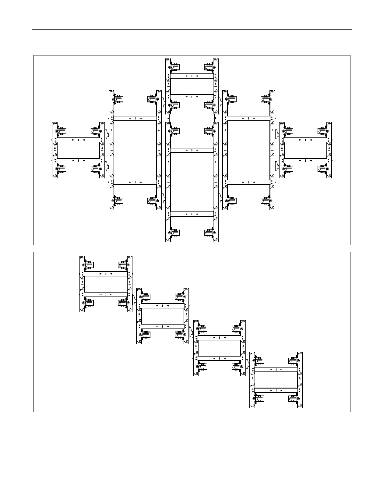
Configuration Examples
The following are just two examples of the many configurations which are possible with the AA Series wall mounts.
14
Page 15

TIL1X2AA / TIL1X3AA / TIL1X4AA / TILVABAA Installation Instructions
TIL1X2AA
DIMENSIONS: INCHES
[MILLIMETERS]
DIMENSIONS
15
Page 16

Installation Instructions TIL1X2AA / TIL1X3AA / TIL1X4AA / TILVABAA
TIL1X3AA
DIMENSIONS: INCHES
[MILLIMETERS]
DIMENSIONS...cont’d
16
Page 17

TIL1X2AA / TIL1X3AA / TIL1X4AA / TILVABAA Installation Instructions
DIMENSIONS: INCHES
[MILLIMETERS]
TIL1X4AA
DIMENSIONS...cont’d
17
Page 18

Installation Instructions TIL1X2AA / TIL1X3AA / TIL1X4AA / TILVABAA
TILVABAA
DIMENSIONS: INCHES
[MILLIMETERS]
11.0
279.0
DIMENSIONS...cont’d
18
Page 19

TIL1X2AA / TIL1X3AA / TIL1X4AA / TILVABAA Installation Instructions
19
Page 20

TIL1X2AA / TIL1X3AA / TIL1X4AA / TILVABAA Installation Instructions
8800-003104 Rev00
2018 Legrand | AV
www.legrandav.com
12/18
USA/International A 6436 City West Parkway, Eden Prairie, MN 55344
P 800.582.6480 / 952.225.6000
F 877.894.6918 / 952.894.6918
Europe A Franklinstraat 14, 6003 DK Weert, Netherlands
P +31 (0) 495 580 852
F +31 (0) 495 580 845
Asia Pacific A Office No. 918 on 9/F, Shatin Galleria
18-24 Shan Mei Street
Fotan, Shatin, Hong Kong
P 852 2145 4099
F 852 2145 4477
 Loading...