

Page 1
INSTALLATION INSTRUCTIONS
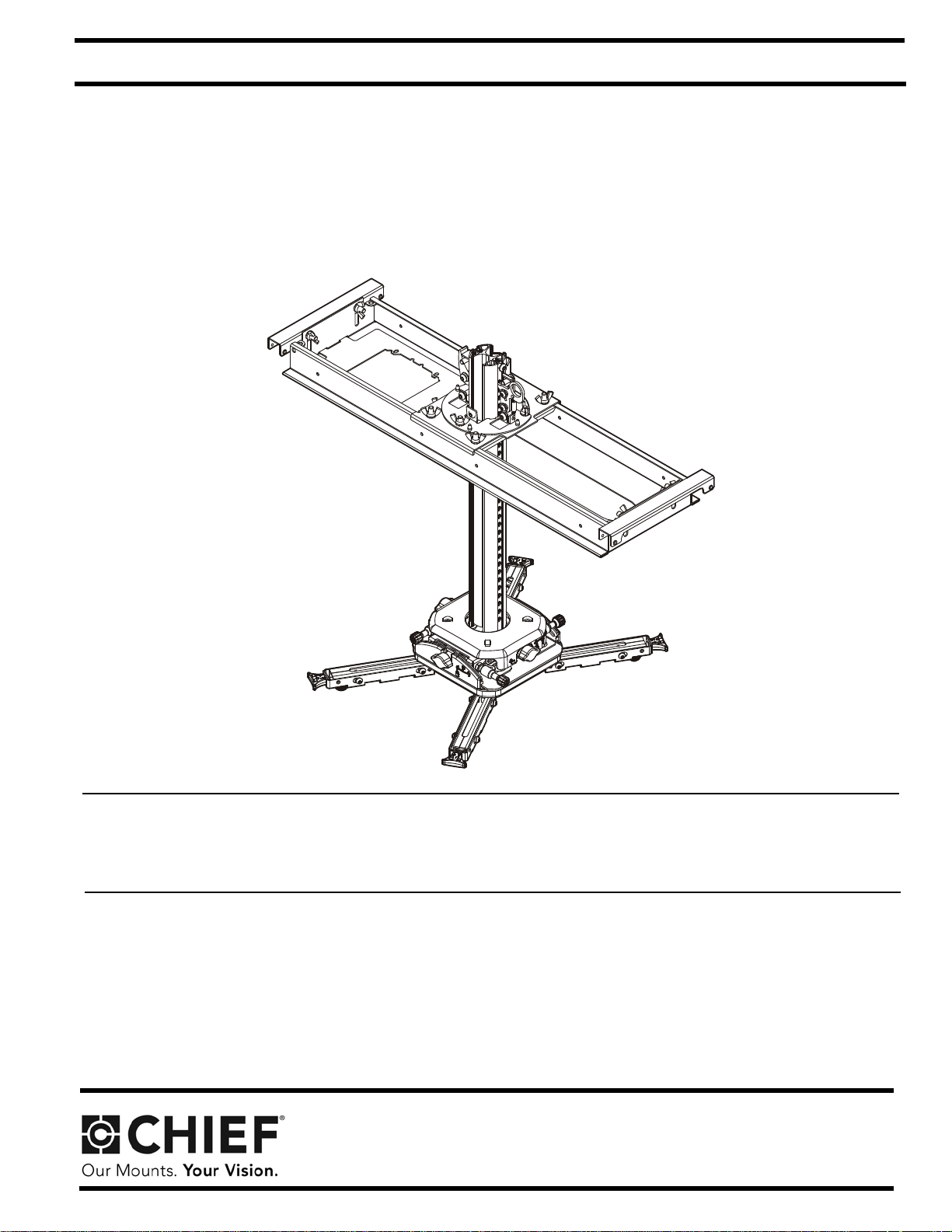
Universal Interface Suspended Ceiling
Projector System
SYSAU
Page 2
SYSAU Installation Instructions
DISCLAIMER
Milestone AV Technologies and its affiliated corporations and
subsidiaries (collectively “Milestone”), intend to make this
manual accurate and complete. However, Milestone makes no
claim that the information contained herein covers all details,
conditions or variations, nor does it provide for every possible
contingency in connection with the installation or use of this
product. The information contained in this document is subject
to change without notice or obligation of any kind. Milestone
makes no representation of warranty, expressed or implied,
regarding the information contained herein. Milestone assumes
no responsibility for accuracy, completeness or sufficiency of
the information contained in this document.
Chief® is a registered trademark of Milestone AV Technologies.
All rights reserved.
WARNING:
serious personal injury or damage to equipment! It is the
installer’s responsibility to make sure the combined weight of
all components attached to the SYSAU does not exceed 35 lbs
(15.9 kg).
WARNING: Use this mounting system only for its intended
use as described in these instructions. Do not use
attachments not recommended by the manufacturer.
WARNING: Never operate this mounting system if it is
damaged. Return the mounting system to a service center for
examination and repair.
Exceeding the weight capacity can result in
DEFINITIONS
MOUNTING SYSTEM: A MOUNTING SYSTEM is the
primary Chief product to which an accessory and/or component
is attached.
ACCESSORY: AN ACCESSORY is the secondary Chief
product which is attached to a primary Chief product, and may
have a component attached or setting on it.
COMPONENT: A COMPONENT is an audiovisual item
designed to be attached or resting on an accessory or mounting
system such as a video camera, CPU, screen, display,
projector, etc.
WARNING: A WARNING alerts you to the possibili ty of
serious injury or death if you do not follow the instructions.
CAUTION: A CAUTION alerts you to the possibility of
damage or destruction of equipment if you do not follow the
corresponding instructions.
WARNING: Do not use this product outdoors.
IMPORTANT ! : The SYSAU has been designed to be
mounted above or flush with a suspended ceiling secured by a
WireVice system.
IMPORT ANT ! : The SYSAU has been designed to support a
single electrical receptacle, a double electrical receptacle or
both.
NOTE: It is the installer’s responsibility to ensure that the
enclosure is bonded to the ground in the switch box, in
accordance with the National Electric Code, ANSI/
NFPA 70 or Canadian Electrical Code, CSA C22.1.
--SAVE THESE INSTRUCTIONS--
IMPORTANT SAFETY INSTRUCTIONS
WARNING: Failure to read, thoroughly understand, and
follow all instructions can result in serious personal injury,
damage to equipment, or voiding of factory warranty! It is the
installer’s responsibility to make sure the mounting system is
properly assembled and installed using the instructions
provided.
WARNING: Failure to provide adequate structural strength
for this mounting system can result in serious personal injury
or damage to equipment! It is the installer’s responsibility to
make sure the structure to which this mounting system is
attached can support five times the combined weight of all
equipment. Reinforce the structure as required before
installing the mounting system.
2
Page 3
Installation Instructions SYSAU
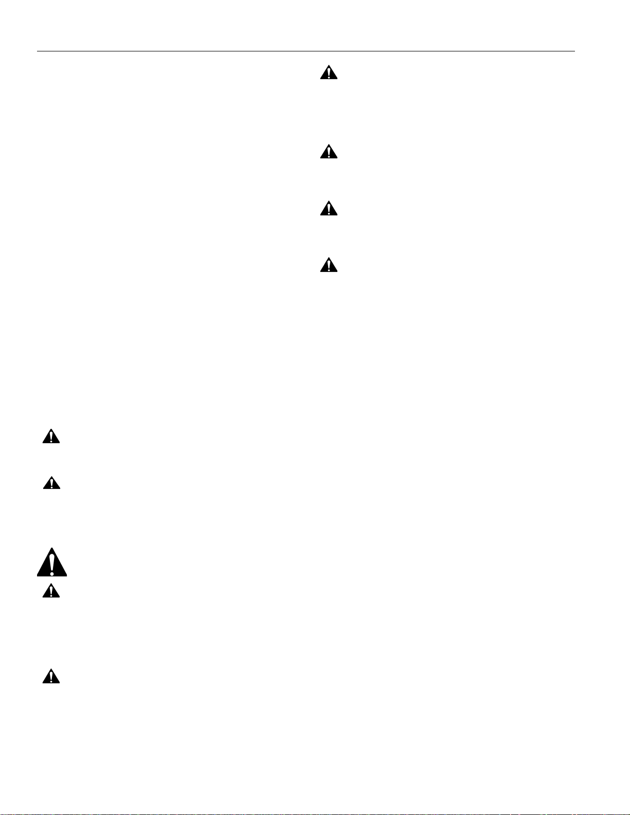
360 DEGREES OF COLUMN
ROTATION
REMOVABLE ELECTRICAL
INSTALL PLATE
SET SCREW LOCATIONS PROVIDED
TO SECURE PLATE TO CEILING GRID
234.2
9.22
COLUMN TRAVEL
300.8
11.84
155.4
6.12
184.2
7.25
116.8
4.60
66.5
2.62
50.3
1.98
POSITION FOR COLUMN
SECURITY BOLT
MOVEABLE/REMOVABLE
HOOKS
COLUMN LATCH
COLUMN CLAMP LEVER
589
23.19
592
23.31
633.6
24.94
47.7
1.88
21.5
.85
1.03 ADJUSTMENT RANGE
DIMENSIONS: [MILLIMETERS]
INCHES
14.74
374.3
5.08
129.1
294.7
11.60
12.7
.50
COLUMN ADJUSTMENT
INCREMENT
8.6
.34
88.3
3.48
415.2
16.35
79.7
3.14
503.5
19.82
MOUNT AND
COLUMN ASSEMBLED
NOTE:
THIS IS A 4 SHEET DRAWING
1.
SHEET 2 - CEILING PLATE2.
SHEET 3 - PROJECTOR MOUNT AND COLUMN3.
SHEET 4 - UNIVERSAL INTERFACE4.
DIMENSIONS: [MILLIMETERS]
INCHES
DIMENSIONS
3
Page 4
SYSAU Installation Instructions
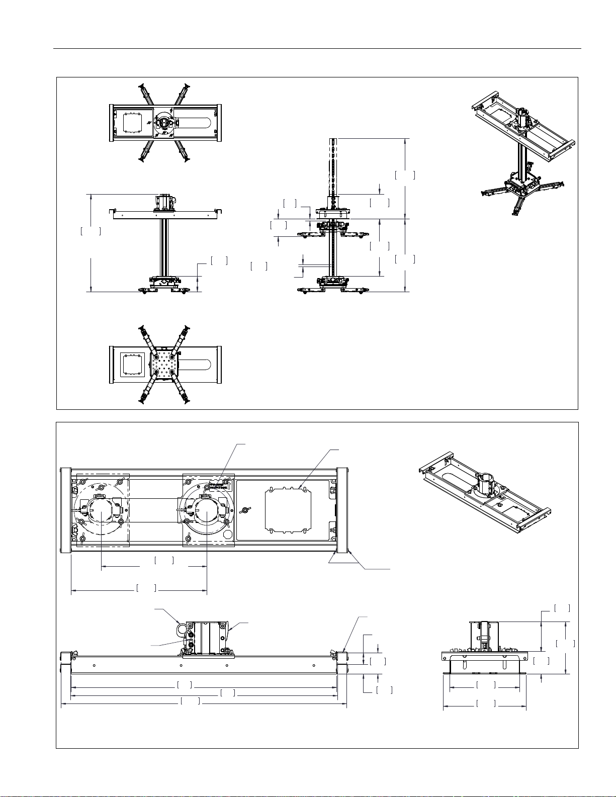
10° YAW ADJUSTMENT
PITCH MICRO
ADJUST KNOB
PITCH
MICRO/MACRO
ADJUST KNOB
176.6
6.95
10° PITCH ADJUSTMENT
ROLL
MICRO/MACRO
ADJUST KNOB
ROLL MICRO
ADJUST KNOB
3° ROLL ADJUSTMENT
YAW
MICRO/MACRO
ADJUST KNOB
YAW MICRO
ADJUST KNOB
45.1
1.78
177.8
7.00
CABLE ROUT ING TIE-OFF (4)
DIMENSIONAL VIEWS OF MOUNT SHOWN WITHOUT CO LUMN
TO INCREASE CLARITY
DIMENSIONS: [MILLIMETERS]
INCHES
353.3
13.91
348.9
13.73
115.7
R4.55
100.2
3.94
115.2
4.53
143.3
5.64
34.5
1.36
153
6.02
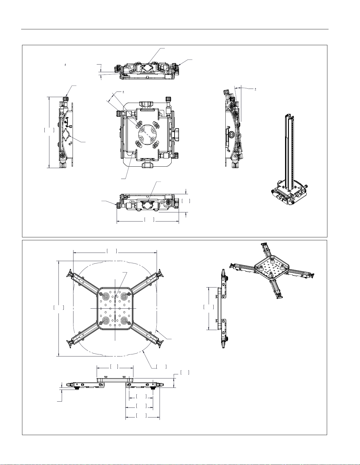
ADJUSTABLE
FEET
157.8
6.21
MOUNTING PATTERN LIMITS
PROJECTOR LENS DIRECTION
ALIGNMENT MARK
NOTE:
INTERFACE SHOWN ASSEMBLED, SHIPPED AS LOO SE PIECES1.
FOUR LEGS SHOWN, A MINIMUM OF THREE LEGS MUST BE USED
2.
TO PROPERLY MOUNT THE PROJECTOR
DIMENSIONS: [MILLIMETERS]
INCHES
DIMENSIONS - continued
4
Page 5
Installation Instructions SYSAU
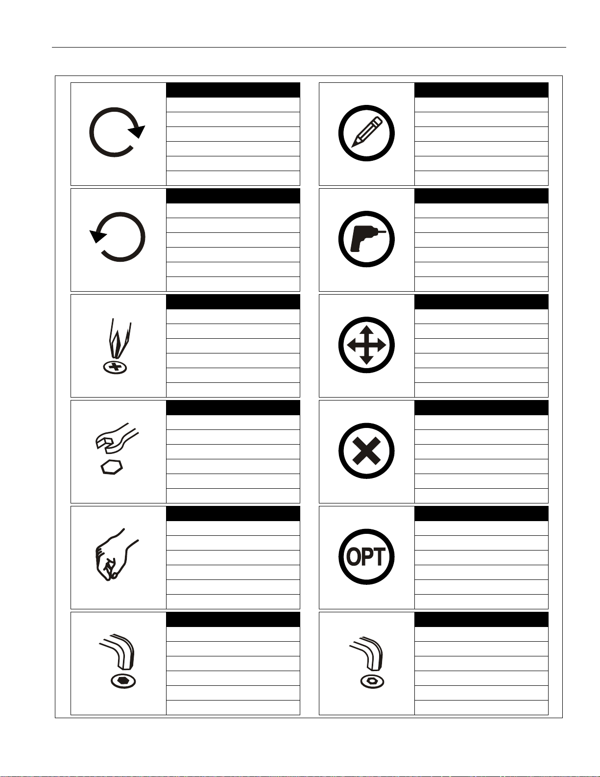
Tighten Fastener
Apretar elemento de fijación
Befestigungsteil festziehen
Apertar fixador
Serrare il fissaggio
Bevestiging vastdraaien
Serrez les fixations
Loosen Fastener
Aflojar elemento de fijación
Befestigungsteil lösen
Desapertar fixador
Allentare il fissaggio
Bevestiging losdraaien
Desserrez les fixations
Phillips Screwdriver
Destornillador Phillips
Kreuzschlitzschraubendreher
Chave de fendas Phillips
Cacciavite a stella
Kruiskopschroevendraaier
Tournevis à pointe cruciforme
Open-Ended Wrench
Llave de boca
Gabelschlüssel
Chave de bocas
Chiave a punte aperte
Steeksleutel
Clé à fourche
By Hand
A mano
Von Hand
Com a mão
A mano
Met de hand
À la main
Hex-Head Wrench
Llave de cabeza hexagonal
Sechskantschlüssel
Chave de cabeça sextavada
Chiave esagonale
Zeskantsleutel
Clé à tête hexagonale
Pencil Mark
Marcar con lápiz
Stiftmarkierung
Marcar com lápis
Segno a matita
Potloodmerkteken
Marquage au crayon
Drill Hole
Perforar
Bohrloch
Fazer furo
Praticare un foro
Gat boren
Percez un trou
Adjust
Ajustar
Einstellen
Ajustar
Regolare
Afstellen
Ajuster
Remove
Quitar
Entfernen
Remover
Rimuovere
Verwijderen
Retirez
Optional
Opcional
Optional
Opcional
Opzionale
Optie
En option
Security Wrench
Llave de seguridad
Sicherheitsschlüssel
Chave de segurança
Chiave di sicurezza
Veiligheidssleutel
Clé de sécurité
LEGEND
5
Page 6

SYSAU Installation Instructions
#2
5/32"
(security)
[included]
(A) Hardware Bag 9900-002214 [Hardware bag markings match second letter of hardware]
AA (4)
M2.5x10mm
AB (4)
M3x10mm
AC (4)
M4x10mm
AD (4)
M5x14mm
AE (4)
M6x14mm
AF (4)
M4x25mm
AG (4)
M6x25mm
AH (4)
M5x25mm
AI (4)
M3x25mm
AJ (4)
M4
AK (4)
.500x.256x.625"
AL1 (4)
10-24 x 3/8"
AL2 (1)
5/32" (security)
AM (4)
[Screw adapters]
AN (4)
1/4-20
(B) Hardware Bag 9900-002225 [Hardware bag markings match second letter of hardware]
BA (1)
[Column trim ring]
BB (1)
[Ceiling tile cutter]
BC (4)
.262 x 1-5/16"
BD (4)
[Cable lock]
BE (4)
1/4" x 2"
BF (1)
1/4-20 x 5/8"
BG1 (1)
10-24 x 1/4"
(security)
BG2 (1)
5/32"
(security)
BH (8)
10-24 x 5/8"
BI (4)
1/16" x 25’
[Cable]
[Screw eye]
[Wire anchor]
[Projector
mount and
column]
[Suspended ceiling plate assembly]
[Universal interface plate]
[Universal interface leg]
P (1)
R (1)
Q (4)
S (1)
(security)
TOOLS REQUIRED FOR INSTALLATION
PARTS
6
Page 7

Installation Instructions SYSAU
(AA through AI) x 3 or 4
(AJ)
(with AA or AB only)
2
(AM)
Fully
3
Height-adjustable
nut
lowered
LOCKED
UNLOCKED
(Q)
5
ASSEMBLY AND INSTALLATION
Attach Universal Interface to Projector
WARNING:
serious personal injury or damage to equipment! It is the
installer’s responsibility to make sure the combined weight of
all components attached to the SYSAU do es not exceed 35 lbs
(15.9 kg).
CAUTION: USING SCREWS OF IMPROPER SIZE MAY
DAMAGE PROJECTOR. Properly sized screws will easily
and completely thread into projector threaded inserts.
1. Determine proper size screw to fit the threaded inserts in
projector. Test Phillips screws (AA-AE) provided until one
fits the projector holes.
2. Insert screws through M4 flat washers (AJ), if required,
screw adapters (AM) with height-adjustable nuts and into
projector threaded inserts. (See Figure 1)
IMPORTANT ! : At least three or, if possible, four
interface legs MUST be used to attach projector to
universal interface plate.
NOTE:
Exceeding the weight capacity can result in
Only use washers (AJ) if using AA or AB screws to
attach screw adapters (AM) to projector.
IMPORTANT ! : The longer screws (AF through AI) and
spacers (AK) may be used if there is interference
between interface legs and any part of the projector, and
if more height is required to clear elevated surfaces of the
projector.
Figure 2
NOTE:
3. Adjust height-adjustable nuts (on screw adapters [AM]) to
desired level. (See Figure 2)
Figure 1
Make sure interface legs (Q) are in the UNLOCKED
position. (See Figure 3)
NOTE: Height-adjustable nuts should be adjusted as low as
possible while still allowing interface legs (Q) to clear
elevated surfaces on the projector. (See Figure 2)
Adjust height-adjustable nuts to the same level on all
adapter screws to ensure a level mount.
Figure 3
7
Page 8

SYSAU Installation Instructions
(Q) x 3 or 4
4
(AM) x 3 or 4
Example: 3 leg attachment
security
holes (4 per leg)
Example: 3 leg attachment
(AN) x 3
8
Sliding mounting
screws
(P)
4. Place interface legs (Q) over screw adapters (AM). (See
Figure 4)
Figure 4
5. Ensure that interface leg is firmly seated over screw
adapter, and pull out end of interface leg to lock in place
over screw adapter. (See Figure 3)
6. Repeat Step 5 for remaining legs.
7. If projector security is required, fasten one 10-24 x 3/8"
security button head screw (AL1) through one of the four
security holes in EACH leg using the 5/32" security hex key
(AL2). (See Figure 4)
WARNING: BE SURE THAT UNIVERSAL INTERFACE
LEGS ARE LOCKED OVER SCREW ADAPTERS. Projector
may fall from the mount causing serious injury or death if legs
are not securely locked over screw adapters!
8. Maneuver interface legs (Q) and slide mounting screws in
top of interface legs so that mounting screws are properly
located to mount universal interface plate (P) over
projector’s center of gravity via attachment to interface legs.
(See Figure 5)
9. Secure interface plate to interface legs by installing 1/4-20"
wing nuts (AN) to screws on interface legs. (See Figure 5)
NOTE: The following example is one possible scenario based
on one example projector hole pattern. Specific
connection points vary dependent on projector hole
pattern. Multiple scenarios may be used for each
specific hole pattern as long as the weight of the
projector is centered and balanced after mounting.
IMPORTANT ! : At least three or, if possible, four
interface legs MUST be used to attach projector to
universal interface plate.
Figure 5
8
Page 9

Installation Instructions SYSAU
1
Electrical plate
2
6
= 1.5" (38mm)
(R)
7
8
10
9
x 4
9
9
INSTALLING THE SUSPENDED CEILING PLAT E
NOTE: The SYSAU has been designed to be mounted above
or flush with a suspended ceiling secured by a
WireVice system. The method used may be
determined by the existing ceiling system.
1. Remove outlet plate from suspended ceiling plate assembly
(R) if electrical outlet will be installed (See Figure 6), and
install UL Listed Raco 256, 232 or equivalent UL Listed
electrical box (not included) to SYSAU outlet plate following
instructions included with electrical box.
4. Installing on Top of Existing Ceiling Tile only: Press
center tip of ceiling tile cutter (BB) into finished side of
ceiling tile at marked location. Cut extension column hole
through tile using back and forth motion.
5. Installing on Top of Existing Ceiling Tile only: Reinstall
ceiling tile with extension column hole. Ensure tile is
oriented for proper location of hole.
6. Installing on Top of Existing Ceiling Tile only: Install
suspended ceiling plate assembly (R) on top of ceiling tile
so that end brackets engage primary (1-1/2" (38mm) high)
rails of ceiling framework. (See Figure 8)
Figure 6
2. Determine exact location of column. Mark location on lower
(finished) side of ceiling tile. (See Figure 7)
• Flush with Suspended Ceiling
Mark location on ceiling tile framework.
• Install on Top of Existing Ceiling Tile
Mark location on lower (finished) side of ceiling tile.
Figure 7
Be sure to consider the following items when determining
column location:
• Dimensional offset of display/projector relative to
column (due to mount and/or interface).
• For Projectors: Any recommended dimensions of
3. Remove affected ceiling tile and any adjacent tiles required
projector relative to target. (See installation instructions
included with the projector.)
for access.
Figure 8
7. Flush with Suspended Ceiling only: Install suspended
ceiling plate assembly (R) on top of ceili n g framework rails
so that end brackets engage primary (1-1/2" (38mm) high)
rails of ceiling framework. (See Figure 8)
8. Loosen two wing nuts at each end of ceiling plate assembly.
(See Figure 9)
9. Raise or lower adjustable bracket, as necessary, at each
end of the ceiling plate assembly.
10. Tighten wing nuts on adjustable bracket at each end of the
ceiling plate assembly. (See Figure 9)
Figure 9
9
Page 10

SYSAU Installation Instructions
12
11
13
x 3
16
15°
15°
x 4
(R)
x 4
x 4
1
2
3
4
1/4"
(BI)
(BE)
11. Loosen three wing nuts in upper side of ceiling plate
assembly (R) to adjust the lateral shift of the column
support. (See Figure 10)
12. Position column support (as required) to center support
over ceiling tile hole. (See Figure 10)
13. Tighten wing nuts to prevent further movement of column
support. (See Figure 10).
Figure 10
14. OPTIONAL -- Installing on Top of Existing Ceiling Tile
only: Mark location of electrical cutout on ceiling tile with
pencil.
15. Examine ceiling structure (concrete or wood) above ceiling
plate assembly (R) to identify four support cable anchor
locations. Each location should be approximately 15°
outboard of support holes in ceiling plate assembly (R) (See
Figure 11).
16. Mark locations with pencil.
Installing Support Cable
WARNING: Failure to provide adequate structural strength
for this component can result in serious personal injury or
damage to equipment! It is the installer’s responsibility to
make sure the structure to which this component is attached
can support five times the combined weight of all equipment.
Reinforce the structure as required before installing the
component.
Solid Concrete Ceiling Structure
WARNING: Anchors must be installed into structurally
sound solid concrete with a minimum thickness of 4"
(101.6mm) or greater. Installation into hollow concrete block,
mortar, or concrete that exhibits cracking, spalling, or other
defects may result in failure of anchor and serious personal
injury or damage to equipment!
1. Drill 1/4" diameter x 1-1/2" deep hole at each marked cable
anchor support location (See Figure 12). Ensure hole is at
least 2-1/2" from nearest concrete edge. Remove debris
from hole.
17. Remove ceiling plate assembly (R) and ceiling tile.
OPTIONAL: Cut electrical box opening in ceiling tile at marked
location.
10
Figure 11
Figure 12
2. Tap anchor (BE) into each hole until the anchor head is
seated in the hole. (See Figure 12)
WARNING: Failure to properly set anchor may result in
failure of anchor and serious personal injury or damage to
equipment!
3. Using claw portion of hammer, set each anchor (BE) by
pulling it out of hole approximately 1/4" (6.4mm). (See
Figure 12)
4. Insert portion of manufactured loop on cable (BI) through
hole in anchor (BE). Insert end of cable (BI) through loop.
Repeat for 3 remaining support locations. (See Figure 12)
Page 11

Installation Instructions SYSAU
1
5/32"
2
3
(BC)
(BI)
3
(BH) x 4
625mm (24-5/8 in.)
610mm (24 in.)
(R)
OPTIONAL
additional
fasteners (BH)
OPTIONAL
additional
fasteners (BH)
3
600mm (23-5/8 in.)
(BH) x 4
R
OPTIONAL
additional
fasteners (BH)
OPTIONAL
additional
fasteners (BH)
Wood Ceiling Structure
WARNING: Anchors must be installed into wood that
measures at least 3-1/2" x 1-1/2" (88.9mm x 38.1mm), and
the anchor must install in the center of the narrower (1-1/2"
[38.1mm]) face.
1. Drill 5/32" diameter x 2" deep hole at each marked cable
anchor support location (See Figure 13). Remove debris
from hole.
Figure 14
2. Fully thread eye lag (BC) into each hole (See Figure 13).
3. Route end of cable (BI) through eye lag (BC) and then
Completing Ceiling Plate Assembly Installation
1. Installing on Top of Existing Ceiling Tile only: Reinstall
2. Installing on Top of Existing Ceiling Tile only: Reinstall
3. Position ceiling plate assembly (R) with four screws (BH) as
OPTIONAL:
desired) to further secure the ceiling plate asse mbly in place and
prevent any movement. (See Figure 14) and (See Figure 15)
Figure 13
through cable loop (See Figure 13). Repeat for 3 remaining
support locations.
ceiling tile with extension column hole. Ensure tile is
oriented for proper location of hole.
ceiling plate assembly (R) on top of ceiling tile so that
extension column support is centered over hole in tile.
required:
• For 625mm (24-5/8 in.) Framework: Install screws
through end bracket inside holes. (See Figure 14)
• For 610mm (24 in.) Framework: Install screws
through end bracket inside holes. (See Figure 14)
• For 600mm (23-5/8 in.) Framework: Install screws
through end bracket outside holes. (See Figure 15)
An additional four screws (BH) may be used (if
Figure 15
11
Page 12

SYSAU Installation Instructions
4
(BI, BD) x 4
(BI)
(BD)
(R)
spring-loaded
pin
Projector
mount lock
2
S
C
R
E
E
N
(S)
(R)
SIDE VIEW
(BG1)
7
4
5
SC
R
EEN
Release ring
Lock
lever
Upper
clamping
6
(BF)
Location for
security screw
(BG1)
system
3. Move projector mount and column upward to desired
position. The mount and column will lock into place as soon
CAUTION: Failure to properly tension cables (BI) may
result in damage to ceiling tile framework!
4. Thread each cable (BI) completely through cable lock (BD),
corresponding hole in corner of ceiling plate assembly (R),
and completely through opposite side of cable lock (BD).
(See Figure 16)
5. Adjust cable tension until ceiling plate assembly (R) is
supported entirely and evenly by all four support cables, but
not so tight as to distort ceiling tile framework.
NOTE: Cable lock (BD) will allow cable to enter from only one
direction per side, indicated by arrows on lock.
Depress spring loaded pins on cable lock (BD) to
release cable tension.
the column’s upward motion is stopped.
4. If necessary, pull up on the release ring found on the
suspended ceiling plate assembly (R) in order to move the
column downward. (See Figure 18)
Figure 17
5. Push lock lever up to stabilize motion of the projector mount.
(See Figure 18)
Installing Projector Mount and Column
WARNING: Exceeding the weight capacity can result in
serious personal injury or damage to equipment! It is the
installer’s responsibility to make sure the combined weight of
all components attached to the SYSAU up to (and including)
the display/projector, does not exceed 35 lbs (
NOTE: The column may be shortened if there are space
1. OPTIONAL: Use a band saw or similar sawing device to
IMPORTANT ! : At least one full hole (on side of column )
must be visible above the upper clamping system. (See
Figure 18)
NOTE:
2. Install projector mount and column (S) from underneath and
12
Figure 16
15.9
kg).
limitations above the ceiling plate.
remove the desired length of column.
Be sure to line up the projector mount so that it faces
the screen. The projector mount lock will appear on the
left side of the assembly. (See Figure 17)
up through suspended ceiling plate assembly (R). (See
Figure 17)
Figure 18
6. Install one 1/4-20 x 5/8" button head screw (BF) into
extension column in first opening above column collar,
tightening firmly against column. (See Figure 18)
7. Install one 10-24 x 1/4" security button head screw (BG1)
into column mechanism on suspended ceiling plate
assembly to prevent movement of the release ring and
further movement of the column. (See Figure 18)
Page 13

Installation Instructions SYSAU
8
(BA)
9
S
CREE
N
Example: 3 leg attachment
Mounting
slot
Thumb nut
Thumb nuts
2
3
S
CRE
E
N
4
5
LOCK
position
UNLOCK
position
Lock
Locking lever
8. Flush with Suspended Ceiling only: Re-install ceiling tile
to fit along side(s) of SYSAU. (See Figure 19)
Figure 19
9. OPTIONAL: Install column trim ring (BA) on extension
column below or flush with ceiling tile. (See Figure 20)
3. Slide projector with interface bracket into mounting slots in
mount base until thumb nuts are seated in the narrow
portion of mounting slots against the opposite side of
mounting slots. (See Figure 21)
Installing Projector
1. Orient projector with interface bracket so that the projector
2. Lift projector so that thumb nuts on attached interface
Figure 20
WARNING: IMPROPER INSTALLATION CAN LEAD TO
PROJECTOR FALLING RESULTING IN SERIOUS
PERSONAL INJURY OR DAMAGE TO EQUIPMENT. Make
certain mounting slots in projector mount base slide under
thumb screws and that screws are seated in the back of slots.
mount lock appears on the left side of the assembly (when
viewed from screen). (See Figure 21)
bracket are aligned with mounting slots in projector mount
base.
Figure 21
4. Move locking lever to "Locked" position. (See Figure 22)
5. Insert key into lock and turn to secure projector to projector
mount.
Figure 22
13
Page 14

SYSAU Installation Instructions
8
7
5
3
4
1
YAW
ROLL
PITCH
11
12
9
Projector
mount lock
UNLOCKED
LOCKED
Adjustments
NOTE: Be sure to use the correct adjustment feature (Yaw,
Roll or Pitch) when adjusting the projector mount.
(See Figure 23)
NOTE: The fine adjustment knobs can also be turned using a
Phillips number 2 screwdriver or a 1/2" twelve point
socket.
YAW Adjustment
1. Turn the YAW adjustment locking knob (Y)
counterclockwise (to the left) to UNLOCK (disengage) the
drive.
2. Adjust the YAW freely to the desired macro position, as
required.
3. Turn the Y A W adjustment locking knob (Y) clockwise (to the
right) to LOCK (engage) the drive.
4. Turn YAW micro-adjustment knob right or left until image is
properly aligned on target. (See Figure 23)
ROLL Adjustment
5. Turn the ROLL adjustment locking knob (R)
counterclockwise (to the left) to UNLOCK (disengage) the
drive.
6. Adjust the ROLL freely to the desired macro position, as
required.
7. Turn the ROLL adjustment locking knob (R) clockwise (to
the right) to LOCK (engage) the drive.
8. Turn ROLL micro-adjustment knob right or left until image is
properly aligned on target. (See Figure 23)
PITCH Adjustment
9. Turn the PITCH adjustment locking knob (P)
counterclockwise (to the left) to UNLOCK (disengage) the
drive.
10. Adjust the PITCH freely to the desired macro position, as
required.
11. Turn the PITCH adjustment locking knob (P) clockwise (to
the right) to LOCK (engage) the drive.
12. Turn PITCH micro-adjustment knob right or left until image
is properly aligned on target. (See Figure 23)
Figure 23
14
Page 15

Installation Instructions SYSAU
Open this side of
cable management cover
Hinged
side
Secure cable using
zip-ties (not included)
Cable Management
1. Open the cable management cover on the column by
opening the side with double raised edge. (See Figure 24)
NOTE: The cable management cover may also be slid out of
place along the column length.
2. Place cables behind cover and close cover.
3. Cables may be secured using zip-ties (not included)
through cable management points on projector mount. (See
Figure 24)
Figure 24
15
Page 16

SYSAU Installation Instructions
Chief, a products division of
Milestone AV Technologies
8800-002822 Rev01
2016 Milestone AV Technologies
www.milestone.com
04/16
USA/International A 6436 City West Parkway, Eden Prairie, MN 55344
P 800.582.6480 / 952.225.6000
F 877.894.6918 / 952.894.6918
Europe A Franklinstraat 14, 6003 DK Weert, Netherlands
P +31 (0) 495 580 852
F +31 (0) 495 580 845
Asia Pacific A Office No. 918 on 9/F, Shatin Galleria
18-24 Shan Mei Street
Fotan, Shatin, Hong Kong
P 852 2145 4099
F 852 2145 4477
 Loading...