

CHIEF SSB-301, SSM-301, SLB-301, SLM-301 Installation Instructions Manual
INSTALLATION INSTRUCTIONS
SSB-301, SSM-301, SLB-301 and SLM-301 Interface Brackets
SSB-301, SSM-301, SLB-301 and SLM-301 Interface Brackets are designed for use with Chief® Series Projector Mounts. See the specific
installation instructions provided with the mount for additional installation information.
Unpack carton and verify kit contents. If any listed parts are missing, immedia tely contact a Chief Customer Service representative.
WARNING: IMPROPER INSTALLATION CAN LEAD TO EQUIPMENT FALLING CAUSING SERIOUS PERSONAL INJURY AND
DAMAGE TO EQUIPMENT! DO NOT substitute hardware. Use only hardware supplied by manufacturer!
(1) Interface Bracket (4) Screw, Phillips Pan H ead, Ma chin e, M6 x 10mm
(6) 10-24 Thumb Nuts ** (1) Screw, Phillips Flat Head, Machine, M6 x 20mm
(1) All-Points Security Kit (4) Washer, M6
(1) 5/32" Security Hex Key (1) Spacer , Ny lon, 1/ 2" x .257 " x 5/8"
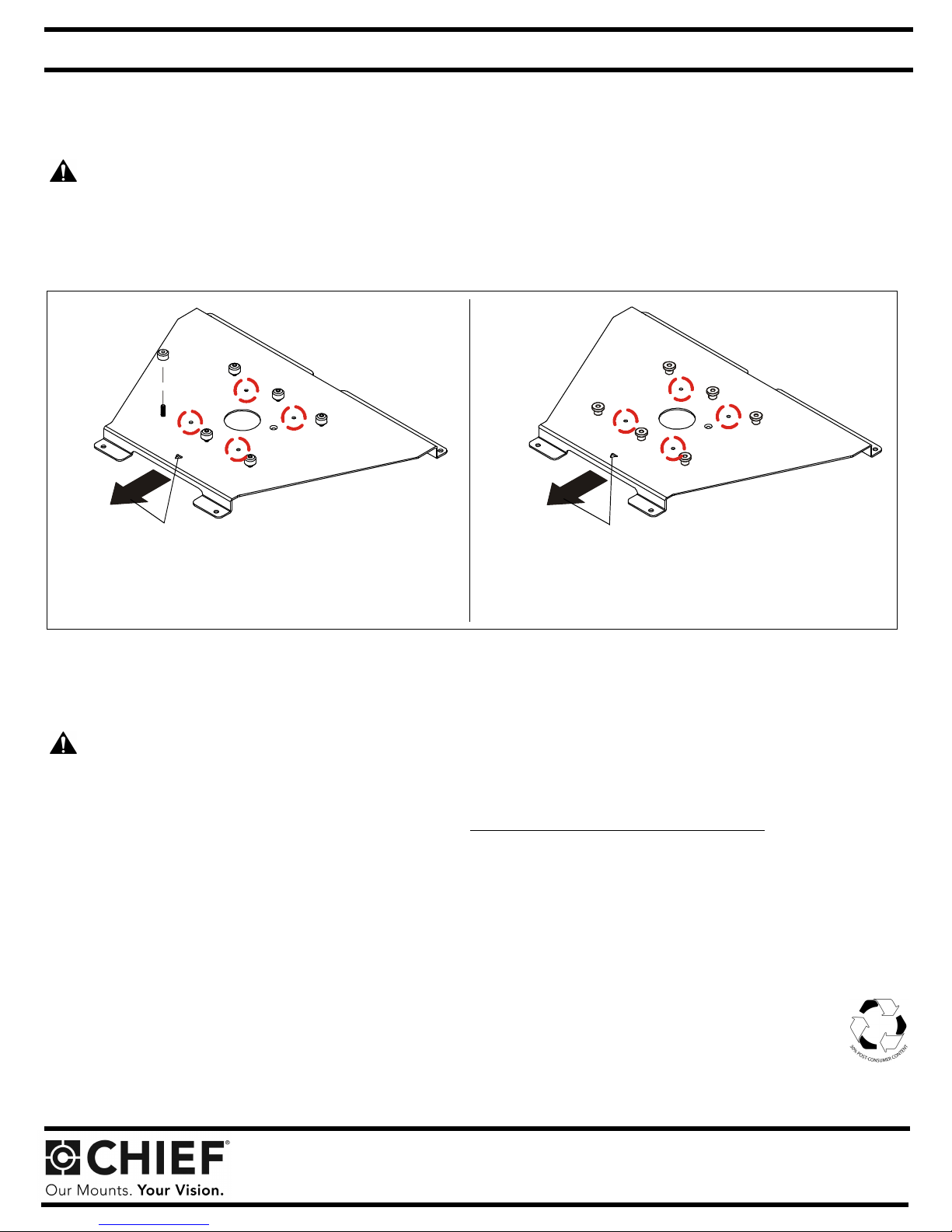
Towards fr on t
of projector
SLB-301
Note: SSB-style interface bracket connections a re circled. Note: SSM-style interface bracke t connections are circled.
**Only used when installing SLB/SSB interface brackets.
Towards front
of projector
SLM-301
NOTE: Specific to SSB-style and SSM-style interface bracket installation: All appropriate screws come pre-installed in the circled locations above.
DO NOT attempt to substitute and USE ONLY this pre-installed hardware for SSB-style and SSM-style interface bracket installation.
Installation Instructions
WARNING: OVER TIGHTENING OF SCREWS CAN DAMAGE PARTS AND CAN LEAD TO SERIOUS PERSONAL INJURY AND
DAMAGE TO EQUIPMENT! DO NOT over tighten screws when installing interface brackets.
NOTE: Step 1 is only required when installing an SLB/SSB interface bracket. If an SLM/SSM bracket is being installed, proceed to step 2.
1. Screw thumb screws onto 10-24 x 5/8" Phillips pan head screws. DO NOT fully tighten thumb screws at this time.
2. Turn projector upside down on a flat surface.
3. Place the nylon spacer onto bottom of the projector over threaded insert near center of projector.
4. Place the interface br acket onto the bot tom of the pr ojector , alig ning the mount ing hole near center of the bracket with t he spa cer and h oles
in bracket side tabs with other threaded inserts in the bottom of the projector. Ensure that triangle in bracket points towards front of
projector.
5. Position M6 x 10mm mo unting screws with M6 flat washers t hrough four holes i n bracket side tabs and into thread ed inserts in bot tom of
projector. Place the M6 x 20mm screw through the mounting hole near center of interface bracket, through nylon spacer and into the
threaded insert. Tighten all fasteners at this time, securing the bracket to the projector.
NOTE: Security screws can be substituted when mounting interface bracket to projector by using the p arts and installation
Chief® is a registered trademark of Milestone AV Technologies. All rights reserved.
instructions in the All-Points Security Kit.
Milestone AV Technologies, and its affiliated co rpo rat ions a nd s ubs id iaries (collectively, "Milestone"), intend to mak e th is ma nual ac curate and complete. However, Milestone mak es
no claim that the information contained h erein co vers all details, conditions or variations, nor does it provide for every pos sible contingency in connection with the installation or use
of this product. The information contained in this document is subject to change without notice or obligation of any kind. Milestone makes no representation of warranty, expressed or
implied, regarding the information contained herein. Milestone assumes no responsibility for accuracy, completeness or sufficiency of the information contained in this document.
Chief Manufacturing, a products division of Milestone AV Technologies
• P: 800.582.6480 / 952.225.6000 • F:877.894.6918 / 952.894.6918
6436 City West Par kway, Eden Prairie, MN 55344
©2012 Milest one AV Techn ologies,
a Duchossois Gr oup Company
8800-0 02 16 6 R ev 01
06/12
 Loading...