


Chief SLB278 Installation Guide
INSTALLATION INSTRUCTIONS
SSB-278, SSM-278, SLB-278 and SLM-278 Interface Brackets
SSB-278, SSM-278, SLB-278 and SLM-278 Interface Brackets are designed for use with Chief® Series Projector Mounts. See the specific
installation instructions provided with the mount for additional installation information.
Unpack carton and verify kit contents. If any listed parts are missing, immedia tely contact a Chief Customer Service representative.
WARNING: IMPROPER INSTALLATION CAN LEAD TO EQUIPMENT FALLING CAUSING SERIOUS PERSONAL INJURY AND
DAMAGE TO EQUIPMENT! DO NOT substitute hardware. Use only hardware supplied by manufacturer!
(1) Interface Bracket (5) Spacer, .500 x .316 x .500
(6) 10-24 Thumb Nuts ** (5) Screw, Phillips Flat Head, Machine, M4 x 25mm
(1) All-Points Security Kit (1) 5/32" Securi ty Hex Key
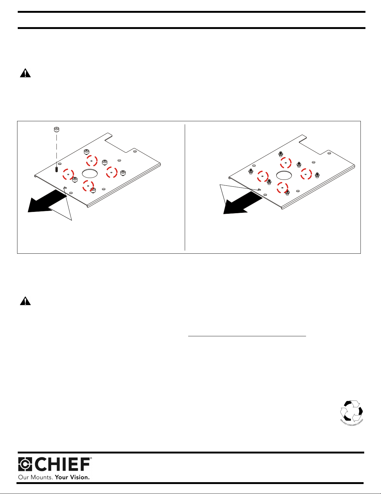
Towards front
of projector
Towards front
of projector
SLB-278
Note: SSB-style interface bracket connections are circled. Note: SSM-style interface bracket connections are circled.
**Only used when installing SLB/SSB interface brackets.
SLM-278
NOTE: Specific to SSB-style and SSM-style interface bracket installation: All appropriate screws come pre-installed in the circled locations above.
DO NOT attempt to substitute and USE ONLY this pre-installed hardware for SSB-style and SSM-style interface bracket installation.
Installation Instructions
WARNING: OVER TIGHTENING OF SCREWS CAN DAMAGE PARTS AND CAN LEAD TO SERIOUS PERSONAL INJURY AND
DAMAGE TO EQUIPMENT! DO NOT over tighten screws when installing interface brackets.
NOTE: Step 1 is only required when installing an SLB/SSB interface bracket. If an SLM/SSM bracket is being installed, proceed to step 2.
1. Screw thumb screws onto 10-24 x 5/8" Phillips pan head screws. DO NOT fully tighten thumb screws at this time.
2. Turn projector upside down on a flat surface.
3. Place five spacers onto the bottom of the projector, aligning the spacers with the threaded inserts in the projector.
4. Place the interface bracket ont o the spacer s, alignin g the mounting holes in the brac ket with the s pacers and thre aded inserts i n the bo ttom
of the projector and ensuring that triangle in bracket points towards front of projector.
5. Position M4 x 25mm mounting screws into the bracket mounting holes and threaded inserts. Tighten all fasteners at this time, securing
the bracket to the projector.
NOTE: Security screws can be substitu ted wh en mounti ng In terfa ce bracke t to proje ctor by u sin g the part s an d insta llat ion in struct ions i n the
All-Points Security Kit.
Chief® is a registered trademark of Milestone AV Technologies. All rights reserved.
Milestone AV Technologies, and its affiliated co rpo rat ions a nd s ubs id iaries (collectively, "Milestone"), intend to mak e th is ma nual ac curate and complete. However, Milestone mak es
no claim that the information contained h erein co vers all details, conditions or variations, nor does it provide for every pos sible contingency in connection with the installation or use
of this product. The information contained in this document is subject to change without notice or obligation of any kind. Milestone makes no representation of warranty, expressed or
implied, regarding the information contained herein. Milestone assumes no responsibility for accuracy, completeness or sufficiency of the information contained in this document.
Chief Manufacturing, a products division of Milestone AV Technologies
8401 Eagle Creek Parkway, Savage, MN 55378
• P: 800.582.6480 / 952.894.6280 • F:877.894.6918 / 952.894.6918
©2011 Mileston e AV Technolog ies,
a Duchossois Gr oup Company
8802-0 02 07 8 R ev 01
03/11