

Page 1
INSTALLATION
INSTRUCTIONS
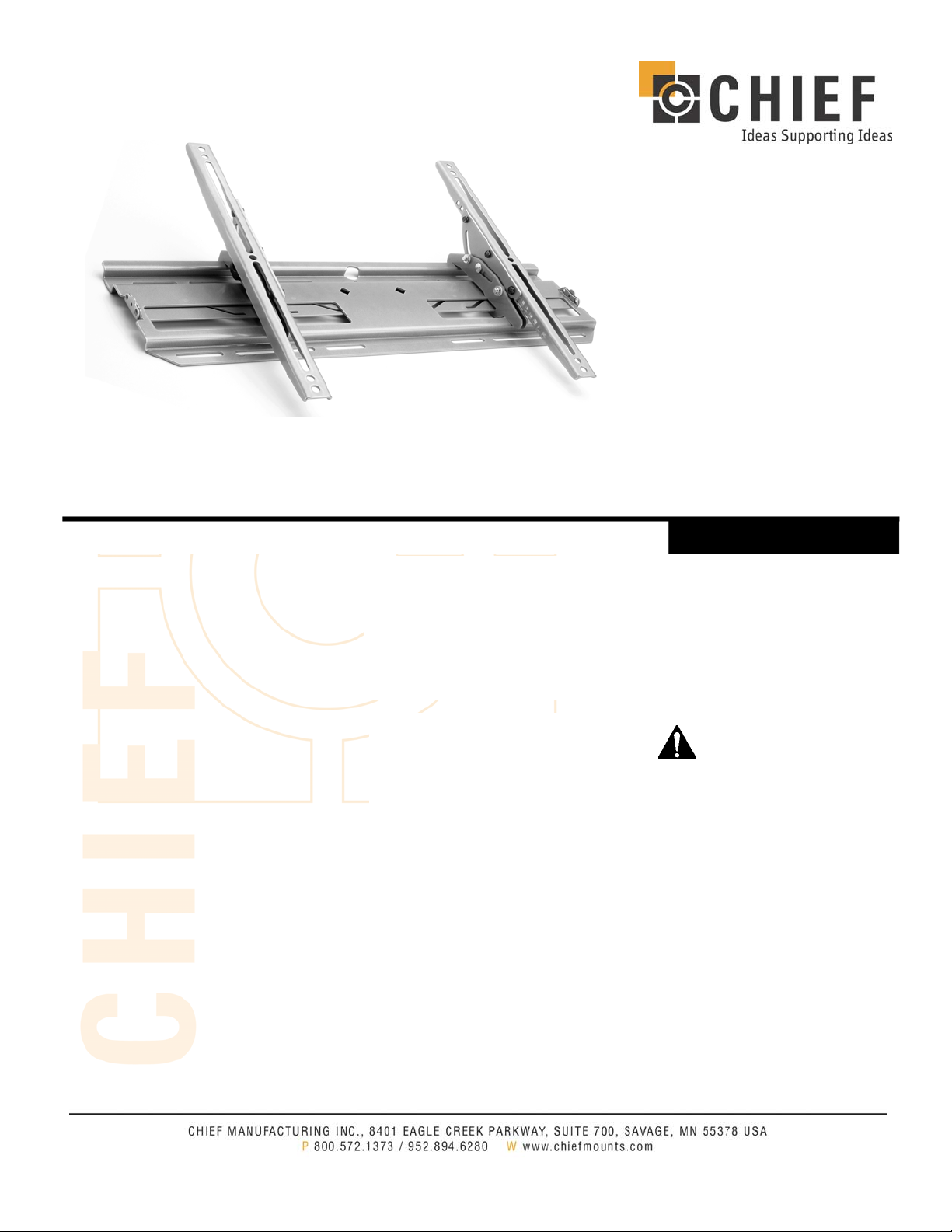
PLASMA TV WALL MOUNT
TILT Universal
(RGTU-210)
WARNINGS
WARNING
CAUTION
WARNING
WARNING
WARNING
WARNING
WARNING
WARNING
CAUTION
CAUTION
A WARNING alerts you to the possibility of serious injury or death if you do not follow
the instructions.
A CAUTION alerts you to the possibility of damage or destruction of equipment if you do
not follow the corresponding instructions.
Improper installation can result in serious personal injury! Make sure that the structural
members can support a redundant weight factor
equipment: if not, reinforce the structure before installing the RGTU.
Be aware also of the potential for personal injury or damage to the unit if it is not
adequately mounted.
The installer is responsible for verifying that the wall to which the RGTU is anchored will
safely support the combined load of all attached components or other equipment.
The weight of the display placed on the RGTU must not exceed 175 lbs. (79.38 kg), the
maximum load capacity of the RGTU.
Watch for pinch points. Do not put your fingers between m ovable parts.
Make sure the mount and brackets are correctly oriented.
CAUTION: Check the unit for shipping damage before you begin the installation.
Over-tightening adjustment bolt will cause excessive wear and may distort adjustment
components.
If you have any questions about this installation, contact Chief Manufacturing at:
1.800.582-1373 or 952.277.3901.
five times
the total weight of the
Page 2

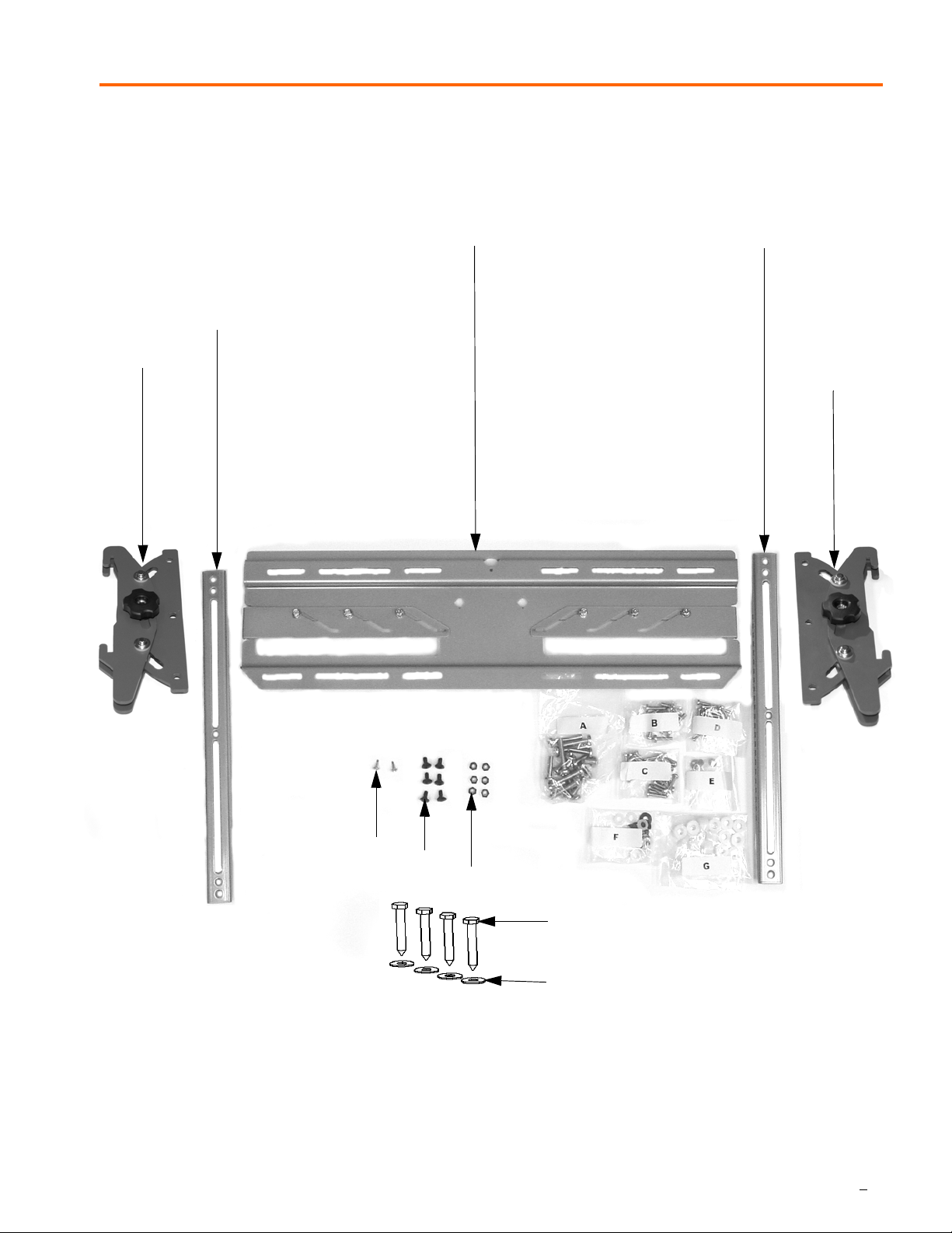
ASSEMBLY DIAGRAM
LARGE SCREEN DISPLAY MOUNT
(RGTU-210)
TOOLS REQUIRED FOR INSTALLATION
• Phillips screwdrivers, No. 1 and No. 2 TIP
• Drill and bit set
• Wrench set
NOTE: Other tools may be required depending on the
method of installation.
PARTS LIST
Table 1: Parts List
REF DESCRIPTION QTY REF DESCRIPTION QTY
10 PLATE, Wall with two latches attached 1 140 SCREW, Phillips, M4 x 20 (Parts Bag D) 8
20 BRACKET, Interface (Rt) 1 150 SCREW, Phillips, M4 x 25 (Parts Bag D) 8
30 BRACKET, Interface (Lft) 1 160 WASHER, Flat, #10 (Parts Bag E) 8
40 BRACKET, Tilt Assembly 2 170 WASHER, Flat, 1/4” (Parts Bag F) 8
50 SCREW, Phillips, M8 x 20 (Parts Bag A) 6 180 SPACER, 1/4” (Parts Bag G) 8
60 SCREW, Phillips, M8 x 30 (Parts Bag A) 6 190 SPACER, 1/2” (Parts Bag G) 8
70 SCREW, Phillips, M8 x 45 (Parts Bag A) 6 200 WASHER, Shoulder, .195”ID
(Parts Bag E)
80 SCREW, Phillips, M6 x 25 (Parts Bag B) 8 210 WASHER, Shoulder, .320”ID
(Parts Bag F)
90 SCREW, Phillips, M6 x 16 (Parts Bag B) 8 220 SCREW, Self-Tapping 2
100 SCREW, Phillips, M5 x 16 (Parts Bag C) 8 230 BOLT, Carriage, 1/4-20 x 1/2” 6
110 SCREW, Phillips, M5 x 20 (Parts Bag C) 8 240 NUT, Nylock, 1/4-20 6
120 SCREW, Phillips, M5 x 25 (Parts Bag C) 8 250 BOLT, Lag, 5/16” 4
130 SCREW, Phillips, M4 x 16 (Parts Bag D) 8 260 WASHER, 5/16” 4
8
8
2
Page 3
ASSEMBLY DIAGRAM
LARGE SCREEN DISPLAY MOUNT
PARTS
30
40
(RGTU-210)
10
20
40
220
230
240
Figure 1. Parts
250
260
3
Page 4

INSTALLATION
INSTRUCTIONS
INSPECT THE MOUNT BEFORE ASSEMBLY
1. Carefully inspect the mount for shipping damage (see
Figure 1). If any damage is apparent, call your carrier claims
agent and do not continue with the installation until the carrier
has reviewed the damage.
NOTE: Read all assembly instructions before starting
assembly.
2. Carefully inspect mount components for damage.
INSTALL INTERFACE BRACKETS
ON DISPLAY
Install the interface brackets as follows:
1. Place the interface brackets (20 and 30) on the back of
the display, aligning one of the holes or top of the slots as
a reference point to align horizontally with the square
holes facing toward the center of the display (see
Figure 2 and Figure 3).
Figure 2. Place Brackets on Display
NOTE: Spacers (180 or 190) are used to offset the
bracket if the mounting holes are recessed or to get
around the protrusions.
2. Secure the left and right factory assembled interface
bracket assemblies (20 and 30) to the display. Select the
mounting hardware that fits your application. Read the
following list and refer to Figure 4 and Figure 5.
• Use spacers (180 or 190), if necessary.
• Use M6 screws (80 or 90) or M8 screws (50, 60, or
70), steel washers (170), and shoulder washers
(210).
• Or, use M4 screws (130, 140, or 150) or M5 screws
(100, 110, or 120) steel washers (160), and shoulder washers (200).
Figure 3. Align Holes
Figure 4. Attachment Parts
4
Figure 5. Attachment
Page 5

INSTALLATION
3.Find the center line of the display (see Figure 6).
4. Using six bolts (230) and six Nylock nuts (240), attach the
tilt brackets (40) with the center hole of the tilt assembly
as close to the center line of the display as possible (see
Figure 7), positioning the assembly with the knob side
toward the outside of the display.
INSTRUCTIONS
NOTE:
Dimensions shown are
for example only
Figure 6. Center Line of Display
Figure 7. Attach Tilt Brackets
5
Page 6

INSTALLATION
INSTRUCTIONS
INSTALL WALL PLATE
Install the wall plate as follows:
WARNING: It is the responsibility of the installer to verify that
the structure to which the mount is anchored will
safely support five times the combined load of all
attached components and equipment.
1. Determine suitable a mounting location and lift the wall
plate (10) into place (see Figure 8).
2. Using a small nail or screw (not provided) in the center
hole, lightly hold wall plate at the mounting location (see
Figure 9).
3. Level the wall plate (10) and drill pilot holes for anchoring
the wall plate. If drilling into wood studs, use a 15/64” drill
bit.
4. Using four 5/16” lag bolts (250) and 5/16” washers (260),
install the wall plate on the wall.
5. Slide the latches to the outside (see Figure 10).
Figure 8. Wall Plate Dimensions
Figure 9. Wall Plate Installation
6
Figure 10. Slide Latches Outward
Page 7

INSTALLATION
INSTRUCTIONS
INSTALL DISPLAY
Install the display as follows:
1. Place the display on the wall plate (10) by hooking the
hooks of the brackets (20 and 30) in the top of the wall
plate (see Figure 11 and Figure 12).
2. Secure the display by sliding the latches, one on each
side, inward (see Figure 13).
3. If desired, install self tapping screws (220) and/or padlocks (not provided) for additional security (see Figure
14).
Figure 11. Hooks On Top (View 1)
Figure 13. Slide Latches In
Figure 14. Added Security
Figure 12. Hooks On Top (View 2)
7
Page 8

PART NO. 8805-000069 (Rev.B)
07/04
 Loading...