

Page 1
INSTALLATION INSTRUCTIONS
Plasma Wall Swing-Out (PWS)
Wall Mount
The PWS wall mount is a rugged, versatile, and installer-friendly
solution to unique display mounting requirements. This instruction
manual contains instructions for Model PWS2000.
With the PWS securely mounted on a wall, simply hang your display
like a picture (vertical or horizontal). Using the Q-latch mounting system permits you to hang and secure your display quickly.
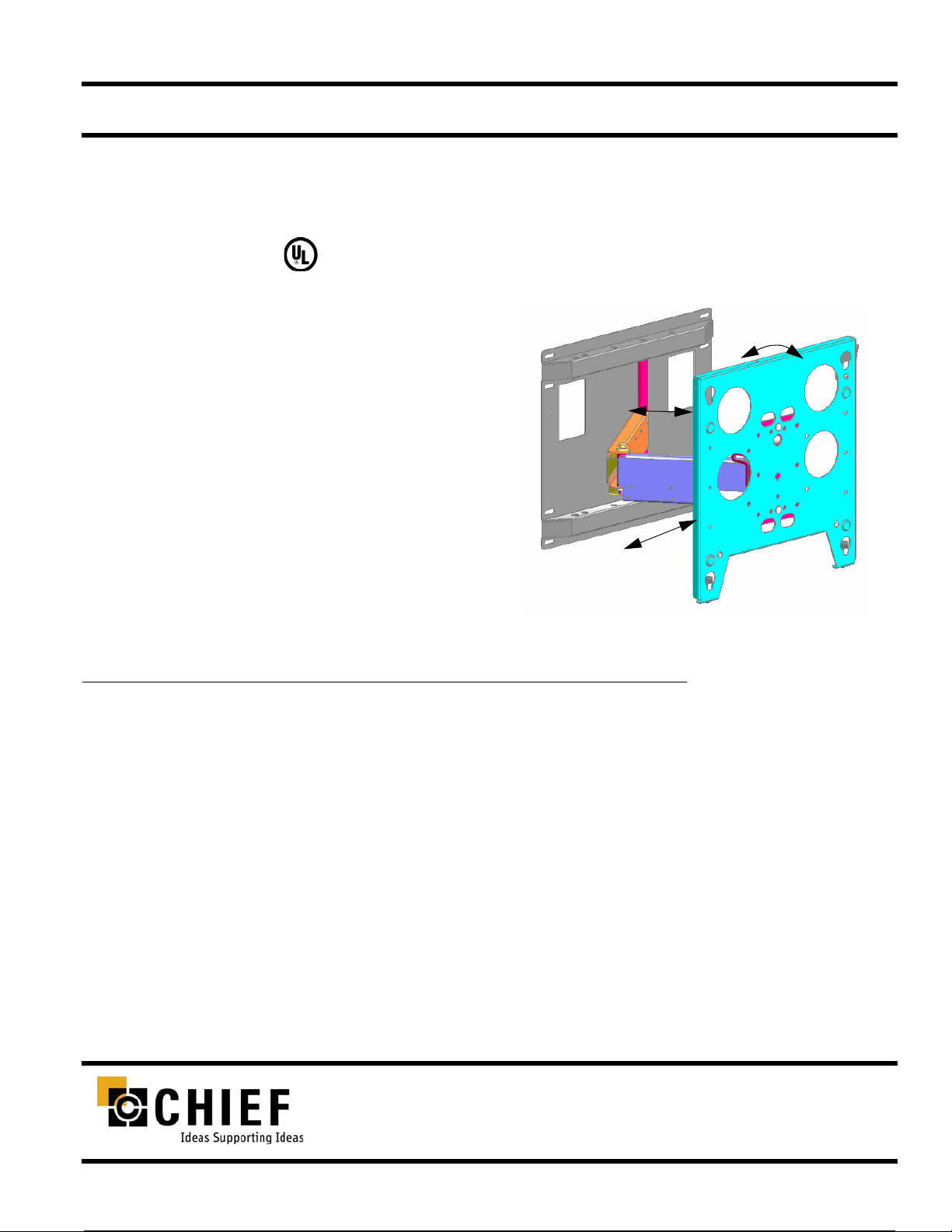
The PWS allows you pull your display out 23.5” from the wall, pivot
it up to 90 degrees left or right of center, traverse up to 22” left or
right of center, and adjust the pitch 5 degrees up and 15 degrees down.
The PWS also provides 2 degrees roll adjustment right and left for
screen leveling.
T wo electrical box openings in the wall plate is provided for cabling.
The cable tray hides cables for aesthetics and cable protection.
BEFORE YOU BEGIN
• Caution: To prevent damage to the PWS, which could affect or void the Factory warranty, and to the equipment that
will be attached to it, thoroughly study all instructions and illustrations before you begin the installation. Pay particular attention to the “Important Warnings and Precautions” on Page 1.
• The maximum weight to be installed on the PWS wall mount is 100 pounds (45.36Kg).
• The PWS wall mount is designed to be installed using wall studs or supporting framework. The wall to which the PWS wall
mount is anchored must be capable of supporting four times the total weight of the mount and all attached equipment.
• If you have any questions about this installation, contact Chief Manufacturing at 1-800-582-6480.
CHIEF MANUFACTURING INC.
1-800-582-6480 952-894-6280 FAX 952-894-6918
8401 EAGLE CREEK PARKWAY, STE. 700
SAVAGE, MINNESOTA 55378 USA
PART NO. 8831-000003 (Rev. H)
©2000 Chief Manufacturing
www.chiefmfg.com
11-04
Page 2

Installation Instructions PWS
IMPORTANT WARNINGS AND PRECAUTIONS!
WARN ING: A WARN ING alerts you to the possibility of serious injury or death if you do not follow the instructions.
CAUTION: A CAUTION alerts you to the possibility of damage or destruction of equipment if you do not follow the corre-
sponding instructions.
• WARNING:Improper installation can r esult in serious personal injury! Make sure that the structural members can
support a redundant weight factor four times the total weight of the equipment: if not, reinforce the structure before installing the PWS.
• WARN ING: Be aware also of the potential for personal injury or damage to the unit if it is not adequately mounted.
• WARN ING: The installer is responsible for verifying that the wall, to which the PWS is anchored, will safely support
the combined load of all attached components or other equipment.
• WARNING:The weight of the display placed on the PWS must not exceed 100 lbs. (45.36 kg), the maximum load
capacity of the PWS.
• WARN ING: Watch for pinch points. Do not put your fingers between movable parts.
• CAUTION: Check the unit for shipping damage before you begin the installation.
NOTE: Hardware for attaching this unit to the wall is not supplied.
TOOLS REQUIRED FOR INSTALLATION
• Electric drill and bit set
• Socket set with extension and open wrenches
NOTE: Other tools may be required depending on the
method of installing the mount on the wall.
CONTENTS
DIMENSIONAL DRAWING ........................................ 2
INSPECT THE UNIT BEFORE INSTALLING ............ 3
PWS INSTALLATION ..................................... .... ... ... . 3
MOUNT THE DISPLAY ............ ... ... ... .... .................... 5
ADJUSTMENTS ........................................................ 4
Rotational Adjustment ......................................................... 4
Pitch Adjustment ................................................................. 4
Horizontal Adjustment ........................................................ 4
REMOVE THE DISPLAY ........................................... 4
1
Page 3
Installation Instructions PWS
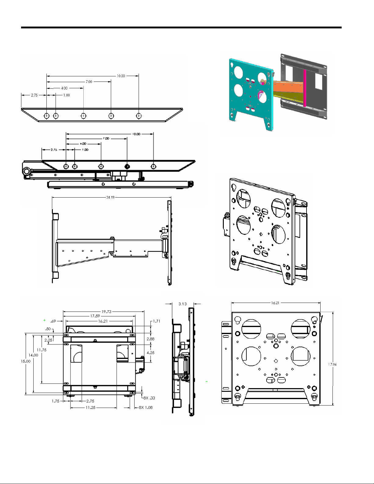
DIMENSIONAL DRAWING
PWS Backing Plate Dimensions
2
Page 4

Installation Instructions PWS
INSPECT THE UNIT BEFORE INSTALLING
WARNING: Watch for pinch points. Do not put your fingers
between movable parts.
1. Carefully inspect the PWS for shipping damage. If any damage
is apparent, call your carrier claims agent and do not continue
with the installation until the carrier has reviewed the damage.
NOTE: Read all instructions before starting installation.
2. Lay out components to ensure you have all the required parts
before proceeding:
1 PWS (see PWS dimensional drawing on page 2)
PWS INSTALLATION
WARNING: It is the responsibility of the installer to verify that
the wall to which the PWS is anchored will safely
support the combined load of all attached components and equipment.
CAUTION: DO NOT attempt to mount the Flat Panel Display in
an inverted position. Mounting the Flat Panel Display
in an inverted position may cause overheating and
extensive damage to the Flat Panel Display.
Install the PWS as follows:
1. Determine the exact mounting location prior to installation,
considering the unit’s total swing arm radius.
2. Using the wall plate as a pattern, transfer the mounting hole
pattern to the wall.
NOTE: Notice the wall plate has a nominal hole (2”X4”) to
accommodate a duplex wall outlet.
3. Drill pilot holes at the desired height.
WARNING: Improper installation can result in serious per-
sonal injury! Make sure that the structural members can support a redundant weight factor five
times the total weight of the equipment: if not,
reinforce the structure before installing the PWS.
4. With the PWS correctly oriented and level, secure the PWS to
the wall using a minimum of four fasteners (not included). Fasteners must be driven into the supporting wall studs or other
supporting framework.
3
Page 5
Installation Instructions PWS
MOUNT THE DISPLAY
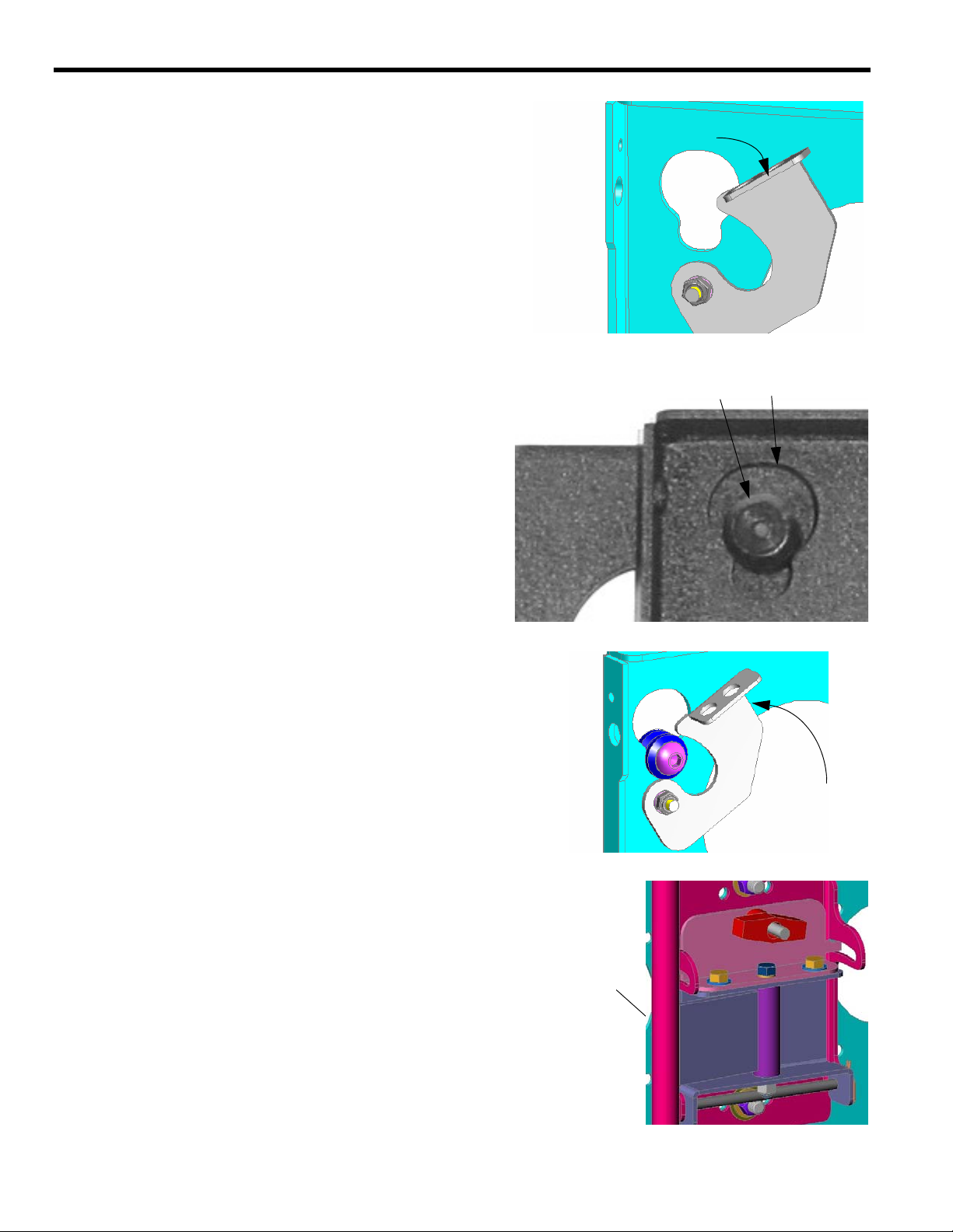
Make sure latching flag is lowered
WARNING: Watch for pinch points. Do not put your fingers
between movable parts.
1. For Model PWS2000 only , follow the instructions for installing
the PSB bracket(s) of your specific flat panel display.
2. Before lifting your flat panel display , make sure the latch of the
PWS is lowered and will not interfere with mounting the display (see Figure 1).
3. Using two people, align the Q-latch buttons with the Q-latch
openings and install the display. Make sure the buttons of the
Q-latch bracket fully engage all the Q-latch openings on the
PWS (see Figure 2).
4. Secure the display to the PWS by completely engaging the
latch (see Figure 3).
5. Connect and secure power/audio/video cables, making sure to
leave sufficient slack to allow for movement of the swing arms.
FIGURE 1. LOWER LATCH
Q-latch Button
Q-latch Opening
ADJUSTMENTS
Rotational Adjustment
1. If necessary, loosen or tighten bottom rotational tilt tension
adjustment nut (see Figure 4).
2. Mount the display and check for desired rotational tilt tension.
3. Repeat Steps 1 and 2 until desired rotational tilt tension is
obtained.
Pitch Adjustment
1. Turn the T-knob handle until desired angle is achieved.
2. Make sure the carriage bolt is properly seated.
Horizontal Adjustment
1. Turn the display to desired horizontal position (max. 90
degrees).
2. Pull display from wall or push display back to wall.
REMOVE THE DISPLAY
Back of Display
PWS
FIGURE 2. ENGAGE Q-LATCH
PWS
Raise latch
Back of Display
FIGURE 3. RAISE LATCH
1. Disconnect power/audio/video cables.
2. Disengage (lower) the latch.
3. Using two people, lift the display from the PWS.
4
Adjust Rotation
FIGURE 7. ADJUST ROTATION
 Loading...