

Page 1
INSTALLATION INSTRUCTIONS
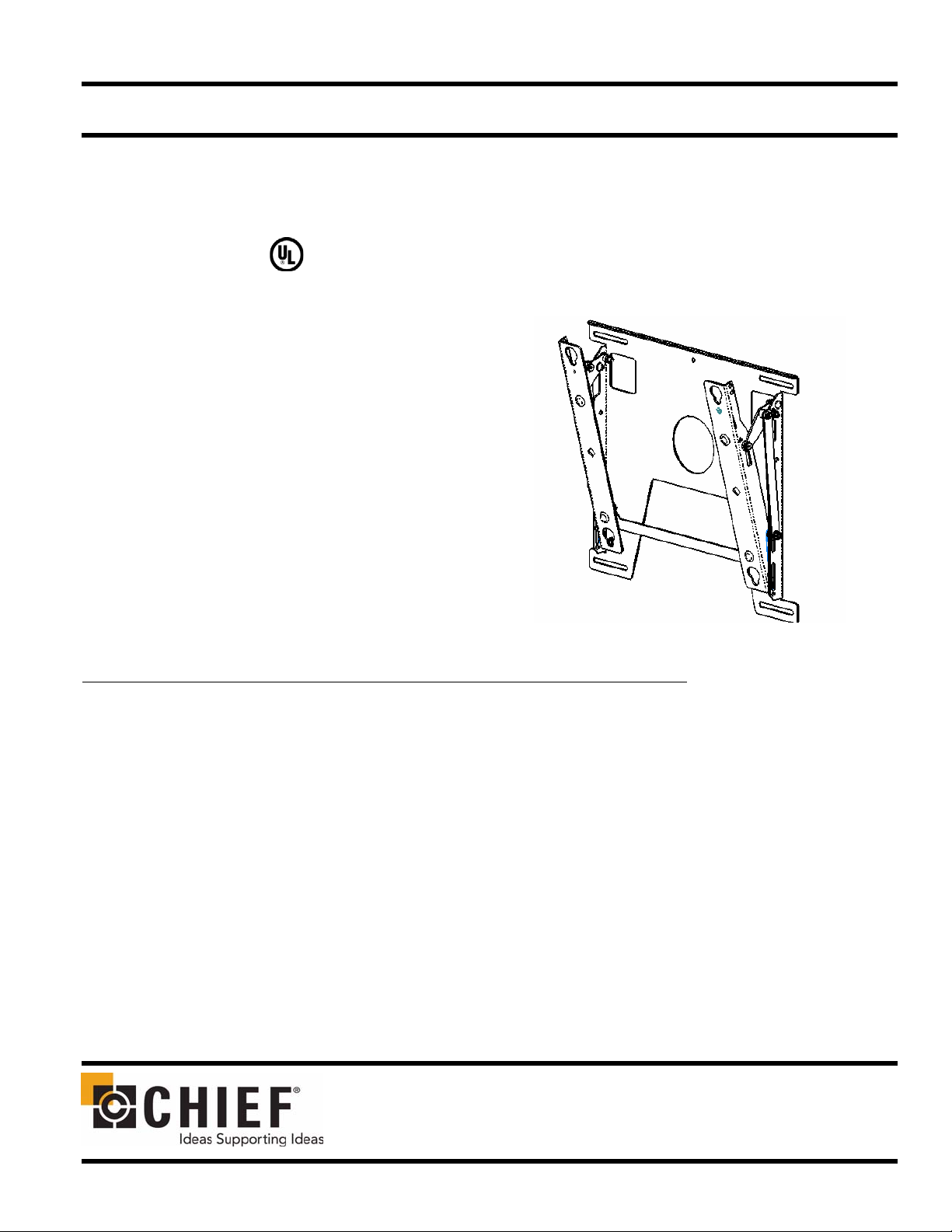
Plasma Low Profile (PLP Series)
Wall Mount
The PLP wall mount is a quick disconnect mounting system with a
pitch adjustment range between 0 and 15 degrees. The mount can be
adjusted to accomodate the weight of different plasma screens. The
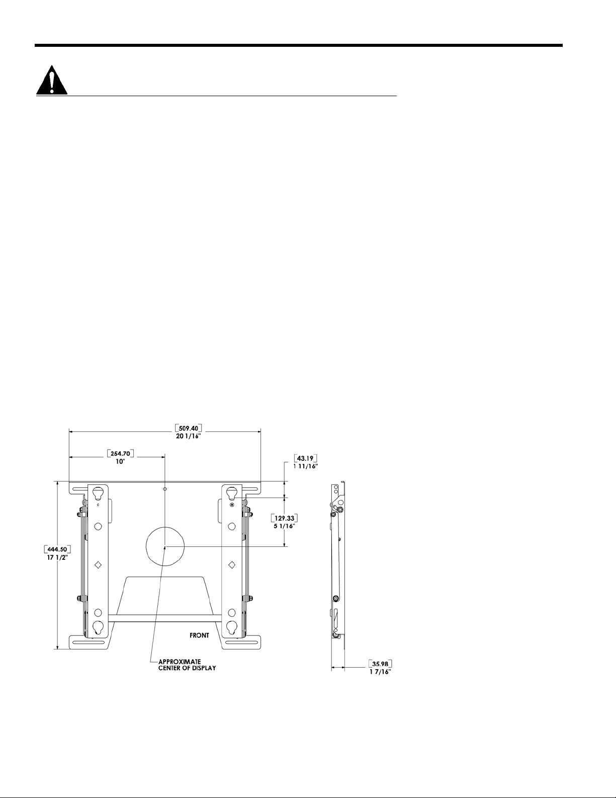
mount is approximately 1-7/16” deep in the retracted position.
Once the brackets are attached to the plasma screen, simply mount the
PLP securely on a wall, lock the plasma screen in place using the convenient locking flag, and attach the audio/video cables. The bottom
of the PLP pulls forward 3” and locks in place, allowing easy access
for cable attachment.
The PLP is hidden behind the plasma screen, making it a low profile
wall mount.
BEFORE YOU BEGIN
• Caution: To prevent damage to the PLP, which could affect or void the Factory warranty, and to the equipment that
will be attached to it, thoroughly study all instructions and illustrations before you begin the installation. Pay particular attention to the “Important Warnings and Cautions” on Page 2.
• The maximum weight to be installed on the PLP wall mount is 150 lbs (68.04 Kg).
• If you have any questions about this installation, contact Chief Manufacturing at 1-800-582-6480.
NOTE: This manual (8805-000125) supersedes manual 8804-000005.
CHIEF MANUFACTURING INC.
1-800-582-6480 952-894-6280 FAX 952-894-6918
8401 EAGLE CREEK PARKWAY, STE. 700
SAVAGE, MINNESOTA 55378 USA
PART NO. 8805-000125 (Rev. A)
2005 Chief Manufacturing
www.chiefmfg.com
04/05
Page 2
Installation Instructions PLP Series
IMPORTANT WARNINGS AND CAUTIONS!
WARNING: A WARNING alerts you to the possibility of serious injury or death if you do not follow the instructions.
CAUTION: A CAUTION alerts you to the possibility of damage or destruction of equipment if you do not follow the corre-
sponding instructions.
• WARNING: Improper installation can result in serious personal injury! Make sure that the structural members can
support a redundant weight factor five times the total weight of the equipment: if not, reinforce the structure before installing the PLP.
• WARNING: Be aware also of the potential for personal injury or damage to the unit if it is not adequately mounted.
• WARNING: The installer is responsible for verifying that the wall to which the PLP is anchored will safely support the
combined load of all attached components or other equipment.
• WARNING: The weight of the PLP display must not exceed 150 lbs. (68.04 kg), the maximum load capacity of the PLP.
• WARNING: Watch for pinch points. Do not put your fingers between movable parts.
• WARNING: Make sure the mount and brackets are correctly oriented (tabs down, 16” apart).
• WARNING: Make sure the flag securing the display is completely lowered at all times except when removing or install-
ing the display. The flag must be all the way down when installing/removing cables.
• CAUTION: Check the unit for shipping damage before you begin the installation.
NOTE
THE CUSTOM INTERFACE BRACKET IS NOT
SHOWN. THE CUSTOM INTERFACE BRACKET
NEEDED FOR YOUR DISPLAY WILL ADD
BETWEEN 1/2” AND 2” IN DEPTH AND MAY
AFFECT LOCATION OF DISPLAY OF THE
MOUNT.
Dimensional Drawing
2
Page 3
Installation Instructions PLP Series
PLP ASSEMBLY
WARNING: The PLP must be installed with correct end,
indicated by “Mount This Side Up”, on top.
WARNING: It is the responsibility of the installer to verify
that the wall to which the PLP is anchored will
safety support the combined load of all
attached components and equipment.
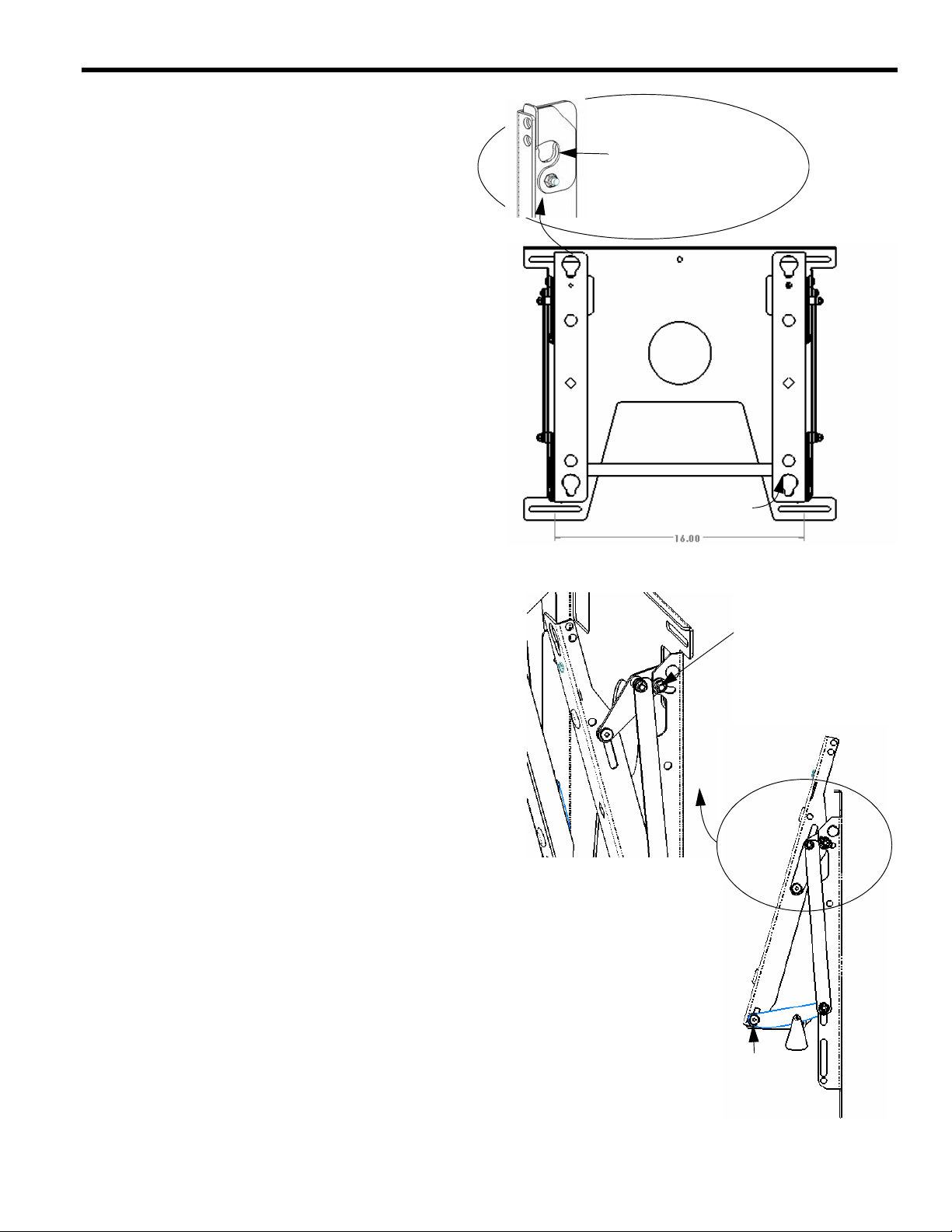
With the PLP correctly oriented (Mount This Side Up) and
level, secure the PLP to the wall using a minimum of four
fasteners (not included). Fasteners must be driven into the
supporting wall studs or other supporting framework.
Mount the Display
1. Make sure no power is supplied to the display and the flag
is in the up position before attempting to mount the display.
2. Using two people, slide the display down over the PLP.
Make sure all four Quick Latches (Q-Latches) of the display engage all four slots in the PLP.
3. With the Q-Latches of the display fully engaged in the
slots of the PLP, secure the display on the PLP by lowering
the flag all the way down to the locked position. If the flag
does not fully engage, remove the display and make sure
the brackets are correctly installed.
Optional Security Lock Here
Center Support Bar
Front View
Tighten bolt on
each sideto secure
display angle
NOTE: A security lock may be installed through the hole in the
flag for additional security.
NOTE: If display does not remain at desired tilt setting, tighten
the bolt on the tilt arm on each side.
WARNING: Make sure the flag securing the display is com-
pletely lowered at all times except when
removing or installing the display. The flag
must be all the way down when installing/
removing cables.
4. If necessary, pull the bottom of the display up and out to
install power/audio/video cables. Lower the two latches to
prevent the display from moving back, making sure the
safety bar lowers into to secure the latches.
WARNING:Watch for pinch points. Do not put your fin-
gers between movable parts.
5. Raise and lower latches (A) by raising and lowering the
center support bar, being careful not to pinch fingers,
return the bottom of the display.
A
Side View
3
Page 4
Installation Instructions PLP Series
Remove the Display
WARNING: Make sure the flag securing the display is com-
pletely lowered at all times except when
removing or installing the display. The flag
must be all the way down when installing/
removing cables.
1. If necessary, pull the bottom of the display up and out,
lower latches by lowering the center support bar and disconnect all power/audio/video cables.
WARNING:Watch for pinch points. Do not put your fin-
gers between movable parts.
2. Pull the bottom of the display up and out slightly, raise
latches by raising the center support bar and. being careful
not to pinch fingers, return the bottom of the display.
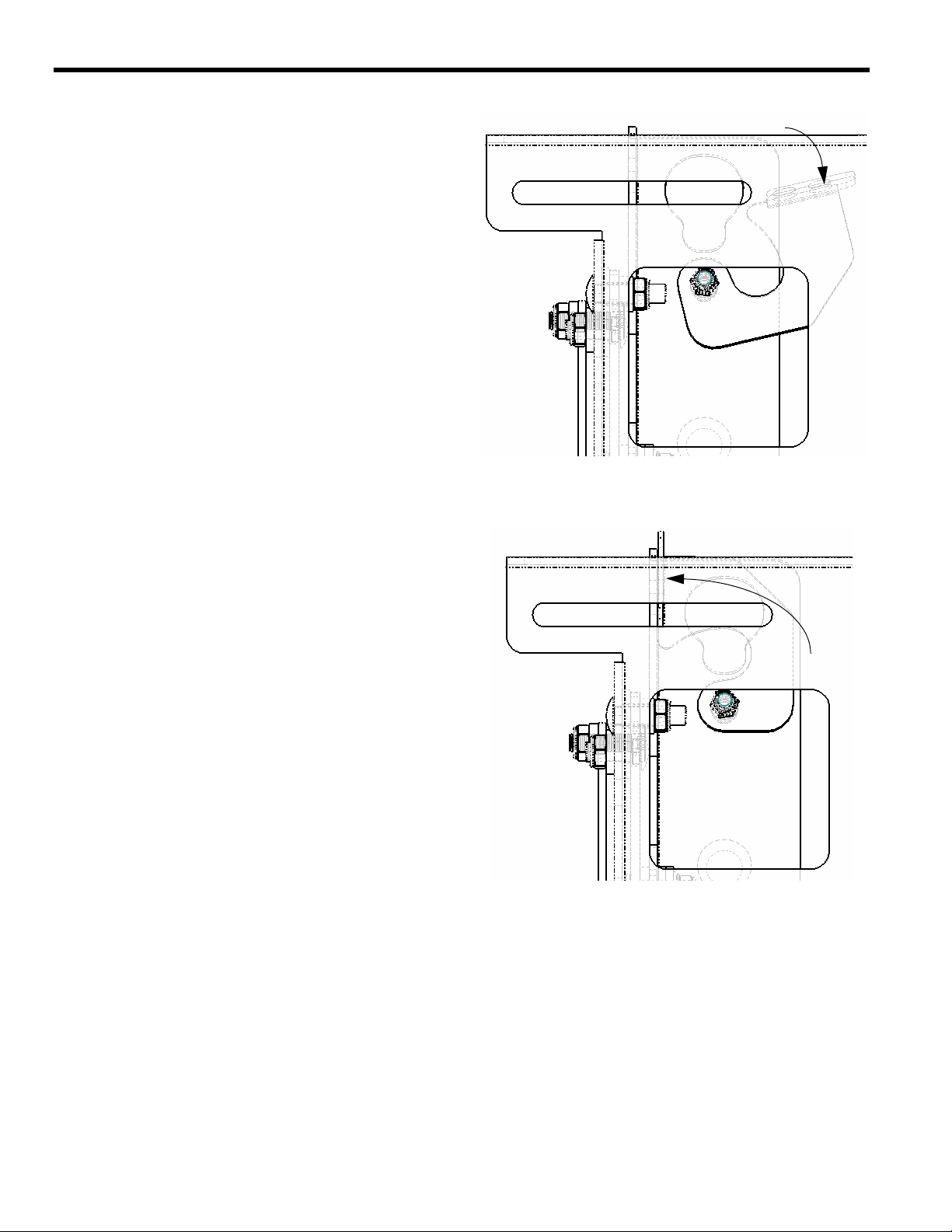
3. Unlock the display from the PLP by raising the flag all the
way up to the unlocked position.
Unlocks the display
4. Using two people, slide the display up and out of the PLP.
Unlock Display
Locks the display
Lock Display
4
 Loading...