

Page 1

PIT BOSS
Users Manual
2008 © Chief Automotive Technologies.
Page 2

PIT BOSS
Users Manual
CHIEF’S LIMITED ONE-YEAR
WARRANTY & LIABILITY
Chief Automotive Technologies warrants for one year from date of installation and/or
purchase any components of its Pit Boss Lift system, which do not perform satisfactorily
due to defect caused by faulty material or workmanship. Chief’s obligation under this
warranty is limited to the repair or replacement of products which are defective and
which have not been misused, carelessly handled, or defaced by repair or repairs made
or attempted by others.
CHIEF AUTOMOTIVE TECHNOLOGIES DOES NOT ASSUME RESPONSIBILITY
FOR ANY DEATH, INJURY OR PROPERTY DAMAGE RESULTING FROM THE
OPERATOR’S NEGLIGENCE OR MISUSE OF THIS PRODUCT OR ITS
ATTACHMENTS. CHIEF MAKES NO WRITTEN, EXPRESS OR IMPLIED
WARRANTY WHATSOEVER OF MERCHANTABILITY OR FITNESS FOR A
PARTICULAR PURPOSE OR OTHERWISE REGARDING THE EQUIPMENT OR
ANY PART OF THE PRODUCT OTHER THAN THE LIMITED ONE-YEAR
WARRANTY STATED ABOVE.
Page 3
PIT BOSS
Users Manual
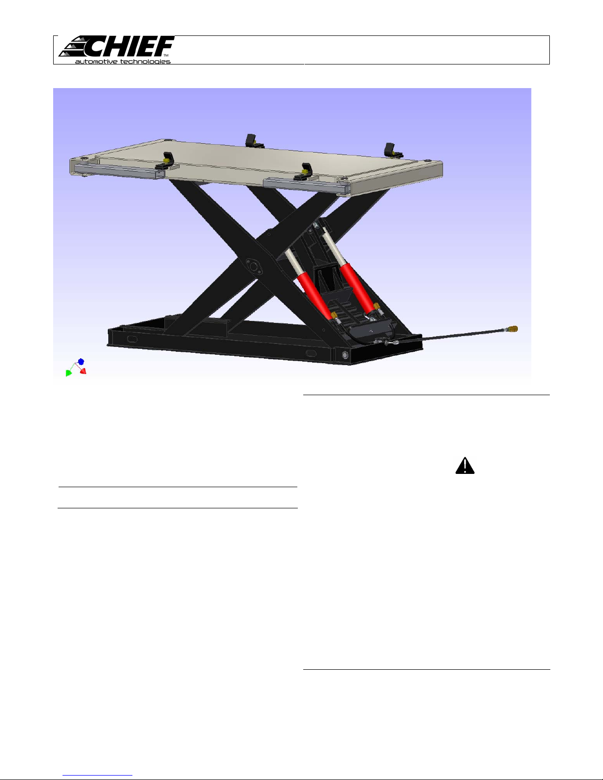
This owner’s manual is written to familiarize operators with
the safe and efficient operation of the Chief PIT BOSS lift
system. The PIT BOSS lift features Shop Hopper and
vehicle lifting capabilities.
The lift is hydraulically positioned at various working heights
suitable to the operator.
NOTE:
This manual is not intended to replace Chief Automotive
training. For information concerning training, contact Chief
Automotive Technologies.
Illustrations shown in this manual
may vary slightly from actual product
IMPORTANT:
1. DO NOT attempt to operate the Chief PIT BOSS
without first reading this entire manual.
2. Complete safety information is highlighted throughout
this manual and is identified by:
3. This safety alert symbol identifies safety information.
Operator injury could result if these CAUTION notes
are not followed.
4. Qualified service personnel must check operational
capacity of the PIT BOSS lift system prior to its initial
use and at intervals of no more than one year. Contact
your authorized Chief Automotive Technologies
representative for inspection.
5. Persons operating the PIT BOSS lift must be at least
18 years of age, must be trained in the operation of the
PIT BOSS lift, and must have demonstrated their
qualifications to the employer. They must also be
specifically assigned to operate the PIT BOSS lift by
the employer and this assignment must be in writing.
1
Page 4

IMPORTANT SAFETY INSTRUCTIONS
When using your garage equipment, basic safety precautions should always be
followed, including the following:
1. Read all instructions.
Care must be taken as burns can occur from touching hot parts.
2.
Do not operate equipment with a damaged hose or if the equipment has been
3.
dropped or damaged – until it has been examined by a qualified service person.
Do not let a hose hang over the ledge of the table, bench, or counter or come in
4.
contact with hot manifolds or moving fan blades.
5. Care should be taken to arrange the hose so that it will not be tripped over or
pulled.
Always unplug equipment from the air supply when not in use.
6.
7. Loop hose loosely around pump stand when storing.
To reduce the risk of fire, do not operate equipment in the vicinity of open
8.
containers of flammable liquids (gasoline).
9. Keep hair, loose clothing, fingers and all parts of the body away from moving
PIT BOSS
Users Manual
parts.
To reduce the risk of electric shock, do not use on wet surfaces or expose to rain.
10.
Use only as described in this manual. Use only manufacturer’s recommended
11.
attachments.
ALWAYS WEAR SAFETY GLASSES. Everyday eyeglasses only have impact
12.
resistant lenses, they are not safety glasses.
2
Page 5
PIT BOSS
Users Manual
General Safety Tips
General
DO NOT operate this machine unless:
1. You are authorized in writing by your
2. All towers are properly secured to machine.
3. Vehicle’s wheels are blocked and parking
4. Load is 8500 lbs or less.
5. Field of motion of load carrying device is free
Persons operating the PIT BOSS lift must be at
least 18 years of age, must be trained in the
operation of the PIT BOSS lift, and must have
demonstrated their qualifications to the employer.
DO NOT attempt to operate the PIT BOSS lift
without first reading this entire manual.
Always wear safety glasses when using the PIT
BOSS lift or any of its accessories.
Maintain a free space of 20 inches (50cm)
minimum around all moving parts and pinch points
on machine.
Collar
To avoid accidental dropping of tower collar,
tighten collar locking knob and/or lower collar to
bottom of tower.
Collar locking knob must be tightened before
removing tower chain from vehicle.
employer.
brake is set.
of persons and obstructions.
Tower Movement
Fully engage tower leg into Shop-Hopper
receptacle to prevent tower movement during the
pull or during a raising or lowering procedure.
When pushing tower, keep both hands on tower
levers. Also, keep hands away from all pinch
points.
NOTE: The hose and pump will need to be stowed
when moving towers around the shop.
Pulling
To Prevent personal injury from flying objects:
• Check all bolts, nuts, and clamps for
• Deformed or elongated materials must be
• If materials look deformed, they are deformed.
Remove twist in chain before applying pressure to
chain.
Raise / Lower Machine
When raising or lowering the PIT BOSS lift, be
certain to secure the Shop-Hopper to the lift top.
The clamps must firmly engage the tube holes.
Lifting of persons is prohibited.
Keep feet and objects clear of mainframe when
lowering machine.
To avoid severe personal injury to yourself and
others: DO NOT position yourself close to, or inline with chains, clamps, or other accessories
while pressure is applied to this system.
deformation or elongation prior to each use.
replaced.
Replace them.
WARNING!
WARNING!
3
Page 6
Raise / Lower Machine (continued)
To avoid personal injury or damage to equipment
before operating the machine, make sure:
Persons and objects are clear of machine.
Hoses and other objects are free of the lift legs
Oil spills must be cleaned up immediately to
prevent slipping. Hoses on the floor can create a
tripping hazard.
Loading / Unloading Machine
DO NOT run over air hoses or hydraulic lines when
loading or unloading vehicles.
DO NOT exceed the machine’s 8500 lbs. (3850 kg)
lifting capacity.
Shop Hopper
To avoid injury, always use an assistant when
lifting and positioning anchoring crossbars.
When making heavy pulls, tie the anchoring bases
back to the deck using a chain and turnbuckle
assist.
Keep loads centered.
Always have assistance when moving shop
hopper.
Avoid sloped surfaces whenever possible.
If a sloped surface must be crossed, use extreme
caution and always roll straight up and down the
slope, NEVER sideways to it.
Always apply wheel brakes when parked.
During docking, entire perimeter of Shop-Hopper is
a potential pinch point. Take care when raising and
lowering the deck to load and unload the Shop
Hopper.
PIT BOSS
Chain
The 3/8” tower chain is proof tested to 20,000 lbs.
(90kN).
To avoid personal injury or damage to property, DO
NOT:
• Heat chain or hook while repairing vehicle.
600 8F (316 8C) of heat on chain will weaken
it.
• Tip load chain hook
• Pull with twisted chain links
Hydraulics
Keep pump away from excessive heat or flames.
The surrounding temperature should not exceed
122° F (508 C).
Always release hydraulic pressure before
disconnecting hydraulic hoses.
If pump fails to shut off, disconnect air supply and
contact an authorized Chief Automotive
Technologies service representative.
All components must be replaced with Chief
Automotive Technologies authorized replacement
parts.
Improper handling and/or modification of parts is
forbidden and may cause a hazardous situation for
the user. Such action immediately voids the
warranty and releases the manufacturer from all
liability.
Keep pump in upright position. DO NOT lay pump
on its side.
Fill pump reservoir with all cylinders. (see
maintenance section).
DO NOT overfill pump reservoir.
Operational Capacity
Qualified service personnel must check operational
capacity of the PIT BOSS lift prior to its initial use
and at intervals of no more than one year. Contact
your authorized Chief Automotive Technologies
representative for inspection.
Optional Steps / Ladders
Use only approved steps and ladders when
working on or around this equipment.
Users Manual
4
Page 7
Hydraulic System Components
General
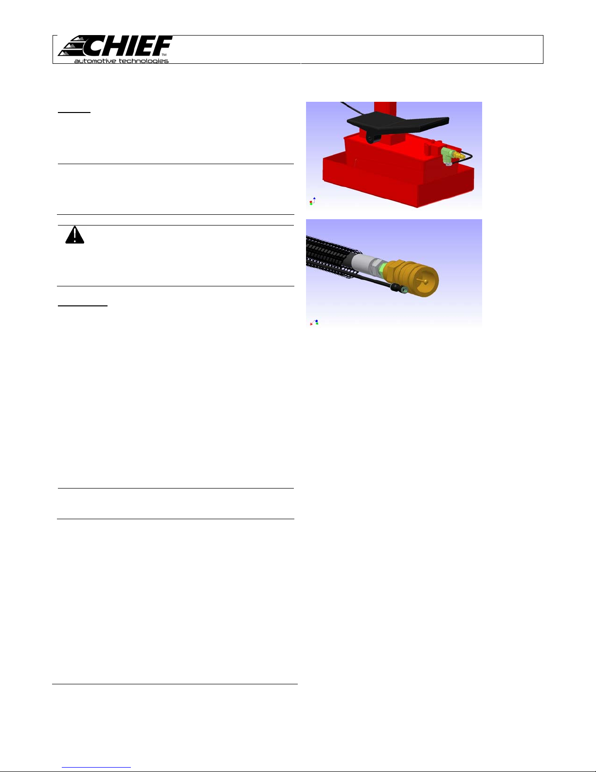
The Chief PIT BOSS is powered by a pneumatically
operated hydraulic pump, which is operated by a foot
pedal(see Figure 1)
Initial Setup
The PIT BOSS lift requires a compressed air supply to
activate the safety lock releases. Before using the PIT
BOSS, it is necessary to install a customer supplied air
coupler. The PIT BOSS lift pump is equipped with a ¼”
Female NPT port on the back. (See figure 1)
The PIT BOSS lift pump must be connected to the hydraulic
hose at the end of the lift. First connect hydraulic quick
coupler (see Figure 2). Be certain the locking ring is
completely tightened. Read the next section on pump
usage then lift the PIT BOSS lift to its highest position.
Press the down lever on the pump until the PIT BOSS lift
completely settles into the top locking height. Connect the
pneumatic line from the pump to the coupler on the PIT
BOSS. (To connect a pneumatic line, firmly push the hose
into the fitting until it is fully seated.)
NOTE:
WARNING:
IMPORTANT:
The PIT BOSS lift has a high
pressure hydraulic system, it builds
hydraulic pressure quickly. Be aware
of this quick reaction when making
pulls or lifting vehicles.
To avoid personal injury or damage
to property: When disconnecting
hydraulic quick couplers, some fluid
spillage may occur. Always clean up
any hydraulic fluid spillage from floor
or work area.
When connecting hoses, check for
any interference of lines with moving
parts.
PIT BOSS
Users Manual
Figure 1
Figure 2
5
Page 8
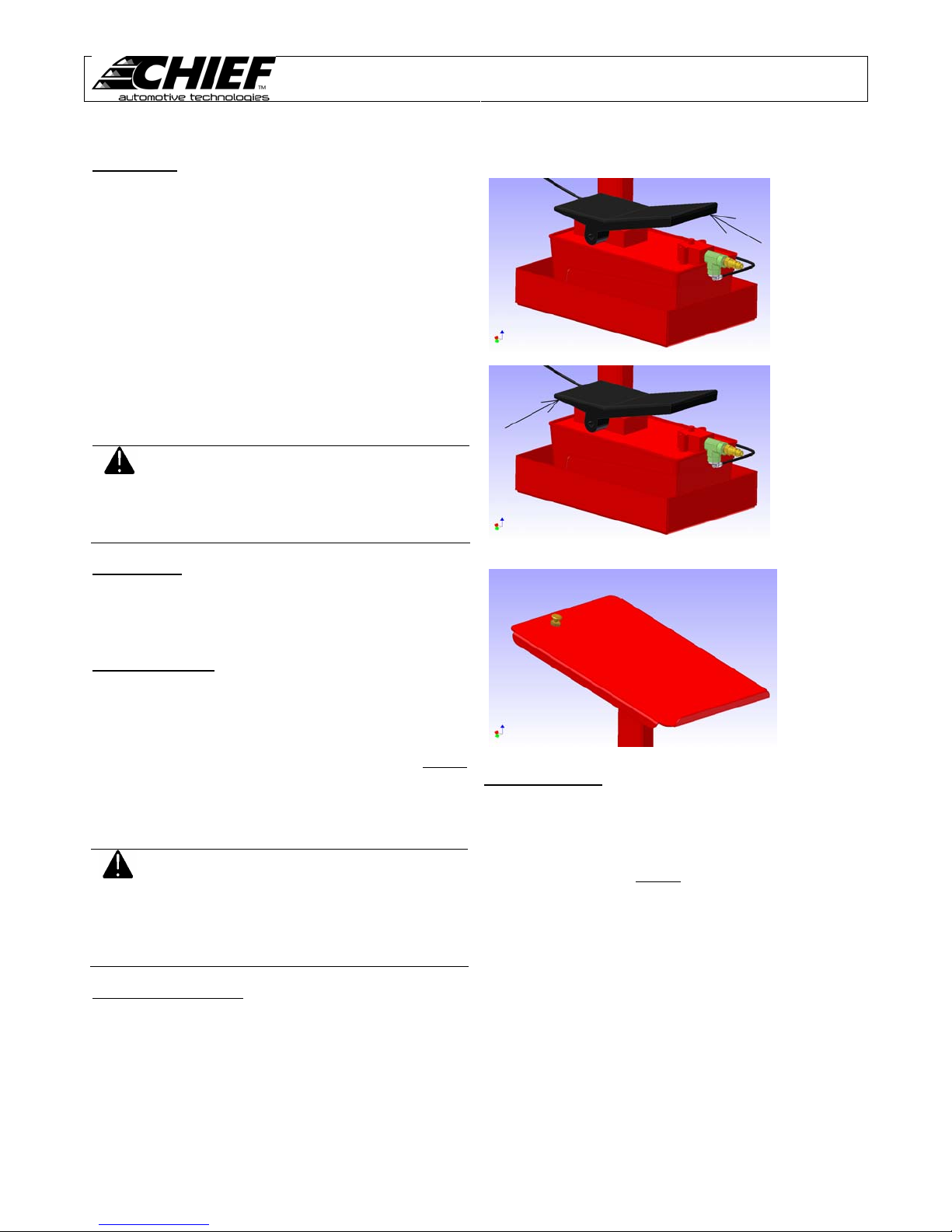
Pump Usage
To activate hydraulic pump and apply pressure to s ystem to
raise machine, depress the up pedal on the foot pump (Se e
figure 3). The pump will build hydraulic pressure in the
system to activate lift cylinders.
To disengage the hydraulic pump, release the foot pedal on
the pump. This action stops the flow of hydraulic oil to the
system being operated: however, the system holds existing
hydraulic pressure.
To release hydraulic pressure, depress the down pedal of
the foot pump. (See figure 4). This will release the
hydraulic pressure in the system and return hydraulic oil to
the pump reservoir.
Lock Release
The lock release is a pneumatic valve that must be press ed
to deactivate the lock arm and lower the Pit Boss (see
Figure 5).
To Lower Machine
1. Activate lock arm release by depressing and holding the
brass button on the pump stand. (See figure 5)
2. Depr ess and hold the “UP” pedal on the foot pump to
raise the machine until the safety lock arm audibly
releases from its lock position. (See figure 3)
3. While continuing to hold down the “UNLOCK” button,
depress and hold the “DOWN” pedal on the foot pump.
Adjust Working Height
The PIT BOSS lift has six (6) working heights from 9 inches
(480 mm) to 45 inches (1220 mm).
CAUTION:
CAUTION:
To prevent damage to the pump and
hydraulic cylinders, DO NOT operate
pump when cylinders are fully
extended. (If possible, stop
supplying pressure before cylinders
reach full extension)
• Before lowering machine, clear
all obstacles from under and
around machine.
• DO NOT allow anyone or
anything to ride on machine or
be under machine during
lowering procedures.
PIT BOSS
Users Manual
Figure 3
Figure 4
Figure 5
To Raise Machine
1. Activate pump by depressing and holding “UP” pedal on
pump.
2. After machine is slightly above desired working height,
as indicated by the audible
locking position, release “UP” pedal on the pump.
3. Depr ess and hold “DOWN” pedal on the pu mp to lower
machine into mechanical stops.
drop of the lock arm into its
6
Page 9
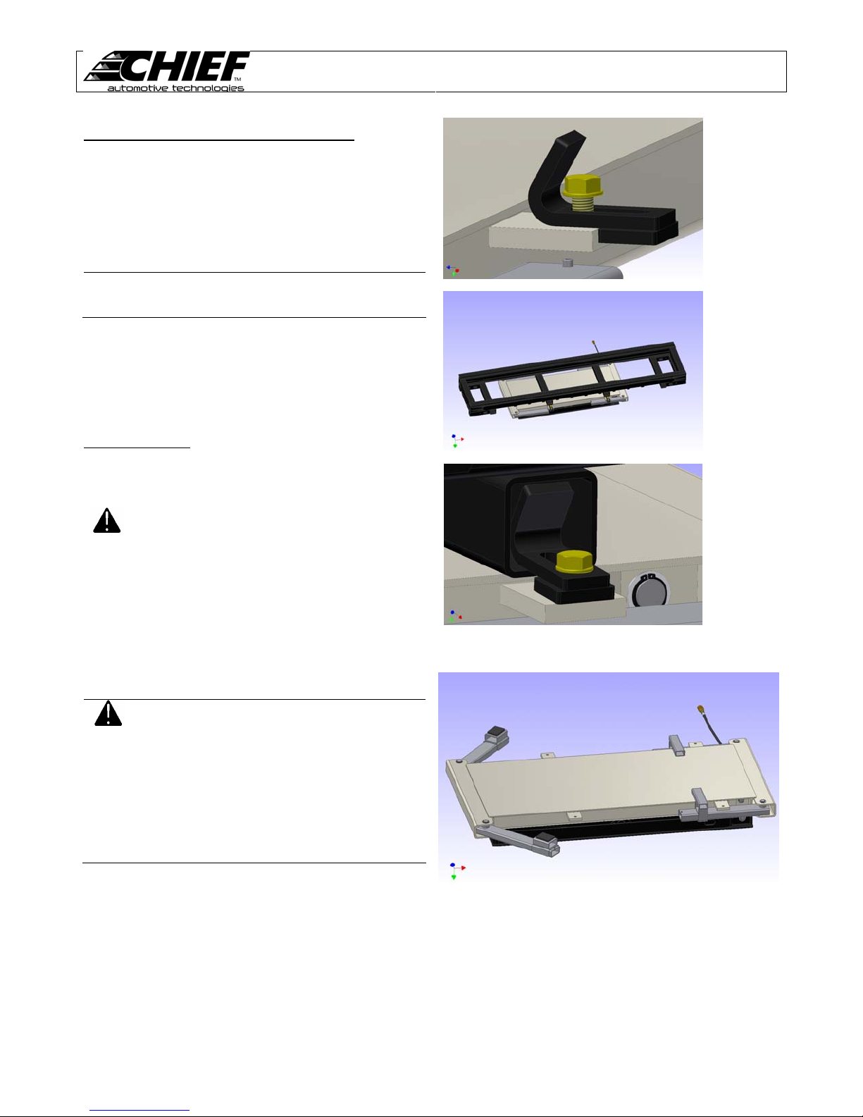
Docking the Shop-Hopper with the PIT BOSS
1. Retract the mounting clamps on the PIT BOSS and
remove any frame adapters from the lift arms (see
Figure 6).
2. Position the Shop-Hopper over the PIT BOSS and
align the square holes of the center tubes with the
mounting clamps (see Figure 7).
NOTE:
3. Raise the PIT BOSS until the Shop-Hopper fully sits on
the flat of the lift.
4. Slide the mounting clamps fully into the sq uare tubes
of the Shop-Hopper and tighten with a 30mm wrench
(see Figure 8)
Loading a vehicle
When loading a vehicle on to the PIT BOSS lift observe the
following precautions.
If the PIT BOSS is not mounted with the table
top flush with the floor the Shop-Hopper must
dock on the lift from the side.
CAUTION:
• When driving or winching vehi cle
on or off machine, use a helper
to guide.
• When positioning a vehicle over
the lift the vehicle should be
centered over the lift from side to
side as closely as possible.
• The center of gravity of the
vehicle should be as close to the
center of the lift as possible.
• DO NOT exceed 8500 lbs. Lifting
capacity of PIT BOSS lift.
PIT BOSS
Users Manual
Figure 6
Figure 7
Figure 8
CAUTION:
• Before raising lift, verify that all
lift pads securely mate to a
suitable lifting point on the
vehicle.
• If the frame of the vehicle is too
narrow for the lift arms use the
offset arm mounts.
• ONLY USE THE OFFSET ARM
MOUNTS WITH THE ARMS
FULLY RETRACTED SEE
FIGURE 9
Figure 9
7
Page 10
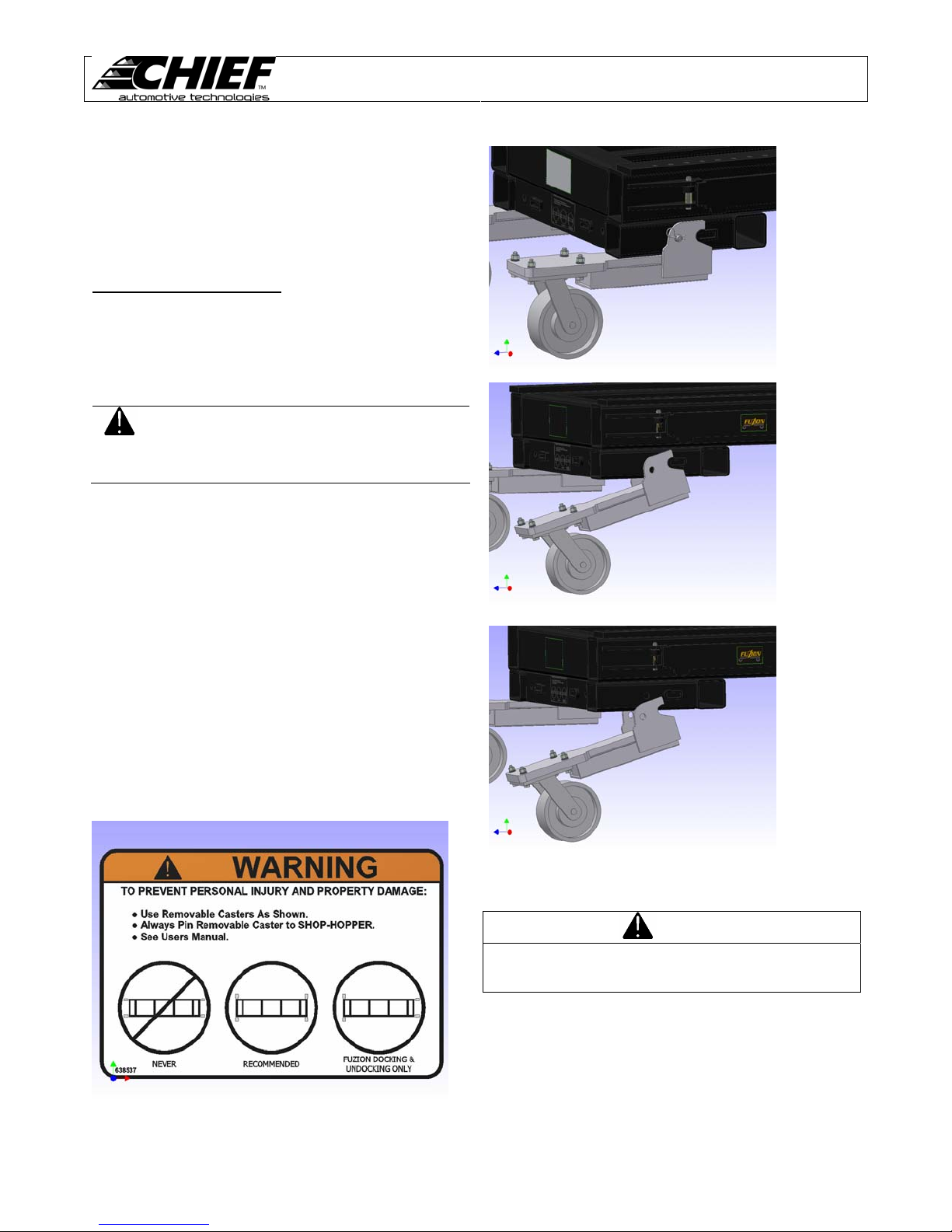
Shop-Hopper Removable Casters
The removable casters of the Shop-Hopper give three
primary benefits. First, they allow the Shop-Hopper to be
docked with the Fuzion at both ends. Second, they allow
the Fuzion to be lowered into the lowest position with the
Shop-Hopper docked. Third, they allow the Shop-Hopper t o
sit on the floor when removed.
Removable Caster Mounting
The removable casters can be mounted from the ends and
from the sides at both ends of the Shop-Hopper. For normal
use all casters should always be mounted from the sides for
maximum stability. Mounting one pair from the end and th e
other pair from the side allows the Shop-Hopper to be
docked with the Fuzion.
To prevent personal injury or
WARNING:
To remove the casters the Shop-Hopper must first be raised
at least 4 inches. Next, lock the swivel lock mechanism on
the caster to be removed. Third, remove the hair pin clip
from the retaining pin. (See figure 10) Then slightly lift the
caster end of the mount and remove the pin at the same
time. With the pin removed the mount will pivot down. (See
figure 11) Continue to pivot the mount down and unhook
the mount from the lock. The mount will then slide freely
from the Shop-Hopper. (See figure 12)
To install the casters, the Shop-Hopper must be lifted at
least 16” off the floor. Installation is similar to removal with
some additional steps. First, determine the most likely use
of the Shop-Hopper. If it is to be docked with the Fuzion,
pick which end will be to the front of the Fuzion. That end
will have to have the casters mounted from the end. If the
Shop-Hopper is not likely to be docked, all casters should be
mounted from the side for maximum stability. (See figure 13)
After this has been done, the casters can be installed at the
appropriate locations.
property damage never mount both
pairs of casters from the ends of the
Shop-Hopper. (See figure 13)
PIT BOSS
Users Manual
Figure 10
Figure 11
Figure 13
Figure 12
WARNING
To prevent personal injury and property damage. A lways
fully engage the pin and hair pin clip when installing the
casters.
8
Page 11
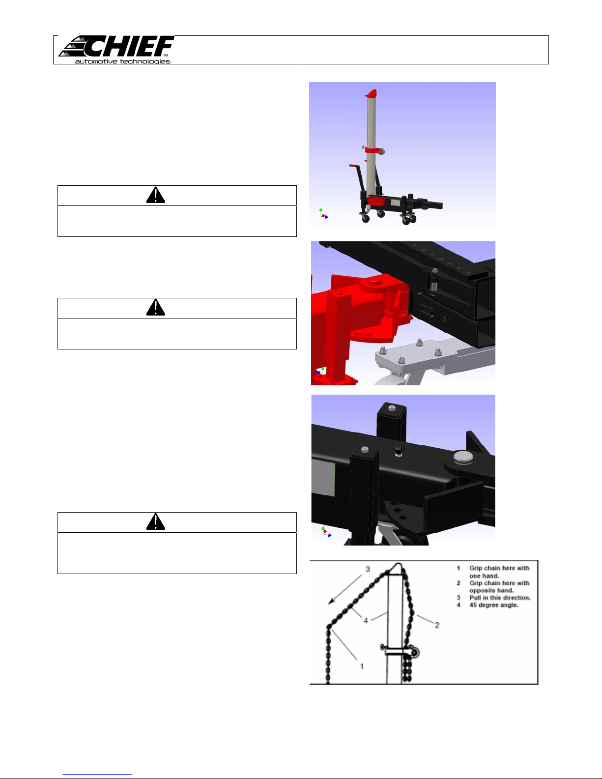
Shop-Hopper Tower
The Shop-Hopper tower is an optional accessory that allo ws
light pulls to be done with the Shop-Hopper. (See figure 14)
This tower mates to any of the 12 square holes around the
bottom of the Shop-Hopper. In order to properly use the
Shop-Hopper tower, the tower must be fully inserted into
one of the square holes. (See figure 15)
WARNING
To prevent personal injury and property damage. A lways
fully engage the Shop-Hopper tower mount into the
Shop-Hopper before making any pulls.
While the Shop-Hopper is on the PIT BOSS it is permissible
to use one of the center square holes as a tower location.
Remove only one hold down clamp and insert the tower into
that location if needed.
WARNING
To prevent personal injury and property damage. A lways
replace the hold down clamp removed when finished with
the pull.
Once engaged into the Shop-Hopper, the tower may be
pivoted in the mount to achieve the desired pulling angle.
To do this, lift the spring loaded pull pin on the tower arm.
(See figure 16) Next, rotate the tower and full y engage the
pull pin into the desired location.
The Shop-Hopper tower is hydraulically powered by an air
over hydraulic pump similar to the PIT BOSS. The pump
must be connected to an air supply to function.
The vertical angle of the pull is controlled by adjusting the up
and down position of the tower collar on the tower pipe. The
horizontal angle of the pull is adjusted by to wer placement
and the rotation of the tower collar on the tower pipe.
PIT BOSS
Users Manual
Figure 14
Figure 15
WARNING
To prevent personal injury and property damage. Never
lower the PIT BOSS below the normal ride height of
the Shop-Hopper Tower with the tower engaged into the
Shop-Hopper.
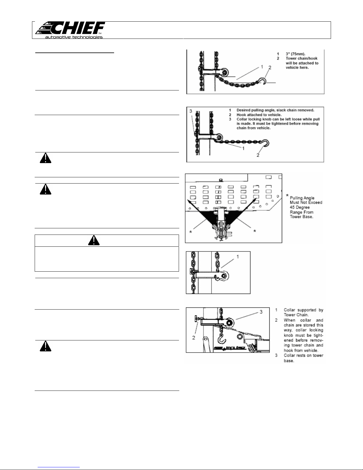
1. To adjust slack to wer chain, grip chain on each side of
tower. Lift out on tail of chain until it is approximately 45
degrees from tower. Then disengage chain from tower
head and pull chain to either increase or decrease
amount of slack. (see figure 17)
2. Support collar with one hand while loosening collar
locking knob with opposite hand. Then position collar
approximately three inches (75 mm) above desired
pulling height and retighten collar locking knob. (see
figure 18)
Figure 16
Figure 17
9
Page 12
To Operate Towers (continued)
3. Let tower chain h ang free momentarily to remove twist.
Then without twisting chain, attach hook to vehicle. Pull
on tail end of chain to remove slack (see figure 19).
Loosen collar locking knob and lower collar.
IMPORTANT:
4. Attach pump’s hydraulic hos e to tower quick coupler at
the base of the tower pipe.
5. To operate pump, follow usage procedures on page 8.
CAUTION:
CAUTION:
Remove twist from chain before
lowering collar. Make sure that chain
links between collar roller and hook
align.
To prevent damage to tower
assembly, pulls must not exceed a 45
degree angle from tower base. (see
figure 20)
To avoid personal injury or damage
to equipment, DO NOT:
• Heat chain hook while repairing
• Tip load chain hook.
• Pull with twisted chain links.
vehicle. 600 8F (316 8C) of heat
on chain will weaken it.
PIT BOSS
Users Manual
Figure 18
Figure 19
WARNING
To avoid severe personal injury to yourself and others:
DO NOT position yourself close to or in-line with the
chains, clamps, or other accessories while pressure is
applied to this system.
IMPORTANT:
When tower is no longer needed, remove tower chain an d
hook from vehicle, and store collar using one of the two
methods shown in figures 21 & 22.
CAUTION:
• DO NOT tighten collar locking
knob while pressure is applied to
the system because it will be
impossible to loosen the knob
without pressure on the system.
• Collar locking knob must be
tightened before removing tower
chain and hook from vehicle.
• Collar locking knob must be tight
when collar is not in use.
• Store collar at bottom of tower
pipe or support collar with tower
chain.
Figure 20
Figures 21 & 22
10
Page 13
Shop-Hopper Vehicle Anchoring
The Shop-Hopper vehicle anchoring system consists of four
anchoring stands with clamp bars and two cross bars.
Together with the cross bars, the anchoring stands and
clamp bars provide a positive means of securing a vehicle to
the Shop-Hopper.
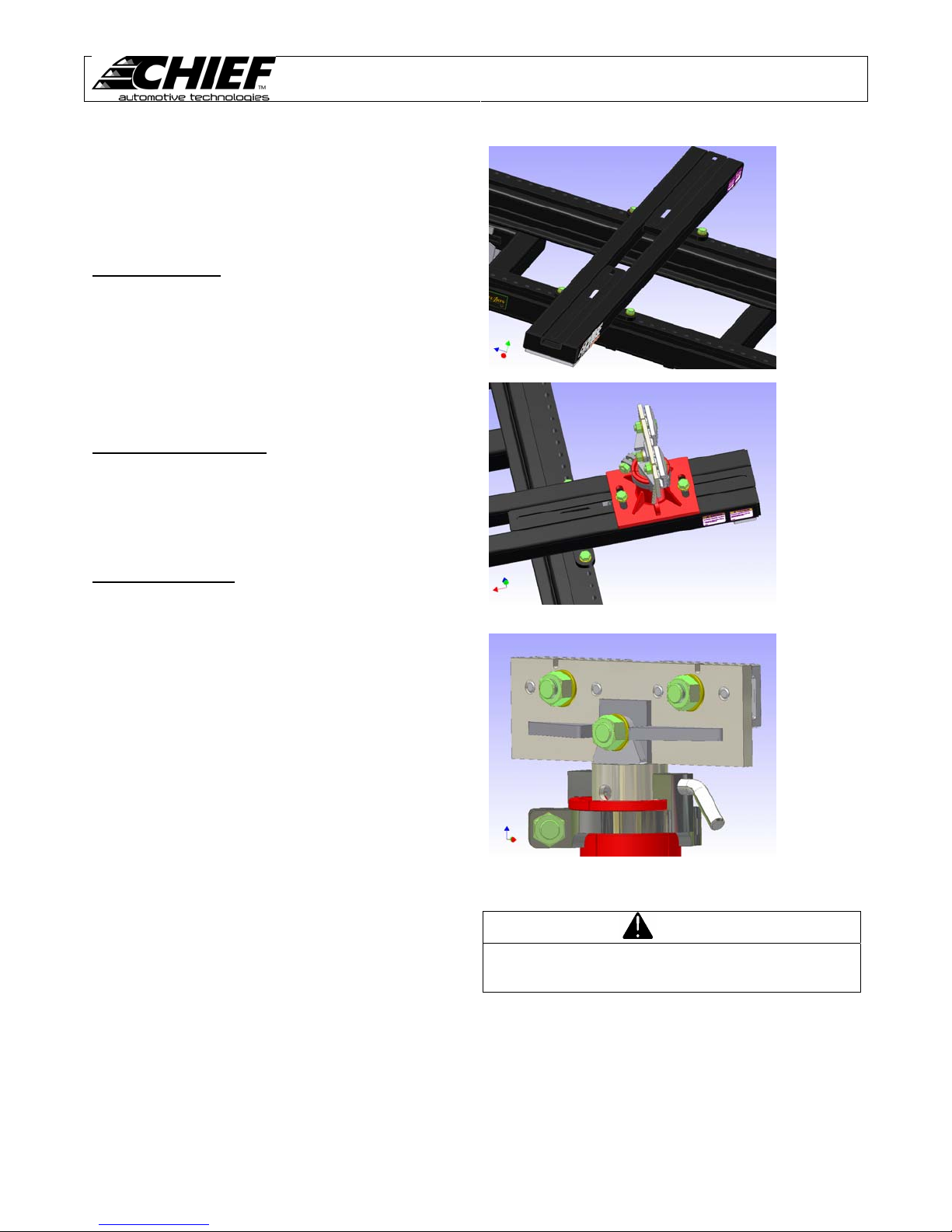
Crossbar Mounting
The crossbars can be mounted anywhere along the
Shop-Hopper as needed for the vehicle mounting locations.
Each crossbar has four bolt locations that must be used to
securely mount to the Shop-Hopper. (See figure 23) For
easier alignment of the crossbars with the desired holes,
use one of the pins from the anchoring stands as an
alignment tool. Once the crossbars have been placed,
firmly tighten the bolts with a 30mm wrench.
Anchoring Base Mounting
The anchoring stands are mounted to the crossbars. They
can be mounted anywhere along the track that the bar will
slide. (See figure 24) Once the anchoring stands h ave be e n
placed, they also must be securely mounted by tightening
the bolts with a 30mm wrench.
Two Piece Anchoring
The clamp bars mount to the adjustable height tube of the
anchoring stand. This assembly is called Two Piece
Anchoring. Each bar fits between the ears on top of the
tube. The bars are secured with the bolt and nut at the
center of the clamp and tightened with a 30mm wrench.
(See figure 25) The advantage of the T wo Piece Anchoring
is that the clamp bars can be attached to the pinch welds of
the vehicle first. Then the anchoring bases and crossbar s
can be positioned to mount to the clamps. This
arrangement will make it easier to load a vehicle on the
Shop-Hopper using a 2-post lift.
PIT BOSS
Users Manual
Figure 23
Figure 24
Figure 25
WARNING
To prevent personal injury and property damage. A lways
fully tighten all nuts and bolts when anchoring a vehicle
before making any pulls.
11
Page 14
Machine Maintenance
Check and Inspect
These components should be checked mont hly and anytim e
a problem is suspected.
To avoid personal injury when
CAUTION:
Tower Chains
The tower chains with the Chief Shop-Hopper Towers are
high quality, high strength chains/hooks. If replacem ent is
required, purchase only the original Chief product from an
authorized Chief Automotive representative.
CAUTION:
Tower chains must be inspected for wear, nicks, gouges,
stretched and bent links. If found, replace chain.
Tower chain hooks must be inspected for twist and stretched
openings. If found, replace chain.
Loading Ramps
Inspect loading ramps making sure loading ramp slots fully
engage the pinning lugs at rear of machine each time
mainframe is raised or lowered.
Power and Control Hoses
Inspect power and control cords for worn hoses or other
damage. If found, replace hose(s).
performing any maintenance
function, always wear safety
glasses and safety shoes.
• DO NOT heat chain or hook
while repairing vehicle – 600F
(316C) of heat on chain will
weaken it.
• DO NOT tip load chain hook.
Tip loading chain hook will
stress hook beyond its
designed capability and could
cause hook to fail.
• DO NOT pull with twisted chain
links. Pulling with twisted chain
links will stress chain links
beyond their designed
capability and could cause
chain to fail.
PIT BOSS
Users Manual
Cleaning and Lubricating
These components should be cleaned and lubricated as
specified for trouble free operation and extended service.
When lubricating use the following:
Oil – Use 30 weight motor oil for all components requiring
lubricating oil.
Grease – Use a SUS750 lithium type grease such as
lubricate #630-2 for all components requiring grease
Tower Heads
Grease tower heads annually
1. Remove tower chain from tower head
2. Remove tower head from tower pipe
3. Clean dirt from tower head pipe and where tower head
pipe rubs on inside of tower pipe.
4. Apply grease to tower head pipe
5. Reinstall tower head and tower chain
Collars
Clean and lubricate collars monthly.
1. Use compress ed air to blow out dirt or dust that collects
2. Place a few drops of oil on the roller pin between roller
Eliminating Air in Hydraulic System
If hydraulic system is opened to replace a system
component, it is necessary to bleed air from system pri or to
using it.
Bleeding Air in System at Tower Cylinder
1. Connect the hydraulic line to the tower cylinder.
2. Remove the tower head and chain
3. Fully extend tower cylinder by depressing and holding
between collar ears and rollers.
CAUTION:
and collar ears (each side). Then turn roller a few times.
Roller must turn freely
“UP” pedal on the foot pump until tower gauge shows
2000 psi of pressure on system.
Wear safety glasses while using
compressed air to blow out dirt and
dust.
12
Page 15
PIT BOSS
Users Manual
Bleeding Air in System at Tower Cylinder (Continued)
4. W hile holding rag over the top of the cylinder to prevent
oil spray, use a 3/16” T-handle allen wrench, loosen
cylinder top bolt ½ turn.
5. Rapid, side-to-side motion of the T-handle may be
necessary to unseat the seal washer at the top of the
cylinder.
CAUTION:
6. T rapped air or trapped air/oil mixture (in dicated by foam
in the oil) should escape from top of cylinder . Wipe up
escaping oil with rag.
7. When cylinder is completely bled, onl y clean oil should
escape from top of cylinder.
NOTE:
8. Replace tower head and chain. Lower tower cylinder
and refill reservoir to within 1” of fill port with all cylinders
in retracted position.
Wear safety glasses to protect eyes
from hydraulic oil in the event it squirts
past rag.
It may be necessary to tighten top
cylinder bolt and repressurize system
to 2000 psi and repeat procedure
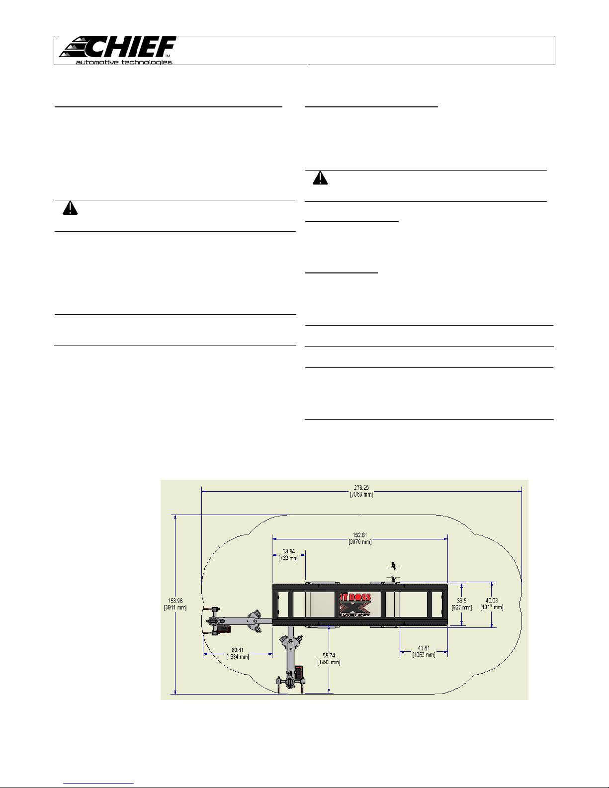
Machine Placement
The PIT BOSS System has many accessories that add to the overall footprint of the lift. Use Figure 26 as a guide to
plan for the working space needed when installing the PIT BOSS.
Refill Hydraulic Fluid Reservoir
The hydraulic pump contains 1.75 quarts (1.7 liters) of
hydraulic oil. When refilling or adding oil, fill to within 1” (25
mm) of fill port using SUS 215 viscosity @1008F (388C) 10W
hydraulic oil.
CAUTION:
Scissor Lift Assembly
All scissor lift pivot points are permanently lubricated and do
not require maintenance except for occasional cleaning.
Scissor Lift Base
Using compressed air, blow dirt and debris from the base. If
necessary, use stiff brush to remove build up of dust and paint
on the surface.
CAUTION:
NOTE:
Fill pump reservoir with all cylinders
retracted and lift in lowest position.
DO NOT overfill pump reservoir.
Wear safety glasses while using
compressed air to blow out dirt and dust.
Refer to Parts Manual for detailed
exploded views of referenced parts.
Contact Chief Automotive with any
questions regarding the usage or
maintenance of the PIT BOSS system.
Figure 26
13
Page 16
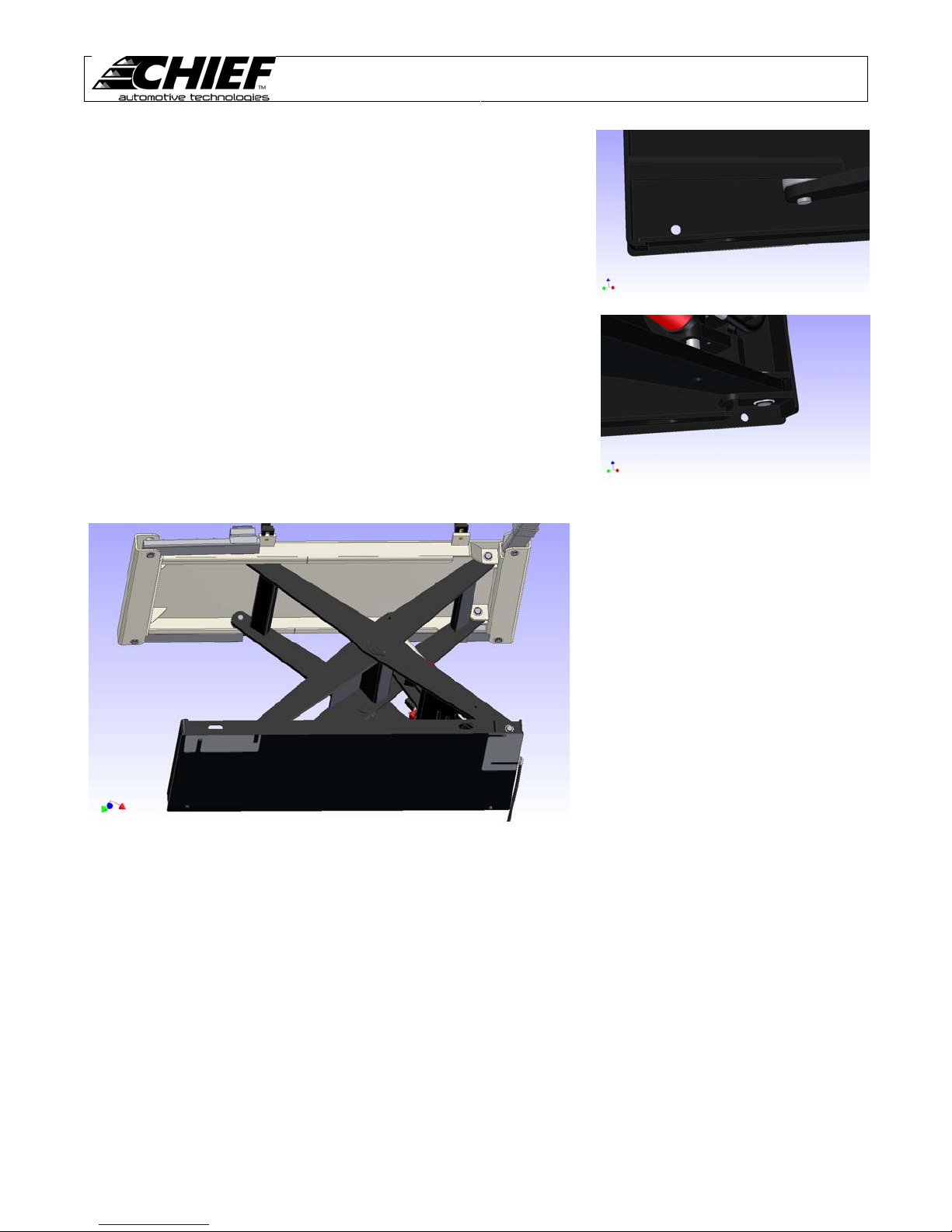
Machine Leveling
1. Position the PIT BOSS lift in the highest working position.
2. Use the scissor base as a template and a drill guide to install four (4)
concrete anchors (see Figure 27 & 28). See Anchoring section for more
information
3. Move around the machine placing a l evel across the front, rear, and down
both sides of the top. The machine should be level in all working heights.
4. Adjust level by adding the shims (see F igure 29). Repeat this process until
the machine is level on all corners.
5. Once the machine is level tighten the nuts on the concrete anchors. DO
NOT use an impact wrench for tightening
6. Depending on how many shims where placed under the PIT BOSS, shims
may need to be added to the Shop-Hopper. Shims for the Shop-Hopper are
placed between the caster and the frame.
PIT BOSS
Users Manual
Figure 27
Figure 28
Figure 29
14
Page 17
PIT BOSS
Users Manual
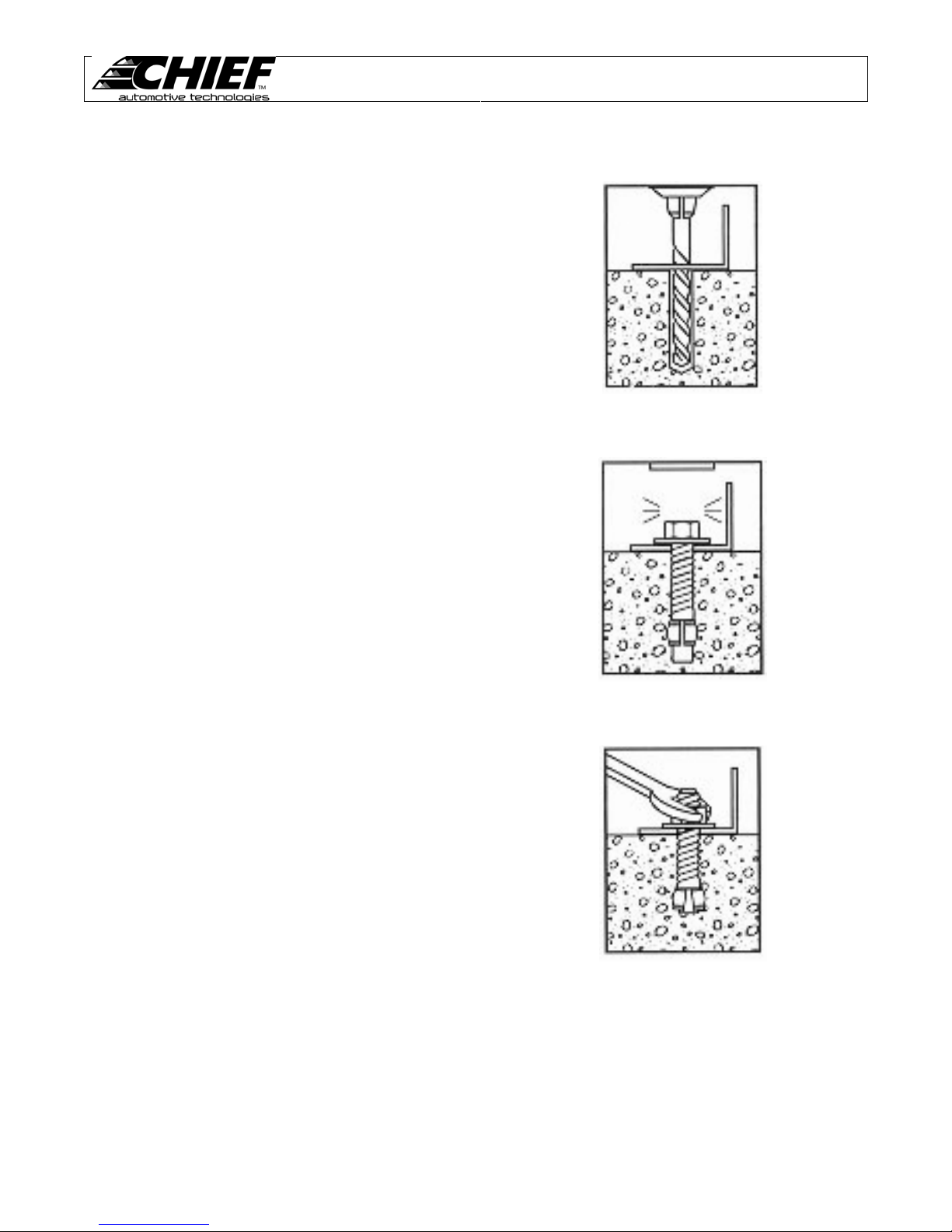
Machine Anchoring
1. Anchors must be installed at least 5-11/16” from
any edge or seam in concrete.
2. The concrete must be at least 4-1/4” thick with a
compressive strength of 3000psi.
3. Use a hammer drill with a carbide tip, ¾” diameter
solid drill bit. The bit tip diameter should be to ANSI
Standard B95.12-1977 (.775” to .787”).
4. Keep drill perpendicular to the floor while drilling.
Let drill do the work. Drill the hole completely
through the slab. Clean dust from hole using a
vacuum. (See Figure 30)
5. Assemble the washers and nuts onto the anchor
bolts. Thread the nuts onto the anchor bolts where
the top of the nuts are just above the top of the
bolts, as shown.
6. Using a hammer, carefully tap the anchor bolts into
the concrete until the washer rests against the base
plate.(See Figure 31)
7. If more than 2” of shimming is required, do not use
the anchors and shims provided with the lift. Use
longer anchors and fabricate larger shims from
steel flat.
8. Once the machine is level, tighten the anchor bolts
to 150 ft-lbs. Do not use an impact wrench on
anchor bolts. (See Figure 32)
Figure 30
Figure 31
Figure 32
15
Page 18
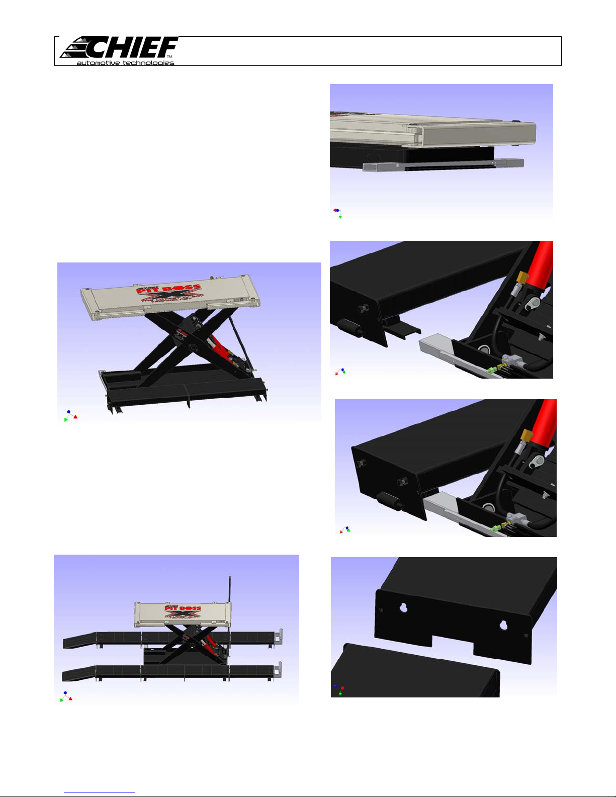
Machine Ramps and Tread ways
The ramps and tread ways are used when the PIT BOSS has not
been placed within a pit. The tread ways give 6 inches of
elevation enabling the vehicle to be driven over the PIT BOSS.
1. Install the tread way locating brackets. The brackets bolt
on the ends of the lift base and are each secured with
two 3/8 bolts (see Figure 33).
2. Each tread way has a piece of channel iron on the
bottom. Select four tread ways without wheel stops and
insert the channel iron of the tread ways completely into
the locating brackets (see Figure 34 and Figure 35). B e
certain the ends of the tread ways with out bolts are away
from each other (see Figure 36).
PIT BOSS
Users Manual
Figure 33
Figure 36
3. Now repeat step 2 for the ot her side of the PIT BOSS.
Next locate the two tread ways with wheel stops and
place them at the lift cylinder end. Opposite the wheel
stops are keyholes in the tread ways. Li ne the keyholes
up with the exposed bolts on the mating tre ad way and
insert them (see Figure 37).
4. Lock the remaining two tread ways on the opposite end
as the wheel stops. Place the ramps with the slots over
the bolts (see Figure 38).
Figure 34
Figure 35
Figure 38
16
Figure 37
Page 19
PIT BOSS
Users Manual
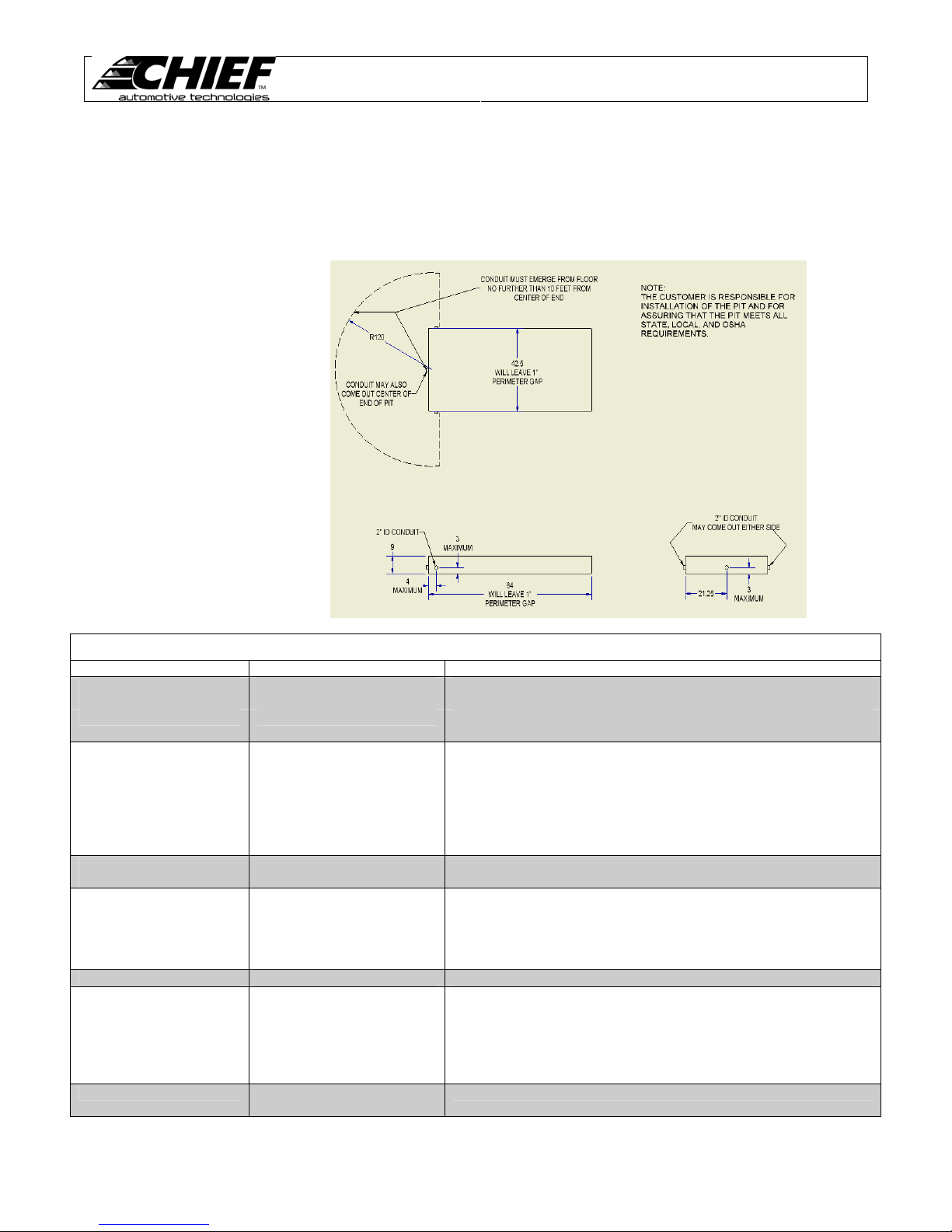
Machine Pit Layout
The PIT BOSS is designed specifically for use in a flush mount pit. Figure 39 shows the pit dimensions. For maximum
effectiveness it is essential that the hydraulic and air lines be run in cond uit under the surface of the floor. The c onduit should
be 2” inside diameter and must be acceptable for the use with concrete. Where ever the conduit emerges will mark the
location of the pump and stand. Be certain this is an acceptable area clear of traffic. The profile of the PIT BOSS and
accessories is shown in Figure 26. Placement of the pit should tak e into account these accessories plus additional space
needed for a comfortable work area.
Figure 39
Troubleshooting
PROBLEM CAUSE
Pump will not Run Air supply disconnected Plug in air supply
Air supply not energized Turn on air supply
Bad pump Replace pump. Contact Chief Automotive Service Representative
Pump will not build
pressure or builds
pressure slowly
Contamination in fluid Remove and clean fluid. Contact Chief Automotive Service
Contamination in cylinders Remove and inspect cylinders. (Refer to parts manual). Contact
Pump will not hold
pressure
Pump stalls or will not
start under pressure
Too much weight
Tower cylinder jumps Air in hydraulic system Bleed hydraulic system
Tower cylinder will not
extend
Auxiliary line not connected
Lift switch turned on Turn off lift switch
Pump will not build pressure See pump problems above
Collars jump under load Improper fit between collar
Hydraulic fluid low Fill fluid reservoir to within 1” (25 mm) of top with SUS215 viscosity
Hydraulic oil leak Check hoses, fittings, cylinders, and quick couplers for leaks.
Contamination in fluid Remove and clean elbow fittings at cylinders. Contact Chief
Insufficient air supply
Auxiliary line valve closed Open auxiliary line valve one turn
to tower
and tower pipe
POSSIBLE SOLUTION
for replacement.
@ 100°F (38C) 10W hydraulic oil with all cylinders down and
machine in loading position.
Representative.
Chief Automotive service representative.
Tighten or replace if necessary
Automotive Technologies Service Representative.
Maximum total lift capacity (including 2000 lb Shop Ho pp er) is 85 0 0
lbs.
Use different air supply.
Connect auxiliary line to tower
Refit collar – Contact Chief Automotive service representative.
17
Page 20

P.O. Box 1368
Grand Island, Nebraska 68802-1368
Phone: 308/384-9747
Fax: 308/384-8966
www.chiefautomotive.com
Chief reserves the right to alter product specifications
and/or packaging components without notice
Form 1-PIT BOSSUM (rev 01/08)
Part No. 638699
 Loading...