

Page 1
INSTALLATION INSTRUCTIONS
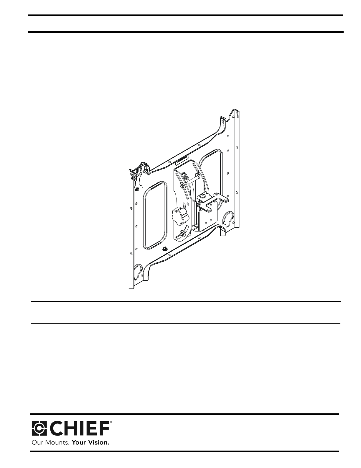
Swivel Accessory for Carts and Stands
PAC790
Page 2
PAC790 Installation Instructions
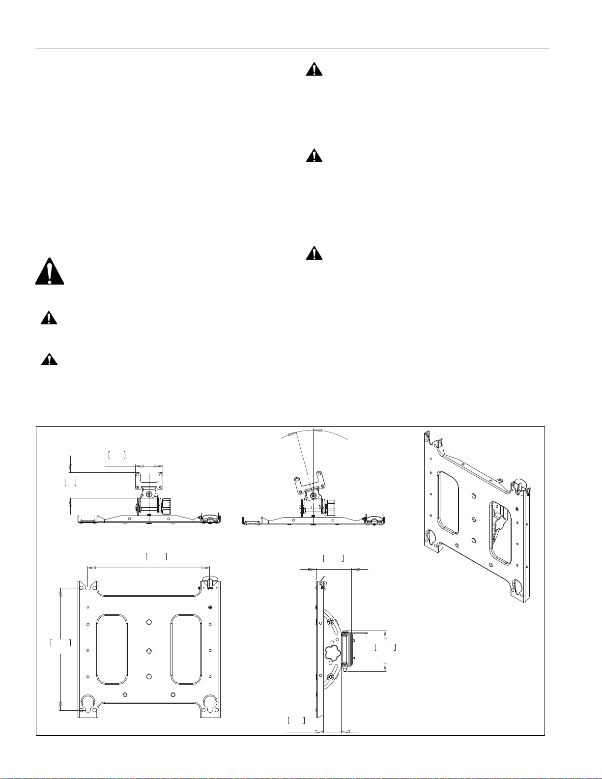
14.00
355.6
14.00
355.6
3.20
81.3
2.95
75
4.01
101.8
4.67
118.5
2.03
51.6
15° MAX SWIVEL ANGLE
DISCLAIMER
Milestone AV Technologies, and its affiliated corporations and
subsidiaries (collectively, "Milestone"), intend to make this
manual accurate and complete. However, Milestone makes no
claim that the information contained herein covers all details,
conditions or variations, nor does it provide for every possible
contingency in connection with the installation or use of this
product. The information contained in this document is subject
to change without notice or obligation of any kind. Milestone
makes no representation of warranty, expressed or implied,
regarding the information contained herein. Milestone assumes
no responsibility for accuracy, completeness or sufficiency of
the information contained in this document.
Chief® and ClickConnect™ are registered trademarks of
Milestone AV Technologies. All rights reserved.
WARNING:
follow all instructions can result in serious personal injury,
damage to equipment, or voiding of factory warranty! It is the
installer’s responsibility to make sure all components are
properly assembled and installed using the instructions
provided.
WARNING:
for this component can result in serious personal injury or
damage to equipment! It is the installer’s responsibility to
make sure the structure to which this component is attached
can support five times the combined weight of all equipment.
Reinforce the structure as required before installing the
component.
Failure to read, thoroughly understand, and
Failure to provide adequate structural strength
CAUTIONS!
WARNING:
serious injury or death if you do not follow the instructions.
CAUTION:
damage or destruction of equipment if you do not follow the
corresponding instructions.
DIMENSIONS
IMPORTANT WARNINGS AND
A WARNING alerts you to the possibility of
A CAUTION alerts you to the possibility of
WARNING:
serious personal injury or damage to equipment! It is the
installer’s responsibility to make sure the combined weight of
all components mounted on the accessory does not exceed
200 lbs (90.72 kg) or the specific weight limit of the cart or
stand that it is mounted to.
Exceeding the weight capacity can result in
2
Page 3
Installation Instructions PAC790
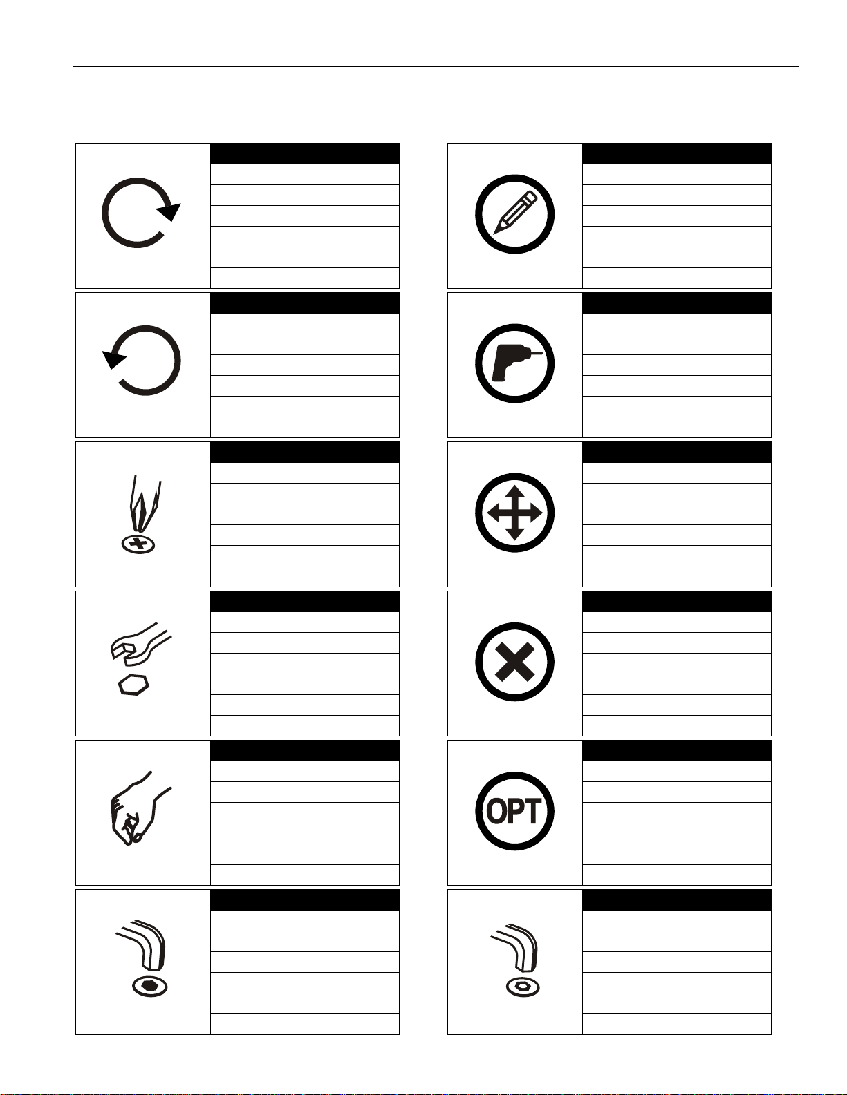
Tighten Fastener
Apretar elemento de fijación
Befestigungsteil festziehen
Apertar fixador
Serrare il fissaggio
Bevestiging vastdraaien
Serrez les fixations
Loosen Fastener
Aflojar elemento de fijación
Befestigungsteil lösen
Desapertar fixador
Allentare il fissaggio
Bevestiging losdraaien
Desserrez les fixations
Phillips Screwdriver
Destornillador Phillips
Kreuzschlitzschraubendreher
Chave de fendas Phillips
Cacciavite a stella
Kruiskopschroevendraaier
Tournevis à pointe cruciforme
Open-Ended Wrench
Llave de boca
Gabelschlüssel
Chave de bocas
Chiave a punte aperte
Steeksleutel
Clé à fourche
By Hand
A mano
Von Hand
Com a mão
A mano
Met de hand
À la main
Hex-Head Wrench
Llave de cabeza hexagonal
Sechskantschlüssel
Chave de cabeça sextavada
Chiave esagonale
Zeskantsleutel
Clé à tête hexagonale
Pencil Mark
Marcar con lápiz
Stiftmarkierung
Marcar com lápis
Segno a matita
Potloodmerkteken
Marquage au crayon
Drill Hole
Perforar
Bohrloch
Fazer furo
Praticare un foro
Gat boren
Percez un trou
Adjust
Ajustar
Einstellen
Ajustar
Regolare
Afstellen
Ajuster
Remove
Quitar
Entfernen
Remover
Rimuovere
Verwijderen
Retirez
Optional
Opcional
Optional
Opcional
Opzionale
Optie
En option
Security Wrench
Llave de seguridad
Sicherheitsschlüssel
Chave de segurança
Chiave di sicurezza
Veiligheidssleutel
Clé de sécurité
LEGEND
3
Page 4
Installation Instructions PAC790
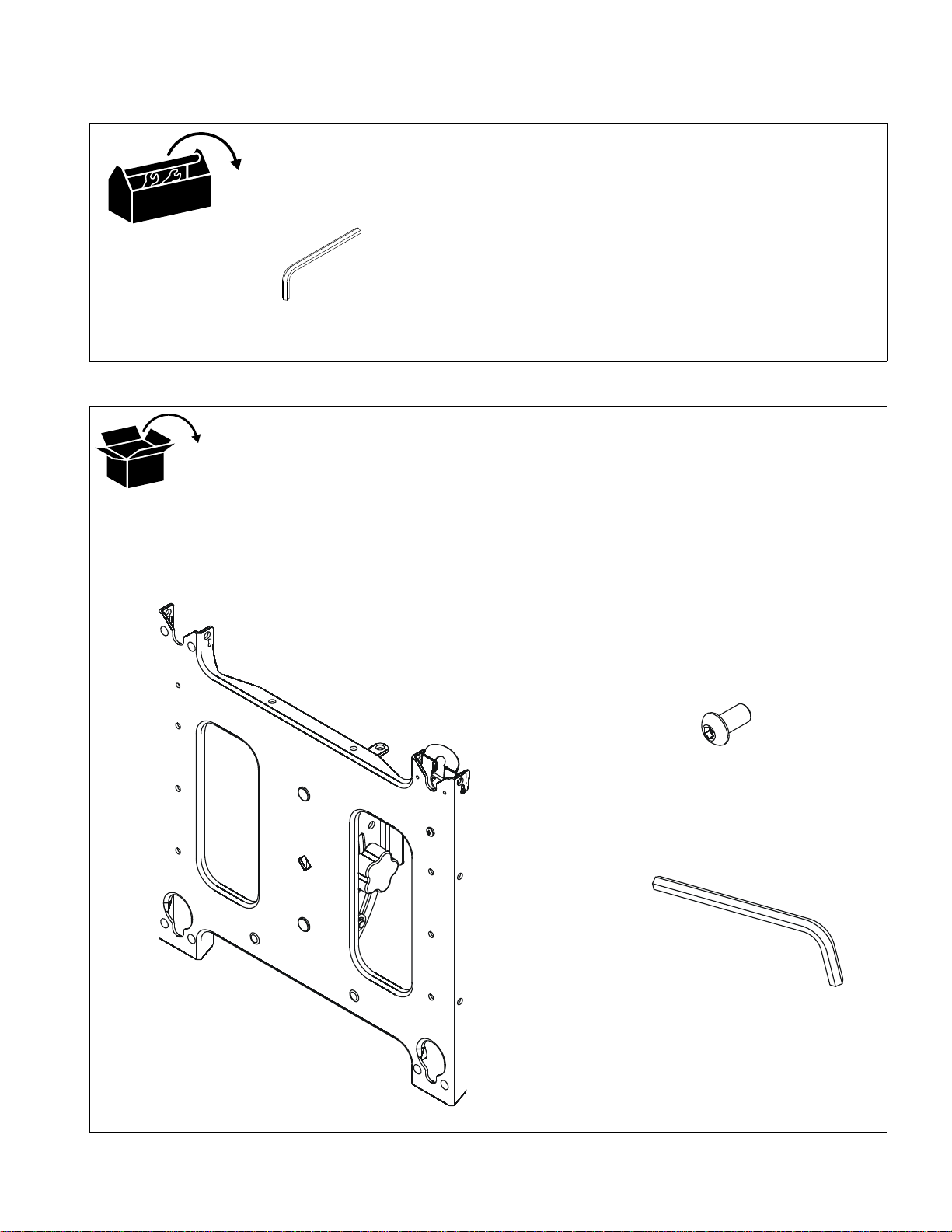
3/16"
(included)
A (1
[swivel accessory]
B(4)
5/16-18 x 5/8"
C(1)
3/16"
TOOLS REQUIRED FOR INSTALLATION
PARTS
4
Page 5
Installation Instructions PAC790
(A)
1
(B) x 4
(Back view of cart/stand)
ClickConnect
lock at TOP of
head assembly
cart/stand
assembly
2
5
ASSEMBLY
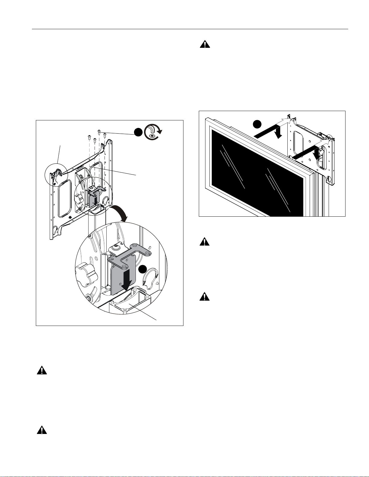
Attaching Head to Cart/Stand Assembly
IMPORTANT ! : When attaching head assembly ensure
that the ClickConnect lock is at TOP of head assembly.
(See Figure 1)
1. Slide swivel accessory (A) into the cart/stand assembly.
(See Figure 1)
2. Attach swivel accessory to cart/stand using four 5/16-18 x
3/8" button head cap screws (B). (See Figure 1)
CAUTION:
adjusting the height of the cart/stand.
1. Attach PSBU or MSBU interface bracket(s) to the display(s)
following the instructions included with the bracket.
2. While supporting both sides of display, align four mounting
buttons on display or interface bracket with four mo unting
holes in head assembly. (See Figure 2)
AL WAYS remove the display(s) BEFORE
Attaching Display to Accessory
Figure 1
WARNING:
MAY LEAD TO SERIOUS PERSONAL INJURY OR
DAMAGE TO EQUIPMENT! It is the installer’s responsibility
to make sure the combined weight of all components
mounted on the accessory does not exceed 200 lbs (90.72
kg) or the specific weight limit of the cart or stand that it is
mounted to.
EXCEEDING MAXIMUM WEIGHT CAPACITY
Figure 2
WARNING:
LBS! Always use two people and proper lifting techniques
when installing or positioning display on stand.
3. Lower display into place listening for audible "click" to
ensure recessed area of mounting buttons are properly
seated in lower area of mounting holes.
WARNING:
STAND OR DISPLAY FALLING CAUSING SERIOUS
PERSONAL INJURY OR DAMAGE TO EQUIPMENT!
Ensure mounting buttons are completely engaged in
mounting holes.
NOTE:
DISPLAY MAY WEIGH IN EXCESS OF 40
IMPROPER INSTALLATION CAN LEAD TO
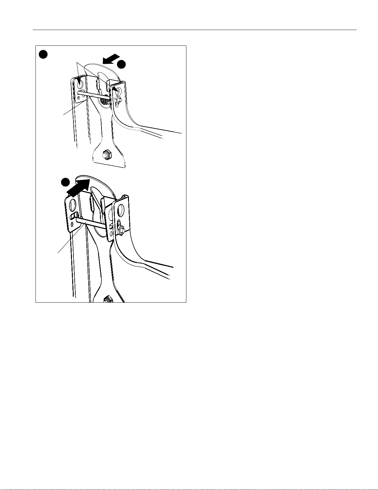
Holes are provided in the faceplate for use with a
padlock or similar locking device, if desired. In addition,
the pin and nut may be removed from the upper holes
and moved to the lower holes for use as a more
permanent locking device. (See Figure 3)
WARNING:
ensure the cart/stand is on level surface.
Before attaching display(s) to the cart/stand
5
Page 6
PAC790 Installation Instructions
5
4
Remove pin
and nut and
move to lower holes
A padlock or bolt may
be placed through latch
holes
1
3
4
Place optional bolt
(not provided) here
to lock in an upright
position.
2
Place optional bolt
(not provided) here
to lock in straight position.
1
1
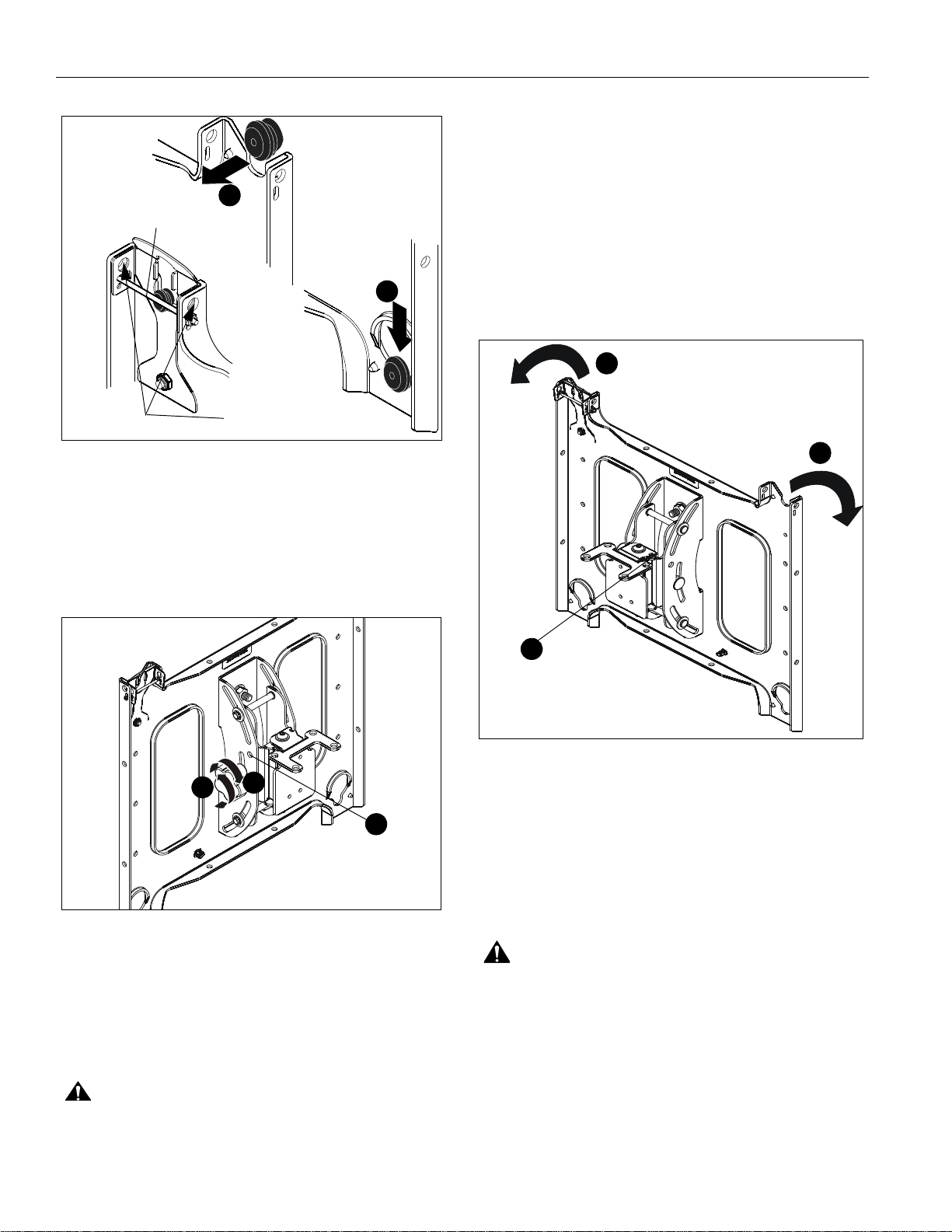
recommended that a bolt (not provided) be placed through
the head assembly (See Figure 4) to lock the display into
the upright position.
Swivelling Display
The display can be swivelled up to 15° either left or right from a
straight upright position.
1. Swivel display to the left or right up to 15° until desired
position is reached. (See Figure 5)
2. If leaving display in straight position, it is recommended that
a bolt (not provided) be placed through the hole on the
swivel device to lock the display into that position. (See
Figure 5)
Figure 3
Tilting Display
The display can be tilted up to 15° either backward or forward
from a straight upright position.
1. Turn knob counterclockwise on back of head assembly to
loosen the tilt. (See Figure 4)
Figure 4
2. Tilt display as desired, to a maximum of 15° either forward
or backward.
3. Turn knob clockwise to tighten display on head assembly.
(See Figure 4)
CAUTION:
prevent damage to the stand.
4. If leaving the display in a straight upright position, it is
6
Tighten knob on back of head assembly to
Figure 5
Removing Display
1. Remove bolt or padlock from faceplate (if used).
NOTE:
2. Pull back on flag on upper mounting hole and press pin
3. Carefully lift display from cart/stand.
4. Lift up on pin and place flag back against faceplate to return
The pin may have been used as a more permanent
locking device. If so, remove nut and pin and move
from the lower holes to the upper holes.
down into "Open" position.(See Figure 6)
WARNING:
LBS! Always use two people and proper lifting techniques
when installing or positioning display on cart/stand.
it to "Closed" position. (See Figure 6)
DISPLAY MAY WEIGH IN EXCESS OF 40
Page 7
Installation Instructions PAC790
2
1
Remove bolt
or padlock
if used
Pin in
"Open"
position -
Pin in
"Closed"
position -
4
move to
"Open"
position to
move to
"Closed"
position
remove
display
after display
is removed.
Figure 6
7
Page 8

PAC790 Installation Instructions
Chief Manufacturing, a products division
of Milestone AV Technologies
8807-002001 Rev 00
©2009 Milestone AV Technologies, a
Duchossois Group Company
www.chiefmfg.com
05/09
USA/International A 8401 Eagle Creek Parkway, Savage, MN 55378
P 800.582.6480 / 952.894.6280
F 877.894.6918 / 952.894.6918
Europe A Fellenoord 130 5611 ZB EINDHOVEN, The Netherlands
P +31 (0)40 2668620
F +31 (0)40 2668615
Asia Pacific A Room 24F, Block D, Lily YinDu International Building
LuoGang, BuJi Town, Shenzhen, CHINA.
P +86-755-8996 92 26
F +86-755-8996 9217
 Loading...