

Page 1
I N S T R U C T I O N M A N U A L
peaker Mount Assembly
PAC-300)
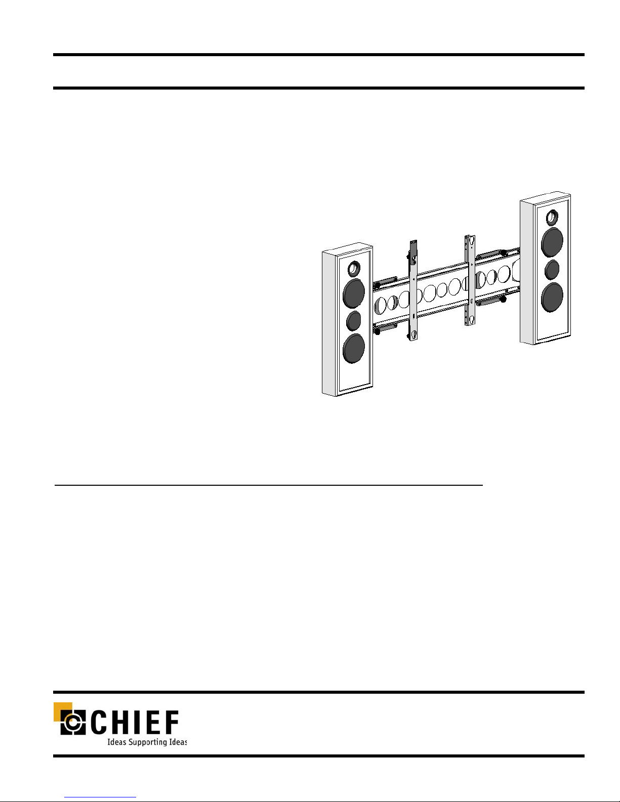
The Speaker Mount Assembly (PAC-300) is designed to
fit up to most 50” screens. The mount attaches to the
center of the speaker, adding only about one inch to the
depth of the mount and 20 pounds to the weight.
Height adjust ability of the mount is two inches, one inch
up and one inch down, from the center in one-half inch
increments.
BEFORE YOU BEGIN
• CAUTION: T o prevent da mage to the PAC-300, which could affect or void the Factory warranty , t horoughly
study all instructions and illustrations before you begin to install or operate the unit. Pay particular attention to the “Important Precautions” on Page 1.
• The maximum weight to be installed on the PAC-300 is limited by the weight specification of mount.
• If you have any questions about this assembly, contact Chief Manufacturing at 1-800-582-6480.
CHIEF MANUFACTURING INC.
1-800-582-6480 952-894-6280 FAX 952-894-6918
8401 EAGLE CREEK PARKWAY STE. 700
SAVAGE, MINNESOTA 55378 USA
PART NO. 8800-000029 (Rev. B)
©2004 Chief Manufacturing
www.chiefmfg.com
Printed in USA 05-04
Page 2

Instruction Manual PAC-300
1
IMPORTANT WARNINGS and CAUTIONS!
WARNING: A WARNING alerts you to the possibility of serious injury or death if you do not follow the instructions.
CAUTION: A CAUTION alerts you to the possibility of damage or destruction of equipment if you do not follow the corre-
sponding instructions.
• WARNING: The maximum weight to be installed on the PAC-300 is limited to the weight specification of your mount.
• CAUTION: Inspect the unit for shipping damage.
• CAUTION: Drilling holes in a speaker may damage speaker.
TOOLS REQUIRED FOR INSTALLATION
• Phillips screwdriver
• 3/8” and 7/16” wrench
• Socket set with extension
• Allen wrench set
NOTE: Other tools may be required depending on the
method of installation.
CONTENTS
INSPECT PARTS BEFORE ASSEMBLY ..... 2
Inspect The Mount ...................................... 2
ASSEMBLE MOUNT .................................... 3
MOUNT DISPLAY......................................... 5
MOUNT SPEAKERS..................................... 6
Speaker Bracket Attachment....................... 6
Speaker Mounting....................................... 7
Page 3
2
Instruction Manual PAC-300
INSPECT PARTS BEFORE ASSEMBLY
Inspect The Mount
1. Carefully inspect the mount for shipping damage. If any
damage is apparent, call your carrier claims agent and do
not continue with the assembly procedure until the carrier
has reviewed the damage.
NOTE:
Read all assembly instructions before start-
ing assembly.
2. Carefully inspect the Speaker Mount
Assembly (PAC-300) components for
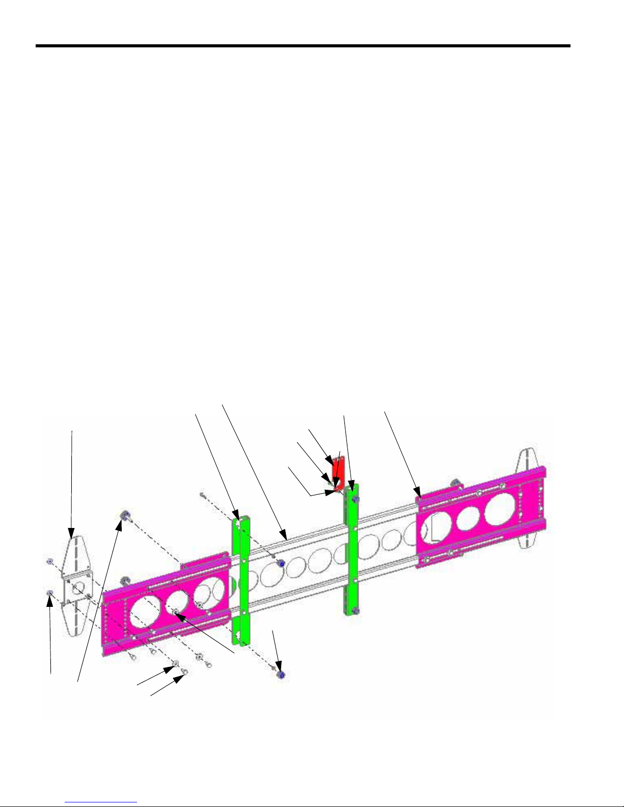
damage (See Figure 1).
Figure 1. Speaker Mount Assembly
10. Speaker Mount Cross Support
20. Speaker Mount Button Support (Left)
30. Speaker Mount Button Support (Right)
40. Speaker Mount End Support (Qty. 2)
50. Speaker Bracket (Qty. 2)
60. Latching Flag
70. 10-24X1/2” Phillips Undercut Screw
80. Nylon Spacer
Item #
10
20
30
40
50
60
70
80
90
100
110
120
130
140
150
90. 10-24 Nylock Nut (Qty. 5)
100. Mounting Button (Qty. 4)
110. 10-24X7/8” Button Head Cap Screw (Qty. 4)
120. Rubber Washer (Qty. 8)
130. Thumb Screw Knob (Qty. 4)
140. Flat Washer (Qty. 8)
150. 1/4-20X1/2” Hex Head Cap Screw (Qty. 20)
Item #
Page 4
Instruction Manual PAC-300
3
ASSEMBLE MOUNT
NOTE: Numbers in ( ) refer to parts shown
in Figure 1.
Assemble mount as follows:
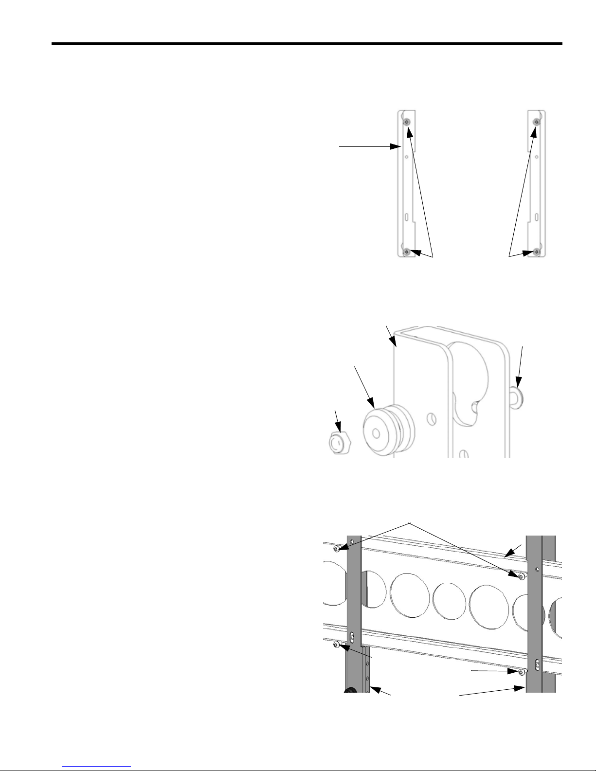
1. Attach two mounting buttons (100) to left speaker mount
button support (20) and right speaker mount button support (30) using four 10-24X7/8” button head cap
screws (110) and four Nylock nuts (90) (see Figure 1,
Figure 2 and Figure 3).
2. Install left speaker mount button support (20) and right
speaker mount button support (30) on speaker mount
cross support (10) and secure using four 1/4-20X1/2” hex
head cap screws (150) (see Figure 4). NOTE: Installing
screws on top first makes installing screws in slotted
holes on bottom last is easier.
Figure 2. Mounting Button Location
Figure 4. Button Supports to Cross Support
Mounting Buttons
Button Support
Figure 3. Mounting Button Attachment
Mounting Button
Button Support
10-24X7/8”
Button Head
Cap Screw
10-24
Nylock
Nut
Cross Support
Button Support
Install Top1/4-20X1/2” Hex Head Cap Screws First
Cap Screws Last
Install Bottom
1/4-20X1/2” Hex Head
Page 5
4
Instruction Manual PAC-300
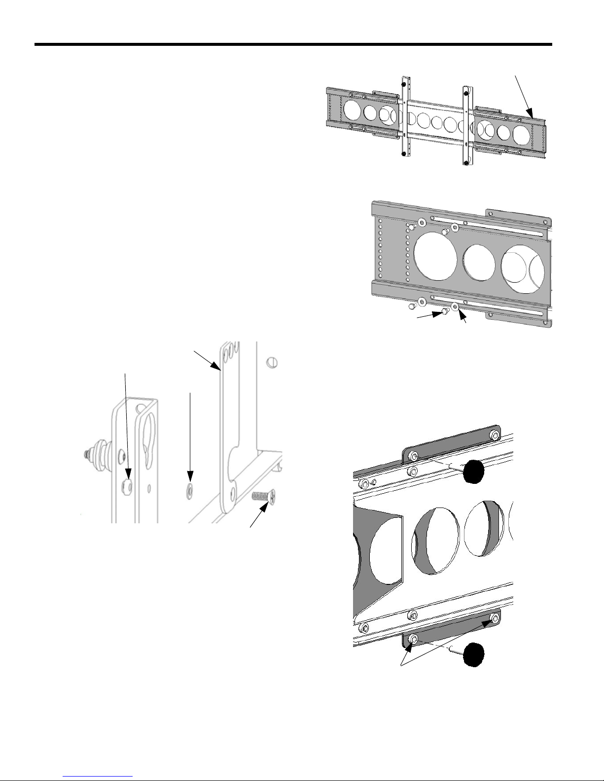
3. Install the speaker mount end supports (40) on the
speaker mount cross support (10) and secure each
speaker mount end support using four flat washers (140)
and four 1/4-20X1/2” hex head cap screws (150) (see
Figure 5 and Figure 6).
4. Install the latching flag (60) using the 10-24X1/2” Phillips
undercut screw (70), Nylon spacer (80) and 10-24 Nylo ck
nut (90) (see Figure 7).
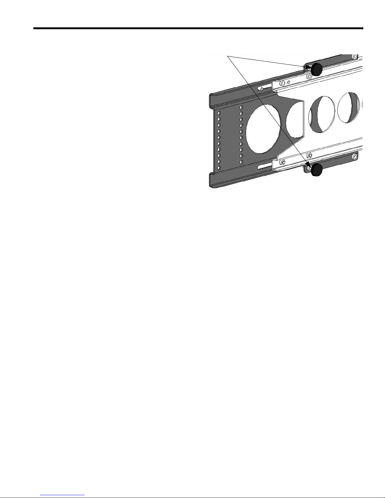
5. Install the thumb screw knobs (130) (see Figure 8).
Figure 7. Install Latching Flag
10-24 Nylock Nut
Nylon Spacer
Latching Flag
10-24X1/2” Phillips Undercut Screw
Figure 8. Install Thumb Screw Knobs
Attach thumb screw knobs in
one of these two holes (both sides)
depending upon screen size
Figure 6. Speaker Mount End Support Attachment
1/4-20X1/2” Hex Head
Cap Screw
Flat Washer
Figure 5. Speaker Mount End Supports
Speaker Mount End Support
Page 6
Instruction Manual PAC-300
5
MOUNT DISPLAY
1. Install PSB brackets on the display according to the
instructions accompanying the brackets for your display.
2. Install the display on the mount according to instructions
accompanying the PSB brackets for your display.
3. Adjust the thumb screw knobs (130) against the display
to stabilize the display if necessary (see Figure 9).
Figure 9. Adjust Thumb Screw Knobs
Adjust thumb screw knobs against back of display
Page 7
6
Instruction Manual PAC-300
SPEAKER ATTACHMENT
Speaker Bracket Attachment
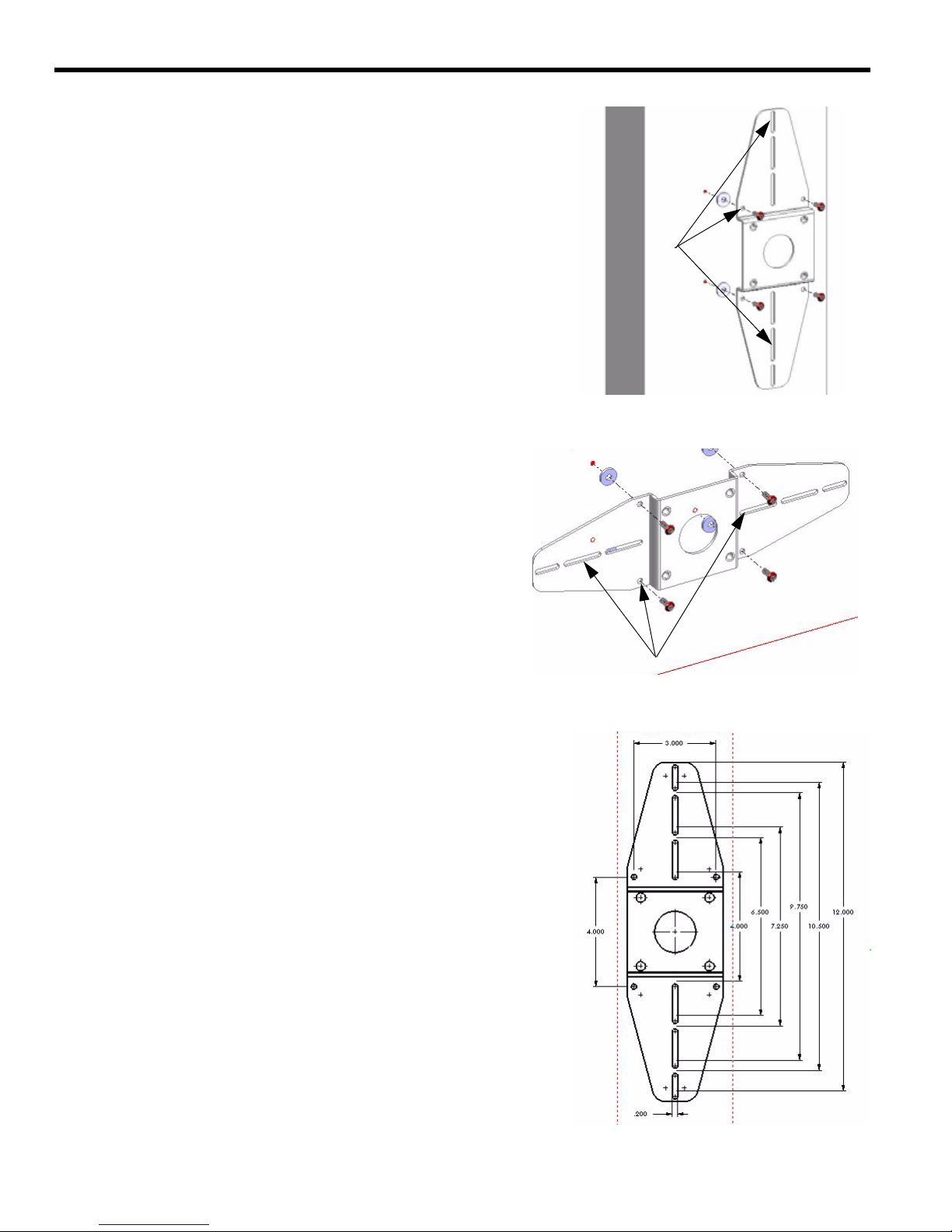
1. If speakers have inserts for brackets, install two speaker
brackets (50) on speaker (see Figure 10 and Figure 11).
Brackets may be vertically or horizontally using the 3”X4”
pattern and/or slotted holes.
CAUTION: Drilling holes in a speaker may damage speaker.
2. If speakers do not have inserts for brackets, confirm with
your speaker manufacturer that you can drill holes for
attaching mounting brackets.
3. After confirming with your speaker manufacturer that yo u
can drill holes for attaching mounting brackets, drill holes
and attach mounting bracket (see Figure 10, Figure 11
and Figure 12).Brackets may be vertically or horizontally
using the 3”X4” pattern and/or slotted holes.
Figure 12. Bracket Dimensions
Figure 11. Horizontal Bracket Mounting Option
A
ttachment Options
Figure 10. Vertical Bracket Mounting Option
Attachment Options
Page 8
Instruction Manual PAC-300
7
Speaker Mounting
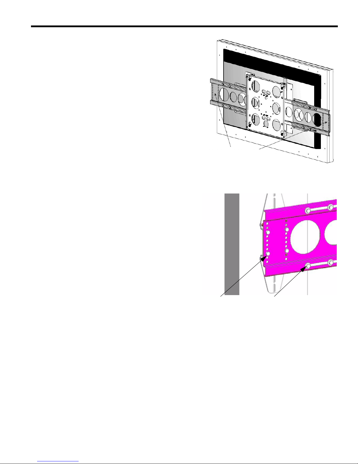
1. Loosen (Do not remove) four 1/4-20X1/2” hex head cap
screws (150) securing speaker mount end support (40)
on each side of mount (see Figure 13)
2. Extend speaker mount end supports (40) to facilitate
speaker attachment.
3. Place each speaker, with mounting bracket attached, at
desired height on mount, align mounting holes, and
secure using four 1/4-20X1/2” hex head cap
screws (150).
4. Slide speaker mount end supports (40) to accommodate
the desired position and secure in place by tightening
1/4-20X1/2” hex head cap screws (150).
Figure 14. Speaker Mounting and Adjustment
Mounting Bolts
Adjustment Bolts
Adjust speaker mount end supports
Figure 13. Speaker End Support Adjustment
 Loading...