

Page 1
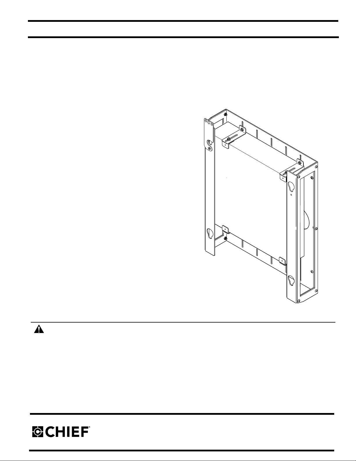
INSTALLATION INSTRUCTIONS
CPU/DVD and VCR Mounting Accessory
Model: PAC-251
The PAC-251 allows the integration of a CPU, DVD Player or
VCR into installations using most Chief Large Flat Panel Display
mounts. This accessory easily adapts to Chief's patented
Q-Latch™ Mounting system and also allows for easy access to
drives and input/output connections.
Fits Equipment Dimensions:
5.125"–17.625" W x 1.5"–3.5" H x 3.5"–15.5" D
BEFORE YOU BEGIN
WARNING:
SERIOUS PERSONAL INJURY, DAMAGE TO EQUIPMENT, OR VOIDING OF FACTORY WARRANTY! It is the installer’s
responsibility to make sure all components are properly assembled and installed using the instructions provided.
• If you have any questions about these instructions or your specific installation, contact Chief Manufacturing at
1-800-582-6480 or 952-894-6280.
Chief® is a trademark of Milestone AV Technologies, Inc. All rights reserved.
FAILURE TO READ, THOROUGHLY UNDERSTAND, AND FOLLOW ALL INSTRUCTIONS CAN LEAD TO
8809-000011 Rev D
©2008 Chief Manufacturing, a division of Milestone AV Technologies
8401 Eagle Creek Parkway, Savage, MN 55378
P: 800.582.6480 / 952.894.6280 F: 877.894.6918 / 952.894.6918
©2008 Milestone AV Technologies
www.chiefmfg.com
10/08
Page 2

Model: PAC-251 Installation Instructions
IMPORTANT WARNINGS AND CAUTIONS!
WARNING: A WARNING alerts you to the possibility of serious injury or death if you do not follow the instructions.
CAUTION: A CAUTION alerts you to the possibility of damage or destruction of equipment if you do not follow the corresponding
instructions.
WARNING:
SERIOUS PERSONAL INJURY OR DAMAGE TO EQUIPMENT! It is the installer’s responsibility to make sure the structure to
which this accessory is attached can support five times the combined weight of all equipment.
WARNING:
EQUIPMENT! It is the installer’s responsibility to make sure the combined weight of the PAC-251, device, and any other attached
equipment does not exceed the capacity of PST display mount as stated in the installation instructions provided with the PST
mount. .
FAILURE TO PROVIDE ADEQUATE STRUCTURAL STR ENGTH FOR THIS ACCESSORY CAN RESULT IN
EXCEEDING MAXIMUM WEIGHT CAP ACITY CAN RESULT IN SERIOUS PERSONAL INJURY OR DAMAGE TO
2
Page 3
Installation Instructions Model: PAC-251
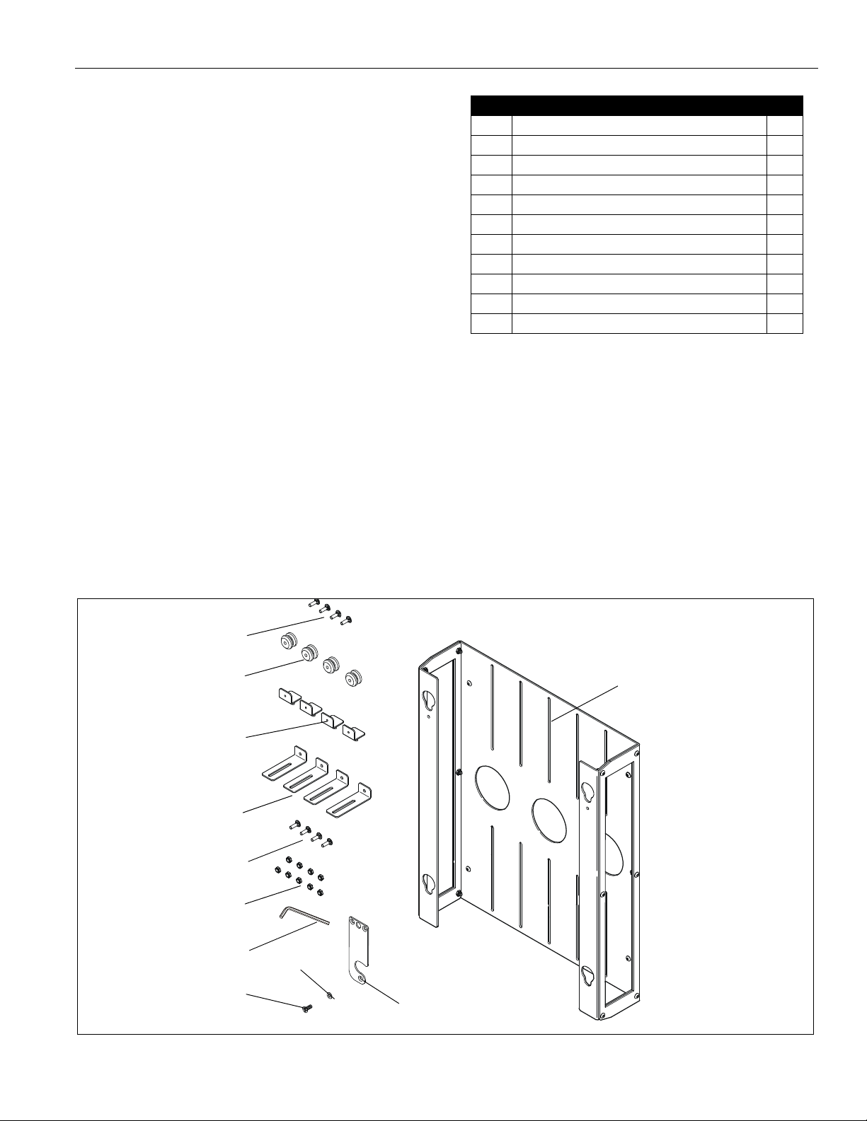
Item Description Qty
10 RACK, device Mounting 1
20 BRACKET, device Holding 4
30 BRACKET, device Mounting 4
40 BUTTON, Mounting 4
50 SCREW, Flat Head Cap, 10-24 x 1/2" (Black) 4
60 SCREW, Round Head Carriage Bolt, 10-24 x 5/8" 4
70 NUT, Nylock, 10-24 9
80 WRENCH, Hex, 1/8" (Provided) 1
90 FLAG, Latching 1
100 SCREW, Phillips Machine, 10-24 x 1/2" 1
110 WASHER, Flat 1
10
20
30
40
50
60
70
80
100
110
90
TOOLS REQUIRED FOR INSTALLATION
• 1/8" Hex Wrench (provided)
PARTS
Unpack carton, inspect and verify contents. Read installation
instructions completely. If any listed parts are missing,
immediately contact a Chief Customer Service representative
by calling 1-800-582-6480, or by visiting www.chiefmfg.com.
Figure 1: PARTS
3
Page 4
Model: PAC-251 Installation Instructions
1
2
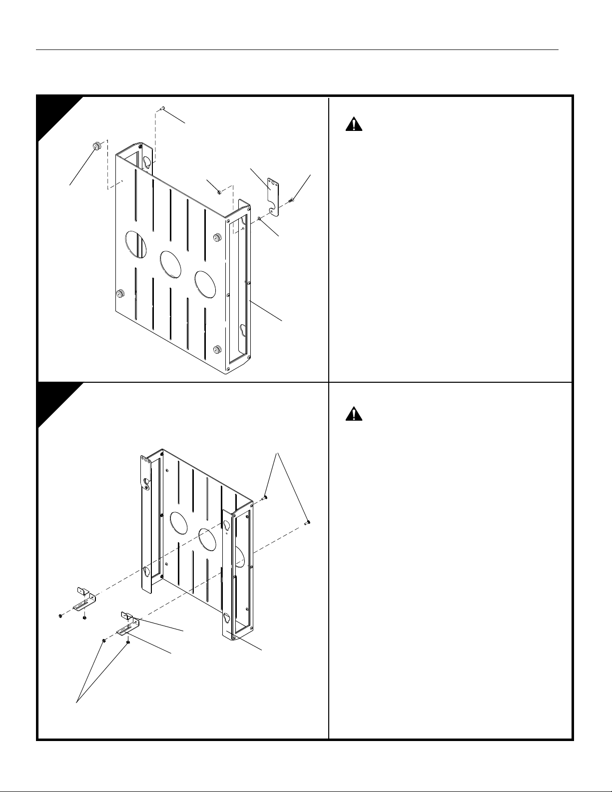
Install Lower device Mounting Brackets
WARNING:
IMPROPER INST ALLATION CAN
LEAD TO DEVICE FALLING! All mounting brackets
must be securely fastened to device rack.
1. Install two lower device mounting brackets (30) to
device rack (10) using two 10-24 x 5/8" round head
carriage bolts (60) and two 10-24 Nylock nuts (70).
NOTE:
Make certain the device mounting brackets (30)
are oriented as show in the figure at left. DO
NOT tighten hardware at this time!
2. Secure two lower device holding brackets (20) to
device mounting brackets (30) using two 10-24
Nylock nuts (70).
NOTE:
DO NOT tighten hardware at this time!
3. Measure height of device and position brackets (20
and 30) so that device will be centered vertically in
device rack (10).
4. Secure two lower device mounting brackets (30) to
device rack (10) by tightening two 10-24 x 5/8"
round head carriage bolt (60) and two 10-24 Nylock
nuts (70).
Install Mounting Buttons and Latching Fl ag
WARNING:
IMPROPER INST ALLATION CAN
LEAD TO DEVICE RACK FALLING! Mounting
buttons must be securely fastened to device rack.
1. Install four mounting buttons (40) to device rack (10)
using four 10-24 x 1/2" flat head cap screws(50).
2. Secure latching flag (90) to CPU holder (10) using
one #10-24 x 1/2" Phillips Machine screw (100), one
flat washer (110), and one #10-24 lock nut (70).
10
60 (2 places)
70 (4 places)
40 (4 places)
50 (4 places)
10
20
30
90
100
70
110
INSTALLATION
4
Page 5
Installation Instructions Model: PAC-251
3
4
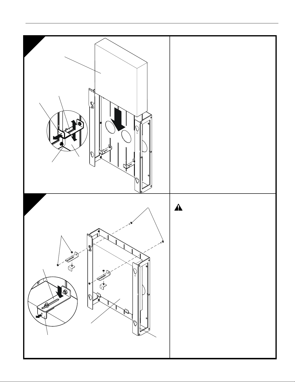
Adjust Lower device Mounting Brackets
1. Position two device holding brackets (20) so that
they are at their outermost position. (see detail in
figure at left)
2. Slide device into rack until resting on two lower
device mounting brackets (30).
3. Slide two device holding brackets (20) forward
until they contact device.
4. Tighten two 1/4-20 Nylock nuts (70)
Install Upper Device Mounting Brackets
WARNING:
IMPROPER INSTALLATION CAN
LEAD TO DEVICE FALLING! All mounting brackets
must be securely fastened to device rack.
IMPORTANT ! : Make certain device holding
brackets (20) are oriented as shown in figure at
left.
1. Install two upper device holding brackets (20) into
slots in upper device mounting brackets (30)
using two 10-24 Nylock nuts (70).
NOTE:
DO NOT tighten hardware at this time.
2. Position two upper device holding brackets (20)
so that they are at their outermost position. (see
detail in figure at left)
3. Secure two upper bottom device mounting
brackets (30) to device rack (10) using two 10-24
x 5/8" round head carriage bolts(60) and two 1024 Nylock nuts (70).
10
60 (2 places)
70 (4 places)
20
30
device
device
20
30
10
70
5
Page 6
Model: PAC-251 Installation Instructions
5
6
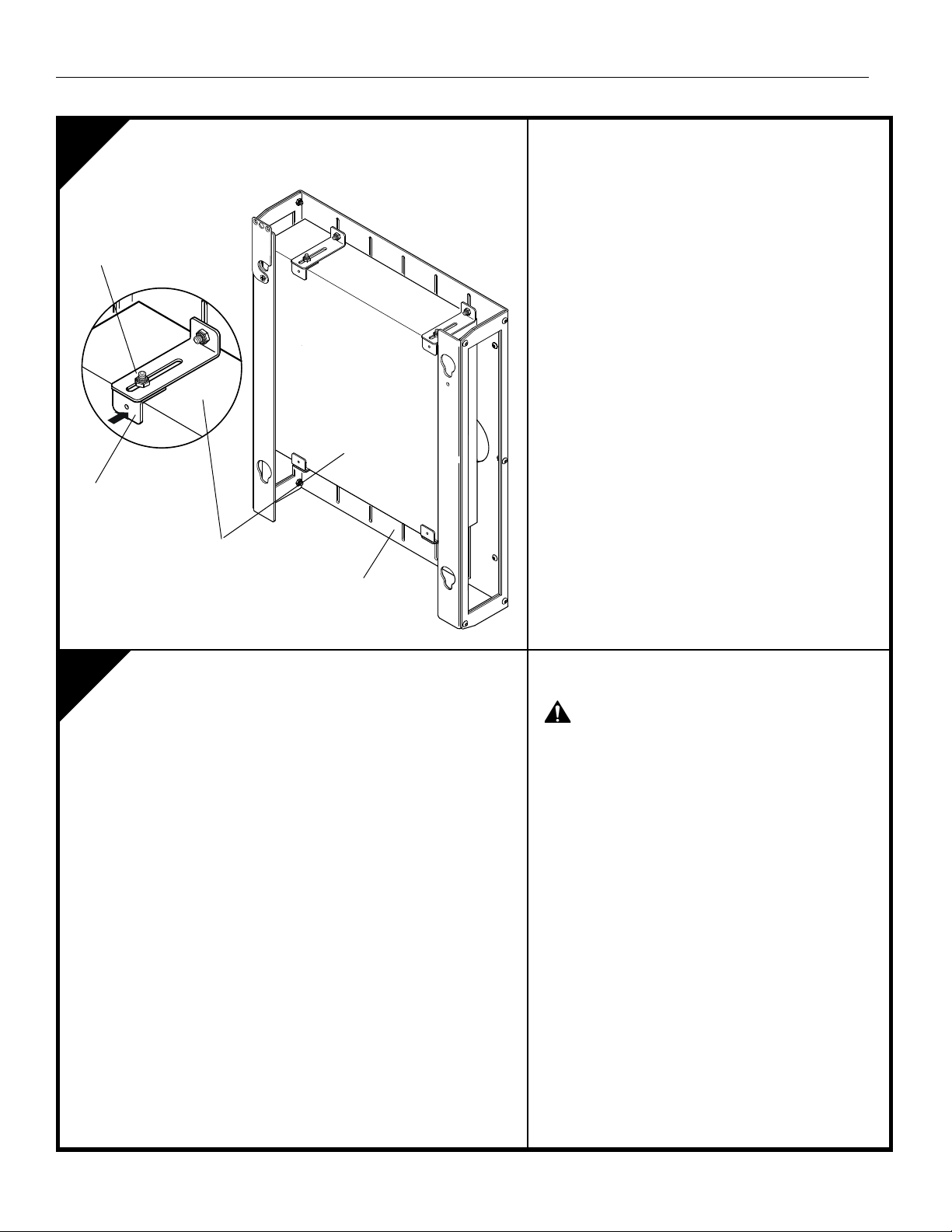
Adjust Upper Device Mounting Brackets
1. Slide two device holding brackes (20) forward until
they contact device. (see detail in figure at left)
2. Tighten two 1/4-20 Nylock nuts (70)
Install Device Accessory with Device to
Mount
WARNING:
COMBINED WEIGHT OF device AND
RACK MAY WEIGHT IN EXCESS OF 40 LBS.
ALWAYS use two people when lifting and follow
proper lifting technicques when installing!
1. Secure device rack with device to PST following
the instructions outlined in the manual provided for
the PST mount.
20
10
device
70
6
 Loading...